EP3644530B1 - Method and device for transmitting or receiving synchronization signal in wireless communication system - Google Patents
Method and device for transmitting or receiving synchronization signal in wireless communication system Download PDFInfo
- Publication number
- EP3644530B1 EP3644530B1 EP18820238.6A EP18820238A EP3644530B1 EP 3644530 B1 EP3644530 B1 EP 3644530B1 EP 18820238 A EP18820238 A EP 18820238A EP 3644530 B1 EP3644530 B1 EP 3644530B1
- Authority
- EP
- European Patent Office
- Prior art keywords
- subframe
- transmitted
- radio frame
- nsss
- npss
- Prior art date
- Legal status (The legal status is an assumption and is not a legal conclusion. Google has not performed a legal analysis and makes no representation as to the accuracy of the status listed.)
- Active
Links
- 238000000034 method Methods 0.000 title claims description 178
- 238000004891 communication Methods 0.000 title claims description 40
- 230000005540 biological transmission Effects 0.000 claims description 84
- 210000004027 cell Anatomy 0.000 description 110
- 238000013507 mapping Methods 0.000 description 42
- 230000002776 aggregation Effects 0.000 description 35
- 238000004220 aggregation Methods 0.000 description 35
- 125000004122 cyclic group Chemical group 0.000 description 33
- 238000012360 testing method Methods 0.000 description 18
- 210000004457 myocytus nodalis Anatomy 0.000 description 17
- 239000000969 carrier Substances 0.000 description 15
- 230000008569 process Effects 0.000 description 13
- 230000000694 effects Effects 0.000 description 12
- 230000015654 memory Effects 0.000 description 12
- 238000001514 detection method Methods 0.000 description 11
- 238000010586 diagram Methods 0.000 description 10
- 238000013468 resource allocation Methods 0.000 description 9
- 230000008859 change Effects 0.000 description 8
- 230000006870 function Effects 0.000 description 8
- 238000012937 correction Methods 0.000 description 5
- 238000013461 design Methods 0.000 description 5
- 238000010295 mobile communication Methods 0.000 description 5
- 238000012546 transfer Methods 0.000 description 5
- 230000008901 benefit Effects 0.000 description 4
- 238000005516 engineering process Methods 0.000 description 4
- 230000004044 response Effects 0.000 description 4
- 230000011664 signaling Effects 0.000 description 4
- 238000001994 activation Methods 0.000 description 3
- 239000011159 matrix material Substances 0.000 description 3
- 238000005259 measurement Methods 0.000 description 3
- 101150071746 Pbsn gene Proteins 0.000 description 2
- 230000004913 activation Effects 0.000 description 2
- 230000003247 decreasing effect Effects 0.000 description 2
- 230000009977 dual effect Effects 0.000 description 2
- 238000012545 processing Methods 0.000 description 2
- 101001056707 Homo sapiens Proepiregulin Proteins 0.000 description 1
- 101100465000 Mus musculus Prag1 gene Proteins 0.000 description 1
- 102100025498 Proepiregulin Human genes 0.000 description 1
- 230000004308 accommodation Effects 0.000 description 1
- 230000004931 aggregating effect Effects 0.000 description 1
- 238000003491 array Methods 0.000 description 1
- 230000001413 cellular effect Effects 0.000 description 1
- 230000008878 coupling Effects 0.000 description 1
- 238000010168 coupling process Methods 0.000 description 1
- 238000005859 coupling reaction Methods 0.000 description 1
- 230000006866 deterioration Effects 0.000 description 1
- 239000002360 explosive Substances 0.000 description 1
- 230000007774 longterm Effects 0.000 description 1
- 238000007726 management method Methods 0.000 description 1
- 238000012986 modification Methods 0.000 description 1
- 230000004048 modification Effects 0.000 description 1
- 238000012544 monitoring process Methods 0.000 description 1
- 230000006855 networking Effects 0.000 description 1
- 238000003825 pressing Methods 0.000 description 1
- 238000004064 recycling Methods 0.000 description 1
- 238000005070 sampling Methods 0.000 description 1
- 238000001228 spectrum Methods 0.000 description 1
Images


Classifications
-
- H—ELECTRICITY
- H04—ELECTRIC COMMUNICATION TECHNIQUE
- H04W—WIRELESS COMMUNICATION NETWORKS
- H04W56/00—Synchronisation arrangements
- H04W56/001—Synchronization between nodes
-
- H—ELECTRICITY
- H04—ELECTRIC COMMUNICATION TECHNIQUE
- H04J—MULTIPLEX COMMUNICATION
- H04J11/00—Orthogonal multiplex systems, e.g. using WALSH codes
- H04J11/0069—Cell search, i.e. determining cell identity [cell-ID]
-
- H—ELECTRICITY
- H04—ELECTRIC COMMUNICATION TECHNIQUE
- H04J—MULTIPLEX COMMUNICATION
- H04J11/00—Orthogonal multiplex systems, e.g. using WALSH codes
- H04J11/0069—Cell search, i.e. determining cell identity [cell-ID]
- H04J11/0076—Acquisition of secondary synchronisation channel, e.g. detection of cell-ID group
-
- H—ELECTRICITY
- H04—ELECTRIC COMMUNICATION TECHNIQUE
- H04W—WIRELESS COMMUNICATION NETWORKS
- H04W4/00—Services specially adapted for wireless communication networks; Facilities therefor
- H04W4/70—Services for machine-to-machine communication [M2M] or machine type communication [MTC]
-
- H—ELECTRICITY
- H04—ELECTRIC COMMUNICATION TECHNIQUE
- H04J—MULTIPLEX COMMUNICATION
- H04J11/00—Orthogonal multiplex systems, e.g. using WALSH codes
- H04J11/0069—Cell search, i.e. determining cell identity [cell-ID]
- H04J11/0073—Acquisition of primary synchronisation channel, e.g. detection of cell-ID within cell-ID group
-
- H—ELECTRICITY
- H04—ELECTRIC COMMUNICATION TECHNIQUE
- H04J—MULTIPLEX COMMUNICATION
- H04J13/00—Code division multiplex systems
- H04J13/0007—Code type
- H04J13/0055—ZCZ [zero correlation zone]
- H04J13/0059—CAZAC [constant-amplitude and zero auto-correlation]
- H04J13/0062—Zadoff-Chu
-
- H—ELECTRICITY
- H04—ELECTRIC COMMUNICATION TECHNIQUE
- H04L—TRANSMISSION OF DIGITAL INFORMATION, e.g. TELEGRAPHIC COMMUNICATION
- H04L5/00—Arrangements affording multiple use of the transmission path
- H04L5/003—Arrangements for allocating sub-channels of the transmission path
- H04L5/0048—Allocation of pilot signals, i.e. of signals known to the receiver
-
- H—ELECTRICITY
- H04—ELECTRIC COMMUNICATION TECHNIQUE
- H04L—TRANSMISSION OF DIGITAL INFORMATION, e.g. TELEGRAPHIC COMMUNICATION
- H04L5/00—Arrangements affording multiple use of the transmission path
- H04L5/14—Two-way operation using the same type of signal, i.e. duplex
-
- H—ELECTRICITY
- H04—ELECTRIC COMMUNICATION TECHNIQUE
- H04J—MULTIPLEX COMMUNICATION
- H04J11/00—Orthogonal multiplex systems, e.g. using WALSH codes
- H04J2011/0096—Network synchronisation
-
- H—ELECTRICITY
- H04—ELECTRIC COMMUNICATION TECHNIQUE
- H04J—MULTIPLEX COMMUNICATION
- H04J2211/00—Orthogonal indexing scheme relating to orthogonal multiplex systems
- H04J2211/003—Orthogonal indexing scheme relating to orthogonal multiplex systems within particular systems or standards
- H04J2211/005—Long term evolution [LTE]
-
- Y—GENERAL TAGGING OF NEW TECHNOLOGICAL DEVELOPMENTS; GENERAL TAGGING OF CROSS-SECTIONAL TECHNOLOGIES SPANNING OVER SEVERAL SECTIONS OF THE IPC; TECHNICAL SUBJECTS COVERED BY FORMER USPC CROSS-REFERENCE ART COLLECTIONS [XRACs] AND DIGESTS
- Y02—TECHNOLOGIES OR APPLICATIONS FOR MITIGATION OR ADAPTATION AGAINST CLIMATE CHANGE
- Y02D—CLIMATE CHANGE MITIGATION TECHNOLOGIES IN INFORMATION AND COMMUNICATION TECHNOLOGIES [ICT], I.E. INFORMATION AND COMMUNICATION TECHNOLOGIES AIMING AT THE REDUCTION OF THEIR OWN ENERGY USE
- Y02D30/00—Reducing energy consumption in communication networks
- Y02D30/70—Reducing energy consumption in communication networks in wireless communication networks
Definitions
- the present disclosure relates to a method for transmitting/receiving a synchronization signal in a wireless communication system, and more particularly, to a method for transmitting/receiving a synchronization signal in a wireless communication system supporting NarrowBand-Internet of Things (NB-loT) and an apparatus supporting the same.
- NB-loT NarrowBand-Internet of Things
- Mobile communication systems have been developed to provide voice services, while guaranteeing user activity.
- Service coverage of mobile communication systems has extended even to data services, as well as voice services, and currently, an explosive increase in traffic has resulted in shortage of resource and user demand for a high speed services, requiring advanced mobile communication systems.
- the requirements of the next-generation mobile communication system may include supporting huge data traffic, a remarkable increase in the transfer rate of each user, the accommodation of a significantly increased number of connection devices, very low end-to-end latency, and high energy efficiency.
- various techniques such as small cell enhancement, dual connectivity, massive Multiple Input Multiple Output (MIMO), in-band full duplex, non-orthogonal multiple access (NOMA), supporting super-wide band, and device networking, have been researched.
- This specification proposes a method for transmitting/receiving a synchronization signal in a wireless communication system supporting NarrowBand-Internet of Things (NB-loT).
- NB-loT NarrowBand-Internet of Things
- this specification proposes a method for differently configuring configurations for NPSS, NSSS, and/or NPBCH in order to distinguish a type of radio frame structure.
- this specification proposes a method for configuring a cover code of NPSS to be applied differently according to the type of radio frame structure.
- this specification proposes a method for generating an NPSS sequence and mapping a resource of the corresponding sequence by considering a frequency offset of the NPSS.
- a wireless device in a wireless communication system is provided as set forth in the appended claims.
- a type of radio frame structure supported or provided by the corresponding cell can be determined.
- the terminal can determine the type of radio frame structure supported or provided by the corresponding cell only by sequence detection other than a blind detection operation for a signal.
- a base station has the meaning of a terminal node of a network over which the base station directly communicates with a device.
- a specific operation that is described to be performed by a base station may be performed by an upper node of the base station according to circumstances. That is, it is evident that in a network including a plurality of network nodes including a base station, various operations performed for communication with a device may be performed by the base station or other network nodes other than the base station.
- the base station (BS) may be substituted with another term, such as a fixed station, a Node B, an eNB (evolved-NodeB), a Base Transceiver System (BTS), or an access point (AP).
- the device may be fixed or may have mobility and may be substituted with another term, such as User Equipment (UE), a Mobile Station (MS), a User Terminal (UT), a Mobile Subscriber Station (MSS), a Subscriber Station (SS), an Advanced Mobile Station (AMS), a Wireless Terminal (WT), a Machine-Type Communication (MTC) device, a Machine-to-Machine (M2M) device, or a Device-to-Device (D2D) device.
- UE User Equipment
- MS Mobile Station
- UT User Terminal
- MSS Mobile Subscriber Station
- SS Subscriber Station
- AMS Advanced Mobile Station
- WT Wireless Terminal
- MTC Machine-Type Communication
- M2M Machine-to-Machine
- D2D Device-to-Device
- downlink means communication from an eNB to UE
- uplink means communication from UE to an eNB.
- a transmitter may be part of an eNB, and a receiver may be part of UE.
- a transmitter may be part of UE, and a receiver may be part of an eNB.
- CDMA Code Division Multiple Access
- FDMA Frequency Division Multiple Access
- TDMA Time Division Multiple Access
- OFDMA Orthogonal Frequency Division Multiple Access
- SC-FDMA Single Carrier Frequency Division Multiple Access
- NOMA Non-Orthogonal Multiple Access
- CDMA may be implemented using a radio technology, such as Universal Terrestrial Radio Access (UTRA) or CDMA2000.
- TDMA may be implemented using a radio technology, such as Global System for Mobile communications (GSM)/General Packet Radio Service (GPRS)/Enhanced Data rates for GSM Evolution (EDGE).
- GSM Global System for Mobile communications
- GPRS General Packet Radio Service
- EDGE Enhanced Data rates for GSM Evolution
- OFDMA may be implemented using a radio technology, such as Institute of Electrical and Electronics Engineers (IEEE) 802.11 (Wi-Fi), IEEE 802.16 (WiMAX), IEEE 802.20, or Evolved UTRA (E-UTRA).
- UTRA is part of a Universal Mobile Telecommunications System (UMTS).
- 3rd Generation Partnership Project (3GPP) Long Term Evolution (LTE) is part of an Evolved UMTS (E-UMTS) using evolved UMTS Terrestrial Radio Access (E-UTRA), and it adopts OFDMA in downlink and adopts SC-FDMA in uplink.
- LTE-Advanced (LTE-A) is the evolution of 3GPP LTE.
- Embodiments of the present disclosure may be supported by the standard documents disclosed in at least one of IEEE 802, 3GPP, and 3GPP2, that is, radio access systems. That is, steps or portions that belong to the embodiments of the present disclosure and that are not described in order to clearly expose the present disclosure may be supported by the documents. Furthermore, all terms disclosed in this document may be described by the standard documents.
- 3GPP LTE/LTE-A or new RAT(RAT in 5G(5 generation) system) is chiefly described, but the technical characteristics of the present disclosure are not limited thereto.
- FIG. 1 shows the structure of a radio frame in a wireless communication system to which an embodiment of the present disclosure may be applied.
- 3GPP LTE/LTE-A support a radio frame structure type 1 which may be applicable to Frequency Division Duplex (FDD) and a radio frame structure which may be applicable to Time Division Duplex (TDD).
- FDD Frequency Division Duplex
- TDD Time Division Duplex
- FIG. 1(a) exemplifies a radio frame structure type 1.
- the type 1 radio frame may be applied to both of full duplex FDD and half duplex FDD.
- a radio frame includes 10 subframes.
- One subframe includes consecutive two slots in the time domain, and subframe i includes slot 2i and slot 2i+1.
- the time required for transmitting a subframe is referred to as a transmission time interval (TTI).
- TTI transmission time interval
- the length of the subframe i may be 1 ms and the length of a slot may be 0.5 ms.
- a UL transmission and a DL transmission I the FDD are distinguished in the frequency domain. Whereas there is no restriction in the full duplex FDD, a UE may not transmit and receive simultaneously in the half duplex FDD operation.
- One slot includes a plurality of Orthogonal Frequency Division Multiplexing (OFDM) symbols in the time domain and includes a plurality of Resource Blocks (RBs) in a frequency domain.
- OFDM symbols are used to represent one symbol period because OFDMA is used in downlink.
- An OFDM symbol may be called one SC-FDMA symbol or symbol period.
- An RB is a resource allocation unit and includes a plurality of contiguous subcarriers in one slot.
- FIG. 1(b) shows frame structure type 2.
- an uplink-downlink configuration is a rule indicating whether uplink and downlink are allocated (or reserved) to all subframes.
- Table 1 shows the uplink-downlink configuration.
- Uplink-Downlink configuration Downlink-to-Uplink Switchpoint periodicity Subframe number 0 1 2 3 4 5 6 7 8 9 0 5ms D S U U U D S U U U 1 5ms D S U U D D S U U D 2 5ms D S U D D D S U D D 3 10ms D S U U U D D D D D 4 10ms D S U U D D D D D D 5 10ms D S U D D D D D D D 6 5ms D S U U U U D S U U D S U U D
- ⁇ S' represents a special subframe including three types of fields including a Downlink Pilot Time Slot (DwPTS), a Guard Period (GP), and a Uplink Pilot Time Slot (UpPTS).
- DwPTS Downlink Pilot Time Slot
- GP Guard Period
- UpPTS Uplink Pilot Time Slot
- a DwPTS is used for an initial cell search, synchronization or channel estimation in a UE.
- a UpPTS is used for channel estimation in an eNB and for synchronizing a UL transmission synchronization of a UE.
- a GP is duration for removing interference occurred in a UL owing to multi-path delay of a DL signal between a UL and a DL.
- the UL-DL configuration may be classified into 7 types, and the position and/or the number of a DL subframe, a special subframe and a UL subframe are different for each configuration.
- a point of time at which a change is performed from downlink to uplink or a point of time at which a change is performed from uplink to downlink is called a switching point.
- the periodicity of the switching point means a cycle in which an uplink subframe and a downlink subframe are changed is identically repeated. Both 5 ms and 10 ms are supported in the periodicity of a switching point. If the periodicity of a switching point has a cycle of a 5 ms downlink-uplink switching point, the special subframe S is present in each half frame. If the periodicity of a switching point has a cycle of a 5 ms downlink-uplink switching point, the special subframe S is present in the first half frame only.
- 0 and 5 subframes and a DwPTS are used for only downlink transmission.
- An UpPTS and a subframe subsequent to a subframe are always used for uplink transmission.
- Such uplink-downlink configurations may be known to both an eNB and UE as system information.
- An eNB may notify UE of a change of the uplink-downlink allocation state of a radio frame by transmitting only the index of uplink-downlink configuration information to the UE whenever the uplink-downlink configuration information is changed.
- configuration information is kind of downlink control information and may be transmitted through a Physical Downlink Control Channel (PDCCH) like other scheduling information.
- Configuration information may be transmitted to all UEs within a cell through a broadcast channel as broadcasting information.
- PDCCH Physical Downlink Control Channel
- Table 2 represents configuration (length of DwPTS/GP/UpPTS) of a special subframe.
- the structure of a radio subframe according to the example of FIG. 1 is just an example, and the number of subcarriers included in a radio frame, the number of slots included in a subframe and the number of OFDM symbols included in a slot may be changed in various manners.
- FIG. 2 is a diagram illustrating a resource grid for one downlink slot in a wireless communication system to which an embodiment of the present disclosure may be applied.
- one downlink slot includes a plurality of OFDM symbols in a time domain. It is described herein that one downlink slot includes 7 OFDMA symbols and one resource block includes 12 subcarriers for exemplary purposes only, and the present disclosure is not limited thereto.
- Each element on the resource grid is referred to as a resource element, and one resource block (RB) includes 12 ⁇ 7 resource elements.
- the number of RBs N ⁇ DL included in a downlink slot depends on a downlink transmission bandwidth.
- the structure of an uplink slot may be the same as that of a downlink slot.
- FIG. 3 shows the structure of a downlink subframe in a wireless communication system to which an embodiment of the present disclosure may be applied.
- a maximum of three OFDM symbols located in a front portion of a first slot of a subframe correspond to a control region in which control channels are allocated, and the remaining OFDM symbols correspond to a data region in which a physical downlink shared channel (PDSCH) is allocated.
- Downlink control channels used in 3GPP LTE include, for example, a physical control format indicator channel (PCFICH), a physical downlink control channel (PDCCH), and a physical hybrid-ARQ indicator channel (PHICH).
- a PCFICH is transmitted in the first OFDM symbol of a subframe and carries information about the number of OFDM symbols (i.e., the size of a control region) which is used to transmit control channels within the subframe.
- a PHICH is a response channel for uplink and carries an acknowledgement (ACK)/not-acknowledgement (NACK) signal for a Hybrid Automatic Repeat Request (HARQ).
- Control information transmitted in a PDCCH is called Downlink Control Information (DCI).
- DCI includes uplink resource allocation information, downlink resource allocation information, or an uplink transmission (Tx) power control command for a specific UE group.
- a PDCCH may carry information about the resource allocation and transport format of a downlink shared channel (DL-SCH) (this is also called an "downlink grant”), resource allocation information about an uplink shared channel (UL-SCH) (this is also called a “uplink grant”), paging information on a PCH, system information on a DL-SCH, the resource allocation of a higher layer control message, such as a random access response transmitted on a PDSCH, a set of transmission power control commands for individual UE within specific UE group, and the activation of a Voice over Internet Protocol (VoIP), etc.
- a plurality of PDCCHs may be transmitted within the control region, and UE may monitor a plurality of PDCCHs.
- a PDCCH is transmitted on a single Control Channel Element (CCE) or an aggregation of some contiguous CCEs.
- CCE is a logical allocation unit that is used to provide a PDCCH with a coding rate according to the state of a radio channel.
- a CCE corresponds to a plurality of resource element groups.
- the format of a PDCCH and the number of available bits of a PDCCH are determined by an association relationship between the number of CCEs and a coding rate provided by CCEs.
- An eNB determines the format of a PDCCH based on DCI to be transmitted to UE and attaches a Cyclic Redundancy Check (CRC) to control information.
- CRC Cyclic Redundancy Check
- a unique identifier (a Radio Network Temporary Identifier (RNTI)) is masked to the CRC depending on the owner or use of a PDCCH. If the PDCCH is a PDCCH for specific UE, an identifier unique to the UE, for example, a Cell-RNTI (C-RNTI) may be masked to the CRC.
- RNTI Radio Network Temporary Identifier
- a paging indication identifier for example, a Paging-RNTI (P-RNTI) may be masked to the CRC.
- P-RNTI Paging-RNTI
- SIB System Information Block
- SI-RNTI System Information-RNTI
- RA-RNTI Random Access-RNTI
- the enhanced PDCCH (EPDCCH) carries UE-specific signaling.
- the EPDCCH is located in a physical resource block (PRB) that is configured to be UE specific.
- PRB physical resource block
- the PDCCH may be transmitted in up to three OFDM symbols in the first slot in the subframe, but the EPDCCH can be transmitted in a resource region other than the PDCCH.
- the time (i.e., symbol) at which the EPDCCH starts in the subframe may be configured in the UE via higher layer signaling (e.g., RRC signaling, etc.).
- the EPDCCH may carry a transport format, resource allocation, and HARQ information associated with DL-SCH, a transport format, resource allocation, and HARQ information associated with UL-SCH, resource allocation information associated with Sidelink Shared Channel (SL-SCH) and Physical Sidelink Control Channel (PSCCH), etc.
- Multiple EPDCCHs may be supported and the UE may monitor the set of EPCCHs.
- the EPDCCH may be transmitted using one or more successive enhanced CCEs (ECCEs) and the number of ECCEs per EPDCCH may be determined for each EPDCCH format.
- ECCEs enhanced CCEs
- Each ECCE may be constituted by a plurality of enhanced resource element groups (EREGs).
- the EREG is used for defining mapping of the ECCE to the RE.
- the UE may monitor a plurality of EPDCCHs.
- one or two EPDCCH sets may be configured in one PRB pair in which the UE monitors EPDCCH transmission.
- Different coding rates may be implemented for the EPCCH by merging different numbers of ECCEs.
- the EPCCH may use localized transmission or distributed transmission, and as a result, the mapping of the ECCE to the RE in the PRB may vary.
- FIG. 4 shows the structure of an uplink subframe in a wireless communication system to which an embodiment of the present disclosure may be applied.
- the uplink subframe may be divided into a control region and a data region in a frequency domain.
- a physical uplink control channel (PUCCH) carrying uplink control information is allocated to the control region.
- a physical uplink shared channel (PUSCH) carrying user data is allocated to the data region.
- PUCCH physical uplink control channel
- PUSCH physical uplink shared channel
- a Resource Block (RB) pair is allocated to a PUCCH for one UE within a subframe. RBs belonging to an RB pair occupy different subcarriers in each of 2 slots. This is called that an RB pair allocated to a PUCCH is frequencyhopped in a slot boundary.
- a communication environment considered in embodiments of the present disclosure includes all multi-carrier support environments. That is, a multi-carrier system or carrier aggregation (CA) system used in the present disclosure is a system in which, when a target wide band is configured, one or more component carriers (CCs) having a bandwidth smaller than a target bandwidth are aggregated and used in order to support a wide band.
- CA carrier aggregation
- multi-carriers refer to aggregation (or carrier aggregation) of carriers and in this case, the aggregation of the carriers refers to both aggregation of contiguous carriers and aggregation of noncontiguous carriers.
- the number of components carriers aggregated between the downlink and the uplink may be set differently.
- a case where the number of downlink component carriers (hereinafter, referred to as ⁇ DL CC') is equal to the number of uplink component carriers (hereinafter, referred to as ⁇ UL CC') is referred to as symmetric aggregation and a case where the number of downlink CCs is different from the number of uplink CCs is referred to as asymmetric aggregation.
- Such carrier aggregation may be used interchangeably with terms such as carrier aggregation, bandwidth aggregation, spectrum aggregation, and the like.
- Carrier aggregation configured by combining two or more component carriers aims at supporting up to 100 MHz bandwidth in the LTE-A system.
- the bandwidth of the combined carriers may be limited to the bandwidth used in the existing system in order to maintain backward compatibility with the existing IMT system.
- a bandwidth larger than 20 MHz may be supported by using only the bandwidths for compatibility with the existing system.
- the carrier aggregation system used in the present disclosure may support the carrier aggregation by defining a new bandwidth regardless of the bandwidth used in the existing system.
- the LTE-A system uses a concept of a cell to manage radio resources.
- the aforementioned carrier aggregation environment may be referred to as a multiple-cell environment.
- the cell is defined as a combination of a pair of a downlink resource (DL CC) and an uplink resource (UL CC), but the uplink resource is not required. Accordingly, the cell may be constituted by the downlink resource along or by the downlink resource and the uplink resource.
- the specific user equipment may have one DL CC and one UL CC, but when the specific user equipment has two or more configured serving cells, the specific user equipment may have DL CCs as many as the cells and the number of UL CCs may be equal to or smaller therethan.
- the DL CC and the UL CC may be configured. That is, when the specific user equipment has multiple configured serving cells, a carrier aggregation environment in which the number of UL CCs is larger than the number of DL CCs may also be supported. That is, the carrier aggregation may be appreciated as aggregation of two or more different cells having carrier frequencies (center frequency of the cell), respectively.
- the term 'cell' needs to be distinguished from a 'cell' as an area covered by the eNB which is generally used.
- the cell used in the LTE-A system includes a primary cell (PCell) and a secondary cell (SCell).
- the P cell and the S cell may be used as the serving cell.
- a user equipment which is in an RRC_CONNECTED state but does not configure the carrier aggregation or does not support the carrier aggregation
- only one serving cell configured only by the P cell exists.
- one or more serving cells may exist and the entire serving cell includes the P cell and one or more S cells.
- the serving cell (P cell and S cell) may be configured through an RRC parameter.
- PhysCellld has integer values of 0 to 503 as a physical layer identifier of the cell.
- SCelllndex has integer values of 1 to 7 as a short identifier used for identifying the S cell.
- ServCelllndex has integer values of 0 to 7 as a short identifier used for identifying the serving cell (P cell or S cell).
- the 0 value is applied to the P cell and SCelllndex is previously granted to be applied to the S cell. That is, a cell having the smallest cell ID (or cell index) in ServCelllndex becomes the P cell.
- the P cell refers to a cell operating on a primary frequency (or primary CC).
- the user equipment may be used to perform an initial connection establishment process or a connection re-establishment process and may refer to a cell indicated during a handover process. Further, the P cell refers to a cell which becomes a center of control related communication among the serving cells configured in the carrier aggregation environment. That is, the user equipment may be allocated the PUCCH only in the P cell thereof and may transmit the allocated PUCCH and may use only the P cell for acquiring system information or changing a monitoring procedure. Evolved Universal Terrestrial Radio Access (E-UTRAN) may change only the P cell for the handover procedure by using an RRC connection reconfiguration message of a higher layer, which includes mobility control information to the user equipment that supports the carrier aggregation environment.
- E-UTRAN Evolved Universal Terrestrial Radio Access
- the S cell refers to a cell operating on a second frequency (or secondary CC). Only one P cell may be allocated to the specific user equipment and one or more S cells may be allocated to the specific user equipment.
- the S cell may be configured after the RRC connection is configured and may be used to provide an additional radio resource.
- the PUCCH does not exist in remaining cells other than the P cell among the serving cells configured in the carrier aggregation environment, that is, the S cell.
- the E-UTRAN adds the S cell to the user equipment supporting the carrier aggregation environment, the E-UTRAN may provide all the system information related to the operation of a related cell which is in the RRC_CONNECTED state through a dedicated signal.
- the change of the system information may be controlled by releasing and adding the related S cell and the RR connection reconfiguration message of the higher layer may be used at this time.
- the E-UTRAN may perform dedicated signaling with different parameters for each user equipment rather than broadcasting within the related S cell.
- the E-UTRAN may configure a network including one or more S cells in addition to the P cell initially configured in the connection configuration process.
- the P cell and the S cell may operate as respective component carriers.
- the primary component carrier (PCC) may be used in the same meaning as the P cell and the secondary component carrier (SCC) may be used in the same meaning as the S cell.
- FIG. 5 illustrates examples of a component carrier and carrier aggregation in a wireless communication system to which the present disclosure may be applied.
- FIG. 5(a) illustrates a single carrier structure used in the LTE system.
- the component carrier includes the DL CC and the UL CC.
- One component carrier may have a frequency range of 20 MHz.
- FIG. 5(b) illustrates a carrier aggregation structure used in the LTE-A system.
- FIG. 5(b) illustrates a case where three component carriers having a frequency magnitude of 20 MHz are combined. There are three DL CCs and three UL CCs, but the numbers of DL CCs and UL CCs are not limited.
- the UE may simultaneously monitor three CCs, and receive a downlink signal/data and transmit an uplink signal/data.
- the network may allocate M (M ⁇ N) DL CCs to the user equipment.
- the UE may monitor only M limited DL CCs and receive the DL signal.
- the network may allocate a primary DL CC to the user equipment by assigning priorities to L (L ⁇ M ⁇ N) DL CCs and in this case, the UE needs to particularly monitor L DL CCs.
- Such a scheme may be similarly applied even to uplink transmission.
- a linkage between the carrier frequency (or DL CC) of the downlink resource and the carrier frequency (or UL CC) of the uplink resource may be indicated by a higher layer message such as an RRC message or system information.
- a combination of the DL resource and the UL resource may be configured by a linkage defined by System Information Block Type2 (SIB2).
- SIB2 System Information Block Type2
- the linkage may refer to a mapping relationship between a DL CC in which a PDCCH carrying a UL grant is transmitted and a UL CC that uses the UL grant or may refer to a mapping relationship between a DL CC (or UL CC) in which data for HARQ is transmitted and a UL CC (or DL CC) in which an HARQ ACK/NACK signal is transmitted.
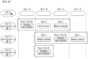
- FIG. 6 is a diagram illustrating division of cells of a system supporting carrier aggregation.
- a configured cell may be configured for each UE as a cell capable of aggregating carriers based on a measurement report among cells of the eNB as illustrated in FIG. 5 .
- the configured cell may reserve resources for ack/nack transmission in advance for PDSCH transmission.
- the activated cell is a cell configured to actually transmit PDSCH/PUSCH among the configured cells and performs channel state information (CSI) reporting and sounding reference signal (SRS) transmission for PDSCH/PUSCH transmission.
- the de-activated cell is a cell that prevents the PDSCH/PUSCH transmission by a command or timer operation of the eNB, and may also stop the CSI reporting and the SRS transmission.
- the synchronization signal may be classified into a Narrowband Primary Synchronization Signal (NPSS) and a Narrowband Secondary Synchronization Signal (NSSS).
- NPSS Narrowband Primary Synchronization Signal
- NSSS Narrowband Secondary Synchronization Signal
- 504 unique physical layer identifiers may be indicated by the NSSS.
- a sequence d l (n) used for the NPSS may be generated from a Zadoff-Chu sequence on a frequency domain according to Equation 1.
- d l n S l ⁇ e ⁇ j ⁇ un n + 1 11
- n 0,1 , ... , 10
- a Zadoff-Chu root sequence index u may be 5 and an S(I) value for a different symbol index I may be given by Table 3.
- Table 3 shows a definition of the S(I) value. [Table 3] Cyclic prefix length S (3),..., S (13) Normal 1 1 1 1 -1 -1 1 1 1 -1 1
- the sequence used for the NPSS may be mapped to a resource element(s) through the following scheme.
- the same antenna port may be used with respect to all symbols of the NPSS in the subframe.
- the UE may not assume that the NPSS is transmitted through the same antenna port as a random downlink reference signal. Further, the UE may not assume that NPSS transmission in a given subframe uses the same antenna port(s) as the NPSS in another random subframe.
- a sequence d l (n) may be mapped to a resource element (k, I) in subframe #5 of every radio frame (i.e., frame) and the sequence d l (n) may be mapped in an order in which an index k increases and then mapped in an order in which an index I increases.
- the corresponding sequence element d(n) may not be used for the NPSS, but may be counted in a mapping procedure.
- a sequence d l (n) used for the NSSS may be generated from the Zadoff-Chu sequence on the frequency domain according to Equation 2.
- Equation 2 a binary sequence b q (m) is given by Table 4 and a cyclic shift ⁇ f in frame number n f is given by Equation 3. [Table 4] q b q (0)...., b q (127) 0 [1 1 1 1 1 1 1 1 1 1 1 1 1 1 1 1 1 1 1 1 1 1 1 1 1 1 1 1 1 1 1 1 1 1 1 1 1 1 1 1 1 1 1 1 1 1 1 1 1 1 1 1 1 1 1 1 1 1 1 1 1 1 1 1 1 1 1 1 1 1 1 1 1 1 1 1 1 1 1 1 1 1 1 1 1 1 1 1 1 1 1 1 1 1 1 1 1 1 1 1 1 1 1 1 1 1 1 1 1 1 1 1 1 1 1 1] 1 [1 -1 -1 1-1 1 1 -1 1 1 -1 1 -1 1 -1 1 -1 1 1 -1 1 -1 1 1 -1 1 1 1 -1 1 -1 1 -1 1 -1 1 -1 1 -1 1 -1 1 -1 1 -1 1 -1 -1
- the sequence used for the NSSS may be mapped to the resource element(s) through the following scheme.
- the same antenna port needs to be used with respect to all symbols of the NSSS in the subframe.
- the UE may not assume that the NSSS is transmitted through the same antenna port as a random downlink reference signal. Further, the UE may not assume that NSSS transmission in a given subframe uses the same antenna port(s) as the NSSS in another random subframe.
- the sequence d(n) is sequentially mapped to the resource element (k, I) from d(0).
- the sequence d(n) may be mapped in an order in which a first index k increases over 12 allocated subcarriers in subframe #9 of the radio frame and mapped in the order in which the index I increases over a last N symb NSSS symbol allocated thereafter.
- a N symb NSSS value may be given by Table 5. [Table 5] Cyclic prefix length N symb NSSS Normal 11
- the corresponding sequence element d(n) may not be used for the NSSS, but may be counted in a mapping procedure.
- 'aNPSS' may mean an advanced NPSS and 'sNSSS' may mean advanced NSSS.
- 'aNPSS' may correspond to a part of the type of NPSS or may be defined separately from the NPSS.
- 'aNSSS' may correspond to a part of the type of NSSS or may be defined separately from the NSSS.
- the additionally considered aNPSS is configured by the same signal as the existing NPSS defined by Equation 1 described above, it may be difficult for the NB-loT UE to distinguish whether the detected sequence is received from the base station that transmits both the NPSS and the aNPSS or whether the NPSS is received from base stations having different transmission time.
- the aNPSS needs to be configured differently from the existing NPSS and this needs to be designed by a method that minimizes the increase in implementation and computation complexity of the NB-loT UE without being higher than the PAPR of the NPSS.
- a root index and a cover code of the Zadoff-Chu sequence may be changed.
- the aNPSS may be configured so as to use 6 as the u value of Equation 1 described above.
- a correlation may be acquired through one complex multiplication every sample. Further, this may have the same PAPR characteristic as the NPSS and a correlation value with the NPSS has a low value in the sequence having the length of L.
- the legacy (i.e., existing) NB-IoT UE will not detect the aNPSS and the NB-loT UE using the aNPSS may reutilize a correlation module for the NPSS.
- This is advantageous in terms of complexity when it may not be known whether the base station of an anchor carrier transmits the aNPSS at the time of initial cell search.
- the Zadoff-Chu sequence has the same structure as the existing sequence, it may be advantageous in that the same weight may be applied in accumulating the correlation values for the NPSS and the aNPSS, respectively.
- the NB-loT UE may perform auto-correlation characteristic based cell search for detecting the NPSS by using the characteristics of the cover code S(I) defined in Equation 1 described above.
- FIG. 7 illustrates an auto-correction characteristic of NPSS or aNPSS when a cover code is applied.
- FIGS. 7b to 7d illustrate the auto-correlation characteristic of the aNPSS in the case of applying a cover code different from the cover code of the existing NSSS to the aNPSS.
- a graph corresponding to the legacy NB-loT shows a case where the NB-loT UE estimates the auto-correlation by using the cover code of the existing NPSS and an NB-loT graph considered in the NR system (e.g., Rel. 15) shows a case where the auto-correlation is estimated by applying a newly added cover code in each figure.
- an auto-correlation value has a maximum value in specific ⁇ which is an accurate timing and has a peak (i.e., narrow peak) in a narrow region based on the corresponding timing. Further, a side peak value other than the peak including the maximum value has a relatively low value.
- the cover code used in FIG. 7b does not almost have the side peak value, but has the peak (i.e., wide peak) in a wide region around the accurate timing. This may cause timing estimation performance of the UE to deteriorate.
- cover code used in FIG. 7c has the narrow peak at an accurate timing location, but has a relatively high side peak value over an immediately adjacent region.
- the cover code used in FIG. 7d has the narrow peak similar to that in FIG. 7a at the accurate timing location and has a lower side peak than that in FIG. 7c .
- the aNPSS has an auto-correlation characteristic which may not almost influence detection of the NPSS of the legacy NB-loT UE. Accordingly, [1 1 -1 1 -1 -1 1 -1 1 -1 1] may be considered as the cover code S(I) of the aNPSS.
- the detection of the NSSS of the legacy UE may be influenced.
- the aNSSS may be configured by using a method for adding b q (m) of the NSSS defined in Table 4 described above and a modified resource mapping method. Additionally, the aNSSS may be configured through a method for adding a value of ⁇ f .
- the legacy NB-loT UE does not attempt to detect the changed or added b q (m) and the NB-loT UE that attempts to detect the aNSSS has an advantage of recycling a result of a complex multiplication used for detecting the NSSS. Accordingly, in b q (m) used for the aNSSS, columns 16, 48, 80, and 112 which are values other than columns 1, 32, 64, and 128 of a 128-order Hadamard matrix used in b q (m) of the existing NSSS.
- ⁇ f may be circulated in 0, 33/132, 66/132, and 99/132 at every 20 msec.
- ⁇ f may be circulated in 33/264, 99/264, 165/264, and 231/264 at every 20 msec, circulated in some sets of four values, or fixed to a specific value.
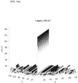
- FIG. 8 illustrates cross-correlation values of NSSS or aNSSS according to a cyclic shift value ⁇ f .
- FIG. 8 illustrates a cross-correlation value (e.g., Rel.15 NB-IoT w/aNSSS) using the ⁇ f value applied to aNSSS and a cross-correlation value (e.g., Rel.15 NB-IoT w/NSSS) using ⁇ f of the NSSS when receiving the aNSSS in which a cross-correlation value (e.g., Legacy NB-loT w/NSSS) ⁇ f is selected among 33/264, 99/264, 165/264, and 231/264 in the case of using the NSSS.
- a cross-correlation value e.g., Legacy NB-loT w/NSSS
- a sequence cross-correlation characteristic of the NSSS may deteriorate.
- a method for randomizing the cross-correlation characteristic between the NSSS and the aNSSS during a resource mapping process may be considered.
- FIG. 9 illustrates examples of a resource mapping method for NSSS or aNSSS.
- FIGS. 9a to 9d illustrate a resource mapping scheme in which the NSSS or the aNSSS is allocated by a frequency first mapping scheme from a k s -th resource element (RE) location of an I s -th OFDM symbol and the NSSS and the aNSSS are sequentially mapped according to solid-line and dotted-line arrows up to a k e -th RE location of an I e -th OFDM symbol.
- RE resource element
- FIG. 9a illustrates a resource mapping scheme for the NSSS
- FIG. 9b illustrates a scheme of moving a resource mapping start OFDM symbol location by a specific value in FIG. 9
- FIG. 9c illustrates a scheme of performing a resource mapping order of the scheme of FIG. 9a reversely
- FIG. 9d illustrates a scheme which has the same start and end locations as the scheme of FIG. 9a , but applies a time first mapping scheme.
- FIG. 10 illustrates an NSSS cross-correlation characteristic of a legacy NB-IoT UE according to a resource mapping scheme.
- FIGS. 10a to 10d illustrate the Zadoff-Chu sequence of the NSSS of the legacy NB-loT UE according to each resource mapping scheme described in FIGS. 9a to 9d .
- the NSSS Zadoff-Chu sequence cross-correlation characteristics of the legacy NB-loT UE, u and u' are the same as each other, the NSSS Zadoff-Chu sequence cross-correlation characteristics have a value as large as a sequence length and if not, the NSSS Zadoff-Chu sequence has a relatively low cross-correlation characteristic.
- the scheme of FIG. 10b has a value corresponding to approximately 50% in the existing NSSS Zadoff-Chu sequence and a combination of some u and u'. Further, the scheme of FIG.
- FIG. 10c shows a low cross-correlation value with the existing NSSS Zadoff-Chu sequence in most combinations of u and u', but has a cross-correlation value of approximately 70% or more in a specific u and u' combination. On the contrary, it can be confirmed that the scheme of FIG. 10d has a relatively low cross-correlation value with the existing Zadoff-Chu sequence in all u and u' combinations.
- the time first mapping scheme illustrated in FIG. 10d is considered and start and end RE locations of resource mapping may be circularly shifted by a specific value.
- the method for adding the ⁇ f is not particularly applied similarly with the proposed b q (m) and may be applied in the case of following the resource mapping scheme of a different method other than the proposed resource mapping scheme.
- column values of the 128-order Hadarmard matrix of the proposed b q (m) may be simultaneously applied in combination with the resource mapping scheme in FIG. 10d which is proposed.
- b q (m) of the existing NSSS and the resource mapping scheme illustrated in FIG. 10d may be combined and applied or the resource mapping scheme of the existing NSSS and the column values of the 128-order Hadarmard matrix of the proposed b q (m) are combined and configured.
- structures and transmission locations of the NPSS and the NSSS may be applied when only the NPSS is additionally transmitted or independently applied even when only the NSSS is additionally transmitted. That is, even when the NPSS and the NSSS having a new sequence other than the NPSS and the NSSS are additionally transmitted, subframe and radio frame locations in which the sequence is additionally transmitted may follow the aforementioned scheme.
- the NB-loT UE may determine that system information (e.g., MIB-NB or SIB1-NB) may also be additionally transmitted. That is, the NB-loT UE may attempt additional detection of the MIB-NB and SIB1-NB which are additionally transmitted together with the existing detection attempt of the MIB-NB and SIB1-NB according to whether the aNPSS and the aNSSS are detected. In an opposite case, when the NB-loT UE determines that the cell is a cell in which the system information is additionally provided, the NB-loT UE may also determine whether to transmit the aNPSS and the aNSSS of the cell.
- system information e.g., MIB-NB or SIB1-NB
- the base station should not continuously periodically transmit the aNPSS and the aNSSS together with the NPSS and the NSSS and the aNPSS and the aNSSS may be transmitted for a specific time according to a need of the base station. Further, whether the aNPSS and the aNSSS are periodically or aperiodically transmitted may be mutually independently determined and information (e.g., transmission period and interval) related to transmission of the aNPSS and the aNSSS may be configured by the base station for a specific operation such as measurement of the NB-loT UE.
- information e.g., transmission period and interval
- the base station may start or stop transmission of the aNPSS and the aNSSS with respect to a case of satisfying a specific condition.
- start and stop of transmission of the aNPSS and the aNSSS may be notified to some or all UEs in the cell.
- the aforementioned contents may be similarly applied even to a system such as enhanced Machine Type Communication (eMTC) utilizing a part of an LTE system bandwidth in addition to an NB-loT system.
- eMTC enhanced Machine Type Communication
- a new synchronization signal or the existing PSS and/or SSS is modified and transmitted in order to efficiently improve a delay for cell search and acquisition of the system information in the eMTC
- this may indicate that the information (e.g., MIB and/or SIB1-BR) related to the system information is also additionally transmitted in the corresponding cell.
- the information e.g., MIB and/or SIB1-BR
- the UE may expect that there will be an enhanced synchronization in the corresponding cell when enhanced system information is additionally transmitted in a subsequent process.
- the case may be divided into two cases as described below according to support an NB-loT service in the corresponding cell.
- the eMTC UE may expect the enhancement of the cell search performance by additionally receiving the NPSS and/or NSSS transmitted for the NB-loT service in the corresponding cell.
- a signal for cell search of LTE and a signal for cell search of NB-loT may be simultaneously transmitted. Accordingly, the eMTC UE may directly select which signal may be selectively received by the eMTC UE or may perform an operation instructed from the base station.
- the base station may additionally transmit the NPSS and the NSSS for enhancement of the cell search performance of the eMTC UE.
- the base station needs to transmit signals different from the existing NPSS and NSSS in order to prevent misrecognizing that another NB-loT UE serves the NB-loT in the corresponding cell by receiving the NPSS and the NSSS.
- the aforementioned aNPSS and aNSSS may be used.
- the aNPSS and the aNSSS may be transmitted at a location different from the subframe location and may be transmitted at a non-anchor carrier location other than the anchor carrier location.
- the aNPSS and the aNSSS may be transmitted by configuring an NB-loT cell identifier different from an LTE cell identifier and even in such a case, a mapping scheme for the LTE cell identifier and the NB-loT cell identifier may be defined.
- the aNPSS and the aNSSS are transmitted not for serving the actual NB-loT UE, there is a difference in that the aNPSS and the aNSSS may be transmitted without a Narrowband Reference Signal.
- the proposed aNPSS and aNSSS may be utilized as an instruction signal such as update of the system information in addition to a purpose such as the cell search performance enhancement of a narrow band system such as the NB-loT and the eMTC.
- the update of the system information may mean information (e.g., MIB and SIB) on the cell, which the UE should basically or additionally receive from the cell.
- the base station may generally instruct the UE to update the system information through a paging indication or a paging message.
- the legacy system e.g., LTE system
- whether to update (or change) the system information is indicated through PDCCH, MPDCCH, or NPDCCH scrambled with P-RNTI in a specific interval (paging occasion).
- PDCCH Physical Downlink Control Channel
- MPDCCH Physical Downlink Control Channel
- NPDCCH Physical Downlink Control Channel
- NPDCCH Physical Downlink Control Channel
- the aNPSS and the aNSSS should not be continuously transmitted to some subframe locations and may be restricted to a specific location in association with the paging occasion and periodically or aperiodically transmitted.
- an operation of the UE which detects the utilization as the paging indicator may be defined not to perform an operation related to the update of the system information or the update of the system information during a specific interval.
- the aNPSS and the aNSSS transmitted from the same base station may be the same signal and/or sequence each time. That is, when the aNPSS and the aNSSS are utilized for the purpose of the cell search, the aNPSS and the aNSSS need to transfer the same information (e.g., cell identifier and radio frame number) every transmission, but when the aNPSS and the aNSSS are utilized for the purpose such as the paging indicator, another information may be transferred every aNPSS and/or aNSSS transmission.
- the same information e.g., cell identifier and radio frame number
- the aforementioned aNPSS and aNSSS may be used for distinguishing duplex modes of TDD and FDD.
- the aNPSS and the aNSSS may be transmitted at locations different from the aforementioned subframe location.
- the route u and/or the cover code of the aNPSS may be used in order to distinguish a UL-DL configuration.
- the cover code may be used in order to distinguish the dual modes and the root u may be used in order to distinguish the UL-DL configuration.
- the type of root u and/or cover code may be used so as to distinguish only some of the UL-DL configurations. That is, when relative locations of the (a)NPSS and the (a)NSSS may vary depending on the UL-DL configuration, it is sufficient if the (a)NPSS may transfer information to only distinguish the relative location relationship with the (a)NSSS.
- the UE may acquire an actual UL-DL configuration through MIB-NB or SIB for TDD after detecting the (a)NPSS and the (a)NSSS.
- Narrowband (NB)-LTE refers to a system for supporting low complexity and low power consumption with a system bandwidth (system BW) corresponding to 1 Physical Resource Block (PRB) of LTE system.
- system BW system bandwidth
- PRB Physical Resource Block
- the NB-LTE system may be primarily used as a communication mode for supporting a device (or UE) such as a machine-type communication (MTC) UE and/or an loT UE in a cellular system. That is, the NB-LTE system may be referred to as the NB-loT system.
- a device or UE
- MTC machine-type communication
- loT loT UE
- the NB-loT system does not need to allocate an additional band for the NB-loT system by using the same OFDM parameters such as the subcarrier spacing used in the existing LTE system, as the LTE system.
- 1 PRB of the legacy LTE system band is allocated for the NB-loT, which is advantageous in using the frequency efficiently.
- the physical channel of the NB-loT system may be defined as N-Primary Synchronization Signal (N-PSS), N-Secondary Synchronization Signal (N-SSS), N-Physical Channel (N-PBCH), N-PDCCH/N-EPDCCH, N-PDSCH, or the like in the case of downlink.
- N-PSS N-Primary Synchronization Signal
- N-SSS N-Secondary Synchronization Signal
- N-PBCH N-Physical Channel
- N-PDCCH/N-EPDCCH N-PDSCH
- ⁇ N- ⁇ may be used for distinguishing from the legacy LTE.
- a method for generating a sequence and mapping a resource described in this specification is described based on a transmission unit (e.g., subframe) in the LTE system, but may be applied even to a transmission unit (e.g., a short transmission unit, the subframe, a slot, etc.) in the NR system in the same scheme or similarly.
- a transmission unit e.g., subframe
- a transmission unit e.g., a short transmission unit, the subframe, a slot, etc.
- the PRB referred to herein may be interpreted as the same meaning as the carrier.
- DCI format N0, DCI format N1, and DCI format N2 referred to herein may refer to DCI format N0, DCI format N1, and DCI format N2 described above (e.g., defined in the 3GPP specification).
- an anchor-type PRB may mean a PRB for transmitting the N-PDSCH for N-PSS, N-SSS, N-PBCH, and/or system information block (N-SIB) for the initial access in terms of the base station.
- N-SIB system information block
- the specific anchor-type PRB selected by the UE through the initial access is an anchor PRB or anchor carrier.
- a PRB allocated from the base station to perform a downlink process (or procedure) after the initial access may be referred to as an additional PRB (or additional carrier).
- the UE may be configured to distinguish the radio frame structure due to a difference between the transmission locations of the PSS and the SSS in order for the UE to know the type of radio frame structure provided by the corresponding cell in an initial access step.
- the radio frame structure may be divided into a first type to support Frequency Division Duplex (FDD) and a second type to support Time Division Duplex (TDD).
- FDD Frequency Division Duplex
- TDD Time Division Duplex
- FIG. 11 illustrates a transmission location of a synchronization signal according to a radio frame structure of an LTE system.
- the PSS may be transmitted in symbol #6 of subframe #0 and the SSS may be transmitted in a symbol immediately before the PSS, i.e., symbol #5 of subframe #0.
- the PSS may be transmitted in symbol #2 of subframe #1 and the SSS may be transmitted in symbol #13 of subframe #0 which is earlier than the PSS by 3 symbols.
- '#n' may mean 'n-th'. That is, subframe #0 may mean a 0-th subframe of the radio frame.
- the UE may distinguish whether the corresponding cell provides the TDD or the FDD as the difference in location where the PSS and the SSS are transmitted.
- the UE may select one of four candidates (i.e., TDD in the case of the normal CP, FDD in the case of the normal CP, TDD in the case of the extended CP, and FDD in the case of the extended CP) including the normal cyclic prefix (CP) and the extended CP.
- a TDD operation i.e., an operation using a second type of radio frame structure
- the base station is considered in the NB-loT of the NR system (or enhanced LTE system)
- a method for configuring the radio frame structure to be distinguished in the initial access step due to the aforementioned reason may be considered.
- this specification proposes a method for configuring the type of radio frame structure to be distinguished in the initial access step by using the NPSS (or the aforementioned aNPSS) and the NSSS (or the aforementioned aNSSS).
- the embodiments proposed by this specification may be used for distinguish other information in addition to distinguishing the type of radio frame structure.
- a method(s) described below may be used for distinguishing information such as an operation mode, a CP length, Synchronization Signal Periodicity, etc.
- an in-band mode and/or guard mode may be indicated according to the existing scheme and a standalone mode may be indicated by a new scheme.
- an additionally considered radio frame structure may be a third type of radio frame structure (frame structure type 3) of the LTE system or a newly introduced radio frame structure.
- a method for configuring the TDD or FDD to be distinguished by changing a density of the NSSS or NPSS may be considered.
- the density of the NSSS or NPSS may be configured by a period in which the NSSS or NPSS is transmitted, i.e., a transmission period.
- the corresponding method is a method for distinguishing the radio frame structure by differently configuring the transmission period (i.e., sequence density) of the NSSS or NPSS in the second type of radio frame structure corresponding to the TDD from the transmission period of the NSSS or NPSS in the first type of radio frame structure corresponding to the FDD.
- the corresponding method is described only for the case of the NSSS for convenience of description, but this may be extensively applied even to the case of the NPSS, of course.
- the NSSS is configured to be transmitted by occupying one subframe per 20 ms. Specifically, the NSSS is transmitted through 11 symbols among 14 symbols of subframe #9 every 20 ms. Here, three remaining symbols may correspond to a region configured for transmitting a downlink control channel.
- Equation 2 a sequence used for the NSSS is shown in Equation 2 described above and a binary sequence b q (m) is shown in Table 4 described above. Further, a cyclic shift ⁇ f in frame number n f is shown in Equation 3.
- the cyclic shift value ⁇ f may be one value of ⁇ 0, 1/4, 1/2, 3/4 ⁇ according to the frame number.
- four different sequences are used for the NPSSS in order to determine (or check) a boundary of 80 ms by using the NSSS transmitted every 20 ms. In this case, four different sequences may be used every 20 ms within 80 ms.
- the density of the NSSS used for the TDD is configured to a half by comparing with the existing density in order to distinguish the radio frame structure, only two among four cyclic shift values may be configured to be used in order to distinguish the boundary of 80 ms through the NSSS. That is, when the NSSS occupies one subframe (e.g., subframe #9) every 40 ms (e.g., occupies only 11 symbols among 14 symbols), only two among the cyclic shift values ⁇ f ⁇ 0, 1/4, 1/2, 3/4 ⁇ may be used.
- the cyclic shift value ⁇ f of the NSSS used for the TDD may be configured to one of ⁇ 0, 1/2 ⁇ according to the frame number.
- the cyclic shift value ⁇ f of the NSSS used for the TDD may be configured to one of ⁇ 1/4, 3/4 ⁇ according to the frame number.
- the density of the NSSS is reduced to a half, it is advantageous in that a downlink (DL) subframe which is insufficient in the TDD may be secured.
- DL downlink
- blind decoding is performed according to the densities of two NSSSs and then, it may be preferable in terms of a burden of the UE by determining the radio frame structure.
- the UE may distinguish whether a cell to which the UE belongs provides the TDD scheme or the FDD scheme according to the period of the received NSSS or NPSS.
- a method for distinguishing the FDD/TDD by changing the transmission periods (i.e., densities) of both the NPSS and the NSSS and/or a method for characteristically distinguishing the FDD/TDD even by increasing the transmission period of the NPSS or the NSSS (i.e., decreasing the density) may also be considered.
- a method for configuring the TDD or FDD to be distinguished by additionally changing even the sequence in addition to changing the density of the NSSS or NPSS described in the first embodiment described above may also be considered.
- the error rate aspect may be solved as the cyclic shift value for the TDD is designated as the subset of the values used in the FDD.
- the corresponding method is a method for distinguishing the radio frame structure by changing the transmission period and the cyclic shift value of the NSSS or the NPSS in the second type of radio frame structure corresponding to the TDD.
- the density of the NSSS used for the TDD is configured to a half as compared with the existing density in order to distinguish the radio frame structure, two cyclic shift values need to be determined as described in the first embodiment above. That is, when the NSSS occupies one subframe (e.g., subframe #9) every 40 ms (e.g., occupies only 11 symbols among 14 symbols), two cyclic shift values may be used.
- Equation 6 shows a case where the cyclic shift value of the NSSS used in the TDD is configured to ⁇ 1/8, 3/8 ⁇ , ⁇ 1/8, 5/8 ⁇ , ⁇ 1/8, 7/8 ⁇ , ⁇ 3/8, 5/8 ⁇ , ⁇ 3/8, 7/8 ⁇ , or ⁇ 5/8, 7/8 ⁇ .
- the UE may distinguish the TDD or the FDD only by the sequence detection without a need to perform the blind decoding according to two NSSS densities. Further, as mentioned above, clear distinguishing between the existing NSSS and the NSSS (i.e., NSSS configurable for the TDD) used for the FDD may be determined through a cross-correlation result. In this case, an additional computation for the NSSS detection of the UE may be required.
- the embodiment is described primarily based on the NSSS, but this may be commonly extended and applied even to the case of the NPSS, of course. That is, a method for changing the sequence and the period (i.e., density) of the NPSS in addition to the NSSS may also be considered.
- the TDD or the FDD may be distinguished through changing the density of the NPSS in addition to the change of the cover code and/or root index of the NPSS.
- a method for configuring the TDD or FDD to be distinguished according to the location of the subframe in which the NPSS is transmitted may also be considered. That is, this is a method that configures the NPSS to be aperiodically transmitted in a pre-promised (or configured or defined) specific interval and configure the specific interval to be periodically repeated.
- the NPSS may be configured to be aperiodically transmitted according to a pre-promised pattern within the specific interval.
- the pre-promised specific interval may be configured to 20 ms and the interval of 20 ms may be periodically repeated.
- the NSSS transmitted within the interval of 20 ms may be configured to be transmitted in subframe #9 once every 20 ms (e.g., every even-numbered radio frame) and the NPSS may be configured to be transmitted in subframe #5 in an even-numbered radio frame and in subframe #9 in an odd-numbered radio frame.
- FIG. 12 illustrates an example of a method for transmitting a synchronization signal to which a method proposed in this specification may be applied.
- FIG. 12 is just for convenience of the description and does not limit the scope of the present disclosure.
- the NPSS may be configured to be transmitted in subframe #5 once every 10 ms (i.e., every radio frame) and the NSSS may be configured to be transmitted in subframe #9 once every 20 ms (i.e., every even-numbered radio frame).
- the NPSS may be configured to be aperiodically transmitted in a pre-promised specific interval and configured to be periodically repeated in the specific interval.
- the UE may distinguish the TDD or the FDD through such a method.
- the NSSS may be configured to be transmitted in subframe #9 once every 20 ms (e.g., every even-numbered radio frame) and the NPSS may be configured to be transmitted in subframe #5 in the even-numbered radio frame and transmitted in subframe #9 in the odd-numbered radio frame.
- the pre-promised specific interval related to transmission of the NPSS is configured to 20 ms is assumed.
- a specific transmission location of the NPSS may be configured differently from that illustrated in FIG. 12 .
- the UE may distinguish the TDD or the FDD through only the location (i.e., a transmission subframe location) of the NPSS, it is advantageous in that it is possible to distinguish the radio frame structure rapidly.
- the UE may need to configure a detection window for detecting the NPSS to a larger range than the existing range.
- a method for configuring two or more NPSSs transmitted within a pre-promised specific interval to have different sequences may also be considered.
- NPSSs in which the covers code or root indexes of the NPSSs are configured to be different each other may be configured to be transmitted in a pre-promised specific interval.
- the root index of the NPSS transmitted to subframe #5 of the even-numbered radio frame may be configured to 5 and the root index of the NPSS transmitted to subframe #9 of the odd-numbered radio frame may be configured to a value (e.g., 6) other than 5.
- the root index of one NPSS of two NPSSs may be configured to be the same as the root index value of the NPSS used in the FDD and the root index of the other one NPSS may be configured to be different from the root index value of the NPSS used in the FDD.
- the NPSS is configured to be transmitted in subframe #5 once every 10 ms and the NSSS is configured to be transmitted in subframe #9 once every 20 ms (e.g., every even-numbered radio frame).
- the NPSS, the NSSS, and/or the NPBCH may be disposed at different locations (i.e., subframe).
- the NPSS, the NSSS, and/or the NPBCH may be disposed at different locations (i.e., subframe).
- the NPSS may be configured to be transmitted in subframe #9 and the NSSS may be configured to be transmitted in subframe #5. That is, in order to distinguish the TDD or the FDD, a method for configuring the NPSS to be transmitted in subframe #9 once every 10 ms and the NSSS to be transmitted in subframe #5 once every 20 ms (e.g., every even-numbered radio frame) in the TDD may be considered. A detailed example thereof is illustrated in FIG. 13 .
- FIG. 13 illustrates another example of the method for transmitting the synchronization signal to which the method proposed in this specification may be applied.
- FIG. 13 is just for convenience of the description and does not limit the scope of the present disclosure.
- the transmission subframe locations of the NPSS and the NSSS in the TDD may be configured differently from those in the case of the FDD.
- a distance up to the NSSS transmitted at a closest time after a transmission completion time of the NPSS may be configured differently in the cases of the FDD and the TDD.
- the UE may distinguish the TDD or the FDD by using a difference in distance between the NPSS and the NSSS.
- the UE may perform cross-subframe channel estimation between subframe #9 and subframe #0 of a next radio frame at the time of detecting the NPBCH transmitted immediately subsequently.
- the UE since the NPSS is continuously transmitted and not the NRS is transmitted to subframe #9 in the case of the TDD, the UE may not perform the cross-subframe channel estimation for detecting the NPBCH.
- the NRS may mean a reference signal for a narrowband and may be used for estimating the channel in the corresponding subframe.
- the NRS is configured not to be transmitted in the subframe in which the NPSS or the NSSS is transmitted.
- the cross-subframe channel estimation may mean performing channel estimation between the subframes.
- the UE may perform the cross-subframe channel estimation between subframes #0 and #1.
- the NPBCH in the case of the TDD, is configured to be transmitted in subframe #9 and the NSSS is configured to be transmitted in subframe #0.
- the cross-subframe channel estimation for detecting the NPBCH may be performed in the case of the TDD.
- a method for configuring the NPBCH to be transmitted in subframe #9 once every 10 ms and the NSSS to be transmitted in subframe #0 once every 20 ms (e.g., every even-numbered radio frame) in the TDD is considered.
- a detailed example thereof is illustrated in FIG. 14 .
- FIG. 14 illustrates a claimed embodiment of the method for transmitting the synchronization signal to which the method proposed in this specification may be applied.
- FIG. 14 is just for convenience of the description and does not limit the scope of the present disclosure.
- the transmission subframe locations of the NPBCH and the NSSS in the TDD is configured differently from those in the case of the FDD.
- a distance up to the NSSS transmitted at a closest time after a transmission completion time of the NPSS may be configured differently in the cases of the FDD and the TDD.
- the UE may distinguish the TDD or the FDD by using the difference in distance between the NPSS and the NSSS.
- the NRS may be configured to be transmitted to subframe #0 of the odd-numbered radio frame in the case of the TDD.
- the reason is that subframe #0 is not always occupied by the NPSS or the NSSS in the corresponding method. Accordingly, the UE has an advantage of performing the cross-subframe channel estimation for detecting the NPBCH transmitted in subframe #9 by using the NRS transmitted in subframe #0.
- a method for configuring the TDD or the FDD to be distinguished by adding a subframe level cover code to the NPSS or the NSSS may also be considered.
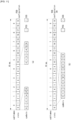
- FIG. 15 illustrates still yet another example of the method for transmitting the synchronization signal to which the method proposed in this specification may be applied.
- FIG. 15 is just for convenience of the description and does not limit the scope of the present disclosure.
- the subframe level cover code may be applied to the synchronization signal in the NB-loT system.
- FIG. 15(a) illustrates an NPSS to which the cover code according to the FDD or TDD is applied and
- FIG. 15(b) illustrates an NSSS to which the cover code according to the FDD or TDD is applied.
- the transmission period of the NPSS is 10 ms and the transmission period of the NSSS is 20 ms.
- [1, 1, 1, ...] may be configured to be used as the subframe level cover code and in the case of the TDD, a subframe level cover code which is different from [1, 1, 1, ...] and has excellent detection performance may be configured to be used.
- a subframe level cover code which is different from [1, 1, 1, ...] and has excellent detection performance may be configured to be used.
- [1, -1, 1, -1, ...] may be configured to be used as the subframe level cover code with respect to the NPSS and/or the NSSS.
- the corresponding method as a simple method which is not high complex for the base station and the UE has an advantage in that the UE detects only the cover code to determine the TDD or the FDD. In this case, the UE may have to detect multiple subframes in order to determine the TDD or the FDD.
- first to fifth embodiments described above may be used in order to distinguish the TDD or the FDD by two or two or more combinations.
- a method for distinguishing the TDD or the FDD by combining methods 2) of the second embodiment and the fourth embodiment may be considered.
- the density (i.e., transmission period) used for the TDD is reduced to a half as compared with the existing density
- the cyclic shift value ⁇ f may be determined by applying the method of second embodiment. That is, when the NSSS occupies one subframe (e.g., subframe #9) every 40 ms (e.g., occupies only 11 symbols among 14 symbols), two cyclic shift values need to be determined.
- the NPBCH may be configured to be transmitted in subframe #9 and the NSSS may be configured to be transmitted in subframe #0. A detailed example thereof is illustrated in FIG. 16 .
- FIG. 16 illustrates still yet another example of the method for transmitting the synchronization signal to which the method proposed in this specification may be applied.
- FIG. 16 is just for convenience of the description and does not limit the scope of the present disclosure. Referring to FIG. 16 , a case where the method of the second embodiment and method 2) of the fourth embodiment are combined and applied is assumed.
- the NSSS may be configured to be transmitted once every four radio frames and the interval from the time when the transmission of the NPSS is terminated up to the time when the transmission of the NSSS is started may be configured differently according to the FDD or the TDD. That is, in distinguishing the type of radio frame structure, a sequence difference of the NSSS may also be considered in addition to the difference in distance between the transmission subframe of the NPSS and the transmission subframe of the NSSS.
- the UE may obtain an error correction effect.
- a method for distinguishing the TDD or the FDD by changing the transmission periods (i.e., densities) of both the NPSS and the NSSS, characteristically increasing the period (i.e., decreasing the density), and changing even respective sequences may also be considered.
- the NPSS is configured to occupy one subframe (e.g., occupies only 11 symbols among 14 symbols of subframe #5) every 10 ms and the NSSS is configured to occupy one subframe (e.g., occupies only 11 symbols among 14 symbols of subframe #9) every 20 ms.
- the NPSS may be configured to occupy one subframe (e.g., occupies only 11 symbols among 14 symbols of subframe #5) every 20 ms and the NSSS may be configured to occupy one subframe (e.g., occupies only 11 symbols among 14 symbols of subframe #9) every 40 ms. Therefore, additionally, the root index and/or cover code of the NPSS may be configured to be changed and the cyclic shift value of the NSSS may be configured to be changed according to the aforementioned method.
- the NPSS is configured to occupy one subframe (e.g., occupies only 11 symbols among 14 symbols of subframe #5) every 10 ms and the NSSS is configured to occupy one subframe (e.g., occupies only 11 symbols among 14 symbols of subframe #9) every 20 ms.
- the NPSS may be configured to occupy one subframe (e.g., occupies only 11 symbols among 14 symbols of subframe #5) every 20 ms and the NSSS may be configured to occupy one subframe (e.g., occupies only 11 symbols among 14 symbols of subframe #5) every 40 ms. Therefore, additionally, the root index and/or cover code of the NPSS may be configured to be changed and the cyclic shift value of the NSSS may be configured to be changed according to the aforementioned method.
- the locations of the subframes occupied by the NPSS and the NSSS in the TDD are the same as each other. A detailed example thereof is illustrated in FIG. 17 .
- FIG. 17 illustrates still yet another example of the method for transmitting the synchronization signal to which the method proposed in this specification may be applied.
- FIG. 17 is just for convenience of the description and does not limit the scope of the present disclosure.
- a scheme of transmitting the NPSS and the NSSS in the case of the FDD and a scheme of transmitting the NPSS and the NSSS in the case of the TDD are configured differently from each other.
- both the NPSS and the NSSS may be transmitted in subframe #5.
- the transmission periods of the NPSS and the NSSS are configured to be different from each other (the transmission period of the NPSS is 2 ms and the transmission period of the NSSS is 4 ms)
- the NPSS and the NSSS may be transmitted not to overlap with each other.
- the downlink subframe may be secured in terms of the TDD.
- the number of downlink subframes is limited in the case of the TDD, this is related to more efficiently performing downlink transmission.
- the NRS may be transmitted in every subframe #9 of the radio frame structure for the TDD, it is advantageous in that the UE may perform the cross-subframe channel estimation for detecting the NPBCH transmitted in subframe #0. Further, as mentioned above, the error correction effect of the UE may also be obtained.
- FIG. 18 is a flowchart of an operation of a UE which performs a cell search procedure by using a synchronization signal in a wireless communication system to which a claimed method proposed in this specification may be applied.
- FIG. 18 is just for convenience of the description and does not limit the scope of the present disclosure.
- a narrowband synchronization signal may mean a synchronization signal (e.g., the NPSS, NSSS, etc.) configured for the NB-loT system and in particular, the base station and/or the UE may transmit/receive the NPSS, the NSSS, and/or the NPBCH according to the embodiments (in particular, method 2 of the fourth embodiment).
- a synchronization signal e.g., the NPSS, NSSS, etc.
- the base station and/or the UE may transmit/receive the NPSS, the NSSS, and/or the NPBCH according to the embodiments (in particular, method 2 of the fourth embodiment).
- the UE receives a narrowband synchronization signal (e.g., NPSS or NSSS) from the base station (step S1805).
- a narrowband synchronization signal e.g., NPSS or NSSS
- the narrowband synchronization signal is transmitted according to the aforementioned method.
- the UE receives the NPSS and the NSSS and the corresponding NPSS and NSSS is transmitted in different subframes.
- the subframe in which the NSSS is transmitted is configured differently from each other according to the type of radio frame structure.
- the NSSS is transmitted in subframe #9 of the radio frame and in the case of the radio frame structure (e.g., the second type of radio frame structure) for the TDD, the NSSS is transmitted in subframe #0 of the radio frame. Further, the NPSS is transmitted in subframe #5 of the radio frame.
- the transmission period (e.g., 20 ms) of the NSSS is configured two times longer than the transmission period (e.g., 10 ms) of the NPSS and the NSSS is transmitted in even-numbered radio frames among multiple radio frames supported by a wireless communication system. Further, as described above, each of the NPSS and the NSSS are transmitted through 11 OFDM symbols in the subframe.
- the UE receives a narrowband broadcast channel (e.g., NPBCH) and a subframe in which a narrowband broadcast channel is transmitted is also configured differently according to the type of radio frame structure.
- a narrowband broadcast channel e.g., NPBCH
- the narrowband broadcast channel is transmitted in subframe #0 of the radio frame and in the case of the radio frame structure for the TDD, the narrowband broadcast channel is transmitted in subframe #9 of the radio frame (e.g., FIG. 14 ).
- the UE may determine the radio frame structure provided by the base station by using a gap between the subframe in which the NPSS is transmitted and the subframe in which the NSSS is transmitted like the aforementioned method.
- the UE performs a cell search procedure for the base station based on the received narrowband synchronization signal.
- the cell search procedure may mean a procedure of acquiring time and frequency synchronization by using the synchronization signal and acquiring a cell ID of the corresponding base station.
- the UE may rapidly determine or confirm the radio frame structure to be provided thereto by using the synchronization signal (e.g., NPSS, NSSS, and/or NPBCH) while performing the initial access procedure.
- the synchronization signal e.g., NPSS, NSSS, and/or NPBCH
- a length 11 cover code of the NPSS used in the radio frame structure (hereinafter, the first type of radio frame structure) for the FDD may be [1, 1, 1, 1, -1, -1, 1, 1, 1, -1, 1].
- a method for distinguishing the type of radio frame structure by configuring the cover code value of the NPSS used in the radio frame structure (hereinafter, the second type of radio frame structure) for the TDD differently from that in the case of the FDD may also be considered.
- the cover code which may be considered in the radio frame structure for the TDD may be configured to have three characteristics described below.
- the cover code having such a characteristic may be determined through two tests described below.
- a method may be considered which the NPSS cover code value of the base station is configured to [1, 1, 1, 1, -1, -1, 1, 1, 1, -1, 1] used in the first type of radio frame structure and the UE compares correlation power values calculated for 2047 cover codes in a receiving step to find a cover code in which a peak power value is configured to be a small value.
- the 2047 cover codes mean 2 11 -1 cover codes other than the cover code used in the first type of radio frame structure in all cover codes having a length of 11. Further the correlation power values may be calculated through several OFDM symbol level differential algorithms.
- the cover codes may be listed in an order in which the peak power values are smaller and 15 top cover codes among the cover codes may be shown in Table 6. That is, Table 6 shows indexes of top 15 cover codes having a small peak power value as a result of the first test.
- the cover code index may mean a value which may be acquired when regarding the cover code as a binary number (in this case, -1 is regarded as 0).
- [-1, -1, -1, -1, -1, -1, -1, -1, -1, -1, -1, -1] may be expressed as cover code index 0 and [1, 1, 1, 1, 1, 1, 1, 1, 1, 1] may be expressed as cover code index 2047.
- cover code index 1699 underlined in Table 6 may mean [1, 1, -1, 1, -1, 1, -1, -1, 1, 1].
- the NPSS cover code value of the base station may be configured to select one of 2048 cover codes and the UE may compare the correlation power values calculated by using the cover code selected above in the receiving step.
- cover codes in which a peak power value (hereinafter, referred to as an A value) compared with the second peak power of the correlation power acquired by using the selected cover code is equal to or larger than a peak power value (hereinafter, referred to as a B value compared with a second peak power of the correlation power acquired by using the cover code (e.g., [1, 1, 1, 1, -1, -1, 1, 1, 1, -1, 1]) used in the first type of radio frame structure.
- a value peak power value
- B value compared with a second peak power of the correlation power acquired by using the cover code
- the peak power value compared with the second peak power may mean a main peak value compared with a side peak for the correlation power values.
- the peak power i.e., main peak
- the second peak power i.e., side peak
- the peak power value compared with the second peak power is 2.
- a case where the peak power value is larger than the second peak power may mean that correlation performance of the corresponding sequence is high.
- cover codes may be determined which satisfy a condition in which the A value is equal to or larger than the B and the cover code in which the peak power value among the cover codes is large may be configured as the cover code for the NPSS of the second type of radio frame structure.
- the cover codes which satisfy the condition in which the A value is equal or larger than the B may be listed in an order in which the peak power values are larger and 15 top cover codes among the cover codes may be shown in Table 7. That is, Table 7 shows indexes of top 15 cover codes having a large peak power value as a result of the second test.
- cover code index 1699 (i.e., [1, 1, -1, 1, -1, 1, -1, -1, 1, 1]) included in 15 top cover codes in the first test is included in 15 top cover codes even in the second test.
- the cover code suitable for the second type of radio frame structure may be cover code index 1699 (i.e., [1, 1, -1, 1, -1, 1, -1, -1, -1, 1, 1]).
- results acquired by calculating the correlation power values for the first and second tests by using topmost cover codes i.e., cover code indexes 2007 and 562 in the result of each test, cover code index 1699 determined to be suitable for the second type of radio frame structure, and the cover code (i.e., cover code index 1949) may be illustrated in FIGS. 19 and 20 , respectively.
- FIG. 19 illustrates an example of a correlation power graph for cover code values of NPSS to which a method proposed in this specification may be applied.
- FIG. 19 is just for convenience of the description and does not limit the scope of the present disclosure.
- the correlation power values may be calculated through several OFDM symbol level differential algorithms based on the scheme of the first test by using the cover codes corresponding to cover code indexes 2007, 562, and 1699 related to the second type of radio frame structure and the cover code used in the first type of radio frame structure.
- cover code indexes 1699 and 2007 have a value close to zero, while cover code index 562 has a peak value close to 0.1 in an inaccurate time sample index.
- cover code index 562 has lower performance than cover code indexes 1699 and 2007. That is, through the graphs of FIG. 19 , it may be derived that cover code index 562 is not included in 15 top cover codes of the first test result.
- FIG. 20 illustrates another example of the correlation power graph for the cover code values of NPSS to which the method proposed in this specification may be applied.
- FIG. 20 is just for convenience of the description and does not limit the scope of the present disclosure.
- the correlation power values may be calculated through several OFDM symbol level differential algorithms based on the scheme of the second test by using the cover codes corresponding to cover code indexes 2007, 562, and 1699 related to the second type of radio frame structure and the cover code used in the first type of radio frame structure.
- cover code indexes 562 and 1699 may have a sharp main peak, while cover code index 2007 may additionally have side peaks at both sides in addition to the main peak.
- cover code index 2007 has lower performance than cover code indexes 526 and 1699. That is, through the graphs of FIG. 20 , it may be derived that cover code index 2007 is not included in 15 top cover codes of the second test result.
- the main peak may mean a largest output (i.e., correlation power) value acquired through several OFDM symbol level differential algorithms and the side peak may mean a largest output value in which a specific range deviates from the main peak.
- the specific range may mean an interval (i.e., a sample within a specific range from a peak value) used for additional computation in performing a next operation at a receiving side after detecting the peak value.
- the specific interval may be configured to ⁇ 16 Ts' and here, Ts' may mean a 240 kHz sampling frequency time unit.
- cover code to be applied to the NPSSS in the second type of radio frame structure [1, 1, -1, 1, -1, 1, -1, -1, 1, 1] (i.e., cover code index 1699) may be configured.
- cover code S(I) to be used for the NPSS in the case of the TDD may be expressed as shown in Table 8.
- [1, 1, -1, 1, -1, 1, -1, -1, -1, 1, 1] selected as described above may be configured to be used for the NPSS of another radio frame structure type (e.g., a third type of radio frame structure of the LTE system or a radio frame structure newly introduced in the NR system) in addition to being used for the NPSS of the second type of radio frame structure.
- the corresponding cover code may be extensively applied even to another signal (e.g., a wake-up signal, a go-to-sleep signal, etc.) other than the NPSS, of course.
- the existing value e.g., 5
- a new value e.g., 6) different therefrom may be applied as the root index value of the sequence (e.g., ZC sequence) of the NPSS.
- the gap (i.e., a subframe gap) between the NPSS and the NSSS may be configured to be generated according to the type of radio frame structure. For example, a gap between the time when the transmission of the NPSS is terminated and the time when the transmission of the NSSS is started may be configured to four subframes in the case of the first type of radio frame structure, while the gap may be configured to five subframes in the case of the second type of radio frame structure.
- the method for changing the transmission subframe locations of the NPSS and the NSSS in order to differently configure the gap between the NPSS and the NSSS may also be applied to the NPSS and the NSSS configurations of the second type of radio frame structure.
- the NPSS of the existing NBI-IoT system (e.g., Rel. 13 NB-IoT system) is designed to occupy 11 OFDM symbols and 11 subcarriers.
- FIG. 21 illustrates a resource region occupied by NPSS of an existing NB-loT system.
- the NPSS is configured to occupy 11 OFDM symbols from OFDM symbol #3 to OFDM symbol #13 in the time domain and occupy 11 subcarriers from subcarrier #0 to subcarrier #10 in the frequency domain.
- the NPSS designed as illustrated in FIG. 21 may have an error which is as large as a maximum of ⁇ 25.5 kHz even though a frequency offset and an additional raster offset due to an oscillator error are considered.
- FIG. 22 A detailed example thereof is illustrated in FIG. 22 .
- FIG. 22 illustrates one example of a frequency offset for the NPSS of the existing NB-loT system.
- the bandwidth of the center frequency is configured to be small (e.g., 900 MHz) and the NPSS occupies 11 subcarriers (i.e., 165 kHz).
- the frequency offset may be 20 ppm and the additional raster offset may be ⁇ 7.5 kHz.
- the resource region occupied by the NPSS does not deviate from an analog filter band (e.g., 240 kHz).
- an analog filter band e.g., 240 kHz.
- the NPSS designed as illustrated in FIG. 21 may have an error which is as large as a maximum of ⁇ 59.5 kHz when the frequency offset and the additional raster offset due to the oscillator error are considered.
- FIG. 23 A detailed example thereof is illustrated in FIG. 23 .
- FIG. 23 illustrates another example of the frequency offset for the NPSS of the existing NB-loT system.
- the bandwidth of the center frequency is configured to be large (e.g., 2.6 GHz) and the NPSS occupies 11 subcarriers (i.e., 165 kHz).
- the frequency offset may be 20 ppm and the additional raster offset may be ⁇ 7.5 kHz.
- this specification proposes a method for configuring the number of subcarriers occupied by the NPSS to be changed to 11 - (K 1 + K 2 ) from the existing 11 subcarriers and used according to the center frequency value in which the NB-loT system is operated.
- K 1 and K 2 may mean integers which satisfy 0 ⁇ K 1 + K 2 ⁇ 11, 0 ⁇ K 1 ⁇ 11, and 0 ⁇ K 2 ⁇ 11.
- K 1 represents the number of subcarriers which may be excluded from a low frequency side
- K 2 represents the number of subcarrier which may be excluded from a high frequency side.
- the base station since it is assumed that the base station basically knows information on the center frequency, the base station may be configured to select the pre-promised (or configured or defined) K 1 and K 2 values and transmit the NPSS according to the center frequency value. Further, since it is assumed that the UE currently knows information on a band in which a cell which the UE desires to access is disposed, the UE may be configured to select the pre-promised K 1 and K 2 values and detect the NPSS according to the center frequency value which may exist in the corresponding band.
- Table 9 shows examples of a maximum frequency offset according to the center frequency value, the pre-promised K 1 and K 2 values, and the number of subcarriers occupied by the NPSS according thereto.
- the NPSS sequence may be mapped through the following methods.
- mapping the remaining sequences may mean mapping 0 to the excluded REs and mapping the existing sequence value to the REs which are not excluded. An example therefor may be illustrated in FIG. 24 .
- FIG. 24 illustrates one example of an NPSS sequence mapping method to which a method proposed in this specification may be applied.
- FIG. 24 is just for convenience of the description and does not limit the scope of the present disclosure.
- K 1 applied at the low frequency side is configured to 2 and K 2 applied at the high frequency side is configured to 2.
- the length of the NPSS sequence may be changed to 7 (i.e., 11 - 4) and a length 7 sequence may be mapped to 7 subcarriers from subcarrier #2 to subcarrier #8.
- '0' other than the existing sequence value may be mapped to the RE to which the sequence is not mapped.
- the remaining sequences may be configured to be mapped by excluding K 1 + K 2 REs from any one of the low frequency or the high frequency.
- the remaining sequences may be mapped from subframe #0 to subframe #6 or mapped from subframe #4 to subframe #10.
- a feature of the corresponding method is that the sequence is generated by using root index 5 at the time of initially generating the Zadoff-Chu sequence, but a sequence which is actually mapped to the resource corresponds to a sequence which is as large as length 11 - (K 1 + K 2 ) among the sequences.
- a method for generating a length 11 - -(K 1 + K 2 ) Zadoff-Chu sequence for the NPSS instead of the existing length 11 Zadoff-Chu sequence and mapping the generated Zadoff-Chu sequence to the RE corresponding to the subcarrier which may be occupied by the NPSS may be considered. Due to characteristics of the Zadoff-Chu sequence constituting the NPSS, a sequence having an odd-number length may have excellent performance and the root index may be preferably selected as a medium number of the sequence length.
- K 1 when the center frequency is 2.6 GHz, the maximum frequency offset is ⁇ 59.5 kHz, K 1 may be configured to 2 and K 2 may be configured to 1 or 2.
- An example therefor may be illustrated in FIG. 25 .
- FIG. 25 illustrates another example of the NPSS sequence mapping method to which the method proposed in this specification may be applied.
- FIG. 25 is just for convenience of the description and does not limit the scope of the present disclosure.
- K 1 applied at the low frequency side is configured to 2 and K 2 applied at the high frequency side is configured to 2.
- a length 7 Zadoff-Chu sequence generated for the NPSS may be used and the corresponding sequence may be mapped to 7 subcarriers from subcarrier #2 to subcarrier #8.
- performance of a sequence which is a Zadoff-Chu sequence having a shorter length, but uses the entire sequence may be more excellent than the performance of a sequence which generates the length 11 Zadoff-Chu sequence and uses a sequence from which both or one side is excluded.
- FIG. 26 illustrates one example of NPSS to which a method proposed in this specification may be applied.
- FIG. 26 is just for convenience of the description and does not limit the scope of the present disclosure.
- the NPSS does not deviate from the analog filter band (i.e., 240 kHz). That is, when K 1 and K 2 are selected as 2, the subcarrier to which the NPSS is mapped may exist in the 240 kHz band in spite of considering the maximum error (e.g., ⁇ 59.5 kHz).
- power boosting may be made at the time of transmitting the NPSS as large as the number of REs reduced through the methods (i.e., K 1 + K 2 ).
- a power boosting effect corresponding to the reduced REs may be expected, which may be applied to the NPSS.
- a method for changing the subcarrier spacing for the NPSS instead of changing the number of subcarriers occupied by the NPSS according to the center frequency like the method described above may be considered. That is, instead of using the 15 kHz subcarrier spacing like the existing NPSS, the NPSS may be configured to be transmitted by reducing the subcarrier spacing at a timing (e.g., within 1 ms or within one subframe) for transmitting the NPSS when the center frequency is high (e.g., 2.6 GHz).
- reducing the subcarrier spacing may mean increasing a symbol length. An example thereof is illustrated in FIG. 27 .
- FIG. 27 illustrates yet another example of the NPSS sequence mapping method to which the method proposed in this specification may be applied.
- FIG. 27 is just for convenience of the description and does not limit the scope of the present disclosure.
- the NPSS is transmitted by using 7.5 kHz acquired by reducing the subcarrier spacing to a half from 15 kHz (i.e., the subframe interval in the existing LTE).
- the symbol length increases twice.
- first two symbols may be configured to be emptied in order to guarantee the control region of the existing LTE system.
- the length 11 Zadoff-Chu sequence and the root index value may be maintained as they are, but the cover code used over 11 symbols needs to be changed to be used over 5 symbols.
- a change method may be configured to cut and use up to 5 existing cover codes (cover codes configured according to length 11) from the first or newly introduce and use a cover code corresponding to length 5.
- FIG. 28 illustrates another example of the frequency offset for the NPSS to which the method proposed in this specification may be applied.
- FIG. 28 is just for convenience of the description and does not limit the scope of the present disclosure.
- the NPSS does not deviate from the analog filter band (i.e., 240 kHz) in the band in which the center frequency is 2.6 GHz.
- FIG. 29 illustrates a block diagram of a wireless communication device to which methods proposed by this specification may be applied.
- a wireless communication system includes a base station 2910 and multiple UEs 2910 positioned within an area of the base station 2920.
- the base station 2910 includes a processor 2911, a memory 2912, and a radio frequency (RF) unit 2913.
- the processor 2911 implements a function, a process, and/or a method which are proposed in FIGS. 1 to 28 above.
- the layers of the wireless interface protocol may be implemented by the processor 2911.
- the memory 2912 is connected with the processor 2911 to store various pieces of information for driving the processor 2911.
- the RF unit 2913 is connected with the processor 2911 to transmit and/or receive a radio signal.
- the UE 2920 includes a processor 2921, a memory 2922, and an RF unit 2923.
- the processor 2921 implements a function, a process, and/or a method which are proposed in FIGS. 1 to 28 above.
- the layers of the wireless interface protocol may be implemented by the processor 2921.
- the memory 2922 is connected with the processor 2921 to store various pieces of information for driving the processor 2921.
- the RF unit 2923 is connected with the processor 2921 to transmit and/or receive a radio signal.
- the memories 2912 and 2922 may be positioned inside or outside the processors 2911 and 2921 and connected with the processors 2911 and 2921 by various well-known means. Further, the base station 2910 and/or the UE 2920 may have a single antenna or multiple antennas.
- FIG. 30 illustrates a block diagram of a communication device according to an embodiment of the present disclosure.
- FIG. 30 is a diagram more specifically illustrating the UE of FIG. 29 above.
- the UE may be configured to include a processor (or a digital signal processor (DSP) 3010, an RF module (or RF unit) 3035, a power management module 3005, an antenna 3040, a battery 3055, a display 3015, a keypad 3020, a memory 3030, a subscriber identification module (SIM) card 3025 (This component is optional), a speaker 3045, and a microphone 3050.
- the UE may also include a single antenna or multiple antennas.
- the processor 3010 implements a function, a process, and/or a method which are proposed in FIGS. 1 to 28 above. Layers of a wireless interface protocol may be implemented by the processor 3010.
- the memory 3030 is connected with the processor 3010 to store information related to an operation of the processor 3010.
- the memory 3030 may be positioned inside or outside the processor 3010 and connected with the processor 3010 by various well-known means.
- a user inputs command information such as a telephone number or the like by, for example, pressing (or touching) a button on the keypad 3020 or by voice activation using the microphone 3050.
- the processor 3010 receives such command information and processes to perform appropriate functions including dialing a telephone number. Operational data may be extracted from the SIM card 3025 or the memory 3030. In addition, the processor 3010 may display command information or drive information on the display 3015 for the user to recognize and for convenience.
- the RF module 3035 is connected with the processor 3010 to transmit and/or receive an RF signal.
- the processor 3010 transfers the command information to the RF module 3035 to initiate communication, for example, to transmit wireless signals constituting voice communication data.
- the RF module 3035 is constituted by a receiver and a transmitter for receiving and transmitting the wireless signals.
- the antenna 3040 functions to transmit and receive the wireless signals.
- the RF module 3035 may transfer the signal for processing by the processor 3010 and convert the signal to a baseband.
- the processed signal may be converted into to audible or readable information output via the speaker 3045.
- an embodiment of the present disclosure may be implemented by various means, for example, hardware, firmware, software and the combination thereof.
- an embodiment of the present disclosure may be implemented by one or more application specific integrated circuits (ASICs), digital signal processors (DSPs), digital signal processing devices (DSPDs), programmable logic devices (PLDs), field programmable gate arrays (FPGAs), a processor, a controller, a micro controller, a micro processor, and the like.
- ASICs application specific integrated circuits
- DSPs digital signal processors
- DSPDs digital signal processing devices
- PLDs programmable logic devices
- FPGAs field programmable gate arrays
- an embodiment of the present disclosure may be implemented in a form such as a module, a procedure, a function, and so on that performs the functions or operations described so far.
- Software codes may be stored in the memory, and driven by the processor.
- the memory may be located interior or exterior to the processor, and may exchange data with the processor with various known means.
- the method for transmitting/receiving the signal in the wireless communication system of the present disclosure which supports NB-IoT is described primarily with an example applied to a 3GPP LTE/LTE-A system, but the method can be applied to various wireless communication systems including the new RAT (NR) system in addition to the 3GPP LTE/LTE-A system.
- NR new RAT
Applications Claiming Priority (4)
| Application Number | Priority Date | Filing Date | Title |
|---|---|---|---|
| US201762523219P | 2017-06-21 | 2017-06-21 | |
| US201762536972P | 2017-07-25 | 2017-07-25 | |
| US201762554513P | 2017-09-05 | 2017-09-05 | |
| PCT/KR2018/007039 WO2018236165A1 (ko) | 2017-06-21 | 2018-06-21 | 무선 통신 시스템에서 동기 신호를 송수신하는 방법 및 이를 위한 장치 |
Publications (3)
| Publication Number | Publication Date |
|---|---|
| EP3644530A1 EP3644530A1 (en) | 2020-04-29 |
| EP3644530A4 EP3644530A4 (en) | 2020-12-09 |
| EP3644530B1 true EP3644530B1 (en) | 2023-11-15 |
Family
ID=64737326
Family Applications (1)
| Application Number | Title | Priority Date | Filing Date |
|---|---|---|---|
| EP18820238.6A Active EP3644530B1 (en) | 2017-06-21 | 2018-06-21 | Method and device for transmitting or receiving synchronization signal in wireless communication system |
Country Status (6)
| Country | Link |
|---|---|
| US (4) | US10925021B2 (zh) |
| EP (1) | EP3644530B1 (zh) |
| JP (2) | JP7210481B2 (zh) |
| KR (2) | KR102017238B1 (zh) |
| CN (2) | CN110785951B (zh) |
| WO (1) | WO2018236165A1 (zh) |
Families Citing this family (13)
| Publication number | Priority date | Publication date | Assignee | Title |
|---|---|---|---|---|
| WO2018174600A1 (ko) * | 2017-03-22 | 2018-09-27 | 엘지전자 주식회사 | 무선 통신 시스템에서 단말의 동작 방법 및 이를 지원하는 장치 |
| CN110785951B (zh) | 2017-06-21 | 2021-05-04 | Lg 电子株式会社 | 无线通信系统中发送/接收同步信号的方法及其装置 |
| CN109391453B (zh) * | 2017-08-11 | 2022-07-12 | 夏普株式会社 | 用户设备、基站和相关方法 |
| WO2020145721A1 (ko) * | 2019-01-11 | 2020-07-16 | 엘지전자 주식회사 | Nr v2x의 사이드링크 harq 피드백 |
| KR20210007356A (ko) * | 2019-07-11 | 2021-01-20 | 삼성전자주식회사 | 전자 장치의 동작 방법 및 전자 장치에 포함된 신호 처리 장치 |
| KR102162962B1 (ko) | 2019-10-30 | 2020-10-07 | 주식회사 새로운길 | 휀스 |
| KR102085194B1 (ko) | 2020-01-06 | 2020-03-05 | 주식회사 새로운길 | 휀스 |
| KR20220009316A (ko) | 2020-07-15 | 2022-01-24 | 주식회사 새로운길 | 휀스 |
| KR20220038905A (ko) | 2020-09-21 | 2022-03-29 | 주식회사 새로운길 | 휀스 |
| KR20220094088A (ko) | 2020-12-28 | 2022-07-05 | 서울특별시 | 회전 체결구를 구비한 휀스 |
| KR20220121101A (ko) | 2021-02-24 | 2022-08-31 | 주식회사 새로운길 | 횡대 회동식 휀스 |
| CN114095324B (zh) * | 2021-11-09 | 2023-09-12 | 湖南省时空基准科技有限公司 | 窄带数据广播的成帧方法及其设备 |
| CN115314350B (zh) * | 2022-08-15 | 2023-04-18 | 北京神经元网络技术有限公司 | 无线蜂窝小区搜索同步方法、装置、设备及存储介质 |
Family Cites Families (21)
| Publication number | Priority date | Publication date | Assignee | Title |
|---|---|---|---|---|
| KR101253197B1 (ko) * | 2010-03-26 | 2013-04-10 | 엘지전자 주식회사 | 참조신호 수신 방법 및 사용자기기, 참조신호 전송 방법 및 기지국 |
| US8923197B2 (en) * | 2011-06-01 | 2014-12-30 | Samsung Electronics Co., Ltd. | Methods and apparatus to transmit and receive synchronization signal and system information in a wireless communication system |
| US9497719B2 (en) * | 2012-01-29 | 2016-11-15 | Lg Electronics Inc. | User equipment and method for receiving synchronization signals, and base station and method for transmitting synchronization signals |
| WO2013133682A1 (ko) * | 2012-03-09 | 2013-09-12 | 엘지전자 주식회사 | 참조 신호 설정 방법 및 장치 |
| KR20140129983A (ko) * | 2013-04-30 | 2014-11-07 | 인텔렉추얼디스커버리 주식회사 | 스몰셀 환경에 적합한 새로운 tdd 동기채널 서브프레임 구성 |
| WO2015200667A1 (en) * | 2014-06-27 | 2015-12-30 | Intel IP Corporation | Method and apparatus of ue and enb for mtc with narrowband deployment |
| EP3206446B1 (en) * | 2014-10-07 | 2019-08-07 | LG Electronics Inc. | Method for transmitting synchronization signal for device-to-device communication in wireless communication system and apparatus therefor |
| US10454606B2 (en) * | 2015-07-22 | 2019-10-22 | Samsung Electronics Co., Ltd. | Method for operating IoT in cellular system and system therefor |
| WO2017014613A1 (ko) | 2015-07-23 | 2017-01-26 | 삼성전자 주식회사 | 무선 셀룰러 통신 시스템에서 협대역 신호 전송을 위한 방법 및 장치 |
| US10863459B2 (en) * | 2015-07-24 | 2020-12-08 | Apple Inc. | Synchronization signals and channel structure for narrowband LTE deployments |
| WO2017039739A1 (en) * | 2015-09-02 | 2017-03-09 | Intel IP Corporation | Methods and apparatuses for channel estimation for nb-pbch in nb-lte systems |
| CN106488509B (zh) * | 2015-09-02 | 2021-10-19 | 中兴通讯股份有限公司 | 一种系统消息传输方法及装置 |
| WO2017048105A1 (ko) * | 2015-09-15 | 2017-03-23 | 엘지전자(주) | 무선 통신 시스템에서의 셀 탐색 방법 및 이를 위한 장치 |
| WO2017052326A1 (en) | 2015-09-24 | 2017-03-30 | Lg Electronics Inc. | Method and apparatus for handling various iot network access in wireless communication system |
| US10728078B2 (en) * | 2015-10-19 | 2020-07-28 | Lg Electronics Inc. | Method and user equipment for receiving downlink signal, and method and base station for transmitting downlink signal |
| WO2017078802A1 (en) * | 2015-11-06 | 2017-05-11 | Intel IP Corporation | Synchronization signal design for narrowband internet of things communications |
| EP3605937B1 (en) * | 2015-12-18 | 2021-05-12 | Telefonaktiebolaget LM Ericsson (publ) | Transmitting and receiving narrowband synchronization signals |
| CN106936756B (zh) * | 2015-12-31 | 2019-04-12 | 中兴通讯股份有限公司 | 同步信号的传输方法、装置及系统 |
| ES2790223T3 (es) * | 2016-03-16 | 2020-10-27 | Ericsson Telefon Ab L M | Espacio de búsqueda común (CSS) para avisar a dispositivos de la NB-IoT |
| CN106160916B (zh) * | 2016-08-25 | 2019-04-23 | 上海创远仪器技术股份有限公司 | 一种NB-IoT小区搜索装置及其搜索方法 |
| CN110785951B (zh) * | 2017-06-21 | 2021-05-04 | Lg 电子株式会社 | 无线通信系统中发送/接收同步信号的方法及其装置 |
-
2018
- 2018-06-21 CN CN201880040970.0A patent/CN110785951B/zh active Active
- 2018-06-21 WO PCT/KR2018/007039 patent/WO2018236165A1/ko unknown
- 2018-06-21 KR KR1020180071660A patent/KR102017238B1/ko active IP Right Grant
- 2018-06-21 CN CN202110411652.4A patent/CN113301536B/zh active Active
- 2018-06-21 JP JP2019569869A patent/JP7210481B2/ja active Active
- 2018-06-21 EP EP18820238.6A patent/EP3644530B1/en active Active
-
2019
- 2019-08-26 KR KR1020190104322A patent/KR102116965B1/ko active IP Right Grant
- 2019-12-11 US US16/711,024 patent/US10925021B2/en active Active
- 2019-12-17 US US16/717,646 patent/US10986597B2/en active Active
-
2021
- 2021-03-26 US US17/214,183 patent/US11570734B2/en active Active
-
2022
- 2022-11-18 JP JP2022185057A patent/JP2023015350A/ja active Pending
-
2023
- 2023-01-23 US US18/158,172 patent/US11832200B2/en active Active
Also Published As
| Publication number | Publication date |
|---|---|
| JP7210481B2 (ja) | 2023-01-23 |
| US20200196256A1 (en) | 2020-06-18 |
| CN110785951A (zh) | 2020-02-11 |
| CN110785951B (zh) | 2021-05-04 |
| KR102116965B1 (ko) | 2020-06-01 |
| WO2018236165A1 (ko) | 2018-12-27 |
| JP2023015350A (ja) | 2023-01-31 |
| EP3644530A4 (en) | 2020-12-09 |
| US11570734B2 (en) | 2023-01-31 |
| EP3644530A1 (en) | 2020-04-29 |
| US10986597B2 (en) | 2021-04-20 |
| CN113301536B (zh) | 2023-09-12 |
| US20200205098A1 (en) | 2020-06-25 |
| KR102017238B1 (ko) | 2019-09-02 |
| KR20180138556A (ko) | 2018-12-31 |
| KR20190102163A (ko) | 2019-09-03 |
| JP2020524941A (ja) | 2020-08-20 |
| CN113301536A (zh) | 2021-08-24 |
| US20230189173A1 (en) | 2023-06-15 |
| US11832200B2 (en) | 2023-11-28 |
| US20210235400A1 (en) | 2021-07-29 |
| US10925021B2 (en) | 2021-02-16 |
Similar Documents
| Publication | Publication Date | Title |
|---|---|---|
| EP3644530B1 (en) | Method and device for transmitting or receiving synchronization signal in wireless communication system | |
| US11160094B2 (en) | Method for transmitting/receiving data in wireless communication system supporting narrow-band internet of things, and apparatus for same | |
| US11115144B2 (en) | Cell search method in wireless communication system and apparatus therefor | |
| US11039460B2 (en) | Method for transmitting/receiving data in wireless communication system supporting Narrow Band Internet-of-Things and device therefor | |
| US20200186321A1 (en) | Method for transmitting or receiving signal in wireless communication system, and device therefor | |
| KR102243662B1 (ko) | 무선 통신 시스템에서 d2d(device-to-device) 통신을 위한 동기화 신호 전송 방법 및 이를 위한 장치 | |
| US11096222B2 (en) | Method for transmitting and receiving random access preamble in wireless communication system and apparatus therefor | |
| US9967842B2 (en) | Method for detecting synchronization signal for device-to-device (D2D) communication in wireless communication system and apparatus therefor | |
| EP3550922A1 (en) | Method and apparatus for transmitting and receiving random access preambles in a wireless communication system | |
| US10721777B2 (en) | Method and apparatus for transmitting a random access preamble in a narrow band IoT system supporting time division duplexing | |
| EP3522433B1 (en) | Method for transmitting and receiving system information in wireless communication system supporting tdd narrowband and apparatus therefor | |
| EP3780462B1 (en) | Method and apparatus for transmitting or receiving system information in wireless communication system supporting tdd narrowband | |
| US20210314995A1 (en) | Method for transmitting or receiving mpdcch in wireless communication system supporting mtc, and apparatus therefor | |
| EP3664563B1 (en) | Method for transmitting random access preamble in narrowband iot system supporting time division duplexing and apparatus therefor | |
| US11844111B2 (en) | Method for transmitting message for execution of random access procedure in wireless communication system and apparatus therefor | |
| US11617097B2 (en) | Method for performing measurement by using RSS in wireless communication system and apparatus therefor |
Legal Events
| Date | Code | Title | Description |
|---|---|---|---|
| STAA | Information on the status of an ep patent application or granted ep patent |
Free format text: STATUS: THE INTERNATIONAL PUBLICATION HAS BEEN MADE |
|
| PUAI | Public reference made under article 153(3) epc to a published international application that has entered the european phase |
Free format text: ORIGINAL CODE: 0009012 |
|
| STAA | Information on the status of an ep patent application or granted ep patent |
Free format text: STATUS: REQUEST FOR EXAMINATION WAS MADE |
|
| 17P | Request for examination filed |
Effective date: 20200120 |
|
| AK | Designated contracting states |
Kind code of ref document: A1 Designated state(s): AL AT BE BG CH CY CZ DE DK EE ES FI FR GB GR HR HU IE IS IT LI LT LU LV MC MK MT NL NO PL PT RO RS SE SI SK SM TR |
|
| AX | Request for extension of the european patent |
Extension state: BA ME |
|
| DAV | Request for validation of the european patent (deleted) | ||
| DAX | Request for extension of the european patent (deleted) | ||
| A4 | Supplementary search report drawn up and despatched |
Effective date: 20201111 |
|
| RIC1 | Information provided on ipc code assigned before grant |
Ipc: H04B 7/26 20060101ALI20201105BHEP Ipc: H04W 56/00 20090101ALN20201105BHEP Ipc: H04J 11/00 20060101AFI20201105BHEP Ipc: H04L 5/00 20060101ALN20201105BHEP |
|
| STAA | Information on the status of an ep patent application or granted ep patent |
Free format text: STATUS: EXAMINATION IS IN PROGRESS |
|
| 17Q | First examination report despatched |
Effective date: 20220520 |
|
| GRAP | Despatch of communication of intention to grant a patent |
Free format text: ORIGINAL CODE: EPIDOSNIGR1 |
|
| STAA | Information on the status of an ep patent application or granted ep patent |
Free format text: STATUS: GRANT OF PATENT IS INTENDED |
|
| RIC1 | Information provided on ipc code assigned before grant |
Ipc: H04W 56/00 20090101ALN20230825BHEP Ipc: H04L 5/00 20060101ALN20230825BHEP Ipc: H04B 7/26 20060101ALI20230825BHEP Ipc: H04J 11/00 20060101AFI20230825BHEP |
|
| GRAS | Grant fee paid |
Free format text: ORIGINAL CODE: EPIDOSNIGR3 |
|
| INTG | Intention to grant announced |
Effective date: 20230912 |
|
| GRAA | (expected) grant |
Free format text: ORIGINAL CODE: 0009210 |
|
| STAA | Information on the status of an ep patent application or granted ep patent |
Free format text: STATUS: THE PATENT HAS BEEN GRANTED |
|
| AK | Designated contracting states |
Kind code of ref document: B1 Designated state(s): AL AT BE BG CH CY CZ DE DK EE ES FI FR GB GR HR HU IE IS IT LI LT LU LV MC MK MT NL NO PL PT RO RS SE SI SK SM TR |
|
| REG | Reference to a national code |
Ref country code: CH Ref legal event code: EP Ref country code: GB Ref legal event code: FG4D |
|
| REG | Reference to a national code |
Ref country code: DE Ref legal event code: R096 Ref document number: 602018061207 Country of ref document: DE |
|
| REG | Reference to a national code |
Ref country code: IE Ref legal event code: FG4D |
|
| REG | Reference to a national code |
Ref country code: LT Ref legal event code: MG9D |
|
| REG | Reference to a national code |
Ref country code: NL Ref legal event code: MP Effective date: 20231115 |
|
| PG25 | Lapsed in a contracting state [announced via postgrant information from national office to epo] |
Ref country code: GR Free format text: LAPSE BECAUSE OF FAILURE TO SUBMIT A TRANSLATION OF THE DESCRIPTION OR TO PAY THE FEE WITHIN THE PRESCRIBED TIME-LIMIT Effective date: 20240216 |
|
| PG25 | Lapsed in a contracting state [announced via postgrant information from national office to epo] |
Ref country code: IS Free format text: LAPSE BECAUSE OF FAILURE TO SUBMIT A TRANSLATION OF THE DESCRIPTION OR TO PAY THE FEE WITHIN THE PRESCRIBED TIME-LIMIT Effective date: 20240315 |
|
| PG25 | Lapsed in a contracting state [announced via postgrant information from national office to epo] |
Ref country code: LT Free format text: LAPSE BECAUSE OF FAILURE TO SUBMIT A TRANSLATION OF THE DESCRIPTION OR TO PAY THE FEE WITHIN THE PRESCRIBED TIME-LIMIT Effective date: 20231115 |
|
| REG | Reference to a national code |
Ref country code: AT Ref legal event code: MK05 Ref document number: 1632714 Country of ref document: AT Kind code of ref document: T Effective date: 20231115 |
|
| PG25 | Lapsed in a contracting state [announced via postgrant information from national office to epo] |
Ref country code: NL Free format text: LAPSE BECAUSE OF FAILURE TO SUBMIT A TRANSLATION OF THE DESCRIPTION OR TO PAY THE FEE WITHIN THE PRESCRIBED TIME-LIMIT Effective date: 20231115 |
|
| PG25 | Lapsed in a contracting state [announced via postgrant information from national office to epo] |
Ref country code: AT Free format text: LAPSE BECAUSE OF FAILURE TO SUBMIT A TRANSLATION OF THE DESCRIPTION OR TO PAY THE FEE WITHIN THE PRESCRIBED TIME-LIMIT Effective date: 20231115 |
|
| PG25 | Lapsed in a contracting state [announced via postgrant information from national office to epo] |
Ref country code: ES Free format text: LAPSE BECAUSE OF FAILURE TO SUBMIT A TRANSLATION OF THE DESCRIPTION OR TO PAY THE FEE WITHIN THE PRESCRIBED TIME-LIMIT Effective date: 20231115 |
|
| PG25 | Lapsed in a contracting state [announced via postgrant information from national office to epo] |
Ref country code: NL Free format text: LAPSE BECAUSE OF FAILURE TO SUBMIT A TRANSLATION OF THE DESCRIPTION OR TO PAY THE FEE WITHIN THE PRESCRIBED TIME-LIMIT Effective date: 20231115 Ref country code: LT Free format text: LAPSE BECAUSE OF FAILURE TO SUBMIT A TRANSLATION OF THE DESCRIPTION OR TO PAY THE FEE WITHIN THE PRESCRIBED TIME-LIMIT Effective date: 20231115 Ref country code: IS Free format text: LAPSE BECAUSE OF FAILURE TO SUBMIT A TRANSLATION OF THE DESCRIPTION OR TO PAY THE FEE WITHIN THE PRESCRIBED TIME-LIMIT Effective date: 20240315 Ref country code: GR Free format text: LAPSE BECAUSE OF FAILURE TO SUBMIT A TRANSLATION OF THE DESCRIPTION OR TO PAY THE FEE WITHIN THE PRESCRIBED TIME-LIMIT Effective date: 20240216 Ref country code: ES Free format text: LAPSE BECAUSE OF FAILURE TO SUBMIT A TRANSLATION OF THE DESCRIPTION OR TO PAY THE FEE WITHIN THE PRESCRIBED TIME-LIMIT Effective date: 20231115 Ref country code: BG Free format text: LAPSE BECAUSE OF FAILURE TO SUBMIT A TRANSLATION OF THE DESCRIPTION OR TO PAY THE FEE WITHIN THE PRESCRIBED TIME-LIMIT Effective date: 20240215 Ref country code: AT Free format text: LAPSE BECAUSE OF FAILURE TO SUBMIT A TRANSLATION OF THE DESCRIPTION OR TO PAY THE FEE WITHIN THE PRESCRIBED TIME-LIMIT Effective date: 20231115 Ref country code: PT Free format text: LAPSE BECAUSE OF FAILURE TO SUBMIT A TRANSLATION OF THE DESCRIPTION OR TO PAY THE FEE WITHIN THE PRESCRIBED TIME-LIMIT Effective date: 20240315 |