EP3605937B1 - Transmitting and receiving narrowband synchronization signals - Google Patents
Transmitting and receiving narrowband synchronization signals Download PDFInfo
- Publication number
- EP3605937B1 EP3605937B1 EP19196951.8A EP19196951A EP3605937B1 EP 3605937 B1 EP3605937 B1 EP 3605937B1 EP 19196951 A EP19196951 A EP 19196951A EP 3605937 B1 EP3605937 B1 EP 3605937B1
- Authority
- EP
- European Patent Office
- Prior art keywords
- pss
- sss
- subframes
- frame
- network node
- Prior art date
- Legal status (The legal status is an assumption and is not a legal conclusion. Google has not performed a legal analysis and makes no representation as to the accuracy of the status listed.)
- Active
Links
- 238000013507 mapping Methods 0.000 claims description 38
- 238000004891 communication Methods 0.000 claims description 37
- 238000000034 method Methods 0.000 claims description 22
- 230000005540 biological transmission Effects 0.000 description 48
- 238000012545 processing Methods 0.000 description 30
- 238000010586 diagram Methods 0.000 description 13
- 125000004122 cyclic group Chemical group 0.000 description 8
- 238000001514 detection method Methods 0.000 description 6
- 238000004590 computer program Methods 0.000 description 4
- 238000013461 design Methods 0.000 description 4
- 238000012544 monitoring process Methods 0.000 description 3
- 230000003287 optical effect Effects 0.000 description 3
- 238000001228 spectrum Methods 0.000 description 3
- 230000010267 cellular communication Effects 0.000 description 2
- 238000011161 development Methods 0.000 description 2
- 238000005516 engineering process Methods 0.000 description 2
- 230000007274 generation of a signal involved in cell-cell signaling Effects 0.000 description 2
- 238000005259 measurement Methods 0.000 description 2
- 238000012986 modification Methods 0.000 description 2
- 230000004048 modification Effects 0.000 description 2
- 238000000926 separation method Methods 0.000 description 2
- 101000642811 Oryza sativa subsp. indica Soluble starch synthase 1, chloroplastic/amyloplastic Proteins 0.000 description 1
- 238000013459 approach Methods 0.000 description 1
- 230000001419 dependent effect Effects 0.000 description 1
- 230000006870 function Effects 0.000 description 1
- 230000003993 interaction Effects 0.000 description 1
- 230000007774 longterm Effects 0.000 description 1
- 238000005070 sampling Methods 0.000 description 1
Images


Classifications
-
- H—ELECTRICITY
- H04—ELECTRIC COMMUNICATION TECHNIQUE
- H04W—WIRELESS COMMUNICATION NETWORKS
- H04W56/00—Synchronisation arrangements
- H04W56/001—Synchronization between nodes
-
- H—ELECTRICITY
- H04—ELECTRIC COMMUNICATION TECHNIQUE
- H04L—TRANSMISSION OF DIGITAL INFORMATION, e.g. TELEGRAPHIC COMMUNICATION
- H04L27/00—Modulated-carrier systems
- H04L27/26—Systems using multi-frequency codes
- H04L27/2601—Multicarrier modulation systems
- H04L27/2602—Signal structure
- H04L27/261—Details of reference signals
- H04L27/2613—Structure of the reference signals
-
- H—ELECTRICITY
- H04—ELECTRIC COMMUNICATION TECHNIQUE
- H04J—MULTIPLEX COMMUNICATION
- H04J11/00—Orthogonal multiplex systems, e.g. using WALSH codes
- H04J11/0069—Cell search, i.e. determining cell identity [cell-ID]
- H04J11/0073—Acquisition of primary synchronisation channel, e.g. detection of cell-ID within cell-ID group
-
- H—ELECTRICITY
- H04—ELECTRIC COMMUNICATION TECHNIQUE
- H04J—MULTIPLEX COMMUNICATION
- H04J11/00—Orthogonal multiplex systems, e.g. using WALSH codes
- H04J11/0069—Cell search, i.e. determining cell identity [cell-ID]
- H04J11/0076—Acquisition of secondary synchronisation channel, e.g. detection of cell-ID group
-
- H—ELECTRICITY
- H04—ELECTRIC COMMUNICATION TECHNIQUE
- H04L—TRANSMISSION OF DIGITAL INFORMATION, e.g. TELEGRAPHIC COMMUNICATION
- H04L5/00—Arrangements affording multiple use of the transmission path
- H04L5/003—Arrangements for allocating sub-channels of the transmission path
- H04L5/0048—Allocation of pilot signals, i.e. of signals known to the receiver
-
- H—ELECTRICITY
- H04—ELECTRIC COMMUNICATION TECHNIQUE
- H04W—WIRELESS COMMUNICATION NETWORKS
- H04W56/00—Synchronisation arrangements
- H04W56/001—Synchronization between nodes
- H04W56/0015—Synchronization between nodes one node acting as a reference for the others
Definitions
- the present application generally relates to transmission and reception of synchronization signals, and particular relates to transmission and reception of a narrowband primary synchronization signal and a narrowband secondary synchronization signal within a synchronization signal period.
- a wireless communication device performs a procedure known as cell search in order to find and synchronize to one of the cells in a cellular communication system. Synchronizing to a cell involves synchronizing the device's transmission and reception timing to the cell's transmission and reception timing. For example, transmissions may be performed according to a timing structure that is specified at a relatively high level of granularity in terms of "frames" (e.g., 10ms), at a lower level of granularity in terms of "sub-frames” (e.g., 1 ms), and at yet a lower level of granularity in terms of "symbols".
- frames e.g. 10ms
- sub-frames e.g., 1 ms
- Synchronization in this case therefore includes acquiring the frame and symbol timing of a cell (i.e., acquiring symbol-level timing alignment with the frame structure of a cell). Synchronization may also include acquiring frequency synchronization to the cell (e.g., correcting for frequency offset), obtaining an identifier of the cell, and acquiring an absolute frame number reference.
- a synchronization signal includes multiple different component signals that serve different purposes in synchronization. These component signals include a primary synchronization signal (PSS) and a secondary synchronization signal (SSS) in some systems, such as Wideband Code Division Multiplexing (WCDMA) and Long Term Evolution (LTE) systems.
- PSS primary synchronization signal
- SSS secondary synchronization signal
- WCDMA Wideband Code Division Multiplexing
- LTE Long Term Evolution
- MTC machine type communication
- 3GPP 3 rd generation partnership project
- NB-loT Narrowband Internet of Things
- NB-loT transmissions may occur in-band of a wideband LTE transmission, within a guard band of a wideband LTE transmission, or in standalone spectrum.
- NB-loT devices may need to operate at very low signal to noise ratios (SNRs).
- SNRs signal to noise ratios
- Known narrowband synchronization signal designs fall short in this regard. Huawei et al. "NB-IOT - downlink physical layer concept description" R1-156462 3GPP draft , and Ericsson et al. "NB-LTE - general concept description" R1-156010 relate to the narrowband concept.
- a method for transmitting is provided according to claim 1.
- a method for receiving is provided according to claim 6.
- a radio network node is provided according to claim 11.
- a wireless communication device is provided according to claim 13. Further embodiments are defined by the dependent claims.
- FIG. 1 illustrates a radio network node 10 and a wireless communication device 12 in a wireless communication system according to one or more embodiments.
- the radio network node 10 is configured to transmit a narrowband primary synchronization signal (NB-PSS) 14 and a narrowband secondary synchronization signal (NB-SSS) 16, e.g., for narrowband Internet of Things (loT).
- these narrowband signals 14, 16 may be transmitted in standalone spectrum (e.g., re-farmed from GSM), in a guard band of a wideband transmission (e.g., a wideband LTE transmission), or in-band of a wideband transmission.
- the wireless communication device 12 in some embodiments receives the narrowband synchronization signals 14, 16 as part of cell search, in order to acquire frame and symbol timing of a cell provided by the radio network node 10.
- the radio network node 10 transmits the NB-PSS and NB-SSS within a synchronization signal period 18.
- Figure 1 shows multiple such periods 18 as periods 18A, 18B, 18C, etc. that periodically recur over time (e.g., every 80ms).
- Each synchronization signal period 18 comprises multiple so-called frames 20.
- a frame 20 is defined as being a specific amount of time (e.g., 10ms) at a certain level of granularity according to the wireless communication system's timing structure.
- Each frame 20 comprises multiple subframes 22.
- Each subframe 22 is similarly defined as being a specific amount of time (e.g., 1ms) at a lower level of granularity according to the system's timing structure.
- the radio network node 10 transmits the NB-PSS 14 and NB-SSS 16 within certain frames 20 and subframes 22, e.g., in order to achieve a certain synchronization signal density within a synchronization signal period 18.
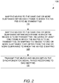
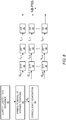
- the radio network node 10 in this regard performs the processing shown in Figure 2 for transmitting the signals 14, 16 within a synchronization signal period 18.
- processing at the radio network node 10 involves mapping the NB-PSS 14 to the same one or more subframes 22 within each frame 20 in which the NB-PSS is to be transmitted (Block 110). That is, the subframe(s) 22 in which the NB-PSS 14 is mapped are the same across the different frames 20 in which the NB-PSS 14 is transmitted (i.e., the positions of the subframes 22 within each frame 20 is the same).
- the radio network node 10 maps the NB-PSS 14 to the same two subframes 22A and 22B within each frame 20 in which the NB-PSS 14 is to be transmitted. The position of these two subframes 22A and 22B is the same within each frame 20 (e.g., the NB-PSS 14 is mapped to subframe positions 4 and 5 within each frame 20 in which the NB-PSS 14 is transmitted).
- Processing at the radio network node 10 similarly involves mapping the NB-SSS 16 to the same one or more subframes 22 within each frame 20 in which the NB-SSS 16 is to be transmitted (Block 110). Again, this means that the subframe(s) 22 in which the NB-SSS 16 is mapped are the same across the different frames 20 in which the NB-SSS 16 is transmitted (i.e., the positions of the subframes 22 within each frame 20 is the same). As shown in Figure 1 , for example, the radio network node 10 maps the NB-SSS 16 to the same single subframe 22C within each frame 20 in which the NB-SSS 16 is to be transmitted.
- the NB-SSS 16 is transmitted within at least one frame 20 in which the NB-PSS 14 is transmitted. That is, the radio network node 10 transmits the NB-PSS 14 and NB-SSS 16 within at least one frame 20 that is the same. The radio network node 10 accomplishes this by mapping the NB-SSS 16 to one or more subframes 22 that differ from the one or more subframes 22 to which the NB-PSS 14 is mapped.
- Figure 1 for instance shows the NB-PSS 14 and NB-SSS 16 both being transmitted within the last frame of a synchronization signal period 18, but the NB-PSS 14 is mapped to subframes 22A and 22B while the NB-SSS 16 is mapped to a different (non-overlapping) subframe 22C within that same frame.
- processing 100 at the radio network node 10 further comprises transmitting the NB-PSS 14 and NB-SSS 16 within the synchronization signal period 18 according to this mapping (Block 130).
- the radio network node 10 transmits the NB-SSS in every other frame in which the NB-PSS is transmitted.
- Transmitting the NB-PSS and NB-SSS in this way advantageously facilitates higher synchronization signal density within the synchronization signal period 18. Indeed, by transmitting the NB-PSS 14 and NB-SSS 16 in different subframes (i.e., with different subframe positions in time), the NB-PSS 14 transmission density is not constrained by potential collision with the NB-SSS 16 transmission (e.g., the NB-PSS 14 and NB-SSS 16 may be transmitted within the same frame, because they are mapped to different subframes).
- Transmitting the NB-PSS 14 with higher density in time translates into synchronization that proves more robust in the face of low SNR (e.g., due to low transmission power for an in-band or guard band transmission of the narrowband synchronization signals 14, 16). Furthermore, the synchronization signal density is increased in this way without meaningful impact on the complexity demanded for synchronization signal detection, e.g., when the synchronization signals are transmitted using the same subframes in every frame.
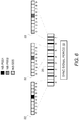
- Figure 3A illustrates one non-limiting example of how NB-PSS 14 density is increased by mapping the synchronization signals 14, 16 according to the processing of Figure 2 .
- a synchronization signal period 18 comprises eight frames 20, consecutively indexed or otherwise numbered as frames 0-7. Each frame 20 in turn comprises ten subframes 22, consecutively indexed or otherwise numbered as subframes 0-9.
- the radio network node 10 maps the NB-PSS 14 to the same two subframes 22 (indexed as subframes 4 and 5) in each frame in which the NB-PSS 14 is to be transmitted. More particularly in this example, the radio network node 10 generates the NB-PSS 14 as two different base sequences NB-PSS1 and NB-PSS2 (e.g., Zadoff-Chu sequences), and maps NB-PSS1 to subframe 4 and maps NB-PSS2 to subframe 5.
- NB-PSS1 and NB-PSS2 e.g., Zadoff-Chu sequences
- the radio network node 10 maps the NB-SSS 16 to only one subframe 22 in each frame 20 in which the NB-SSS 16 is transmitted (although two subframes may be used in other embodiments). Indeed, in at least some embodiments, transmission of the NB-SSS 16 in only one subframe still provides acceptable detection performance for the NB-SSS 16 even in low SNR environments. Regardless, this one subframe is different than any of the subframes to which the NB-PSS 14 is mapped. As shown, the node 10 maps the NB-SSS 16 to subframe 9, which is distinct from subframes 4 and 5 to which the NB-PSS 14 is mapped.
- the radio network node 10 transmits the NB-PSS 14 in every one of the eight frames 0-7 within the synchronization signal period 18.
- the radio network node 10 With lower density transmission of NB-SSS 16 proving sufficient in even the low SNR environments, the radio network node 10 by contrast transmits NB-SSS 16 in only one frame of the synchronization signal period 18; namely, the last frame 7. Where both the NB-PSS 14 and NB-SSS 16 are transmitted in the last frame 7 in this way, collision between the signals 14, 16 is avoided due to the signals 14, 16 occupying different subframes.
- the radio network node 10 still maintains flexibility regarding the density of the NB-PSS 14.
- the radio network node 10 instead transmits the NB-PSS 14 with lower density, by transmitting the NB-PSS 14 in every other frame 20, e.g., in only odd-numbered frames of a synchronization signal period 18 (i.e., 1, 3,5,7,).
- the radio network node 10 maps the NB-PSS 14 and NB-SSS 16 to certain select subframes, based on one or more constraints that govern how different subframes are permitted to be used. These constraints may concern for instance whether any given subframe is configurable as a low interference subframe (e.g., a multicast-broadcast single frequency network, MBSFN, subframe), a downlink subframe, and/or a subframe in which system information may be transmitted on a broadcast channel. Regardless of the particular constraints, though, the radio network node 10 maps the NB-PSS 14 and NB-SSS 16 to certain subframes selected in such a way as to balance potentially competing constraints about how the subframes are to be used.
- MBSFN multicast-broadcast single frequency network
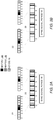
- FIG. 4A illustrates seven such possible TDD configurations.
- subframes 0 and 5 are configured as downlink subframes in all seven possible TDD configurations
- subframe 9 is configured as a downlink subframe in all possible TDD configurations except configuration 0
- subframes 4 and 8 are configured as downlink subframes in four out of three possible TDD configurations.
- the radio network node 10 in some embodiments maps each of the NB-PSS 14 and NB-SSS 16 exclusively to one or more subframes that are downlink subframes in all (or a majority of) possible TDD configurations of the radio network node 10.
- the radio network node 10 in its mapping accounts for the fact that certain subframes may be configurable as so-called low interference subframes.
- a low interference subframe is a subframe that causes no or a limited amount of interference to other subframes transmitted by a different transmitter on the same frequency resource.
- the radio network node 10 may for instance reduce its transmission power, e.g., as compared to a nominal transmission power for normal subframes, on one or more transmission resources within a low interference subframe (e.g., by puncturing or otherwise not transmitting on certain time-frequency resources).
- a low interference subframe may be a multicast-broadcast single frequency network (MBSFN) subframe.
- MBSFN multicast-broadcast single frequency network
- the radio network node 10 in some embodiments maps each of the NB-PSS 14 and NB-SSS 16 exclusively to one or more subframes that are immune to configuration as low interference subframes.
- Figure 4B for instance illustrates one example where subframes 1-3 and 6-8 are configurable as low interference subframes.
- the radio network node 10 selects the subframes to which the NB-PSS 14 and NB-SSS 16 are to be mapped, by accounting for this. Indeed, in some embodiments, the radio network node 10 selects the subframes to which to map the NB-PSS 14 and NB-SSS 16 from the set consisting of subframes 0, 4, 5, and 9, since those subframes are immune to configuration as a low interference subframe.
- the radio network node 10 in its mapping accounts for the fact that system information may be transmitted on a broadcast channel within certain subframes.
- Figure 4C for example illustrates that system information is transmitted on a broadcast channel (e.g., the narrowband physical broadcast channel, NB-PBCH) within subframe 0.
- the radio network node 10 in some embodiments maps each of the NB-PSS 14 and NB-SSS 16 exclusively to subframes that lack transmission of system information on a broadcast channel.
- the radio network node 10 selects the subframes to which to map the NB-PSS 14 and NB-SSS 16 from the set consisting of subframes 1-9, since those subframes (always) lack transmission of system information.
- the radio network node 10 maps each of the NB-PSS 14 and NB-SSS 16 exclusively to one or more subframes that are immune to configuration as low interference subframes and are downlink subframes in all (or a majority of) possible TDD configurations of the radio network node 10.
- the subframes to which the NB-PSS 14 and NB-SSS 16 are mapped namely, subframes 4, 5, and 9 are immune to configuration as low interference subframes according to Figure 4B .
- the subframes are downlink subframes in a majority of the possible TDD configurations in Figure 4A , namely, configurations 1, 2, 4, and 5 (subframe 9 is not a downlink subframe in configuration 0, and subframe 4 is not a downlink subframe in configuration 3 or 6).
- Figures 3A-3B further represent embodiments where the radio network node 10 also maps each of the NB-PSS 14 and NB-SSS 16 exclusively to one or more subframes that lack transmission of system information on a broadcast channel. Indeed, according to Figure 4C , no system information is transmitted on the subframes 4, 5, and 9 to which the NB-PSS 14 and NB-SSS 16 are mapped.
- the radio network node 10 maps the NB-PSS 14 and NB-SSS 16 to subframes that are compatible with a greater number of potential TDD configurations than the mappings in Figures 3A-3B .
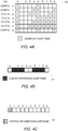
- Figures 5A-5B illustrate different examples in this regard.
- the radio network node 10 maps the NB-PSS 14 to only a single subframe within each frame in which the NB-PSS 14 is to be transmitted. Indeed, rather than mapping the NB-PSS 14 to subframes 4 and 5 as in Figures 3A-3B , the radio network node 10 maps the NB-PSS 14 to only subframe 5.
- the radio network node 10 In order to map the NB-PSS 14 to only a single subframe, the radio network node 10 in some embodiments generates the NB-PSS 14 to comprise a single NB-PSS sequence.
- the radio network node 10 may for instance generate this single sequence from the sum of two base NB-PSS sequences.
- the radio network node 10 may generate the same two base NB-PSS sequences transmitted in different subframes in Figures 3A-3B , namely 1 sequences NB-PSS1 and NB-PSS2, but sum them together, e.g., as 1 2 NB-PSS 1 + NB-PSS 2 in order to form a single combined sequence for transmission in a single subframe.
- the radio network node 10 still transmits the NB-SSS 16 in only one frame of the synchronization signal period 18 (e.g., the last frame), as in Figures 3A-3B , while mapping the NB-PSS 14 as shown in Figures 5A-5B .
- the radio network node 10 transmits the NB-SSS 16 in more than one frame of the synchronization signal period 18.
- the radio network node 10 may transmit the NB-SSS 16 in each frame in which the NB-PSS 14 is transmitted.
- the radio network node 10 may transmit the NB-SSS 16 in fewer frames (e.g., in every other frame in which the NB-PSS 14 is transmitted).
- the radio network node 10 in at least some embodiments advantageously transmits the NB-SSS 16 at a higher density, e.g., than needed for detecting the NB-SSS 16 even in low SNR environments.
- the node 10 may exploit the increase in information-carrying capacity resulting from this higher density, or may otherwise utilize the NB-SSS 16, in order to signal one or more parameters to the wireless communication device 12.
- These one or more parameters may include for instance a narrowband deployment type indicating whether narrowband transmissions from the radio network node 10 are in-band of a wideband transmission, in a guard band of a wideband transmission, or standalone.
- the one or more parameters may include a transmission resource index indicating a location of narrowband transmissions that are located in-band of a wideband transmission (e.g., a physical resource block, PRB, index of a NB-loT transmission with an in-band deployment).
- the one or more parameters additionally or alternatively include an operation mode of the radio network node 10 indicating whether the radio network node 10 is operating in a frequency division duplexing mode or a time division duplexing mode.
- the radio network node 10 may signal these one or more parameters via the NB-SSS 16 in any number of ways. For example, the radio network node 10 may select a sequence on which the NB-SSS 16 is generated, based on the one or more parameters. In this way, the selected sequence and thereby the NB-SSS 16 encodes or implicitly indicates the one or more parameters. In other embodiments explained more fully below, the radio network node 10 implicitly indicates the one or more parameters by the way in which the NB-SSS 16 is transmitted (e.g., which subframes and/or frames in which the NB-SSS 16 is transmitted).
- the radio network node 10 may signal any or all of the above-described parameters via the NB-PSS 14.
- the radio network node 10 in such cases may similarly select a sequence on which the NB-PSS 14 is generated, based on the one or more parameters. In this way, the selected sequence and thereby the NB-PSS 14 encodes or implicitly indicates the one or more parameters.
- the radio network node 10 implicitly indicates the one or more parameters by the way in which the NB-PSS 14 is transmitted (e.g., which subframes and/or frames in which the NB-PSS 14 is transmitted).
- the radio network node 10 maps the NB-PSS 14 and NB-SSS 16 to subframes that are compatible with an even greater number of potential TDD configurations than the mappings in Figures 3A-3B and 5A-5B .
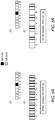
- Figure 6 illustrate one example in this regard.
- the radio network node 10 maps the NB-SSS 16 to only a single subframe. But rather than mapping the NB-SSS 16 to subframe 9, as in Figures 3A-3B and 5A-5B , the radio network node 10 maps the NB-SSS 16 to subframe 0. This means that the mapping is compatible with all of the possible TDD configurations illustrated in Figure 4A . Indeed, the subframes to which the NB-PSS 14 and NB-SSS 16 are mapped (namely, subframes 0 and 5) are designated as downlink subframes in all seven of the TDD configurations. Moreover, these subframes are immune to configuration as low interference subframes according to Figure 4B .
- the radio network node's mapping proves more compatible with possible TDD configurations, but at the expense of potential conflict with system information transmissions.
- system information may be transmitted on a broadcast channel in subframe 0. Mapping the NB-SSS 16 to subframe 0 as in Figure 6 thereby subjects the NB-SSS 16 to conflict with system information transmissions.
- the radio network node 10 in various embodiments resolves this potential conflict by transmitting the NB-SSS 16 in as few frames as needed to achieve a target NB-SSS detection threshold, and transmitting system information in one or more of the other NB-SSS-free frames.
- the radio network node 10 transmits the NB-SSS 16 in only the last frame (i.e., frame 7) of the synchronization signal period 18.
- frame 7 the last frame of the synchronization signal period 18.
- such low density transmission may meet a target NB-SSS detection threshold, even in low SNR environments. And this frees up the remaining frames in the synchronization signal period 18 for system information transmission.
- the system information may be transmitted within subframe 0 of frames 0-6, while NB-SSS 16 is transmitted within subframe 0 of frame 7. Omitting system information from this one frame only marginally degrades detection performance of the system information (e.g., of the NB-PBCH), e.g., by approximately 0.6 dB.
- the system information e.g., of the NB-PBCH
- Figure 6 also shows alternative embodiments for transmitting the NB-PSS 14 within a single subframe. Contrasted with the embodiments illustrated by Figures 5A-5B in which different base NB-PSS sequences are transmitted in combination at the same time, the radio network node 10 in these embodiments transmits different NB-PSS sequences at different times (without combining the sequences). Specifically, the radio network node 10 transmits different respective ones of the base NB-PSS sequences in different frames of the synchronization signal period 18. In some embodiments, only one base NB-PSS sequence is transmitted in any given frame.
- Figure 6 illustrates an example with two base NB-PSS sequences (namely, NB-PSS1 and NB-PSS2), and where the radio network node 10 transmits a base NB-PSS sequence in every frame of the synchronization signal period 18.
- the radio network node 10 alternates every other frame between transmitting NB-PSS1 and transmitting NB-PSS2 (e.g., NB-PSS1 is transmitted in even-numbered frames, while NB-PSS2 is transmitted in odd-numbered frames).
- the radio network node 10 transmits the NB-PSS within select frames of the synchronization signal period
- the node 10 alternates every other one of the select frames between transmitting one of the two base NB-PSS sequences and transmitting the other of the two base NB-PSS sequences.
- this approach advantageously enables the wireless communication device 12 to estimate both the frequency offset and the timing offset simultaneously (or in parallel).
- the radio network node 10 may apply the same embodiment without regard to conditions that may affect signal density demands (e.g., always apply the embodiment in Figure 6 regardless of whether operating in TDD or FDD mode).
- the radio network node 10 may selectively apply different embodiments under different conditions and/or at different times.
- the radio network node 10 applies one embodiment when operating in a TDD mode and applies a different embodiment when operating in a frequency division duplexing (FDD) mode.
- the radio network node 10 may transmit the NB-PSS 14 and NB-SSS 16 according to the embodiment illustrated in Figure 6 when operating in TDD mode (e.g., to ensure compatibility with all possible TDD configurations), but transmit the NB-PSS 14 and NB-SSS 16 according to the embodiment illustrated in Figures 3A-3B or 5A-5B when operating in FDD mode (e.g., since TDD configuration compatibility is inapplicable).
- the node's transmission of the NB-PSS 14 and NB-SSS 16 encodes or implicitly indicates the node's operating mode as being either TDD or FDD.
- the wireless communication device 12 may for instance identify the node's operating mode as being TDD or FDD based on evaluating the time separation between NB-PSS transmissions.
- the radio network node 10 applies one embodiment when operating under conditions demanding relatively high synchronization signal density and applies a different embodiment when operating under conditions demanding only a relatively low synchronization signal density.
- Such conditions may for instance depend on the narrowband deployment mode of the radio network node, which may change dynamically or at a given point in time. For example, a standalone mode may produce conditions that demand a relatively lower synchronization signal density (e.g., a lower repetition interval), whereas in-band or guard band mode may produce conditions that demand a relatively higher synchronization signal density (e.g., a higher repetition interval).
- the radio network node 10 transmits the NB-PSS 14 and NB-SSS 16 according to the embodiments illustrated in Figure 3A , 5A , or 6 when operating in in-band or guard band mode, but transmits the NB-PSS 14 and NB-SSS 16 according to the embodiment illustrated in Figures 3B or 5B when operating in standalone mode.
- the radio network node 10 transmits the NB-PSS 14 and NB-SSS 16 according to the embodiments illustrated in Figure 3B or 5B when operating in in-band or guard band mode, but transmits the NB-PSS 14 and NB-SSS 16 according to another embodiment not shown when operating in standalone mode.
- One such non-shown embodiment may comprise for instance a modified version of Figure 3B or 5B , where the NB-PSS 14 and/or NB-SSS 16 are transmitted in only a subset of the shown frames and/or subframes (e.g., the NB-SSS 16 is transmitted in only frames 1 and 5, rather than 1, 3, 5, and 7).
- the node's transmission of the NB-PSS 14 and NB-SSS 16 in these embodiments encodes or implicitly indicates the node's deployment mode as being either standalone, in-band, or guard band.
- the wireless communication device 12 may for instance identify the node's deployment mode as being standalone, in-band, or guard band based on evaluating the time separation between NB-PSS transmissions.
- FIGS 7A-87D illustrate a few examples in a context where the narrowband synchronization signals 14, 16 are transmitted in-band of a wideband LTE transmission.
- a subframe 22 in this example comprises multiple Orthogonal Frequency Division Multiplexing (OFDM) symbols 24.
- OFDM Orthogonal Frequency Division Multiplexing
- Figures 7A-7B show that a subframe 22 comprises fourteen OFDM symbols 24. This is the case for instance when the synchronization signals 14, 16 are transmitted with a normal length cyclic prefix (CP).
- the NB-PSS 14 may be transmitted within the last eleven of the subframe's OFDM symbols. The remaining OFDM symbols 24 are not used by the synchronization signals 14, 16, but instead are left free for transmission of wideband control information (e.g., the LTE PDCCH).
- Figure 7B shows that the NB-SSS 14 may be transmitted within the last nine of the subframe's OFDM symbols. Again, the remaining OFDM symbols 24 are not used, but instead are left free for other transmissions including wideband control information. Regardless, the NB-PSS 14 and NB-SSS 16 occupy a fixed number of OFDM symbols in each synchronization signal period 18.
- FIGS 7C-7D further show a so-called resource block that comprises multiple resource elements.
- Each resource element is a time-frequency resource formed as a combination of one OFDM symbol and one frequency subcarrier (e.g., of 15kHz).
- the NB-PSS 14 and NB-SSS 16 are punctured on certain resource elements by a wideband cell-specific reference signal (CRS) 26 (e.g., LTE CRS).
- CRS wideband cell-specific reference signal
- the wideband CRS 26 also puncture transmission of wideband control information on a wideband physical downlink control channel (WB-PDCCH) 28, such as the LTE PDCCH.
- WB-PDCCH wideband physical downlink control channel
- the NB-PSS 14 and NB-SSS 16 may occupy a different number of symbols within any given subframe 22.
- the NB-PSS 14 spans 11 or 9 symbols in each subframe 22
- the NB-SSS 16 spans 6 to 11 symbols in each subframe 22.
- Still other embodiments herein support extended cyclic prefixes (CP) that are longer in length than normal CP.
- CP extended cyclic prefixes
- each subframe comprises fourteen OFDM symbols, whereas with extended CP, each subframe comprises only 12 OFDM symbols.
- the NB-PSS 14 spans 9 symbols in each subframe 22, and the NB-SSS 16 spans 6 to 9 symbols in each subframe 22.
- the radio network node 10 realizes support for both normal and extended CP in some embodiments by generating the NB-PSS 14 using base sequences of different lengths. For example, the radio network node 10 may generate the NB-PSS 14 using one or more base sequences of length 141 when transmitting with a normal CP, but may generate the NB-PSS 14 using one or more base sequences of length 133 when transmitting with an extended CP. No matter that length, though, the radio network node 10 may puncture certain symbols in the sequence to achieve a required number of symbols (e.g., 132) for mapping to the 9 OFDM symbols spanned by the NB-PSS 14.
- a required number of symbols e.g. 132
- the radio network node 10 realizes support for both normal and extended CP by using different puncturing patterns for different normal and extended CP. Specifically, the radio network node 10 in some embodiments selects a length of a cyclic prefix with which to transmit the NB-PSS and NB-SSS. The node 10 then generates the NB-PSS 14 in different ways for different selected lengths. The node 10 does so by using the same one or more base NB-PSS sequences, irrespective of the selected CP length, but using different puncturing patterns for different selected CP lengths.
- the radio network node 10 may puncture or remove a certain pattern of symbols from a length-141 base sequence; namely, the 13 th , 26 th , 51 st , 64 th , 77 th , 90 th , 103 rd , 116 th , and 141 st symbols, in order to make the NB-PSS span eleven OFDM symbols.
- the radio network node 10 may puncture or remove another pattern of symbols from the length-141 base sequence; namely, the 13 th , 14 th , 15 th , 28 th , 29 th , 30 th , 43 rd , 44 th 45 th , 58 th 59 th 60 th 73 rd 74 th 75 th , 88 th 89 th , 90 th , 103 rd , 104 th , 105 th , 118 th , 119 th , 120 th , and 133 rd through 141 st symbols, in order to make the NB-PSS span nine OFDM symbols.
- support for extended CP requires increasing the number of NB-PSS correlations by a factor of 2, in order to achieve satisfactory performance.
- the radio network node 10 in some embodiments generates the NB-SSS in the same way for different selected CP lengths.
- Figure 8 illustrates additional details of synchronization signal generation according to one or more embodiments.
- a base NB-PSS sequence with a length of L is obtained by a sequence obtaining module or circuit 30 in the form of a Zadoff Chu sequence.
- a symbol removal module or circuit 32 removes a certain pattern of symbols or elements from the sequence in order to obtain a punctured Zadoff-Chu (ZC) sequence d u .
- ZC Zadoff-Chu
- a subsequence generation module or circuit 34 then divides the punctured ZC sequence d u into m sub-sequences, shown as d u,1 , d u,2 , ... d u,m . If the length of the sequences are not divisible by m, then zeros may be padded to make it divisible.
- a discrete Fourier Transform (DFT) 36 is then employed for each of these m sub-sequences to generate frequency domain representations r u,1 , r u,2 , ... r u,m of the sub-sequences.
- DFT discrete Fourier Transform
- frequency domain representations are input into an inverse fast Fourier transform module or circuit 38, in order to produce rate-converted versions t u,1 , t u,2 , ... t u,m of the sub-sequences; that is the rate-converted versions are at a different sampling rate (e.g., 1.92 kHz) due to the DFT and IFFT.
- a cyclic prefix (CP) module or circuit 40 is finally employed to add and CP and generate the synchronization signal NB-PSS.
- the NB-PSS consists of two Zadoff-Chu (ZC) sequences NB-PSS1 and NB-PSS2.
- ZC Zadoff-Chu
- NB-PSS1 is generated based on a N PSS -length ZC sequence with root index 1
- NB-PSS2 is based on the complex conjugate of NB-PSS1:
- the NB-SSS design may also consist of two Zadoff-Chu (ZC) sequences NB-SSS1 and NB-SSS2, e.g., in embodiments not shown in any of the Figures where NB-SSS is transmitted in two subframes rather than just one.
- ZC Zadoff-Chu
- NB-SSS1 and NB-SSS2 in this case are generated based on a N sss -length ZC sequence with root index u 1 and u 2 respectively.
- N SSS is chosen to be prime (e.g., 107) in order to enable support for upto N SSS - 1 different sequences.
- the combination of the two IDs (u 1 u 2 ) is sufficient to encode the physical cell ID and the timing within the synchronization signal period (e.g., an 80 ms block).
- the NB-SSS may consist of a single ZC sequence generated in a similar manner as NB-SSS1 or NB-SSS2.
- a scrambling code may be applied on it in order to provide the correct timing within a synchronization signal period (e.g, an 80 ms block).
- the radio network node 10 may use a combination of the roots and cyclic shifts of the different Zadoff Chu sequences.
- embodiments herein include corresponding processing performed at the wireless communication device 12 for receiving the NB-PSS 14 and NB-SSS 16, as transmitted by the radio network node 10.
- Figure 9 illustrations processing 200 performed by the wireless communication device 12 in this regard.
- processing 200 at the device 12 includes receiving the NB-PSS 14 and NB-SSS 16 within the synchronization signal period 18 (Block 210). This may include for instance receiving the NB-SSS in every other frame in which the NB-PSS is received. Processing 200 further includes de-mapping the NB-PSS 14 from the same one or more subframes 22 within each frame 20 in which the NB-PSS 14 is received (Block 220). Processing 200 also entails de-mapping the NB-SSS 16 from the same one or more subframes 22 within each frame 20 in which the NB-SSS 16 is receive (Block 230). This includes at least one frame 20 in which the NB-PSS 14 is received.
- the device 12 does this by de-mapping the NB-SSS 16 from one or more subframes 22 that differ from the one or more subframes 22 from which the NB-PSS 14 is de-mapped.
- the device 12 may for instance employ reception processing as needed to recover the NB-PSS 14 and NB-SSS 16 as transmitted according to any of Figures 3-8 .
- the device 12 also acquires frame and symbol timing of a cell provided by the radio network node 10, based on the received NB-PSS 14 and NB-SSS 16.
- the radio network node 10 and wireless communication device 12 operate according to narrowband Internet of Things (NB-IoT) specifications.
- NB-IoT narrowband Internet of Things
- embodiments described herein are explained in the context of operating in or in association with a RAN that communicates over radio communication channels with wireless communication devices, also interchangeably referred to as wireless terminals or UEs, using a particular radio access technology. More specifically, embodiments are described in the context of the development of specifications for NB-IoT, particularly as it relates to the development of specifications for NB-loT operation in spectrum and/or using equipment currently used by E-UTRAN, sometimes referred to as the Evolved UMTS Terrestrial Radio Access Network and widely known as the LTE system.
- a radio network node 10 herein is any type of network node (e.g., a base station) capable of communicating with another node over radio signals.
- a wireless communication device 12 is any type device capable of communicating with a radio network node 10 over radio signals.
- a wireless communication device 12 may therefore refer to a machine-to-machine (M2M) device, a machine-type communications (MTC) device, a NB-loT device, etc..
- M2M machine-to-machine
- MTC machine-type communications
- NB-loT device a NB-loT device, etc.
- the wireless device may also be a UE, however it should be noted that the UE does not necessarily have a "user" in the sense of an individual person owning and/or operating the device.
- a wireless device may also be referred to as a radio device, a radio communication device, a wireless terminal, or simply a terminal - unless the context indicates otherwise, the use of any of these terms is intended to include device-to-device UEs or devices, machine-type devices or devices capable of machine-to-machine communication, sensors equipped with a wireless device, wireless-enabled table computers, mobile terminals, smart phones, laptop-embedded equipped (LEE), laptop-mounted equipment (LME), USB dongles, wireless customer-premises equipment (CPE), etc.
- LOE laptop-embedded equipped
- LME laptop-mounted equipment
- CPE wireless customer-premises equipment
- M2M machine-to-machine
- MTC machine-type communication
- wireless sensor and sensor may also be used. It should be understood that these devices may be UEs, but are generally configured to transmit and/or receive data without direct human interaction.
- a wireless communication device as described herein may be, or may be comprised in, a machine or device that performs monitoring or measurements, and transmits the results of such monitoring measurements to another device or a network.
- machines are power meters, industrial machinery, or home or personal appliances, e.g. refrigerators, televisions, personal wearables such as watches etc.
- a wireless communication device as described herein may be comprised in a vehicle and may perform monitoring and/or reporting of the vehicle's operational status or other functions associated with the vehicle.
- the radio network node 10 as described above may perform the processing herein by implementing any functional means or units.
- the radio network node 10 comprises respective circuits configured to perform the steps shown in Figure 2 .
- the circuits in this regard may comprise circuits dedicated to performing certain functional processing and/or one or more microprocessors in conjunction with memory.
- memory which may comprise one or several types of memory such as read-only memory (ROM), random-access memory, cache memory, flash memory devices, optical storage devices, etc.
- the memory stores program code that, when executed by the one or more microprocessors, carries out the techniques described herein. That is, in some embodiments memory of the radio network node 10 contains instructions executable by the processing circuitry whereby the radio network node 10 is configured to carry out the processing herein.
- FIG 10 illustrates additional details of a radio network node 10 in accordance with one or more embodiments.
- the radio network node 10 includes one or more processing circuits 620 and one or more radio circuits 610.
- the one or more radio circuits 610 are configured to transmit via one or more antennas 640.
- the one or more processing circuits 620 are configured to perform processing described above, e.g., in Figure 2 , such as by executing instructions stored in memory 630.
- the one or more processing circuits 620 in this regard may implement certain functional means or units.
- FIG 11 in this regard illustrates a radio network node 10 in accordance with one or more other embodiments.
- the radio network node 10 may include a mapping module or unit 650 for mapping the NB-PSS 14 and NB-SSS 16 as described above, and a transmitting module or unit 660 for transmitting the NB-PSS 14 and NB-SSS 16, e.g., via the one or more radio circuits 610.
- These modules or units may be implemented by the processing circuit(s) 620 of Figure 10 .
- the wireless communication device 12 may perform the processing herein by implementing any functional means or units.
- the wireless communication device 12 comprises respective circuits configured to perform the steps shown in Figure 9 .
- the circuits in this regard may comprise circuits dedicated to performing certain functional processing and/or one or more microprocessors in conjunction with memory.
- memory which may comprise one or several types of memory such as read-only memory (ROM), random-access memory, cache memory, flash memory devices, optical storage devices, etc.
- the memory stores program code that, when executed by the one or more microprocessors, carries out the techniques described herein. That is, in some embodiments memory of the device 12 contains instructions executable by the processing circuitry whereby the device 12 is configured to carry out the processing herein.
- Figure 12 illustrates additional details of a wireless communication device 12 in accordance with one or more embodiments.
- the wireless communication device 12 includes one or more processing circuits 720 and one or more radio circuits 710.
- the one or more radio circuits 710 are configured to transmit via one or more antennas 740.
- the one or more processing circuits 720 are configured to perform processing described above, e.g., in Figure 9 , such as by executing instructions stored in memory 730.
- the one or more processing circuits 720 in this regard may implement certain functional means or units.
- Figure 13 in this regard illustrates additional details of a wireless communication device 12 in accordance with one or more other embodiments.
- the device 12 may include a receiving module or unit 750 for receiving the NB-PSS 14 and NB-SSS 16, e.g., via the one or more radio circuits 710, and a de-mapping module or unit 760 for de-mapping the NB-PSS 14 and NB-SSS 16 as described above.
- These units or modules may be implemented by the one or more processing circuits 720 in Figure 12 .
- a computer program comprises instructions which, when executed on at least one processor of a node, cause the node to carry out any of the respective processing described above.
- a computer program in this regard may comprise one or more code modules corresponding to the means or units described above.
- Embodiments further include a carrier containing such a computer program.
- This carrier may comprise one of an electronic signal, optical signal, radio signal, or computer readable storage medium.
Landscapes
- Engineering & Computer Science (AREA)
- Signal Processing (AREA)
- Computer Networks & Wireless Communication (AREA)
- Databases & Information Systems (AREA)
- Mobile Radio Communication Systems (AREA)
- Synchronisation In Digital Transmission Systems (AREA)
- Time-Division Multiplex Systems (AREA)
Description
- The present application generally relates to transmission and reception of synchronization signals, and particular relates to transmission and reception of a narrowband primary synchronization signal and a narrowband secondary synchronization signal within a synchronization signal period.
- A wireless communication device performs a procedure known as cell search in order to find and synchronize to one of the cells in a cellular communication system. Synchronizing to a cell involves synchronizing the device's transmission and reception timing to the cell's transmission and reception timing. For example, transmissions may be performed according to a timing structure that is specified at a relatively high level of granularity in terms of "frames" (e.g., 10ms), at a lower level of granularity in terms of "sub-frames" (e.g., 1 ms), and at yet a lower level of granularity in terms of "symbols". Synchronization in this case therefore includes acquiring the frame and symbol timing of a cell (i.e., acquiring symbol-level timing alignment with the frame structure of a cell). Synchronization may also include acquiring frequency synchronization to the cell (e.g., correcting for frequency offset), obtaining an identifier of the cell, and acquiring an absolute frame number reference.
- Cell search is typically achieved by periodically transmitting one or more known sequences to facilitate detection. The one or more known sequences are referred to collectively as a "synchronization signal". In some systems, a synchronization signal includes multiple different component signals that serve different purposes in synchronization. These component signals include a primary synchronization signal (PSS) and a secondary synchronization signal (SSS) in some systems, such as Wideband Code Division Multiplexing (WCDMA) and Long Term Evolution (LTE) systems. The PSS alone may for instance facilitate timing synchronization at a coarse resolution (e.g., on a symbol basis), whereas the PSS in combination with the SSS facilitates timing synchronization at a finer resolution (e.g., on a frame basis).
- Synchronization proves challenging in certain contexts. In particular, cellular communication systems are currently being developed and improved for machine type communication (MTC). MTC is characterized by lower demands on data rates than for example mobile broadband, but with higher requirements on e.g. low cost device design, better coverage, and ability to operate for years on batteries without charging or replacing the batteries. Currently, the 3rd generation partnership project (3GPP) is standardizing a feature called Narrowband Internet of Things (NB-loT) for satisfying all the requirements put forward by MTC type applications, while maintaining backward compatibility with the current LTE radio access technology. NB-loT transmissions may occur in-band of a wideband LTE transmission, within a guard band of a wideband LTE transmission, or in standalone spectrum. Regardless, synchronization in a NB-loT environment proves challenging because NB-loT devices may need to operate at very low signal to noise ratios (SNRs). This means that narrowband synchronization signal design should be extremely robust to be able to operate at a wide range of SNRs, yet still provide backwards compatibility. Known narrowband synchronization signal designs fall short in this regard. Huawei et al. "NB-IOT - downlink physical layer concept description" R1-156462 3GPP draft, and Ericsson et al. "NB-LTE - general concept description" R1-156010 relate to the narrowband concept.
- The invention is defined by the appended claims. A method for transmitting is provided according to
claim 1. A method for receiving is provided according toclaim 6. A radio network node is provided according to claim 11. A wireless communication device is provided according toclaim 13. Further embodiments are defined by the dependent claims. -
-
Figure 1 is a block diagram of a wireless communication system according to one or more embodiments. -
Figure 2 is a logic flow diagram of a method implemented by a radio network node according to one or more embodiments. -
Figures 3A-3B are block diagrams of different synchronization signal mappings according to one or more embodiments. -
Figures 4A-4C are block diagrams of different subframe constraints taken into account in the synchronization signal mappings according to one or more embodiments. -
Figures 5A-5B are block diagrams of different synchronization signal mappings according to one or more embodiments. -
Figure 6 is a block diagram of a synchronization signal mapping according to one or more embodiments. -
Figures 7A-7D are block diagrams of different synchronization signal mappings according to one or more embodiments. -
Figure 8 is a block diagram of synchronization signal generation according to one or more embodiments. -
Figure 9 is a logic flow diagram of a method implemented by a wireless communication device according to one or more embodiments. -
Figure 10 is a block diagram of a radio network node according to one or more embodiments. -
Figure 11 is a block diagram of a radio network node according to one or more other embodiments. -
Figure 12 is a block diagram of a wireless communication device according to one or more embodiments. -
Figure 13 is a block diagram of a wireless communication device according to one or more other embodiments. -
Figure 1 illustrates aradio network node 10 and awireless communication device 12 in a wireless communication system according to one or more embodiments. Theradio network node 10 is configured to transmit a narrowband primary synchronization signal (NB-PSS) 14 and a narrowband secondary synchronization signal (NB-SSS) 16, e.g., for narrowband Internet of Things (loT). Depending on the node's deployment mode, thesenarrowband signals wireless communication device 12 in some embodiments receives thenarrowband synchronization signals radio network node 10. - The
radio network node 10 transmits the NB-PSS and NB-SSS within asynchronization signal period 18.Figure 1 shows multiplesuch periods 18 asperiods synchronization signal period 18 comprises multiple so-calledframes 20. Aframe 20 is defined as being a specific amount of time (e.g., 10ms) at a certain level of granularity according to the wireless communication system's timing structure. Eachframe 20 comprisesmultiple subframes 22. Eachsubframe 22 is similarly defined as being a specific amount of time (e.g., 1ms) at a lower level of granularity according to the system's timing structure. - The
radio network node 10 transmits the NB-PSS 14 and NB-SSS 16 withincertain frames 20 andsubframes 22, e.g., in order to achieve a certain synchronization signal density within asynchronization signal period 18. Theradio network node 10 in this regard performs the processing shown inFigure 2 for transmitting thesignals synchronization signal period 18. - As shown in
Figure 2 , processing at theradio network node 10 involves mapping the NB-PSS 14 to the same one ormore subframes 22 within eachframe 20 in which the NB-PSS is to be transmitted (Block 110). That is, the subframe(s) 22 in which the NB-PSS 14 is mapped are the same across thedifferent frames 20 in which the NB-PSS 14 is transmitted (i.e., the positions of thesubframes 22 within eachframe 20 is the same). As shown inFigure 1 , for example, theradio network node 10 maps the NB-PSS 14 to the same twosubframes frame 20 in which the NB-PSS 14 is to be transmitted. The position of these twosubframes PSS 14 is mapped tosubframe positions frame 20 in which the NB-PSS 14 is transmitted). - Processing at the
radio network node 10 similarly involves mapping the NB-SSS 16 to the same one ormore subframes 22 within eachframe 20 in which the NB-SSS 16 is to be transmitted (Block 110). Again, this means that the subframe(s) 22 in which the NB-SSS 16 is mapped are the same across thedifferent frames 20 in which the NB-SSS 16 is transmitted (i.e., the positions of thesubframes 22 within eachframe 20 is the same). As shown inFigure 1 , for example, theradio network node 10 maps the NB-SSS 16 to the samesingle subframe 22C within eachframe 20 in which the NB-SSS 16 is to be transmitted. - Notably, the NB-SSS 16 is transmitted within at least one
frame 20 in which the NB-PSS 14 is transmitted. That is, theradio network node 10 transmits the NB-PSS 14 and NB-SSS 16 within at least oneframe 20 that is the same. Theradio network node 10 accomplishes this by mapping the NB-SSS 16 to one ormore subframes 22 that differ from the one ormore subframes 22 to which the NB-PSS 14 is mapped.Figure 1 for instance shows the NB-PSS 14 and NB-SSS 16 both being transmitted within the last frame of asynchronization signal period 18, but the NB-PSS 14 is mapped tosubframes SSS 16 is mapped to a different (non-overlapping)subframe 22C within that same frame. Regardless, processing 100 at theradio network node 10 further comprises transmitting the NB-PSS 14 and NB-SSS 16 within thesynchronization signal period 18 according to this mapping (Block 130). In some embodiments, for instance, theradio network node 10 transmits the NB-SSS in every other frame in which the NB-PSS is transmitted. - Transmitting the NB-PSS and NB-SSS in this way advantageously facilitates higher synchronization signal density within the
synchronization signal period 18. Indeed, by transmitting the NB-PSS 14 and NB-SSS 16 in different subframes (i.e., with different subframe positions in time), the NB-PSS 14 transmission density is not constrained by potential collision with the NB-SSS 16 transmission (e.g., the NB-PSS 14 and NB-SSS 16 may be transmitted within the same frame, because they are mapped to different subframes). Transmitting the NB-PSS 14 with higher density in time translates into synchronization that proves more robust in the face of low SNR (e.g., due to low transmission power for an in-band or guard band transmission of the narrowband synchronization signals 14, 16). Furthermore, the synchronization signal density is increased in this way without meaningful impact on the complexity demanded for synchronization signal detection, e.g., when the synchronization signals are transmitted using the same subframes in every frame. -
Figure 3A illustrates one non-limiting example of how NB-PSS 14 density is increased by mapping the synchronization signals 14, 16 according to the processing ofFigure 2 . - As shown in
Figure 3A , asynchronization signal period 18 comprises eightframes 20, consecutively indexed or otherwise numbered as frames 0-7. Eachframe 20 in turn comprises tensubframes 22, consecutively indexed or otherwise numbered as subframes 0-9. Theradio network node 10 maps the NB-PSS 14 to the same two subframes 22 (indexed assubframes 4 and 5) in each frame in which the NB-PSS 14 is to be transmitted. More particularly in this example, theradio network node 10 generates the NB-PSS 14 as two different base sequences NB-PSS1 and NB-PSS2 (e.g., Zadoff-Chu sequences), and maps NB-PSS1 tosubframe 4 and maps NB-PSS2 tosubframe 5. By contrast, theradio network node 10 maps the NB-SSS 16 to only onesubframe 22 in eachframe 20 in which the NB-SSS 16 is transmitted (although two subframes may be used in other embodiments). Indeed, in at least some embodiments, transmission of the NB-SSS 16 in only one subframe still provides acceptable detection performance for the NB-SSS 16 even in low SNR environments. Regardless, this one subframe is different than any of the subframes to which the NB-PSS 14 is mapped. As shown, thenode 10 maps the NB-SSS 16 tosubframe 9, which is distinct fromsubframes PSS 14 is mapped. - Mapping the NB-
PSS 14 and NB-SSS 16 to different subframes (i.e., at different positions) in this way enables theradio network node 10 to transmit the NB-PSS 14 with higher density in thesynchronization signal period 18, e.g., than would otherwise be possible without this mapping strategy. In fact, in the example ofFigure 3A , theradio network node 10 transmits the NB-PSS 14 in every one of the eight frames 0-7 within thesynchronization signal period 18. With lower density transmission of NB-SSS 16 proving sufficient in even the low SNR environments, theradio network node 10 by contrast transmits NB-SSS 16 in only one frame of thesynchronization signal period 18; namely, thelast frame 7. Where both the NB-PSS 14 and NB-SSS 16 are transmitted in thelast frame 7 in this way, collision between thesignals signals - Moreover, the
radio network node 10 still maintains flexibility regarding the density of the NB-PSS 14. In some embodiments, such as those shown inFigure 3B , theradio network node 10 instead transmits the NB-PSS 14 with lower density, by transmitting the NB-PSS 14 in everyother frame 20, e.g., in only odd-numbered frames of a synchronization signal period 18 (i.e., 1, 3,5,7,...). - In at least some embodiments, the
radio network node 10 maps the NB-PSS 14 and NB-SSS 16 to certain select subframes, based on one or more constraints that govern how different subframes are permitted to be used. These constraints may concern for instance whether any given subframe is configurable as a low interference subframe (e.g., a multicast-broadcast single frequency network, MBSFN, subframe), a downlink subframe, and/or a subframe in which system information may be transmitted on a broadcast channel. Regardless of the particular constraints, though, theradio network node 10 maps the NB-PSS 14 and NB-SSS 16 to certain subframes selected in such a way as to balance potentially competing constraints about how the subframes are to be used. - Consider for instance embodiments where a defined number of possible time division duplex (TDD) configurations govern which subframes are configurable as downlink subframes.
Figure 4A illustrates seven such possible TDD configurations. As shown,subframes subframe 9 is configured as a downlink subframe in all possible TDD configurations exceptconfiguration 0, andsubframes radio network node 10 in some embodiments maps each of the NB-PSS 14 and NB-SSS 16 exclusively to one or more subframes that are downlink subframes in all (or a majority of) possible TDD configurations of theradio network node 10. - Alternatively or additionally, the
radio network node 10 in its mapping accounts for the fact that certain subframes may be configurable as so-called low interference subframes. A low interference subframe is a subframe that causes no or a limited amount of interference to other subframes transmitted by a different transmitter on the same frequency resource. Theradio network node 10 may for instance reduce its transmission power, e.g., as compared to a nominal transmission power for normal subframes, on one or more transmission resources within a low interference subframe (e.g., by puncturing or otherwise not transmitting on certain time-frequency resources). As one example, a low interference subframe may be a multicast-broadcast single frequency network (MBSFN) subframe. - In any event, the
radio network node 10 in some embodiments maps each of the NB-PSS 14 and NB-SSS 16 exclusively to one or more subframes that are immune to configuration as low interference subframes.Figure 4B for instance illustrates one example where subframes 1-3 and 6-8 are configurable as low interference subframes. Theradio network node 10 selects the subframes to which the NB-PSS 14 and NB-SSS 16 are to be mapped, by accounting for this. Indeed, in some embodiments, theradio network node 10 selects the subframes to which to map the NB-PSS 14 and NB-SSS 16 from the set consisting ofsubframes - In still other embodiments, the
radio network node 10 in its mapping accounts for the fact that system information may be transmitted on a broadcast channel within certain subframes.Figure 4C for example illustrates that system information is transmitted on a broadcast channel (e.g., the narrowband physical broadcast channel, NB-PBCH) withinsubframe 0. In order to avoid a conflict with this system information transmission, theradio network node 10 in some embodiments maps each of the NB-PSS 14 and NB-SSS 16 exclusively to subframes that lack transmission of system information on a broadcast channel. InFigure 4C , for example, theradio network node 10 selects the subframes to which to map the NB-PSS 14 and NB-SSS 16 from the set consisting of subframes 1-9, since those subframes (always) lack transmission of system information. - In some embodiments, the
radio network node 10 maps each of the NB-PSS 14 and NB-SSS 16 exclusively to one or more subframes that are immune to configuration as low interference subframes and are downlink subframes in all (or a majority of) possible TDD configurations of theradio network node 10. Consider for instance the embodiments already illustrated inFigures 3A-3B . There, the subframes to which the NB-PSS 14 and NB-SSS 16 are mapped (namely,subframes Figure 4B . Moreover, the subframes are downlink subframes in a majority of the possible TDD configurations inFigure 4A , namely,configurations subframe 9 is not a downlink subframe inconfiguration 0, andsubframe 4 is not a downlink subframe inconfiguration 3 or 6).Figures 3A-3B further represent embodiments where theradio network node 10 also maps each of the NB-PSS 14 and NB-SSS 16 exclusively to one or more subframes that lack transmission of system information on a broadcast channel. Indeed, according toFigure 4C , no system information is transmitted on thesubframes PSS 14 and NB-SSS 16 are mapped. - In other embodiments herein, the
radio network node 10 maps the NB-PSS 14 and NB-SSS 16 to subframes that are compatible with a greater number of potential TDD configurations than the mappings inFigures 3A-3B .Figures 5A-5B illustrate different examples in this regard. - As shown in
Figure 5A-5B , theradio network node 10 maps the NB-PSS 14 to only a single subframe within each frame in which the NB-PSS 14 is to be transmitted. Indeed, rather than mapping the NB-PSS 14 tosubframes Figures 3A-3B , theradio network node 10 maps the NB-PSS 14 toonly subframe 5. In some embodiments, this advantageously means that the subframes to which the NB-PSS 14 and NB-SSS 16 are mapped (namely,subframes 5 and 9) are immune to configuration as low interference subframes according toFigure 4B , are downlink subframes in a majority of the possible TDD configurations inFigure 4A (namely, configurations 1-6, wheresubframe 9 is not a downlink subframe in configuration 0), and lack transmission of system information on a broadcast channel according toFigure 4C . - In order to map the NB-
PSS 14 to only a single subframe, theradio network node 10 in some embodiments generates the NB-PSS 14 to comprise a single NB-PSS sequence. Theradio network node 10 may for instance generate this single sequence from the sum of two base NB-PSS sequences. For example, theradio network node 10 may generate the same two base NB-PSS sequences transmitted in different subframes inFigures 3A-3B , namely 1 sequences NB-PSS1 and NB-PSS2, but sum them together, e.g., as
- In some embodiments (not shown), the
radio network node 10 still transmits the NB-SSS 16 in only one frame of the synchronization signal period 18 (e.g., the last frame), as inFigures 3A-3B , while mapping the NB-PSS 14 as shown inFigures 5A-5B . In other embodiments, though, theradio network node 10 transmits the NB-SSS 16 in more than one frame of thesynchronization signal period 18. For example, as shown inFigures 5A-5B , theradio network node 10 may transmit the NB-SSS 16 in each frame in which the NB-PSS 14 is transmitted. Of course, in other embodiments, theradio network node 10 may transmit the NB-SSS 16 in fewer frames (e.g., in every other frame in which the NB-PSS 14 is transmitted). - Regardless, the
radio network node 10 in at least some embodiments advantageously transmits the NB-SSS 16 at a higher density, e.g., than needed for detecting the NB-SSS 16 even in low SNR environments. Thenode 10 may exploit the increase in information-carrying capacity resulting from this higher density, or may otherwise utilize the NB-SSS 16, in order to signal one or more parameters to thewireless communication device 12. These one or more parameters may include for instance a narrowband deployment type indicating whether narrowband transmissions from theradio network node 10 are in-band of a wideband transmission, in a guard band of a wideband transmission, or standalone. Alternatively or additionally, the one or more parameters may include a transmission resource index indicating a location of narrowband transmissions that are located in-band of a wideband transmission (e.g., a physical resource block, PRB, index of a NB-loT transmission with an in-band deployment). In still other embodiments, the one or more parameters additionally or alternatively include an operation mode of theradio network node 10 indicating whether theradio network node 10 is operating in a frequency division duplexing mode or a time division duplexing mode. - The
radio network node 10 may signal these one or more parameters via the NB-SSS 16 in any number of ways. For example, theradio network node 10 may select a sequence on which the NB-SSS 16 is generated, based on the one or more parameters. In this way, the selected sequence and thereby the NB-SSS 16 encodes or implicitly indicates the one or more parameters. In other embodiments explained more fully below, theradio network node 10 implicitly indicates the one or more parameters by the way in which the NB-SSS 16 is transmitted (e.g., which subframes and/or frames in which the NB-SSS 16 is transmitted). - Alternatively or additionally, the
radio network node 10 may signal any or all of the above-described parameters via the NB-PSS 14. Theradio network node 10 in such cases may similarly select a sequence on which the NB-PSS 14 is generated, based on the one or more parameters. In this way, the selected sequence and thereby the NB-PSS 14 encodes or implicitly indicates the one or more parameters. In other embodiments, theradio network node 10 implicitly indicates the one or more parameters by the way in which the NB-PSS 14 is transmitted (e.g., which subframes and/or frames in which the NB-PSS 14 is transmitted). - In yet other embodiments herein, the
radio network node 10 maps the NB-PSS 14 and NB-SSS 16 to subframes that are compatible with an even greater number of potential TDD configurations than the mappings inFigures 3A-3B and5A-5B .Figure 6 illustrate one example in this regard. - As shown in
Figure 6 , theradio network node 10 maps the NB-SSS 16 to only a single subframe. But rather than mapping the NB-SSS 16 tosubframe 9, as inFigures 3A-3B and5A-5B , theradio network node 10 maps the NB-SSS 16 tosubframe 0. This means that the mapping is compatible with all of the possible TDD configurations illustrated inFigure 4A . Indeed, the subframes to which the NB-PSS 14 and NB-SSS 16 are mapped (namely,subframes 0 and 5) are designated as downlink subframes in all seven of the TDD configurations. Moreover, these subframes are immune to configuration as low interference subframes according toFigure 4B . - In some embodiments, the radio network node's mapping proves more compatible with possible TDD configurations, but at the expense of potential conflict with system information transmissions. As shown in
Figure 4C , for example, system information may be transmitted on a broadcast channel insubframe 0. Mapping the NB-SSS 16 tosubframe 0 as inFigure 6 thereby subjects the NB-SSS 16 to conflict with system information transmissions. - The
radio network node 10 in various embodiments resolves this potential conflict by transmitting the NB-SSS 16 in as few frames as needed to achieve a target NB-SSS detection threshold, and transmitting system information in one or more of the other NB-SSS-free frames. As shown inFigure 6 , for example, theradio network node 10 transmits the NB-SSS 16 in only the last frame (i.e., frame 7) of thesynchronization signal period 18. As described above, such low density transmission may meet a target NB-SSS detection threshold, even in low SNR environments. And this frees up the remaining frames in thesynchronization signal period 18 for system information transmission. For example, the system information may be transmitted withinsubframe 0 of frames 0-6, while NB-SSS 16 is transmitted withinsubframe 0 offrame 7. Omitting system information from this one frame only marginally degrades detection performance of the system information (e.g., of the NB-PBCH), e.g., by approximately 0.6 dB. - Note that
Figure 6 also shows alternative embodiments for transmitting the NB-PSS 14 within a single subframe. Contrasted with the embodiments illustrated byFigures 5A-5B in which different base NB-PSS sequences are transmitted in combination at the same time, theradio network node 10 in these embodiments transmits different NB-PSS sequences at different times (without combining the sequences). Specifically, theradio network node 10 transmits different respective ones of the base NB-PSS sequences in different frames of thesynchronization signal period 18. In some embodiments, only one base NB-PSS sequence is transmitted in any given frame. -
Figure 6 illustrates an example with two base NB-PSS sequences (namely, NB-PSS1 and NB-PSS2), and where theradio network node 10 transmits a base NB-PSS sequence in every frame of thesynchronization signal period 18. In this case, theradio network node 10 alternates every other frame between transmitting NB-PSS1 and transmitting NB-PSS2 (e.g., NB-PSS1 is transmitted in even-numbered frames, while NB-PSS2 is transmitted in odd-numbered frames). More generally, though, where theradio network node 10 transmits the NB-PSS within select frames of the synchronization signal period, thenode 10 alternates every other one of the select frames between transmitting one of the two base NB-PSS sequences and transmitting the other of the two base NB-PSS sequences. In at least some embodiments, this approach advantageously enables thewireless communication device 12 to estimate both the frequency offset and the timing offset simultaneously (or in parallel). - Any of the above embodiments may be used separately or in combination. As an example of an isolated embodiment, the
radio network node 10 may apply the same embodiment without regard to conditions that may affect signal density demands (e.g., always apply the embodiment inFigure 6 regardless of whether operating in TDD or FDD mode). As an example of combined embodiments, by contrast, theradio network node 10 may selectively apply different embodiments under different conditions and/or at different times. - In one or more such embodiments, the
radio network node 10 applies one embodiment when operating in a TDD mode and applies a different embodiment when operating in a frequency division duplexing (FDD) mode. For example, theradio network node 10 may transmit the NB-PSS 14 and NB-SSS 16 according to the embodiment illustrated inFigure 6 when operating in TDD mode (e.g., to ensure compatibility with all possible TDD configurations), but transmit the NB-PSS 14 and NB-SSS 16 according to the embodiment illustrated inFigures 3A-3B or5A-5B when operating in FDD mode (e.g., since TDD configuration compatibility is inapplicable). In such a case, the node's transmission of the NB-PSS 14 and NB-SSS 16 encodes or implicitly indicates the node's operating mode as being either TDD or FDD. Thewireless communication device 12 may for instance identify the node's operating mode as being TDD or FDD based on evaluating the time separation between NB-PSS transmissions. - Alternatively or additionally, the
radio network node 10 applies one embodiment when operating under conditions demanding relatively high synchronization signal density and applies a different embodiment when operating under conditions demanding only a relatively low synchronization signal density. Such conditions may for instance depend on the narrowband deployment mode of the radio network node, which may change dynamically or at a given point in time. For example, a standalone mode may produce conditions that demand a relatively lower synchronization signal density (e.g., a lower repetition interval), whereas in-band or guard band mode may produce conditions that demand a relatively higher synchronization signal density (e.g., a higher repetition interval). - In some embodiments, therefore, the
radio network node 10 transmits the NB-PSS 14 and NB-SSS 16 according to the embodiments illustrated inFigure 3A ,5A , or6 when operating in in-band or guard band mode, but transmits the NB-PSS 14 and NB-SSS 16 according to the embodiment illustrated inFigures 3B or5B when operating in standalone mode. Alternatively, theradio network node 10 transmits the NB-PSS 14 and NB-SSS 16 according to the embodiments illustrated inFigure 3B or5B when operating in in-band or guard band mode, but transmits the NB-PSS 14 and NB-SSS 16 according to another embodiment not shown when operating in standalone mode. One such non-shown embodiment may comprise for instance a modified version ofFigure 3B or5B , where the NB-PSS 14 and/or NB-SSS 16 are transmitted in only a subset of the shown frames and/or subframes (e.g., the NB-SSS 16 is transmitted in only frames 1 and 5, rather than 1, 3, 5, and 7). - Accordingly, the node's transmission of the NB-
PSS 14 and NB-SSS 16 in these embodiments encodes or implicitly indicates the node's deployment mode as being either standalone, in-band, or guard band. Thewireless communication device 12 may for instance identify the node's deployment mode as being standalone, in-band, or guard band based on evaluating the time separation between NB-PSS transmissions. - Those skilled in the art will appreciate that the NB-
PSS 14 and NB-SSS 16 may be mapped more particularly to transmission resources within a given subframe in any of a number of ways.Figures 7A-87D illustrate a few examples in a context where the narrowband synchronization signals 14, 16 are transmitted in-band of a wideband LTE transmission. Asubframe 22 in this example comprises multiple Orthogonal Frequency Division Multiplexing (OFDM)symbols 24. -
Figures 7A-7B show that asubframe 22 comprises fourteenOFDM symbols 24. This is the case for instance when the synchronization signals 14, 16 are transmitted with a normal length cyclic prefix (CP). As shown inFigure 7A , the NB-PSS 14 may be transmitted within the last eleven of the subframe's OFDM symbols. The remainingOFDM symbols 24 are not used by the synchronization signals 14, 16, but instead are left free for transmission of wideband control information (e.g., the LTE PDCCH).Figure 7B shows that the NB-SSS 14 may be transmitted within the last nine of the subframe's OFDM symbols. Again, the remainingOFDM symbols 24 are not used, but instead are left free for other transmissions including wideband control information. Regardless, the NB-PSS 14 and NB-SSS 16 occupy a fixed number of OFDM symbols in eachsynchronization signal period 18. -
Figures 7C-7D further show a so-called resource block that comprises multiple resource elements. Each resource element is a time-frequency resource formed as a combination of one OFDM symbol and one frequency subcarrier (e.g., of 15kHz). As shown, the NB-PSS 14 and NB-SSS 16 are punctured on certain resource elements by a wideband cell-specific reference signal (CRS) 26 (e.g., LTE CRS). Thewideband CRS 26 also puncture transmission of wideband control information on a wideband physical downlink control channel (WB-PDCCH) 28, such as the LTE PDCCH. Transmitting the NB-PSS 14 and NB-SSS 16 in this way, to avoid conflict with CRS and PDCCH transmission, advantageously provides backwards compatibility with associated wideband transmissions (e.g., wideband LTE). - In other embodiments not shown, though, the NB-
PSS 14 and NB-SSS 16 may occupy a different number of symbols within any givensubframe 22. In some normal cyclic prefix embodiments, for example, the NB-PSS 14 spans 11 or 9 symbols in eachsubframe 22, and the NB-SSS 16spans 6 to 11 symbols in eachsubframe 22. - Still other embodiments herein support extended cyclic prefixes (CP) that are longer in length than normal CP. With normal CP, each subframe comprises fourteen OFDM symbols, whereas with extended CP, each subframe comprises only 12 OFDM symbols. In some extended cyclic prefix embodiments, the NB-
PSS 14spans 9 symbols in eachsubframe 22, and the NB-SSS 16spans 6 to 9 symbols in eachsubframe 22. - The
radio network node 10 realizes support for both normal and extended CP in some embodiments by generating the NB-PSS 14 using base sequences of different lengths. For example, theradio network node 10 may generate the NB-PSS 14 using one or more base sequences of length 141 when transmitting with a normal CP, but may generate the NB-PSS 14 using one or more base sequences of length 133 when transmitting with an extended CP. No matter that length, though, theradio network node 10 may puncture certain symbols in the sequence to achieve a required number of symbols (e.g., 132) for mapping to the 9 OFDM symbols spanned by the NB-PSS 14. - In other embodiments, the
radio network node 10 realizes support for both normal and extended CP by using different puncturing patterns for different normal and extended CP. Specifically, theradio network node 10 in some embodiments selects a length of a cyclic prefix with which to transmit the NB-PSS and NB-SSS. Thenode 10 then generates the NB-PSS 14 in different ways for different selected lengths. Thenode 10 does so by using the same one or more base NB-PSS sequences, irrespective of the selected CP length, but using different puncturing patterns for different selected CP lengths. For example, to generate the NB-PSS for normal CP, theradio network node 10 may puncture or remove a certain pattern of symbols from a length-141 base sequence; namely, the 13th, 26th, 51st, 64th, 77th, 90th, 103rd, 116th, and 141st symbols, in order to make the NB-PSS span eleven OFDM symbols. But to generate the NB-PSS for extended CP, theradio network node 10 may puncture or remove another pattern of symbols from the length-141 base sequence; namely, the 13th, 14th, 15th, 28th, 29th, 30th, 43rd, 44th 45th, 58th 59th 60th 73rd 74th 75th, 88th 89th, 90th, 103rd, 104th, 105th, 118th, 119th, 120th , and 133rd through 141st symbols, in order to make the NB-PSS span nine OFDM symbols. Note that support for extended CP requires increasing the number of NB-PSS correlations by a factor of 2, in order to achieve satisfactory performance. - Since the NB-SSS occupies only 9 OFDM symbols in each occupied subframe in both normal and extended CP, no modification is required to enable support for extended cyclic prefix. Accordingly, the
radio network node 10 in some embodiments generates the NB-SSS in the same way for different selected CP lengths. -
Figure 8 illustrates additional details of synchronization signal generation according to one or more embodiments. As shown, a base NB-PSS sequence with a length of L is obtained by a sequence obtaining module orcircuit 30 in the form of a Zadoff Chu sequence. A symbol removal module orcircuit 32 removes a certain pattern of symbols or elements from the sequence in order to obtain a punctured Zadoff-Chu (ZC) sequence du. For L = NPSS = 141, for example, the 13th, 26th, 51 st, 64th, 77th, 90th, 103rd, 116th and 141 st symbols may be removed to make the NB-PSS span element OFDM symbols. A subsequence generation module orcircuit 34 then divides the punctured ZC sequence du into m sub-sequences, shown as du,1, du,2, ... du,m. If the length of the sequences are not divisible by m, then zeros may be padded to make it divisible. A discrete Fourier Transform (DFT) 36 is then employed for each of these m sub-sequences to generate frequency domain representations ru,1, ru,2, ... ru,m of the sub-sequences. These frequency domain representations are input into an inverse fast Fourier transform module orcircuit 38, in order to produce rate-converted versions tu,1, tu,2, ... tu,m of the sub-sequences; that is the rate-converted versions are at a different sampling rate (e.g., 1.92 kHz) due to the DFT and IFFT. A cyclic prefix (CP) module orcircuit 40 is finally employed to add and CP and generate the synchronization signal NB-PSS. - Of course, in some embodiments, the NB-PSS consists of two Zadoff-Chu (ZC) sequences NB-PSS1 and NB-PSS2. NB-PSS1 is generated based on a NPSS-length ZC sequence with
root index 1, while NB-PSS2 is based on the complex conjugate of NB-PSS1:

- The NB-SSS design may also consist of two Zadoff-Chu (ZC) sequences NB-SSS1 and NB-SSS2, e.g., in embodiments not shown in any of the Figures where NB-SSS is transmitted in two subframes rather than just one. NB-SSS1 and NB-SSS2 in this case are generated based on a Nsss-length ZC sequence with root index u1 and u2 respectively.


- The length NSSS is chosen to be prime (e.g., 107) in order to enable support for upto NSSS - 1 different sequences. The combination of the two IDs (u1 u2) is sufficient to encode the physical cell ID and the timing within the synchronization signal period (e.g., an 80 ms block).
- Alternatively, in other embodiments, the NB-SSS may consist of a single ZC sequence generated in a similar manner as NB-SSS1 or NB-SSS2.
- Depending on the position of the frame where the NB-SSS is transmitted, a scrambling code may be applied on it in order to provide the correct timing within a synchronization signal period (e.g, an 80 ms block).
- In order to enable support for 504 different physical cell IDs, e.g., in LTE-related embodiments, the
radio network node 10 may use a combination of the roots and cyclic shifts of the different Zadoff Chu sequences. - In view of the modifications and variations described above, those skilled in the art will appreciate that embodiments herein include corresponding processing performed at the
wireless communication device 12 for receiving the NB-PSS 14 and NB-SSS 16, as transmitted by theradio network node 10.Figure 9 illustrations processing 200 performed by thewireless communication device 12 in this regard. - As shown, processing 200 at the
device 12 includes receiving the NB-PSS 14 and NB-SSS 16 within the synchronization signal period 18 (Block 210). This may include for instance receiving the NB-SSS in every other frame in which the NB-PSS is received. Processing 200 further includes de-mapping the NB-PSS 14 from the same one ormore subframes 22 within eachframe 20 in which the NB-PSS 14 is received (Block 220). Processing 200 also entails de-mapping the NB-SSS 16 from the same one ormore subframes 22 within eachframe 20 in which the NB-SSS 16 is receive (Block 230). This includes at least oneframe 20 in which the NB-PSS 14 is received. Thedevice 12 does this by de-mapping the NB-SSS 16 from one ormore subframes 22 that differ from the one ormore subframes 22 from which the NB-PSS 14 is de-mapped. Thedevice 12 may for instance employ reception processing as needed to recover the NB-PSS 14 and NB-SSS 16 as transmitted according to any ofFigures 3-8 . In at least some embodiments, thedevice 12 also acquires frame and symbol timing of a cell provided by theradio network node 10, based on the received NB-PSS 14 and NB-SSS 16. - In at least some embodiments, the
radio network node 10 andwireless communication device 12 operate according to narrowband Internet of Things (NB-IoT) specifications. In this regard, embodiments described herein are explained in the context of operating in or in association with a RAN that communicates over radio communication channels with wireless communication devices, also interchangeably referred to as wireless terminals or UEs, using a particular radio access technology. More specifically, embodiments are described in the context of the development of specifications for NB-IoT, particularly as it relates to the development of specifications for NB-loT operation in spectrum and/or using equipment currently used by E-UTRAN, sometimes referred to as the Evolved UMTS Terrestrial Radio Access Network and widely known as the LTE system. However, it will be appreciated that the techniques may be applied to other wireless networks, as well as to successors of the E-UTRAN. Thus, references herein to signals using terminology from the 3GPP standards for LTE should be understood to apply more generally to signals having similar characteristics and/or purposes, in other networks. - A
radio network node 10 herein is any type of network node (e.g., a base station) capable of communicating with another node over radio signals. Awireless communication device 12 is any type device capable of communicating with aradio network node 10 over radio signals. Awireless communication device 12 may therefore refer to a machine-to-machine (M2M) device, a machine-type communications (MTC) device, a NB-loT device, etc.. The wireless device may also be a UE, however it should be noted that the UE does not necessarily have a "user" in the sense of an individual person owning and/or operating the device. A wireless device may also be referred to as a radio device, a radio communication device, a wireless terminal, or simply a terminal - unless the context indicates otherwise, the use of any of these terms is intended to include device-to-device UEs or devices, machine-type devices or devices capable of machine-to-machine communication, sensors equipped with a wireless device, wireless-enabled table computers, mobile terminals, smart phones, laptop-embedded equipped (LEE), laptop-mounted equipment (LME), USB dongles, wireless customer-premises equipment (CPE), etc. In the discussion herein, the terms machine-to-machine (M2M) device, machine-type communication (MTC) device, wireless sensor, and sensor may also be used. It should be understood that these devices may be UEs, but are generally configured to transmit and/or receive data without direct human interaction. - In an IOT scenario, a wireless communication device as described herein may be, or may be comprised in, a machine or device that performs monitoring or measurements, and transmits the results of such monitoring measurements to another device or a network. Particular examples of such machines are power meters, industrial machinery, or home or personal appliances, e.g. refrigerators, televisions, personal wearables such as watches etc. In other scenarios, a wireless communication device as described herein may be comprised in a vehicle and may perform monitoring and/or reporting of the vehicle's operational status or other functions associated with the vehicle.
- Note that the
radio network node 10 as described above may perform the processing herein by implementing any functional means or units. In one embodiment, for example, theradio network node 10 comprises respective circuits configured to perform the steps shown inFigure 2 . The circuits in this regard may comprise circuits dedicated to performing certain functional processing and/or one or more microprocessors in conjunction with memory. In embodiments that employ memory, which may comprise one or several types of memory such as read-only memory (ROM), random-access memory, cache memory, flash memory devices, optical storage devices, etc., the memory stores program code that, when executed by the one or more microprocessors, carries out the techniques described herein. That is, in some embodiments memory of theradio network node 10 contains instructions executable by the processing circuitry whereby theradio network node 10 is configured to carry out the processing herein. -
Figure 10 illustrates additional details of aradio network node 10 in accordance with one or more embodiments. As shown, theradio network node 10 includes one ormore processing circuits 620 and one ormore radio circuits 610. The one ormore radio circuits 610 are configured to transmit via one ormore antennas 640. The one ormore processing circuits 620 are configured to perform processing described above, e.g., inFigure 2 , such as by executing instructions stored inmemory 630. The one ormore processing circuits 620 in this regard may implement certain functional means or units. -
Figure 11 in this regard illustrates aradio network node 10 in accordance with one or more other embodiments. As shown, theradio network node 10 may include a mapping module orunit 650 for mapping the NB-PSS 14 and NB-SSS 16 as described above, and a transmitting module orunit 660 for transmitting the NB-PSS 14 and NB-SSS 16, e.g., via the one ormore radio circuits 610. These modules or units may be implemented by the processing circuit(s) 620 ofFigure 10 . - Also, the
wireless communication device 12 may perform the processing herein by implementing any functional means or units. In one embodiment, for example, thewireless communication device 12 comprises respective circuits configured to perform the steps shown inFigure 9 . The circuits in this regard may comprise circuits dedicated to performing certain functional processing and/or one or more microprocessors in conjunction with memory. In embodiments that employ memory, which may comprise one or several types of memory such as read-only memory (ROM), random-access memory, cache memory, flash memory devices, optical storage devices, etc., the memory stores program code that, when executed by the one or more microprocessors, carries out the techniques described herein. That is, in some embodiments memory of thedevice 12 contains instructions executable by the processing circuitry whereby thedevice 12 is configured to carry out the processing herein. -
Figure 12 illustrates additional details of awireless communication device 12 in accordance with one or more embodiments. As shown, thewireless communication device 12 includes one ormore processing circuits 720 and one ormore radio circuits 710. The one ormore radio circuits 710 are configured to transmit via one ormore antennas 740. The one ormore processing circuits 720 are configured to perform processing described above, e.g., inFigure 9 , such as by executing instructions stored inmemory 730. The one ormore processing circuits 720 in this regard may implement certain functional means or units. -
Figure 13 in this regard illustrates additional details of awireless communication device 12 in accordance with one or more other embodiments. As shown, thedevice 12 may include a receiving module orunit 750 for receiving the NB-PSS 14 and NB-SSS 16, e.g., via the one ormore radio circuits 710, and a de-mapping module orunit 760 for de-mapping the NB-PSS 14 and NB-SSS 16 as described above. These units or modules may be implemented by the one ormore processing circuits 720 inFigure 12 . - Those skilled in the art will also appreciate that embodiments herein further include corresponding computer programs.
- A computer program comprises instructions which, when executed on at least one processor of a node, cause the node to carry out any of the respective processing described above. A computer program in this regard may comprise one or more code modules corresponding to the means or units described above.
- Embodiments further include a carrier containing such a computer program. This carrier may comprise one of an electronic signal, optical signal, radio signal, or computer readable storage medium.
- The invention is defined by the appended claims.
Claims (14)
- A method implemented by a radio network node (10) for transmitting a narrowband primary synchronization signal, NB-PSS, and a narrowband secondary synchronization signal, NB-SSS, within a synchronization signal period comprising multiple frames, the method comprising:mapping (110) the NB-PSS to the same one or more subframes within each frame in which the NB-PSS is to be transmitted;mapping (120) the NB-SSS to the same one or more subframes within each frame in which the NB-SSS is to be transmitted, including at least one frame in which the NB-PSS is to be transmitted, by mapping the NB-SSS to one or more subframes that differ from the one or more subframes to which the NB-PSS is mapped, wherein the NB-SSS is mapped to only a single subframe within each frame in which the NB-SSS is transmitted;transmitting (130) the NB-PSS and NB-SSS within the synchronization signal period, wherein the NB-SSS is transmitted in every other frame in which the NB-PSS is transmitted.
- The method of claim 1, comprising transmitting the NB-PSS in every frame of the synchronization signal period.
- The method of any of claims 1-2, wherein the NB-PSS and NB-SSS are transmitted in different subframes.
- The method of any of claims 1-3, wherein the NB-SSS is mapped to subframe 9 within each frame in which the NB-SSS is transmitted.
- The method of any of claims 1-4, wherein the NB-PSS is mapped to subframe 5 within each frame in which the NB-PSS is transmitted.
- A method implemented by a wireless communication device (12) for receiving a narrowband primary synchronization signal, NB-PSS, and a narrowband secondary synchronization signal, NB-SSS, within a synchronization signal period comprising multiple frames, the method comprising:receiving (210) the NB-PSS and NB-SSS within the synchronization signal period, wherein the NB-SSS is received in every other frame in which the NB-PSS is received;de-mapping (220) the NB-PSS from the same one or more subframes within each frame in which the NB-PSS is received; andde-mapping (230) the NB-SSS from the same one or more subframes within each frame in which the NB-SSS is received, including at least one frame in which the NB-PSS is received, by de-mapping the NB-SSS from one or more subframes that differ from the one or more subframes from which the NB-PSS is de-mapped, wherein the NB-SSS is mapped to only a single subframe within each frame in which the NB-SSS is received.
- The method of claim 6, comprising receiving the NB-PSS in every frame of the synchronization signal period.
- The method of any of claims 6-7, wherein the NB-PSS and NB-SSS are received in different subframes.
- The method of any of claims 6-8, wherein the NB-SSS is mapped to subframe 9 within each frame in which the NB-SSS is received.
- The method of any of claims 6-9, wherein the NB-PSS is mapped to subframe 5 within each frame in which the NB-PSS is received.
- A radio network node (10) for transmitting a narrowband primary synchronization signal, NB-PSS, and a narrowband secondary synchronization signal, NB-SSS, within a synchronization signal period comprising multiple frames, the radio network node (10) configured to:map the NB-PSS to the same one or more subframes within each frame in which the NB-PSS is to be transmitted;map the NB-SSS to the same one or more subframes within each frame in which the NB-SSS is to be transmitted, including at least one frame in which the NB-PSS is to be transmitted, by mapping the NB-SSS to one or more subframes that differ from the one or more subframes to which the NB-PSS is mapped, wherein the NB-SSS is mapped to only a single subframe within each frame in which the NB-SSS is transmitted;transmit the NB-PSS and NB-SSS within the synchronization signal period, wherein the NB-SSS is transmitted in every other frame in which the NB-PSS is transmitted.
- The radio network node (10) of claim 11, configured to perform the method of any of claims 2-5.
- A wireless communication device (12) for receiving a narrowband primary synchronization signal, NB-PSS, and a narrowband secondary synchronization signal, NB-SSS, within a synchronization signal period comprising multiple frames, the wireless communication device (12) configured to:receive the NB-PSS and NB-SSS within the synchronization signal period, wherein the NB-SSS is received in every other frame in which the NB-PSS is received;de-map the NB-PSS from the same one or more subframes within each frame in which the NB-PSS is received; andde-map the NB-SSS from the same one or more subframes within each frame in which the NB-SSS is received, including at least one frame in which the NB-PSS is received, by de-mapping the NB-SSS from one or more subframes that differ from the one or more subframes from which the NB-PSS is de-mapped, wherein the NB-SSS is mapped to only a single subframe within each frame in which the NB-SSS is received.
- The wireless communication device (12) of claim 13, configured to perform the method of any of claims 7-10.
Priority Applications (1)
| Application Number | Priority Date | Filing Date | Title |
|---|---|---|---|
| EP20213475.5A EP3813289A1 (en) | 2015-12-18 | 2016-12-19 | Transmitting and receiving narrowband synchronization signals |
Applications Claiming Priority (3)
| Application Number | Priority Date | Filing Date | Title |
|---|---|---|---|
| US201562269662P | 2015-12-18 | 2015-12-18 | |
| PCT/SE2016/051285 WO2017105338A1 (en) | 2015-12-18 | 2016-12-19 | Transmitting and receiving narrowband synchronization signals |
| EP16826202.0A EP3391579B1 (en) | 2015-12-18 | 2016-12-19 | Transmitting and receiving narrowband synchronization signals |
Related Parent Applications (1)
| Application Number | Title | Priority Date | Filing Date |
|---|---|---|---|
| EP16826202.0A Division EP3391579B1 (en) | 2015-12-18 | 2016-12-19 | Transmitting and receiving narrowband synchronization signals |
Related Child Applications (2)
| Application Number | Title | Priority Date | Filing Date |
|---|---|---|---|
| EP20213475.5A Division EP3813289A1 (en) | 2015-12-18 | 2016-12-19 | Transmitting and receiving narrowband synchronization signals |
| EP20213475.5A Division-Into EP3813289A1 (en) | 2015-12-18 | 2016-12-19 | Transmitting and receiving narrowband synchronization signals |
Publications (2)
| Publication Number | Publication Date |
|---|---|
| EP3605937A1 EP3605937A1 (en) | 2020-02-05 |
| EP3605937B1 true EP3605937B1 (en) | 2021-05-12 |
Family
ID=57796955
Family Applications (3)
| Application Number | Title | Priority Date | Filing Date |
|---|---|---|---|
| EP20213475.5A Withdrawn EP3813289A1 (en) | 2015-12-18 | 2016-12-19 | Transmitting and receiving narrowband synchronization signals |
| EP19196951.8A Active EP3605937B1 (en) | 2015-12-18 | 2016-12-19 | Transmitting and receiving narrowband synchronization signals |
| EP16826202.0A Active EP3391579B1 (en) | 2015-12-18 | 2016-12-19 | Transmitting and receiving narrowband synchronization signals |
Family Applications Before (1)
| Application Number | Title | Priority Date | Filing Date |
|---|---|---|---|
| EP20213475.5A Withdrawn EP3813289A1 (en) | 2015-12-18 | 2016-12-19 | Transmitting and receiving narrowband synchronization signals |
Family Applications After (1)
| Application Number | Title | Priority Date | Filing Date |
|---|---|---|---|
| EP16826202.0A Active EP3391579B1 (en) | 2015-12-18 | 2016-12-19 | Transmitting and receiving narrowband synchronization signals |
Country Status (10)
| Country | Link |
|---|---|
| US (1) | US20170373900A1 (en) |
| EP (3) | EP3813289A1 (en) |
| JP (2) | JP6599561B2 (en) |
| KR (1) | KR102116385B1 (en) |
| CN (2) | CN108702270B (en) |
| ES (1) | ES2762996T3 (en) |
| HU (1) | HUE047627T2 (en) |
| PL (1) | PL3391579T3 (en) |
| PT (1) | PT3391579T (en) |
| WO (1) | WO2017105338A1 (en) |
Families Citing this family (24)
| Publication number | Priority date | Publication date | Assignee | Title |
|---|---|---|---|---|
| EP3764584B1 (en) | 2015-07-22 | 2022-08-31 | Samsung Electronics Co., Ltd. | Techniques for operating iot devices in a cellular communication system |
| US20170142615A1 (en) * | 2015-11-18 | 2017-05-18 | Prakash Bhalerao | Method and apparatus for communicating additional narrowband traffic over an existing 4g/lte network |
| KR20170092443A (en) * | 2016-02-03 | 2017-08-11 | 엘지전자 주식회사 | Method and Apparatus for Transmitting and Receiving Narrow Band Synchronization Signals |
| EP3422613B1 (en) * | 2016-02-26 | 2022-01-05 | LG Electronics Inc. | Method for receiving system information in wireless communication system supporting narrowband-iot, and device therefor |
| US11057837B2 (en) * | 2016-03-15 | 2021-07-06 | Qualcomm Incorporated | Downlink power adjustment in narrowband wireless communications |
| US10123152B2 (en) * | 2016-07-20 | 2018-11-06 | At&T Intellectual Property I, L.P. | Smart load-based deployment and tuning of narrowband carriers |
| WO2018073683A1 (en) * | 2016-10-10 | 2018-04-26 | Nokia Technologies Oy | Synchronization of narrowband and wideband user equipment |
| US11121768B2 (en) * | 2017-01-09 | 2021-09-14 | Apple Inc. | Synchronization signal transmission techniques |
| CN108400949B (en) * | 2017-02-04 | 2021-08-20 | 华为技术有限公司 | Communication method and apparatus |
| US10958337B2 (en) * | 2017-02-14 | 2021-03-23 | Qualcomm Incorporated | Narrowband time-division duplex frame structure for narrowband communications |
| US10542538B2 (en) | 2017-02-15 | 2020-01-21 | Qualcomm Incorporated | Narrowband time-division duplex frame structure for narrowband communications |
| US11489608B2 (en) * | 2017-03-03 | 2022-11-01 | Apple Inc. | Transmission of synchronization signals |
| WO2018236165A1 (en) | 2017-06-21 | 2018-12-27 | 엘지전자(주) | Method and device for transmitting or receiving synchronization signal in wireless communication system |
| US10660095B1 (en) * | 2017-07-05 | 2020-05-19 | Sprint Spectrum L.P. | Method and system for controlling in-band carrier use based on capacity-mode of service on host carrier |
| WO2019010655A1 (en) * | 2017-07-12 | 2019-01-17 | 华为技术有限公司 | Information transmission method and device and information receiving method and device |
| CN109392127B (en) | 2017-08-10 | 2021-02-23 | 华为技术有限公司 | Data transmission method, equipment and system |
| CN110710243B (en) * | 2017-08-10 | 2022-05-24 | 华为技术有限公司 | Signal sending and receiving method and device |
| CN109392132A (en) * | 2017-08-11 | 2019-02-26 | 维沃移动通信有限公司 | A kind of indicating means, method of reseptance, relevant device and the system of frame number information |
| CN107682287A (en) * | 2017-09-14 | 2018-02-09 | 上海无线通信研究中心 | Detection method/system, computer-readable recording medium and the equipment of signal of communication |
| WO2019095188A1 (en) | 2017-11-16 | 2019-05-23 | Qualcomm Incorporated | Techniques and apparatuses for carrier management |
| CN110769495B (en) * | 2018-07-27 | 2021-07-23 | 莆田市湄洲湾北岸经济开发区忠门隽永昇研发中心 | Communication method and device |
| EP3874823A4 (en) * | 2018-11-02 | 2022-05-18 | ZTE Corporation | Time domain mapping of synchronization signal blocks |
| US11659505B2 (en) * | 2019-06-03 | 2023-05-23 | Jio Platforms Limited | Method and system for synchronization of small cell |
| WO2023123099A1 (en) * | 2021-12-29 | 2023-07-06 | 北京小米移动软件有限公司 | Physical downlink control channel receiving and transmitting methods and apparatuses |
Family Cites Families (6)
| Publication number | Priority date | Publication date | Assignee | Title |
|---|---|---|---|---|
| KR101253197B1 (en) * | 2010-03-26 | 2013-04-10 | 엘지전자 주식회사 | Method and base station for receiving reference signal, and method and user equipment for receiving reference signal |
| US9166718B2 (en) * | 2012-05-11 | 2015-10-20 | Intel Corporation | Downlink control indication for a stand-alone new carrier type (NCT) |
| US9930678B2 (en) * | 2012-07-19 | 2018-03-27 | Qualcomm Incorporated | Multiplexing UEs with different TDD configurations and some techniques to mitigate UE-to-UE and base station-to-base station interference |
| US9479218B2 (en) * | 2013-04-22 | 2016-10-25 | Mediatek Singapore Pte Ltd. | Methods for LTE cell search with large frequency offset |
| US10521897B2 (en) * | 2016-07-22 | 2019-12-31 | International Business Machines Corporation | Using photonic emission to develop electromagnetic emission models |
| US20180027835A1 (en) * | 2016-07-26 | 2018-02-01 | Sigma Alimentos, S.A. De C.V | Method and system for producing panela cheese, resulting as by-product whey without salt or with minimal amount of salt |
-
2016
- 2016-12-19 EP EP20213475.5A patent/EP3813289A1/en not_active Withdrawn
- 2016-12-19 PL PL16826202T patent/PL3391579T3/en unknown
- 2016-12-19 CN CN201680082125.0A patent/CN108702270B/en active Active
- 2016-12-19 CN CN202110274390.1A patent/CN113037673A/en active Pending
- 2016-12-19 WO PCT/SE2016/051285 patent/WO2017105338A1/en active Application Filing
- 2016-12-19 PT PT168262020T patent/PT3391579T/en unknown
- 2016-12-19 KR KR1020187020680A patent/KR102116385B1/en active IP Right Grant
- 2016-12-19 ES ES16826202T patent/ES2762996T3/en active Active
- 2016-12-19 EP EP19196951.8A patent/EP3605937B1/en active Active
- 2016-12-19 US US15/533,490 patent/US20170373900A1/en not_active Abandoned
- 2016-12-19 HU HUE16826202A patent/HUE047627T2/en unknown
- 2016-12-19 EP EP16826202.0A patent/EP3391579B1/en active Active
- 2016-12-19 JP JP2018531423A patent/JP6599561B2/en active Active
-
2019
- 2019-10-02 JP JP2019182482A patent/JP6851644B2/en active Active
Non-Patent Citations (1)
| Title |
|---|
| None * |
Also Published As
| Publication number | Publication date |
|---|---|
| HUE047627T2 (en) | 2020-05-28 |
| US20170373900A1 (en) | 2017-12-28 |
| CN108702270B (en) | 2021-04-02 |
| EP3391579B1 (en) | 2019-09-25 |
| EP3605937A1 (en) | 2020-02-05 |
| JP6851644B2 (en) | 2021-03-31 |
| PT3391579T (en) | 2019-11-21 |
| CN113037673A (en) | 2021-06-25 |
| WO2017105338A1 (en) | 2017-06-22 |
| EP3813289A1 (en) | 2021-04-28 |
| KR102116385B1 (en) | 2020-05-29 |
| JP2020036325A (en) | 2020-03-05 |
| KR20180097662A (en) | 2018-08-31 |
| JP2019500795A (en) | 2019-01-10 |
| PL3391579T3 (en) | 2020-04-30 |
| JP6599561B2 (en) | 2019-10-30 |
| ES2762996T3 (en) | 2020-05-26 |
| EP3391579A1 (en) | 2018-10-24 |
| CN108702270A (en) | 2018-10-23 |
Similar Documents
| Publication | Publication Date | Title |
|---|---|---|
| EP3605937B1 (en) | Transmitting and receiving narrowband synchronization signals | |
| RU2696561C1 (en) | Frequency hopping for random access | |
| CN108418665B (en) | Method for radio resource measurement and apparatus therefor | |
| US10630440B2 (en) | Method and apparatus for transmitting and receiving signal in communication network | |
| EP3200412A1 (en) | Method and mtc device for receiving downlink control channel | |
| US11290236B2 (en) | Methods and apparatuses for reference signal transmission and receiving | |
| US11139934B2 (en) | Method for transmitting reference signal, device, and system | |
| US9806862B2 (en) | Grouping of CS and comb values for DM-RS and SRS on shared time-frequency resources | |
| US9742541B2 (en) | User equipment, a radio base station, RBS, and methods therein for transmitting a subframe comprising at least two reference signals, RSS, to the RBS | |
| US9185571B2 (en) | Employing reference signals in communications | |
| JP5695034B2 (en) | Transmission device, reception device, transmission method, and notification method | |
| EP3358766A1 (en) | Method and apparatus for transmitting reference signals | |
| US20150016337A1 (en) | Method for configuring radio frames and apparatus using the method | |
| CA3085390C (en) | Method and apparatus for transmitting a reference signal | |
| US20150351003A1 (en) | Method and device for detecting discovery signal | |
| KR20160048757A (en) | Method and device for detecting uplink synchronization signal in each step in wireless access system supporting high frequency band | |
| KR20200032270A (en) | Method for receiving nrs and nb-iot device thereof | |
| EP3654705A1 (en) | Method for transmitting synchronization signal in wireless communication system | |
| KR102093421B1 (en) | Method for receiving nrs and nb-iot device thereof | |
| EP3404969A1 (en) | Method and apparatus for sending secondary synchronization signal in communication system, and storage medium | |
| US10028223B2 (en) | Method of receiving signal based on signal quality in device to device (D2D) communication |
Legal Events
| Date | Code | Title | Description |
|---|---|---|---|
| PUAI | Public reference made under article 153(3) epc to a published international application that has entered the european phase |
Free format text: ORIGINAL CODE: 0009012 |
|
| STAA | Information on the status of an ep patent application or granted ep patent |
Free format text: STATUS: REQUEST FOR EXAMINATION WAS MADE |
|
| 17P | Request for examination filed |
Effective date: 20190912 |
|
| AC | Divisional application: reference to earlier application |
Ref document number: 3391579 Country of ref document: EP Kind code of ref document: P |
|
| AK | Designated contracting states |
Kind code of ref document: A1 Designated state(s): AL AT BE BG CH CY CZ DE DK EE ES FI FR GB GR HR HU IE IS IT LI LT LU LV MC MK MT NL NO PL PT RO RS SE SI SK SM TR |
|
| GRAP | Despatch of communication of intention to grant a patent |
Free format text: ORIGINAL CODE: EPIDOSNIGR1 |
|
| STAA | Information on the status of an ep patent application or granted ep patent |
Free format text: STATUS: GRANT OF PATENT IS INTENDED |
|
| RIC1 | Information provided on ipc code assigned before grant |
Ipc: H04L 27/26 20060101ALN20201013BHEP Ipc: H04L 5/00 20060101AFI20201013BHEP |
|
| INTG | Intention to grant announced |
Effective date: 20201112 |
|
| GRAS | Grant fee paid |
Free format text: ORIGINAL CODE: EPIDOSNIGR3 |
|
| STAA | Information on the status of an ep patent application or granted ep patent |
Free format text: STATUS: GRANT OF PATENT IS INTENDED |
|
| GRAA | (expected) grant |
Free format text: ORIGINAL CODE: 0009210 |
|
| STAA | Information on the status of an ep patent application or granted ep patent |
Free format text: STATUS: THE PATENT HAS BEEN GRANTED |
|
| AC | Divisional application: reference to earlier application |
Ref document number: 3391579 Country of ref document: EP Kind code of ref document: P |
|
| AK | Designated contracting states |
Kind code of ref document: B1 Designated state(s): AL AT BE BG CH CY CZ DE DK EE ES FI FR GB GR HR HU IE IS IT LI LT LU LV MC MK MT NL NO PL PT RO RS SE SI SK SM TR |
|
| REG | Reference to a national code |
Ref country code: GB Ref legal event code: FG4D |
|
| REG | Reference to a national code |
Ref country code: CH Ref legal event code: EP |
|
| REG | Reference to a national code |
Ref country code: DE Ref legal event code: R096 Ref document number: 602016057933 Country of ref document: DE |
|
| REG | Reference to a national code |
Ref country code: IE Ref legal event code: FG4D |
|
| REG | Reference to a national code |
Ref country code: AT Ref legal event code: REF Ref document number: 1392904 Country of ref document: AT Kind code of ref document: T Effective date: 20210615 |
|
| REG | Reference to a national code |
Ref country code: LT Ref legal event code: MG9D |
|
| REG | Reference to a national code |
Ref country code: AT Ref legal event code: MK05 Ref document number: 1392904 Country of ref document: AT Kind code of ref document: T Effective date: 20210512 |
|
| REG | Reference to a national code |
Ref country code: NL Ref legal event code: MP Effective date: 20210512 |
|
| PG25 | Lapsed in a contracting state [announced via postgrant information from national office to epo] |
Ref country code: FI Free format text: LAPSE BECAUSE OF FAILURE TO SUBMIT A TRANSLATION OF THE DESCRIPTION OR TO PAY THE FEE WITHIN THE PRESCRIBED TIME-LIMIT Effective date: 20210512 Ref country code: HR Free format text: LAPSE BECAUSE OF FAILURE TO SUBMIT A TRANSLATION OF THE DESCRIPTION OR TO PAY THE FEE WITHIN THE PRESCRIBED TIME-LIMIT Effective date: 20210512 Ref country code: LT Free format text: LAPSE BECAUSE OF FAILURE TO SUBMIT A TRANSLATION OF THE DESCRIPTION OR TO PAY THE FEE WITHIN THE PRESCRIBED TIME-LIMIT Effective date: 20210512 Ref country code: AT Free format text: LAPSE BECAUSE OF FAILURE TO SUBMIT A TRANSLATION OF THE DESCRIPTION OR TO PAY THE FEE WITHIN THE PRESCRIBED TIME-LIMIT Effective date: 20210512 Ref country code: BG Free format text: LAPSE BECAUSE OF FAILURE TO SUBMIT A TRANSLATION OF THE DESCRIPTION OR TO PAY THE FEE WITHIN THE PRESCRIBED TIME-LIMIT Effective date: 20210812 |
|
| PG25 | Lapsed in a contracting state [announced via postgrant information from national office to epo] |
Ref country code: RS Free format text: LAPSE BECAUSE OF FAILURE TO SUBMIT A TRANSLATION OF THE DESCRIPTION OR TO PAY THE FEE WITHIN THE PRESCRIBED TIME-LIMIT Effective date: 20210512 Ref country code: PT Free format text: LAPSE BECAUSE OF FAILURE TO SUBMIT A TRANSLATION OF THE DESCRIPTION OR TO PAY THE FEE WITHIN THE PRESCRIBED TIME-LIMIT Effective date: 20210913 Ref country code: SE Free format text: LAPSE BECAUSE OF FAILURE TO SUBMIT A TRANSLATION OF THE DESCRIPTION OR TO PAY THE FEE WITHIN THE PRESCRIBED TIME-LIMIT Effective date: 20210512 Ref country code: PL Free format text: LAPSE BECAUSE OF FAILURE TO SUBMIT A TRANSLATION OF THE DESCRIPTION OR TO PAY THE FEE WITHIN THE PRESCRIBED TIME-LIMIT Effective date: 20210512 Ref country code: LV Free format text: LAPSE BECAUSE OF FAILURE TO SUBMIT A TRANSLATION OF THE DESCRIPTION OR TO PAY THE FEE WITHIN THE PRESCRIBED TIME-LIMIT Effective date: 20210512 Ref country code: NO Free format text: LAPSE BECAUSE OF FAILURE TO SUBMIT A TRANSLATION OF THE DESCRIPTION OR TO PAY THE FEE WITHIN THE PRESCRIBED TIME-LIMIT Effective date: 20210812 Ref country code: GR Free format text: LAPSE BECAUSE OF FAILURE TO SUBMIT A TRANSLATION OF THE DESCRIPTION OR TO PAY THE FEE WITHIN THE PRESCRIBED TIME-LIMIT Effective date: 20210813 Ref country code: IS Free format text: LAPSE BECAUSE OF FAILURE TO SUBMIT A TRANSLATION OF THE DESCRIPTION OR TO PAY THE FEE WITHIN THE PRESCRIBED TIME-LIMIT Effective date: 20210912 |
|
| PG25 | Lapsed in a contracting state [announced via postgrant information from national office to epo] |
Ref country code: NL Free format text: LAPSE BECAUSE OF FAILURE TO SUBMIT A TRANSLATION OF THE DESCRIPTION OR TO PAY THE FEE WITHIN THE PRESCRIBED TIME-LIMIT Effective date: 20210512 |
|
| PG25 | Lapsed in a contracting state [announced via postgrant information from national office to epo] |
Ref country code: SK Free format text: LAPSE BECAUSE OF FAILURE TO SUBMIT A TRANSLATION OF THE DESCRIPTION OR TO PAY THE FEE WITHIN THE PRESCRIBED TIME-LIMIT Effective date: 20210512 Ref country code: EE Free format text: LAPSE BECAUSE OF FAILURE TO SUBMIT A TRANSLATION OF THE DESCRIPTION OR TO PAY THE FEE WITHIN THE PRESCRIBED TIME-LIMIT Effective date: 20210512 Ref country code: ES Free format text: LAPSE BECAUSE OF FAILURE TO SUBMIT A TRANSLATION OF THE DESCRIPTION OR TO PAY THE FEE WITHIN THE PRESCRIBED TIME-LIMIT Effective date: 20210512 Ref country code: DK Free format text: LAPSE BECAUSE OF FAILURE TO SUBMIT A TRANSLATION OF THE DESCRIPTION OR TO PAY THE FEE WITHIN THE PRESCRIBED TIME-LIMIT Effective date: 20210512 Ref country code: CZ Free format text: LAPSE BECAUSE OF FAILURE TO SUBMIT A TRANSLATION OF THE DESCRIPTION OR TO PAY THE FEE WITHIN THE PRESCRIBED TIME-LIMIT Effective date: 20210512 Ref country code: RO Free format text: LAPSE BECAUSE OF FAILURE TO SUBMIT A TRANSLATION OF THE DESCRIPTION OR TO PAY THE FEE WITHIN THE PRESCRIBED TIME-LIMIT Effective date: 20210512 Ref country code: SM Free format text: LAPSE BECAUSE OF FAILURE TO SUBMIT A TRANSLATION OF THE DESCRIPTION OR TO PAY THE FEE WITHIN THE PRESCRIBED TIME-LIMIT Effective date: 20210512 |
|
| REG | Reference to a national code |
Ref country code: DE Ref legal event code: R097 Ref document number: 602016057933 Country of ref document: DE |
|
| PLBE | No opposition filed within time limit |
Free format text: ORIGINAL CODE: 0009261 |
|
| STAA | Information on the status of an ep patent application or granted ep patent |
Free format text: STATUS: NO OPPOSITION FILED WITHIN TIME LIMIT |
|
| 26N | No opposition filed |
Effective date: 20220215 |
|
| PG25 | Lapsed in a contracting state [announced via postgrant information from national office to epo] |
Ref country code: IS Free format text: LAPSE BECAUSE OF FAILURE TO SUBMIT A TRANSLATION OF THE DESCRIPTION OR TO PAY THE FEE WITHIN THE PRESCRIBED TIME-LIMIT Effective date: 20210912 Ref country code: AL Free format text: LAPSE BECAUSE OF FAILURE TO SUBMIT A TRANSLATION OF THE DESCRIPTION OR TO PAY THE FEE WITHIN THE PRESCRIBED TIME-LIMIT Effective date: 20210512 |
|
| PG25 | Lapsed in a contracting state [announced via postgrant information from national office to epo] |
Ref country code: MC Free format text: LAPSE BECAUSE OF FAILURE TO SUBMIT A TRANSLATION OF THE DESCRIPTION OR TO PAY THE FEE WITHIN THE PRESCRIBED TIME-LIMIT Effective date: 20210512 Ref country code: IT Free format text: LAPSE BECAUSE OF FAILURE TO SUBMIT A TRANSLATION OF THE DESCRIPTION OR TO PAY THE FEE WITHIN THE PRESCRIBED TIME-LIMIT Effective date: 20210512 |
|
| REG | Reference to a national code |
Ref country code: CH Ref legal event code: PL |
|
| REG | Reference to a national code |
Ref country code: BE Ref legal event code: MM Effective date: 20211231 |
|
| PG25 | Lapsed in a contracting state [announced via postgrant information from national office to epo] |
Ref country code: LU Free format text: LAPSE BECAUSE OF NON-PAYMENT OF DUE FEES Effective date: 20211219 Ref country code: IE Free format text: LAPSE BECAUSE OF NON-PAYMENT OF DUE FEES Effective date: 20211219 |
|
| PG25 | Lapsed in a contracting state [announced via postgrant information from national office to epo] |
Ref country code: BE Free format text: LAPSE BECAUSE OF NON-PAYMENT OF DUE FEES Effective date: 20211231 |
|
| PG25 | Lapsed in a contracting state [announced via postgrant information from national office to epo] |
Ref country code: LI Free format text: LAPSE BECAUSE OF NON-PAYMENT OF DUE FEES Effective date: 20211231 Ref country code: CH Free format text: LAPSE BECAUSE OF NON-PAYMENT OF DUE FEES Effective date: 20211231 |
|
| PGFP | Annual fee paid to national office [announced via postgrant information from national office to epo] |
Ref country code: FR Payment date: 20221227 Year of fee payment: 7 |
|
| PGFP | Annual fee paid to national office [announced via postgrant information from national office to epo] |
Ref country code: DE Payment date: 20221228 Year of fee payment: 7 |
|
| PG25 | Lapsed in a contracting state [announced via postgrant information from national office to epo] |
Ref country code: CY Free format text: LAPSE BECAUSE OF FAILURE TO SUBMIT A TRANSLATION OF THE DESCRIPTION OR TO PAY THE FEE WITHIN THE PRESCRIBED TIME-LIMIT Effective date: 20210512 |
|
| PG25 | Lapsed in a contracting state [announced via postgrant information from national office to epo] |
Ref country code: HU Free format text: LAPSE BECAUSE OF FAILURE TO SUBMIT A TRANSLATION OF THE DESCRIPTION OR TO PAY THE FEE WITHIN THE PRESCRIBED TIME-LIMIT; INVALID AB INITIO Effective date: 20161219 |
|
| PGFP | Annual fee paid to national office [announced via postgrant information from national office to epo] |
Ref country code: GB Payment date: 20231227 Year of fee payment: 8 |