EP3643437A1 - Attachment for machining apparatus - Google Patents
Attachment for machining apparatus Download PDFInfo
- Publication number
- EP3643437A1 EP3643437A1 EP18820149.5A EP18820149A EP3643437A1 EP 3643437 A1 EP3643437 A1 EP 3643437A1 EP 18820149 A EP18820149 A EP 18820149A EP 3643437 A1 EP3643437 A1 EP 3643437A1
- Authority
- EP
- European Patent Office
- Prior art keywords
- tool
- copying
- arm
- workpiece
- guide
- Prior art date
- Legal status (The legal status is an assumption and is not a legal conclusion. Google has not performed a legal analysis and makes no representation as to the accuracy of the status listed.)
- Granted
Links
Images



Classifications
-
- B—PERFORMING OPERATIONS; TRANSPORTING
- B23—MACHINE TOOLS; METAL-WORKING NOT OTHERWISE PROVIDED FOR
- B23Q—DETAILS, COMPONENTS, OR ACCESSORIES FOR MACHINE TOOLS, e.g. ARRANGEMENTS FOR COPYING OR CONTROLLING; MACHINE TOOLS IN GENERAL CHARACTERISED BY THE CONSTRUCTION OF PARTICULAR DETAILS OR COMPONENTS; COMBINATIONS OR ASSOCIATIONS OF METAL-WORKING MACHINES, NOT DIRECTED TO A PARTICULAR RESULT
- B23Q11/00—Accessories fitted to machine tools for keeping tools or parts of the machine in good working condition or for cooling work; Safety devices specially combined with or arranged in, or specially adapted for use in connection with, machine tools
- B23Q11/0042—Devices for removing chips
- B23Q11/005—Devices for removing chips by blowing
-
- B—PERFORMING OPERATIONS; TRANSPORTING
- B23—MACHINE TOOLS; METAL-WORKING NOT OTHERWISE PROVIDED FOR
- B23Q—DETAILS, COMPONENTS, OR ACCESSORIES FOR MACHINE TOOLS, e.g. ARRANGEMENTS FOR COPYING OR CONTROLLING; MACHINE TOOLS IN GENERAL CHARACTERISED BY THE CONSTRUCTION OF PARTICULAR DETAILS OR COMPONENTS; COMBINATIONS OR ASSOCIATIONS OF METAL-WORKING MACHINES, NOT DIRECTED TO A PARTICULAR RESULT
- B23Q11/00—Accessories fitted to machine tools for keeping tools or parts of the machine in good working condition or for cooling work; Safety devices specially combined with or arranged in, or specially adapted for use in connection with, machine tools
- B23Q11/0042—Devices for removing chips
- B23Q11/0046—Devices for removing chips by sucking
-
- B—PERFORMING OPERATIONS; TRANSPORTING
- B23—MACHINE TOOLS; METAL-WORKING NOT OTHERWISE PROVIDED FOR
- B23C—MILLING
- B23C1/00—Milling machines not designed for particular work or special operations
- B23C1/16—Milling machines not designed for particular work or special operations specially designed for control by copying devices
-
- B—PERFORMING OPERATIONS; TRANSPORTING
- B23—MACHINE TOOLS; METAL-WORKING NOT OTHERWISE PROVIDED FOR
- B23C—MILLING
- B23C3/00—Milling particular work; Special milling operations; Machines therefor
- B23C3/12—Trimming or finishing edges, e.g. deburring welded corners
-
- B—PERFORMING OPERATIONS; TRANSPORTING
- B23—MACHINE TOOLS; METAL-WORKING NOT OTHERWISE PROVIDED FOR
- B23C—MILLING
- B23C9/00—Details or accessories so far as specially adapted to milling machines or cutter
-
- B—PERFORMING OPERATIONS; TRANSPORTING
- B23—MACHINE TOOLS; METAL-WORKING NOT OTHERWISE PROVIDED FOR
- B23Q—DETAILS, COMPONENTS, OR ACCESSORIES FOR MACHINE TOOLS, e.g. ARRANGEMENTS FOR COPYING OR CONTROLLING; MACHINE TOOLS IN GENERAL CHARACTERISED BY THE CONSTRUCTION OF PARTICULAR DETAILS OR COMPONENTS; COMBINATIONS OR ASSOCIATIONS OF METAL-WORKING MACHINES, NOT DIRECTED TO A PARTICULAR RESULT
- B23Q35/00—Control systems or devices for copying directly from a pattern or a master model; Devices for use in copying manually
- B23Q35/04—Control systems or devices for copying directly from a pattern or a master model; Devices for use in copying manually using a feeler or the like travelling along the outline of the pattern, model or drawing; Feelers, patterns, or models therefor
- B23Q35/08—Means for transforming movement of the feeler or the like into feed movement of tool or work
- B23Q35/10—Means for transforming movement of the feeler or the like into feed movement of tool or work mechanically only
Definitions
- Embodiments described herein relate generally to an attachment for a machining apparatus, a machining apparatus and a machining method.
- a method of an outline trim processing of a workpiece consisting of a composite material and/or a metal a method of copying by placing jigs, including a copying mold, in the workpiece side while attaching a guide for contacting the copying mold to a machine tool, such as a milling machine or a router processing apparatus, as well as an end mill or a cutting tool called a router bit is known.
- the positioning accuracy by a robot is extraordinarily low compared with the positioning accuracy by a machine tool which can position a tool with a pitch of 0.01 mm to 0.001 mm. This is because rigidity of a robot arm is low compared with that of a spindle of a machine tool, such as a machining center and a milling machine.
- processing by a robot is restricted to processing, such as chamfering, deburring, polishing, or grinding, which requires low processing accuracy or causes a comparatively small reaction force from a workpiece while cutting processing, such as outline trim processing and pocket processing of a workpiece using end mills, which requires processing accuracy whose tolerance is about ⁇ 0.1 mm to ⁇ 1.0 mm, depends on a large-scale and expensive machine tool compared with a robot.
- copying is performed manually by an operator using a hand router with a copying guide.
- a copying mold is attached to a workpiece, and the workpiece is cut manually by an operator with pressing the copying guide of the hand router, holding a router bit, to the copying mold.
- an object of the present invention is to enable it to perform cutting machining, such as outline trim processing, outline rough processing, outline finish processing, groove processing, pocket processing or drilling, of a workpiece, with large reaction forces from the workpiece, using a robot, with high accuracy.
- an attachment for a machining apparatus includes: a copying guide in a machining apparatus side and an air supply passage.
- the copying guide has a through hole for passing a tool through.
- the copying guide is contacted to a copying mold placed in a workpiece side.
- the copying guide is attached to a spindle holding and rotating the tool.
- the air supply passage is adapted to supply air ejected toward the workpiece side through a clearance between the tool and the through hole.
- a machining apparatus includes the spindle and the above-mentioned attachment attached to the spindle.
- a machining method includes: attaching the above-mentioned attachment to the spindle of the machining apparatus; placing the copying mold in the workpiece side; and producing a product or a semi-product by outline copying of the workpiece using the tool.
- the outline copying is performed with contacting the copying guide with the copying mold.
- FIG. 1 shows a structure of a machining robot as an example of a machining apparatus according to the first embodiment of the present invention
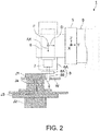
- FIG. 2 is a view for explaining a machining method for outline copying of a workpiece to be machined with attaching a tool to the machining robot shown in FIG. 1 .
- a machining robot 1 is composed of a robot 2 and a control system 3 of the robot 2.
- the robot 2 has an arm 4 having a cantilever structure in which links are connected to each other with a plurality of joints.
- An attachment jig 5 is fixed to the tip of the arm 4.
- a feed structure 6, a spindle 7, a copying guide 8, and a tool T are attached to the attachment jig 5.
- the arm 4 has a structure possible to move the feed structure 6, the spindle 7, the copying guide 8 and the tool T, which are attached to the attachment jig 5, at least two dimensionally.
- the feed structure 6, the spindle 7, the copying guide 8, and the tool T which are attached to the attachment jig 5 can be moved in two-dimensional directions on the plane where the three links are disposed.
- the typical robot 2 has the arm 4 possible to move the feed structure 6, the spindle 7, the copying guide 8, and the tool T, which are attached to the attachment jig 5, in three-dimensional directions as exemplified in FIG. 1 .
- the arm 4 has a structure in which links are coupled to each other with a plurality of rotating mechanisms.
- the feed structure 6, the spindle 7, the copying guide 8, and the tool T which are attached to the attachment jig 5 can be not only moved in parallel three dimensionally but also inclined towards a desired direction by rotation movement.
- the feed structure 6 gives a feed to the tool T in the tool axis AX direction.
- the spindle 7 holds and rotates the tool T. Therefore, the feed structure 6 is configured so that a feeding operation in the tool axis AX direction may be indirectly given to the tool T by giving a feed in the tool axis AX direction to the spindle 7 which holds and rotates the tool T.
- Each of the feed structure 6 and the spindle 7 may be a generalized pneumatic type, hydraulic type, electric type, or another type of device.
- both of the feed structure 6 and the spindle 7 are air pressure type devices. Therefore, the feed structure 6 having the spindle 7 built-in is connected to a compressed air supply tank. As a matter of course, an electric type device may be used for one or both of the feed structure 6 and the spindle 7. In that case, at least one motor included in one or both of the feed structure 6 and the spindle 7 is connected to a power supply.
- the robot 2 has the arm 4 possible to hold and rotate the tool T indirectly by the spindle 7 and move the tool T, which is held by the spindle 7, in two-dimensional or three-dimensional directions. Therefore, a workpiece W can be machined using the tool T by two-dimensional drive or three-dimensional drive of the arm 4.
- Examples of the tool T held by the spindle 7 include not only a chamfering cutter and a deburring tool but also various rotary machining tools, such as an end mill, a drill and a reamer. Therefore, desired cutting work of the workpiece W can be performed by the machining robot 1 to which the rotary tool T has been attached.
- various cutting work including cutting off of the plate-like or block-like workpiece W, outline trim processing, outline rough processing, outline finish processing, groove processing, pocket processing to form a concave portion surrounded by flanges, rough processing of an inside of a flange, finish processing of an inside of a flange, drilling, chamfering and a deburring can be performed.
- examples of material of the workpiece W include composite materials, such as GFRP (Glass Fiber Reinforced Plastics) and CFRP (Carbon Fiber Reinforced Plastics), metals and other desired materials which may be targets for cutting work.
- GFRP Glass Fiber Reinforced Plastics
- CFRP Carbon Fiber Reinforced Plastics
- the copying guide 8 is a jig in the arm 4 side for copying, and therefore, attached in the arm 4 side in order to contact with a copying mold J1 placed in the workpiece W side.
- the copying guide 8 can have not only a guide contacting with the copying mold J1 in the tool diameter direction D for positioning the tool T in the tool diameter direction D, but also a guide contacting with the copying mold J1 in the tool axis AX direction for positioning the tool T in the tool axis AX direction.
- the copying guide 8 has a disk-shaped member 8A and a cylindrical part 8B.
- the disk-shaped member 8A has a through hole for passing the tool T.
- the cylindrical part 8B is coaxially formed on one surface of the disk-shaped member 8A. Then, the copying guide 8 having such a structure is fixed to the casing 6A of the feed structure 6 having the spindle 7 built-in.
- the disk-shaped member 8A functions as the guide for positioning the tool T in the tool axis AX direction by contacting with the copying mold J1 in the tool axis AX direction.
- the cylindrical part 8B functions as the guide for positioning the tool T in the tool diameter direction D by contacting with the copying mold J1 in the tool diameter direction D.
- the tool T can be projected in the workpiece W side through the through hole formed along the center axis of the copying guide 8.
- the copying guide 8 may be rotatably attached to the arm 4 side with a rotating structure, such as a bearing. Nevertheless, when the workpiece W is made of CFRP, powder dust of carbon may jam a clearance in the bearing. For that reason, fixing the copying guide 8 to the arm 4 side without any spindle, such as a bearing, makes it possible to simplify the configuration of the copying guide 8 and prevent powder dust of composite material from entering a rotating structure.
- the copying guide 8 may be rotatably attached to the arm 4 side with a shielded bearing which has a structure to prevent powder dust from entering its inside.
- the form of the copying guide 8 and the position at which the copying guide 8 is attached to the arm 4 can be freely determined according to a form and a position of the copying mold J1 placed in the workpiece W side as well as a form and a position of the workpiece W itself.
- the copying mold J1 is a jig for copying, which is placed in the workpiece W side.
- the copying mold J1 has a surface contacting with the copying guide 8 in the tool diameter direction D and a surface contacting with the copying guide 8 in the tool axis AX direction. Therefore, the tool T can be positioned in both of the tool diameter direction D and the tool axis AX direction by contacting the two contact surfaces of the copying mold J1 with the copying guide 8.
- outline copying of the workpiece W can be performed using the tool T by moving the arm 4 while bringing the copying guide 8 in the arm 4 side in contact with the copying mold J1 placed in the workpiece W side.
- an I-section stringer which is one of aircraft parts is the workpiece W.
- the I-section stringer is a stringer of which cross section is I-shaped.
- the I-section stringer has a structure in which two flanges are formed in both end sides of a web.
- FIG. 2 shows an example where an I-section stringer is produced by cutting off a flange part of material of which cross section is I-shaped.
- one flange which is the lower part of the workpiece W is placed on a platy jig J3 fixed on a work table J2. Furthermore, the platy copying mold J1 is placed on the other flange which is the upper part of the workpiece W.
- the form of the copying mold J1 is offset from the form of the workpiece W after machining, by a distance between the surface of the copying guide 8 contacting with the copying mold J1 and a cutting face of the tool T. That is, an end face is formed on the copying mold J1 so that the end face becomes offset from a position of the end face of the flange after machining, by a constant distance according to a structure of the copying guide 8.
- the diameter of the cylindrical part 8B of the copying guide 8 can be determined to 14 mm to 15 mm.
- the distance between the side face of the cylindrical part 8B of the copying guide 8 and the cutting face of the tool T is 2 mm to 2.5 mm. Therefore, the offset amount between the end face of the copying mold J1 and the form of the workpiece W after machining is set to 2 mm to 2.5 mm.
- the arm 4 can be moved with making the stepped cylindrical copying guide 8 attached in the arm 4 side contact with the platy copying mold J1 placed in the workpiece W side. Thereby, outline trim copying processing by which a platy part of the workpiece W is cut off with the tool T, such as an end mill or a router bit, can be performed.
- the tool T such as an end mill or a router bit
- copying of the workpiece W with precisely positioning the tool T in the tool diameter direction D perpendicular to both of the feed direction F of the tool T and the tool axis AX can be performed by moving the arm 4 while making the curved surface of the cylindrical part 8B of the copying guide 8 contact on the end face of the platy copying mold J1.
- copying of the workpiece W with precisely positioning the tool T in the tool axis AX direction can be performed by moving the arm 4 while making the plane surface of the disk member 8A of the copying guide 8 contact on the upper surface of the platy copying mold J1.
- the structure of the copying mold J1 for the outline copying can be a simple platy structure when the structure of the copying guide 8 is a stepped cylindrical structure.
- copying can be performed for a part having a desired structure.
- a spar, a rib, a panel or an assembly thereof as well as a stringer having various cross section forms, such as I-section, T-section and hat-shaped can be the workpiece W to be an object of copying.
- outline copying such as outline trim processing of a panel, trim processing of an end face of a flange, inner surface processing of a flange and outer surface processing of a flange
- outline copying with the machining robot 1 can be performed in order to produce a desired product or semi-product, such as an automobile part or a railroad vehicle part, as well as an aircraft part.
- the form and position of the copying mold J1 can also be determined freely according to a form and position of the workpiece W as well as the form and position of the copying guide 8 attached in the arm 4 side.
- the arm 4 is provided with force sensors 9 for detecting forces applied on the arm 4.
- the force sensors 9 detect forces applied on the arm 4 at least from the tool T. Specifically, when outline working of the workpiece W is performed by the cutting edges formed on the side face of the tool T, a reaction force, including main components in the feed direction F of the tool T and the tool diameter direction D perpendicular to the feed direction F of the tool T, acts on the tool T from the workpiece W.
- a reaction force including components in not only the feed direction F of the tool T and the tool diameter direction D perpendicular to the feed direction F of the tool T but also in the tool axis AX direction, acts on the tool T from the workpiece W.
- a reaction force having main components in the tool axis AX direction and the tool diameter direction D acts on the copying guide 8 from the copying mold J1.
- a three-dimensional reaction force consisting of components in the feed direction F of the tool T, the tool diameter direction D perpendicular to the feed direction F of the tool T and the tool axis AX direction, is applied on the arm 4 indirectly through the tool T, the spindle 7 and the feed structure 6.
- the force sensors 9 possible to detect forces in three axis directions orthogonal to each other can be attached to the attachment jig 5 on the tip of the arm 4.
- the attachment jig 5 has been attached to the arm 4 via the stepped disk-like force sensors 9.
- the forces applied on the arm 4 from the tool T can be detected by the force sensors 9.
- the forces applied on the arm 4 from the copying mold J1 during the outline copying of the workpiece W can also be detected by the force sensors 9.
- the attaching direction of the tool T, the spindle 7, and the feed structure 6 to the arm 4 can be freely determined according to the respective structures of the workpiece W, the copying guide 8 and the copying mold J1.
- the tool diameter direction D perpendicular to the feed direction F of the tool T and the tool axis AX direction are made to coincide with or made related to three axis directions in which the force sensors 9 can detect forces, the respective components of the reaction force in the feed direction F of the tool T, the tool diameter direction D perpendicular to the feed direction F of the tool T and the tool axis AX direction can be detected by the force sensors 9.
- the tool T when the forces in the X axis direction, the Y axis direction and the Z axis direction orthogonal to each other can be detected by the force sensors 9, as shown in FIG. 2 , the tool T can be attached to the arm 4 so that the feed direction F of the tool T may be parallel to the X axis direction, the tool diameter direction D perpendicular to the feed direction F of the tool T may be parallel to the Y axis direction and the tool axis AX direction may be parallel to the Z axis direction.
- the forces detected by the force sensors 9 respectively are output to the control system 3.
- the control system 3 is configured to control the arm 4 based on the forces detected by the force sensors 9 respectively.
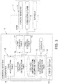
- FIG. 3 is a functional block diagram of the control system 3 included in the machining robot 1 shown in FIG. 1 .
- the control system 3 can be composed of an input device 10, a display 11 and a computer 12 to which the input device 10 and the display 11 are attached.
- the processing unit, such as CPU (central processing unit), of the computer 12 functions as a load acquisition part 13, a control signal generation part 14, a control information storage part 15 and a warning information generation part 16 by reading and executing control program of the robot 2.
- the control system 3 also has an arm control part 17 and a tool control part 18.
- the arm control part 17 may be provided as a function of the computer 12. That is, common processing circuitry may be used for having control program for configuring the arm control part 17 read, in addition to for providing the functions of the load acquisition part 13, the control signal generation part 14, the control information storage part 15 and the warning information generation part 16.
- the load acquisition part 13 has a function to obtain the forces detected by the force sensors 9 and notify the control signal generation part 14 and the warning information generation part 16 of the obtained force.
- the load acquisition part 13 obtains the forces, consisting of force component in the feed direction F of the tool T, force component in the tool diameter direction D perpendicular to the feed direction F of the tool T and force component in the tool axis AX direction, from the force sensors 9 and the obtained forces having the components in the three directions are notified to the control signal generation part 14 and the warning information generation part 16.
- the control signal generation part 14 has a function for controlling the arm 4, the feed structure 6 and the spindle 7 based on machining control program stored as control information in the control information storage part 15.
- machining control program which consists of control program of the arm 4, control program of the feed structure 6 and control program of the spindle 7 can be generated and the generated machining control program can be stored as control information of the machining robot 1 in the control information storage part 15.
- control signal generation part 14 can have a function to refer to the machining control program stored in the control information storage part 15 to generate the respective control signals of the arm 4, the feed structure 6 and the spindle 7 according to the machining control program so that the generated control signal of the arm 4 can be output to the drive part of the arm 4 through the arm control part 17 while the generated control signals of the feed structure 6 and the spindle 7 can be output to the feed structure 6 and the spindle 7 through the tool control part 18 respectively.
- control signal generation part 14 has a function to generate control signals of the arm 4 for outline copying, based on the forces notified from the load acquisition part 13 and control program of the arm 4 for the outline copying, and to automatically control the arm 4 by outputting the generated control signals to the arm 4 so that the outline copying may be performed.
- the control program of the arm 4 for outline copying teaches an orbital and movement speed of the arm 4 so that the copying guide 8 may move while contacting with the copying mold J1. That is, the control program for outline copying teaches a moving direction and moving speed of the arm 4 by designating teaching positions and teaching speeds. Therefore, the control program for outline copying is generated based on form information of the copying mold J1.
- control program for outline copying which teaches spatial positions and moving directions of the arm 4 can be generated based on spatial positions of the surface of the copying mold J1 contacting with the copying guide 8.
- control program for outline copying which teaches spatial positions and moving directions of the arm 4 can be generated based on two dimensional or three dimensional form information of the surface of the copying mold J1 contacting with the copying guide 8.
- the generated control program of the arm 4 for outline copying can be stored in the control information storage part 15 so that the control signal generation part 14 can refer to the control program in a case of performing the outline copying of the workpiece W.
- control signal generation part 14 is configured to generate control signals of the arm 4 not only based on control program of the arm 4 for outline copying but based on the forces obtained from the force sensors 9 through the load acquisition part 13, in a case of performing outline copying of the workpiece W.
- the control signal generation part 14 can obtain forces, having components consisting of force in the feed direction F of the tool T, force in the tool diameter direction D perpendicular to the feed direction F of the tool T and force in the tool axis AX direction, from the force sensors 9 through the load acquisition part 13.
- the force in the feed direction F of the tool T, the force in the tool diameter direction D perpendicular to the feed direction F of the tool T and the force in the tool axis AX direction can be obtained directly based on the forces consisting of three orthogonal components obtained from the force sensors 9 through the load acquisition part 13.
- the force sensors 9 can detect forces, by an unchanged known angle or unchanged known angles, the force in the feed direction F of the tool T, the force in the tool diameter direction D perpendicular to the feed direction F of the tool T and the tool axis AX direction can be obtained by coordinate transformation processing.
- the force in the feed direction F of the tool T, the force in the tool diameter direction D perpendicular to the feed direction F of the tool T and the force in the tool axis AX direction can be calculated by coordinate transformation processing.
- FIG. 4 explains a method for obtaining the reaction force in the feed direction F and the reaction force in the tool diameter direction D of the tool T when the feed direction F of the tool T changes during outline copying using the machining robot 1 shown in FIG. 2 .
- the feed direction F of the tool T changes in a tangential direction of the outline form of the workpiece W after machining and the copying mold J1, as shown in FIG. 4 .
- the direction of the reaction force acting on the copying guide 8 in the tool diameter direction D becomes a normal direction perpendicular to the cut surface of the workpiece W, i.e., the surface of the workpiece W after machining and the surface of the copying mold J1.
- a direction perpendicular to the face of the workpiece W after machining or the face of the copying mold J1 can be specified, as the tool diameter direction D in which the tool T and the copying guide 8 receive reaction forces from the workpiece W and the copying mold J1 respectively, based on a two dimensional form of the copying mold J1 or the workpiece W after machining.
- a direction perpendicular to the face of the workpiece W and the face of the copying mold J1 may be specified, as the tool diameter direction D in which the tool T and the copying guide 8 receive reaction forces from the workpiece W and the copying mold J1 respectively, based on teaching positions of the tool T identified based on the control program of the arm 4.
- a reaction force in the specified tool diameter direction D can be calculated by vector calculation based on respective detection values of forces in the X axis direction and the Y axis direction.
- FIG. 5 shows an example case where the directions of the force sensors 9 change even when the feed direction F of the tool T does not change during outline copying using the machining robot 1 shown in FIG. 2 .
- the directions of the force sensors 9 change depending on positions of driving shafts included in the arm 4 even when the feed direction F of the tool T does not change during outline copying. Specifically, in a case where the force sensors 9 cannot be moved in parallel in the feed direction F of the tool T caused by restrictions in the driving shafts of the arm 4, directions of the force sensors 9 change even when the feed direction F of the tool T is linear and does not change.
- a direction perpendicular to the face of the workpiece W and the face of the copying mold J1 can be also specified, as the tool diameter direction D in which the tool T and the copy guide 8 receive reaction forces from the workpiece W and the copying mold J1 respectively, based on a form of the copying mold J1 in addition to a form of the workpiece W after machining or teaching positions of the tool T. Then, a reaction force in the specified tool diameter direction D can be calculated by vector calculation based on respective detection values of forces in the X axis direction and the Y axis direction.
- the feed direction F of the tool T, the tool diameter direction D perpendicular to the feed direction F of the tool T and the tool axis AX direction may be detected based on time changes in forces detected as three vector components by the force sensors 9.
- a force in the feed direction F of the tool T, a force in the tool diameter detection D perpendicular to the feed direction F of the tool T and a force in the tool diameter AX direction can be obtained without the form information on the copying mold J1 and the workpiece W.
- the control signal generation part 14 has a function to obtain a force in the feed direction F of the tool T, a force in the tool diameter direction D perpendicular to the feed direction F of the tool T and a force in the tool axis AX, based on forces detected by the force sensors 9, under the above-mentioned method. Thereby, the control signal generation part 14 can control the arm 4 according to directions of forces applied on the arm 4.
- reaction force from the workpiece W to the tool T increases in a case where the thickness of the platy workpiece W changes or cutting width of the workpiece W become larger even when the feeding speed in the feed direction F of the tool T is constant. Furthermore, the reaction force from the workpiece W to the tool T also increases when the tool T has been worn out and sharpness of the tool T has deteriorated.
- a vibration such as a chatter vibration
- the surface roughness of each machined face becomes rough and that leads to quality degradation of a product or a semi-product obtained as the workpiece W after machining even when the product or the semi-product has been produced by outline copying using he copying guide 8 and the copying mold J1.
- an ideal feeding speed in the feed direction F of the tool T changes depending on processing conditions of the workpiece W when processing quality of the workpiece W is secured while processing efficiency of the workpiece W is improved at the same time.
- control signal generation part 14 can be configured to generate control signals of the arm 4 for outline copying, based on the force in the feed direction F of the tool T directly measured by one of the force sensors 9 or indirectly obtained with processing, such as coordinate transformation, using the force sensors 9 so that the feed speed of the tool T becomes to a predetermined control value. That is, the feed speed of the tool T can be automatically adjusted so that the reaction force in the feed direction F of the tool T may not be excessive during outline copying.
- Concrete examples of a method of automatically adjusting the feed speed of the tool T include a method of automatically controlling the feed speed of the tool T so that the reaction force in the feed direction F of the tool T may be within a predetermined range.
- control signal generation part 14 has only to determine a control value of the feed speed of the tool T so that the force in the feed direction F of the tool T obtained using at least one of the force sensors 9 may become constant or within a predetermined range, and generate control signals of the arm 4 for outline copying so that the feed speed of the tool T may become the determined control value of the feed speed of the tool T. That is, what is necessary is to perform a feedback control of the feed speed of the tool T by which the force in the feed direction F of the tool T is made constant or within a predetermined range.
- the movement speed of the arm 4 should be automatically adjusted so that the reaction force to the carbide tool may be not less than 3 kgf and not more than 5 kgf.
- the reaction force to the carbide tool may be not less than 3 kgf and not more than 5 kgf.
- the cemented carbide is obtained by sintering tungsten carbide powder, to which additive materials, such as titanium carbide and/or tantalum carbide, have been added, with cobalt.
- a diamond tool is obtained by molding a single crystal of diamond or made of a polycrystalline sintered body obtained by sintering diamond fine powder to which an additive material, such as cobalt, has been added.
- Another concrete example of the method of automatically adjusting the feed speed of the tool T is a method of changing the feed speed of the tool T to a speed preset according to the force in the feed direction F of the tool T.
- FIG. 6 shows a graph for explaining a method for controlling the arm 4 of the machining robot 1 shown in FIG. 1 .
- the horizontal axis shows detected values of the force (kgf) applied in the feed direction F of the tool T while the vertical axis shows control values of the feed speed of the tool T.
- a table or function relating to forces, applied on the arm 4 in the feed direction F of the tool T, with control values of the feed speeds of the tool T can be prepared.
- the created table or function can be stored in the control information storage part 15.
- the feed speed of the tool T has been determined to be a teaching speed given as a parameter in control program by a user since the reaction force from the workpiece W is small. Meanwhile, when the force in the feed direction F of the tool T is not less than 5.5 kgf, the feed speed of the tool T has been determined to be 50 % of the teaching speed from a viewpoint of suppressing vibration of the tool T since the reaction force from the workpiece W is large.
- FIG. 6 shows an example case where feed speed control program of the tool T has been generated so that the feed speed of the tool T may automatically slow down gradually to 50 % of a teaching speed when the force in the feed direction F of the tool T exceeds a threshold value.
- forces applied on the arm 4 from the feed direction F of the tool T may be related to control values of feed speeds of the tool T by a desired function or the like according to a result of cutting examination or the like, not limited to an example shown in FIG. 6 .
- the control value of feed speed of the tool T can be decreased in a stepwise shape or a curved shape.
- a table in which numerical values of forces applied from the feed direction F of the tool T have been related with numerical control values of feed speeds of the tool T may be prepared.
- control signal generation part 14 can determine a control value of feed speed of the tool T, corresponding to the force in the feed direction F of the tool T obtained actually using the force sensors 9 during outline copying, based on the table or the function stored in the control information storage part 15.
- control signal generation part 14 can generate control signals of the arm 4 for outline copying so that the feed speed of the tool T may become the determined control value of feed speed of the tool T.
- control signal generation part 14 may have a function to generate control signals for stopping movement of the arm 4 to output the generated control signals to the arm control part 17 when the force in the feed direction F of the tool T obtained by the load acquisition part 13 has become not less than a threshold value or has exceeded a threshold value.
- control for stopping movement of the arm 4 can also be performed when at least one of the force in the tool diameter direction D perpendicular to the feed direction F of the tool T and the force in the tool axis AX direction has become not less than a threshold value or has exceeded a threshold value, from a viewpoint of avoiding an interference between the tool T and the copying guide 8 or the like because of a setting error of the workpiece W and/or the copying mold J1.
- control signal generation part 14 can obtain not only the reaction force in the feed direction F of the tool T but also the reaction force in the tool diameter direction D perpendicular to the feed direction F of the tool T and the reaction force in the tool axis AX direction.
- control signal generation part 14 can perform not only feedback control of the arm 4 based on the reaction force in the feed direction F of the tool T but also feedback control of the arm 4 based on the reaction force in the tool diameter direction D perpendicular to the feed direction F of the tool T and feedback control of the arm 4 based on the reaction force in the tool axis AX direction.
- the rigidity of the arm 4 having a cantilever structure is extremely small compared with the rigidity of a spindle of a machine tool. Therefore, an error arises between an actual position of the tool T and a teaching position of the tool T directed by control program, due to bending of the arm 4 caused by the reaction force by cutting, the own weight and the like, if the arm 4 is controlled only according to the control program.
- Such an error caused by positioning accuracy of the arm 4 is not negligible for cutting work of the workpiece W requiring processing accuracy in which a tolerance is about ⁇ 0.1 mm to ⁇ 1.0 mm.
- the copying guide 8 may not contact with the copying mold J1 steadily if the arm 4 is controlled only according to control program.
- control signal generation part 14 can determine a control value of position of the tool T in the tool diameter direction D perpendicular to the feed direction F of the tool T so that the force, in the tool diameter direction D perpendicular to the feed direction F of the tool T, obtained using the force sensors 9 may become constant or within a predetermined range.
- correction for offsetting teaching positions of the tool T instructed by control program in the tool diameter direction D perpendicular to the feed direction F of the tool T can be performed so that the reaction force in the tool diameter direction D perpendicular to the feed direction F of the tool T may become constant or within a predetermined range, and the corrected positions by the correction can be set as control values of the positions in the tool diameter direction D perpendicular to the feed direction F of the tool T.
- control signals of the arm 4 for outline copying can be generated and output to the arm control part 17 so that the positions of the tool T in the tool diameter direction D perpendicular to the feed direction F of the tool T may become the set control values of the positions in the tool diameter direction D perpendicular to the feed direction F of the tool T.
- a feedback control of the arm 4 can be performed so that the reaction force in the tool diameter direction D, applied on the copying guide 8 and the tool T from the copying mold J1 and the workpiece W, may become constant or within a predetermined range.
- the copying guide 8 can be certainly pressed against the copying mold J1 in the tool diameter direction D, with an appropriate force which is constant or within a predetermined range, during copying.
- control signal generation part 14 can determine a control value of position in the tool axis AX direction of the tool T so that the force in the tool axis AX direction of the tool T obtained using the force sensors 9 may become constant or within a predetermined range.
- correction for offsetting teaching positions of the tool T instructed by the control program so that the reaction force in the tool axis AX direction may become constant or within a predetermined range and the corrected positions by the correction can be set as control values of positions of the tool T in the tool axis AX direction of the tool T.
- control signals of the arm 4 for outline copying can be generated and output to the arm control part 17 so that the positions of the tool T in the tool axis AX direction of the tool T may be the set control values of the positions in the tool axis AX direction of the tool T.
- a feedback control of the arm 4 can be performed so that the reaction force in the tool axis AX direction, applied on the copying guide 8 from the copying mold J1, may become constant or within a predetermined range.
- the copying guide 8 can be certainly pressed against the copying mold J1 in the tool axis AX direction, with an appropriate force which is constant or within a predetermined range, during copying.
- the copying mold J1 and the workpiece W have to have strengths not so as to be deformed by the applied force respectively.
- the control signal generation part 14 can automatically control the feed structure 6 based on the reaction force of the tool T in the tool axis AX direction obtained using the force sensors 9.
- Typical examples of positioning of the tool T in the tool axis AX direction preferably performed by operation of the feed structure 6A include drilling. This is because the positioning of the tool T in the tool axis AX direction by linear operation of the feed structure 6 is far accurate compared with that by linear movement of the arm 4 accompanied by interpolation processing, for drilling.
- the control signal generation part 14 can determine a control value of feeding speed of the feed structure 6 so that the force in the tool axis AX direction of the tool T obtained using the force sensors 9 may be constant or within a predetermined range, and generate control signals for drilling of the feed structure 6 to output them to the feed structure 6 so that the feeding speed of the feed structure 6 becomes the determined control value of the feeding speed.
- drilling the workpiece W by the tool T can be performed with the reaction force in the tool axis AX direction of the tool T as constant as possible.
- the arm control part 17 of the control system 3 has a function to control the arm 4 by outputting control signals of the arm 4, generated by the control signal generation part 14, to the respective drive parts of the arm 4.
- the tool control part 18 has a function to control the feed structure 6 and the spindle 7 by outputting control signals of the feed structure 6 and the spindle 7, generated by the control signal generation part 14, to the feed structure 6 and the spindle 7 respectively.
- the tool control part 18 is provided with a function to convert control signals generated by the control signal generation part 14, from electric signals to air signals, to output the converted control signals to the feed structure 6 and the spindle 7 respectively.
- the warning information generation part 16 has a function to obtain the force in the feed direction F of the tool T, based on the forces obtained by the load acquisition part 13, and to output warning information as a warning message to the display 11 when the force in the feed direction F of the tool T has been not less than a threshold value or has exceeded a threshold value.
- the warning information may be output to an output device, such as a lamp or a speaker, as lights, a warning sound or a voice message, instead of the display 11 or in addition to the display 11.
- warning information can be output before the arm 4 stops.
- warning information can be also output before the arm 4 stops when one of the force in the tool diameter direction D perpendicular to the feed direction F of the tool T and the force in the tool axis AX direction has become not less than a threshold value or more than a threshold value, from a viewpoint of avoiding interference between the tool T and the copying guide 8 by failure in setting the workpiece W and the copying mold J1, or the like.
- a threshold value for determining whether warning information should be output, in the warning information generation part 16, is set to be lower than that for determining whether the arm 4 should be stopped, in the control signal generation part 14.
- the warning information generation part 16 can be adapted to output warning information when the force obtained by the load acquisition part 13 has been not less than or more than the first threshold value while the control signal generation part 14 can be adapted to stop movement of the arm 4 when the force obtained by the load acquisition part 13 has not less than or more than the second threshold value larger than the first threshold value.
- the first threshold value and the second threshold value are set for each of the force in the feed direction F of the tool T, the force in the tool diameter direction D perpendicular to the feed direction F of the tool T and the force in the tool axis AX direction.
- control program for making the control system 3 execute a step for obtaining the forces applied on the arm 4, detected by the force sensors 9 during outline copying; and a step for generating control signals of the arm 4 for the outline copying, based on the obtained forces and control information of the arm 4 for the outline copying, and automatically controlling the arm 4 by outputting the generated control signals to the arm 4 so that the outline copying are performed can be distributed as a program product.
- the control function for outline copying can be added to a conventional robot by making a control system of the conventional robot read the control program of the robot 2. Therefore, the machining robot 1 can be configured by attaching the feed structure 6, the spindle 7, the copying guide 8 and the tool T to the conventional robot.
- the workpiece W is set and the copying mold J1 is set at a predetermined position in the workpiece W side.
- the workpiece W is fixed to the platy jig J3 fixed on the work table J2 and the copying mold J1 is fixed on the workpiece W, as shown in FIG. 2 .
- the feeding structure 6, the spindle 7, the copying guide 8 and the rotating tool T are attached to the arm 4, having the force sensors 9, with the attaching jig 5.
- control program for teaching a track of the arm 4 so as to move the copying guide 8 in contact with the copying mold J1 is created by a user.
- the created control program of the arm 4 is written in the control information storage part 15 by operation of the input device 10 as machining control program, together with control program of the feed structure 6 and control program of the spindle 7.
- the control signal generation part 14 generates initial control signals of the arm 4. for moving the tool T along a pass which has been offset, as much as the thickness of the copying guide 8, from the end face of the copying mold J1.
- the generated initial control signals of the arm 4 are output to the driving parts of the arm 4 through the arm control part 17.
- control signal generation part 14 generates control signals of the feed structure 6 and the spindle 7 respectively so that the tool T may rotate in a state where the tip of the tool T has been fed to a required position.
- the generated control signals of the feed structure 6 and the spindle 7 are output to the feed structure 6 and the spindle 7 through the tool control part 18 respectively.
- the arm 4 moves so that the tool T moves to an initial teaching position. Meanwhile, the tip of the tool T is fed to the required position and the tool T rotates.
- the control signal generation part 14 continuously generates control signals of the arm 4 for moving the tool T along a taught track, according to the control program.
- the generated control signals of the arm 4 are output to the driving parts of the arm 4 through the arm control part 17. Consequently, the arm 4 moves so that the tool T advances in a direction taught by the control program in a state where the copying guide 8 is in contact with the copying mold J1. Thereby, the outline copying of the workpiece W by the rotating tool T is started.
- the components of the force applied on the arm 4 from the tool T during the outline copying are detected by the force sensors 9 attached to the arm 4.
- the components of the force detected by the force sensors 9 are output to the control system 3 of the robot 2.
- the load acquisition part 13 obtains detection values of the components of the force, output from the force sensors 9, and gives them to the control signal generation part 14.
- control signal generation part 14 detects a force in the feed direction F of the tool T, a force in the tool diameter direction D perpendicular to the feed direction F of the tool T and a force in the tool axis AX direction respectively, based on the obtained detection values of the components of the force output from the force sensors 9.
- control signal generation part 14 automatically controls the arm 4 based on the force in the feed direction F of the tool T, the force in the tool diameter direction D perpendicular to the feed direction F of the tool T and the force in the tool axis AX direction.
- control signal generation part 14 generates control signals of the arm 4 for the outline copying, based on not only the control program of the arm 4 for the outline copying but the forces obtained from the load acquisition part 13.
- the generated control signals of the arm 4 are output to the drive parts of the arm 4 through the arm control part 17. Thereby, the outline copying is carried out with a force control of the arm 4.
- the moving speed of the arm 4 and the tool T is automatically adjusted based on the force in the feed direction F of the tool T.
- a feedback control of the moving speed of the arm 4 and the tool T is carried out so that the reaction force in the feed direction F of the tool T may be constant or within a predetermined range.
- the feed speed of the tool T is decreased so as to be slower than a teaching speed of the tool T designated as a parameter in the control program of the arm 4.
- positions of the arm 4 and the tool T are automatically adjusted based on the force in the tool diameter direction D perpendicular to the feed direction F of the tool T and the force in the tool axis AX direction. Specifically, the positions of the arm 4 and the tool T are finely adjusted so that each of the force in the tool diameter direction D perpendicular to the feed direction F of the tool T and the force in the tool axis AX direction may be constant or within a predetermined range.
- the workpiece W having more accurate sizes can be machined.
- the workpiece W can be machined with processing accuracy in which a tolerance is about ⁇ 0.1 mm to ⁇ 1.0 mm.
- the machining robot 1, as an example of a machining apparatus, and the machining method perform outline copying of the workpiece W by bringing the copying guide 8 attached to the arm 4 side of the robot 2 into contact with the copying mold J1 placed on the workpiece W, while controlling movement of the arm 4 based on processing reaction forces detected by the force sensors 9.
- a movement speed of the tool T and the arm 4 is controlled so that the reaction force in the feed direction F of the tool T may not become excessive while the arm 4 is controlled so that each of the reaction force in the tool diameter direction D perpendicular to the feed direction F of the tool T and the reaction force in the tool axis AX direction may become constant or within a predetermined range.
- the control system 3 and the control method of the robot 2 can control the arm 4 of the robot 2 for the above-mentioned outline copying.
- the machining robot 1 and the machining method can perform heavy cutting working, such as outline trim processing, outline rough processing, outline finish processing, groove processing, pocket processing and drilling, of the workpiece W, with a large reaction force from the workpiece W, with high accuracy in spite of using the robot 2.
- machining of the workpiece W can be automated without placing a large scale machine tool.
- the tool T attached to the arm 4 of the robot 2 having low positioning accuracy compared with a machine tool can be positioned with high accuracy by copying while making the copying guide 8 attached to the arm 4 side of the robot 2 in contact with the copying mold J1 place on the workpiece W.
- the copying guide 8 can always be brought into contact with the copying mold J1, with proper pressing forces in both the tool diameter direction D and the tool axis AX direction each perpendicular to the feed direction F of the tool T, by controlling the arm 4 so that each of the reaction forces in the tool diameter direction D and the tool axis AX direction may become constant or within a predetermined range.
- vibration of the tool T held by the arm 4 of the robot 2 having low rigidity compared with rigidity of a spindle of a machine tool can be suppressed since the moving speed of the tool T and the arm 4 is automatically adjusted so that the reaction force in the feed direction F of the tool T may not become excessive.
- machining quality similar to that obtained by a machine tool can be obtained using the robot 2 extremely inexpensive compared with a machine tool.
- the moving speed of the tool T and the arm 4 can be automatically adjusted appropriately so as to follow the reaction forces from the workpiece W even when the plate thickness of the workpiece W is not constant and/or the reaction forces from the workpiece W do not become constant because of wear of the tool T or the like.
- FIG. 7 is a sectional view showing a detailed example of structure of a copying guide attached to a machining robot as an example of machining apparatus according to the second embodiment of the present invention.
- the machining robot 1A in the second embodiment shown in FIG. 7 is different from the machining robot 1 in the first embodiment in the point that a copying guide 20 for being contacted with the copying mold J1 placed in the workpiece W side has a function to prevent scattering of cut chips and an air cooling function.
- a structure of the copying guide 20 is mainly illustrated together with the feed structure 6 and the spindle 7 to be attached to the arm 4 as exemplified in FIG. 1 , and explanations for the same or corresponding elements will be omitted with attaching the same signs.
- the copying guide 20 in the machining robot 1A side is also attached to the feed structure 6, which gives the tool T a feed in the tool axis direction AX, and the spindle 7, which holds and rotates the tool T. Also in an example shown in FIG. 7 , the copying guide 20 has been fixed to the casing 6A of the feed structure 6, similarly to an example shown in FIG. 1 .
- FIG. 8 shows a state where the tool T and the spindle 7 have been fed out in the tool axis AX direction by the feed structure 6 shown in FIG. 7 .
- the copying guide 20 in the second embodiment also has a disk member 20A and the first cylindrical part 20B along the same axis, and has a through hole for passing the tool T through along the center line, similarly to the copying guide 8 in the first embodiment.
- the disk member 20A functions as a guide for positioning the tool T in the tool axis direction AX of the tool T by contacting with the copying mold J1 in the tool axis direction AX as shown in FIG. 8 .
- the first cylindrical part 20B functions as a guide for positioning the tool T in the tool diameter direction D of the tool T by contacting with the copying mold J1 in the tool diameter direction D as shown in FIG. 8 .
- the copying guide 20 in the second embodiment has an air supply passage 21 for supplying air injected toward the workpiece W side through a clearance between the tool T and the through hole for passing the tool T through.
- the copying guide 20 in the second embodiment is provided with the second cylindrical part 20C for forming the air supply passage 21 in the spindle 7 side of the disk member 20A, for example.
- an air supply port 21A for forming the air supply passage 21 can be formed on the second cylindrical part 20C.
- the air supply port 21A is a through hole which opens the through hole, for passing the tool T through, toward the outside, at the second cylindrical part 20C. Therefore, air can be supplied from the air supply port 21A into the through hole for passing the tool T through.
- a flow of the air can be formed so that the air flows from the copying guide 20 toward the workpiece W side through the air supply port 21A and the subsequent clearance between the tool T and the through hole for passing the tool T through.
- the air supply port 21A can be formed by a coupler or the like for coupling the second cylindrical part 20C to a compressed air supply tank with an air supplying hose, as shown in FIG. 8 . Then, the air supply port 21A can be connected to the compressed air supply tank with a hose.
- chips such as powder dust of a composite material or metal chips, generated by cutting can be blown away in the air ejection direction. Thereby, the chips can be prevented from not only dispersing around but dispersing to enter the clearance between the tool T and the copying guide 20.
- the tool T can also be cooled by the air since the air flows along with the tool T. Thereby, the wear of the tool T and the degradation in machining quality due to temperature rise of the tool T are avoidable.
- a pan 22 for collecting chips blown away by the air ejected toward the workpiece W side can be placed at a blowout destination of the air.
- the pan 22 has been disposed under the workpiece W so that the pan 22 may not interfere with the tool T.
- a dust suction duct 24 can be coupled to the pan 22 in order to suck the chips, collected by the pan 22, by a dust collector 23. Thereby, not only scattering of the chips to the surrounding area due to rotation of the tool T can be prevented, but also the chips can be collected by the dust collector 23. In particular, when the workpiece W is made of CFRP, the scattering of carbon dust can be prevented effectively by the suction force of the dust collector 23 while the carbon dust can be collected.
- the length of the copying guide 20 in the tool axis AX direction becomes long. Therefore, the through hole for passing the tool T through also becomes long.
- the length of the tool T it is necessary for machining workpiece W to secure the length of the tool T so that the tool T may project by a sufficient length from the copying guide 20.
- the tool T which has such a length as a whole that the length of the projecting part of the tool T from the copying guide 20 may be longer than the thickness or the length of the workpiece W in the tool axis AX direction.
- the bearing 25 for stopping the wobbling can be disposed inside the through hole, for passing the tool T through, of the copying guide 20, for example. Thereby, the necessity of the further increase in the tool length in order to dispose the bearing 25 can be avoided. In other words, the interference of the spindle 7 with the bearing 25 is avoidable.
- the bearing 25 When the bearing 25 is used for preventing the tool T from wobbling, it is appropriate to determine the inner diameter of the inner ring composing the bearing 25 so that the fit tolerance between the inner diameter of the inner ring and the diameter of the tool T corresponds to a clearance fit.
- the clearance fit is a fit by which a clearance is formed constantly when a shaft is combined with a hole.
- the clearance fit is a fit by which the minimum size of a hole is larger than the maximum size of a shaft.
- a tolerance of the inner diameter of the inner ring composing the bearing 25 should be set to be a tolerance corresponding to F7 or F8 under Japanese Industrial Standards in order to fit the tool T with the inner ring by a clearance fit.
- the air supply passage 21 for taking in air may be formed in another part, such as the casing 6A of the feed structure 6. Nevertheless, a structure that the bearing 25 is disposed inside the through hole of the copying guide 20 while the air supply port 21A is formed at a position, in the workpiece W side of the bearing 25, on the copying guide 20 allows leading a sufficient amount of air to the workpiece W side since the clearance between the bearing 25 and the tool T is small.
- the above-mentioned copying guide 20 having the air supply passage 21 can be provided as an attachment for the robot 2 including the arm 4, having a cantilever structure, to which the spindle 7 and the feed structure 6 have been attached.
- the machining apparatus itself composed of the spindle 7 and the feed structure 6 of the tool T to which the air supply passage 21 and the copying guide 20 have been formed and attached respectively may be provided as an attachment for the robot 2 including the arm 4 having a cantilever structure.
- the air supply passage 21 and the copying guide 20 are used for outline copying
- the air supply passage 21 and the copying guide 20 are attached to the spindle 7 and the feed structure 6 attached to the arm 4 of the robot 2.
- the spindle 7 and the feed structure 6 having the air supply passage 21 and the copying guide 20 are attached to the arm 4 of the robot 2.
- the copying mold J1 is placed in the workpiece W side. Then, the outline copying of the workpiece W is performed using the tool T by moving the arm 4 of the robot 2 while making the copying guide 20 contact with the copying mold J1. That is, a product or a partially-processed product can be produced by the outline copying of the workpiece W.
- air can be supplied in the copying guide 20 through the air supply passage 21 during the outline copying.
- air supply port 21A formed on the copying guide 20 forms the air supply passage 21 as exemplified in FIG. 7 and FIG. 8
- air can be supplied inside the copying guide 20 from the air supply port 21A, and the supplied air can be injected towards the workpiece W through the clearance between the copying guide 20 and the tool T.
- chips generated by the outline copying can be prevented from scattering while the tool T can be cooled by the air.
- a force applied on the arm 4 from at least the tool T during the outline copying may be detected by the force sensors 9 and the moving speed of the arm 4 may be automatically adjusted based on the forces detected by the force sensors 9, also in the second embodiment, similarly to the first embodiment.
- the above-mentioned machining robot 1A and machining method in the second embodiment can prevent chips from scattering and air-cool the tool T, by blowing off air from the clearance between the tool T and the copying guide 20 for copying.
- the machining robot 1A and the machining method in the second embodiment can achieve effects that chips can be prevented from scattering and the tool T can be air-cooled, in addition to effects similar to the effects achieved by the machining robot 1 and the machining method in the first embodiment.
- a tool which is not a rotating type may be attached to the arm 4 of the robot 2 for machining the workpiece W although a case where the rotating tool T is attached to the arm 4 of the robot 2, with the spindle 7, for machining the workpiece W has been explained in the first embodiment mentioned above.
- the workpiece W may be cut off by attaching a saw, such as a band saw or a wire saw, to the arm 4 of the robot 2.
- a saw such as a band saw or a wire saw
- copying can be performed by attaching a copying guide to the arm 4 and placing a copying mold in the workpiece W side.
- the arm 4 can be automatically controlled based on reaction forces from the workpiece W and the copying mold, measured by the force sensors 9.
- an attachment having the copying guide 20 and the air supply passage 21 may be used to be attached to another machining apparatus.
- an attachment having the copying guide 20 and the air supply passage 21 may be attached to a machining apparatus including a handheld drill driving device, an automatic drilling machine and a machining tool, such as a drill press or a milling machine.
- an attachment having the copying guide 20 and the air supply passage 21 may be attached to a machining apparatus, such as a hand router, having no feed structure of a tool but having a spindle of a tool.
- an attachment having the copying guide 20 and the air supply passage 21 can be attached to a machining apparatus having at least a spindle of a tool. More specifically, an attachment having the copying guide 20 and the air supply passage 21 can be attached to a part, such as a casing, which does not rotate, of a spindle of a machining apparatus.
Landscapes
- Engineering & Computer Science (AREA)
- Mechanical Engineering (AREA)
- Automation & Control Theory (AREA)
- Manipulator (AREA)
- Milling Processes (AREA)
- Machine Tool Copy Controls (AREA)
- Auxiliary Devices For Machine Tools (AREA)
Abstract
Description
- Embodiments described herein relate generally to an attachment for a machining apparatus, a machining apparatus and a machining method.
- Conventionally, as a method of an outline trim processing of a workpiece consisting of a composite material and/or a metal, a method of copying by placing jigs, including a copying mold, in the workpiece side while attaching a guide for contacting the copying mold to a machine tool, such as a milling machine or a router processing apparatus, as well as an end mill or a cutting tool called a router bit is known.
- Meanwhile, the technique of holding a tool with a robot arm for processing, such as chamfering, deburring, polishing, or grinding, has been proposed (e.g. Japanese Patent Application Publication
JP 2002-370116 A JP 2012-139789 A JP 2014-40001 A JP 2011-216050 A JP 2010-253613 A - In particular, the technique of attaching force sensors to an arm of multi-joint robot to detect reaction forces from a workpiece so that processing, such as chamfering, deburring, polishing, or grinding, may be performed applying a constant force to the workpiece has been also proposed.
- However, the positioning accuracy by a robot is extraordinarily low compared with the positioning accuracy by a machine tool which can position a tool with a pitch of 0.01 mm to 0.001 mm. This is because rigidity of a robot arm is low compared with that of a spindle of a machine tool, such as a machining center and a milling machine.
- Therefore, processing by a robot is restricted to processing, such as chamfering, deburring, polishing, or grinding, which requires low processing accuracy or causes a comparatively small reaction force from a workpiece while cutting processing, such as outline trim processing and pocket processing of a workpiece using end mills, which requires processing accuracy whose tolerance is about ±0.1 mm to ±1.0 mm, depends on a large-scale and expensive machine tool compared with a robot.
- When a large scale machine tool, such as a machining center or a milling machine, cannot be prepared in order to trim an outline shape of a workpiece, copying is performed manually by an operator using a hand router with a copying guide. Specifically, a copying mold is attached to a workpiece, and the workpiece is cut manually by an operator with pressing the copying guide of the hand router, holding a router bit, to the copying mold.
- In the case of manual processing by an operator, it is necessary to adjust a movement speed of a router bit according to processing conditions, such as a thickness change of a workpiece, a form of a workpiece, and a wear condition of a tool. Therefore, there is a problem that copying of a workpiece cannot be performed without a skillful operator who mastered skills in order to secure the processing quality.
- Accordingly, an object of the present invention is to enable it to perform cutting machining, such as outline trim processing, outline rough processing, outline finish processing, groove processing, pocket processing or drilling, of a workpiece, with large reaction forces from the workpiece, using a robot, with high accuracy.
- In general, according to one embodiment, an attachment for a machining apparatus includes: a copying guide in a machining apparatus side and an air supply passage. The copying guide has a through hole for passing a tool through. The copying guide is contacted to a copying mold placed in a workpiece side. The copying guide is attached to a spindle holding and rotating the tool. The air supply passage is adapted to supply air ejected toward the workpiece side through a clearance between the tool and the through hole.
- Further, according to one embodiment, a machining apparatus includes the spindle and the above-mentioned attachment attached to the spindle.
- Further, according to one embodiment, a machining method includes: attaching the above-mentioned attachment to the spindle of the machining apparatus; placing the copying mold in the workpiece side; and producing a product or a semi-product by outline copying of the workpiece using the tool. The outline copying is performed with contacting the copying guide with the copying mold.
- In the accompanying drawings:
- FIG. 1
- shows a structure of a machining robot as an example of a machining apparatus according to the first embodiment of the present invention;
- FIG. 2
- is a view for explaining a machining method for outline copying of a workpiece to be machined with attaching a tool to the machining robot shown in
FIG. 1 ; - FIG. 3
- is a functional block diagram of the control system included in the machining robot shown in
FIG. 1 ; - FIG. 4
- explains a method for obtaining the reaction force in the feed direction and the reaction force in the tool diameter direction of the tool when the feed direction of the tool changes during outline copying using the machining robot shown in
FIG. 2 ; - FIG. 5
- shows an example case where the directions of the force sensors change even when the feed direction of the tool does not change during outline copying using the machining robot shown in
FIG. 2 ; - FIG. 6
- shows a graph for explaining a method for controlling the arm of the machining robot shown in
FIG. 1 ; - FIG. 7
- is a sectional view showing a detailed example of structure of a copying guide attached to a machining robot as an example of machining apparatus according to the second embodiment of the present invention; and
- FIG. 8
- shows a state where the tool and the spindle have been fed out in the tool axis direction by the feed structure shown in
FIG. 7 . - An attachment for a machining apparatus, a machining apparatus and a machining method according to embodiments of the present invention will be described with reference to the accompanying drawings.
-
FIG. 1 shows a structure of a machining robot as an example of a machining apparatus according to the first embodiment of the present invention, andFIG. 2 is a view for explaining a machining method for outline copying of a workpiece to be machined with attaching a tool to the machining robot shown inFIG. 1 . - A
machining robot 1 is composed of arobot 2 and acontrol system 3 of therobot 2. Therobot 2 has anarm 4 having a cantilever structure in which links are connected to each other with a plurality of joints. Anattachment jig 5 is fixed to the tip of thearm 4. Afeed structure 6, aspindle 7, acopying guide 8, and a tool T are attached to theattachment jig 5. - The
arm 4 has a structure possible to move thefeed structure 6, thespindle 7, thecopying guide 8 and the tool T, which are attached to theattachment jig 5, at least two dimensionally. When three links connected to each other with two joints of which rotary shafts are parallel are disposed on a plane in order to configure thearm 4, for example, thefeed structure 6, thespindle 7, thecopying guide 8, and the tool T which are attached to theattachment jig 5 can be moved in two-dimensional directions on the plane where the three links are disposed. - The
typical robot 2 has thearm 4 possible to move thefeed structure 6, thespindle 7, thecopying guide 8, and the tool T, which are attached to theattachment jig 5, in three-dimensional directions as exemplified inFIG. 1 . In the example shown inFIG. 1 , thearm 4 has a structure in which links are coupled to each other with a plurality of rotating mechanisms. - Therefore, the
feed structure 6, thespindle 7, thecopying guide 8, and the tool T which are attached to theattachment jig 5 can be not only moved in parallel three dimensionally but also inclined towards a desired direction by rotation movement. - The
feed structure 6 gives a feed to the tool T in the tool axis AX direction. Thespindle 7 holds and rotates the tool T. Therefore, thefeed structure 6 is configured so that a feeding operation in the tool axis AX direction may be indirectly given to the tool T by giving a feed in the tool axis AX direction to thespindle 7 which holds and rotates the tool T. Each of thefeed structure 6 and thespindle 7 may be a generalized pneumatic type, hydraulic type, electric type, or another type of device. - In the example shown in
FIG. 1 , both of thefeed structure 6 and thespindle 7 are air pressure type devices. Therefore, thefeed structure 6 having thespindle 7 built-in is connected to a compressed air supply tank. As a matter of course, an electric type device may be used for one or both of thefeed structure 6 and thespindle 7. In that case, at least one motor included in one or both of thefeed structure 6 and thespindle 7 is connected to a power supply. - Thus, the
robot 2 has thearm 4 possible to hold and rotate the tool T indirectly by thespindle 7 and move the tool T, which is held by thespindle 7, in two-dimensional or three-dimensional directions. Therefore, a workpiece W can be machined using the tool T by two-dimensional drive or three-dimensional drive of thearm 4. - Examples of the tool T held by the
spindle 7 include not only a chamfering cutter and a deburring tool but also various rotary machining tools, such as an end mill, a drill and a reamer. Therefore, desired cutting work of the workpiece W can be performed by themachining robot 1 to which the rotary tool T has been attached. - As a concrete example, various cutting work including cutting off of the plate-like or block-like workpiece W, outline trim processing, outline rough processing, outline finish processing, groove processing, pocket processing to form a concave portion surrounded by flanges, rough processing of an inside of a flange, finish processing of an inside of a flange, drilling, chamfering and a deburring can be performed.
- Meanwhile, examples of material of the workpiece W include composite materials, such as GFRP (Glass Fiber Reinforced Plastics) and CFRP (Carbon Fiber Reinforced Plastics), metals and other desired materials which may be targets for cutting work.
- The copying
guide 8 is a jig in thearm 4 side for copying, and therefore, attached in thearm 4 side in order to contact with a copying mold J1 placed in the workpiece W side. The copyingguide 8 can have not only a guide contacting with the copying mold J1 in the tool diameter direction D for positioning the tool T in the tool diameter direction D, but also a guide contacting with the copying mold J1 in the tool axis AX direction for positioning the tool T in the tool axis AX direction. - In an example shown in
FIG. 1 andFIG. 2 , the copyingguide 8 has a disk-shapedmember 8A and acylindrical part 8B. The disk-shapedmember 8A has a through hole for passing the tool T. Thecylindrical part 8B is coaxially formed on one surface of the disk-shapedmember 8A. Then, the copyingguide 8 having such a structure is fixed to thecasing 6A of thefeed structure 6 having thespindle 7 built-in. The disk-shapedmember 8A functions as the guide for positioning the tool T in the tool axis AX direction by contacting with the copying mold J1 in the tool axis AX direction. - Meanwhile, the
cylindrical part 8B functions as the guide for positioning the tool T in the tool diameter direction D by contacting with the copying mold J1 in the tool diameter direction D. The tool T can be projected in the workpiece W side through the through hole formed along the center axis of the copyingguide 8. - The copying
guide 8 may be rotatably attached to thearm 4 side with a rotating structure, such as a bearing. Nevertheless, when the workpiece W is made of CFRP, powder dust of carbon may jam a clearance in the bearing. For that reason, fixing the copyingguide 8 to thearm 4 side without any spindle, such as a bearing, makes it possible to simplify the configuration of the copyingguide 8 and prevent powder dust of composite material from entering a rotating structure. Alternatively, the copyingguide 8 may be rotatably attached to thearm 4 side with a shielded bearing which has a structure to prevent powder dust from entering its inside. - The form of the copying
guide 8 and the position at which thecopying guide 8 is attached to thearm 4 can be freely determined according to a form and a position of the copying mold J1 placed in the workpiece W side as well as a form and a position of the workpiece W itself. - The copying mold J1 is a jig for copying, which is placed in the workpiece W side. In particular, the copying mold J1 has a surface contacting with the copying
guide 8 in the tool diameter direction D and a surface contacting with the copyingguide 8 in the tool axis AX direction. Therefore, the tool T can be positioned in both of the tool diameter direction D and the tool axis AX direction by contacting the two contact surfaces of the copying mold J1 with the copyingguide 8. - Then, outline copying of the workpiece W can be performed using the tool T by moving the
arm 4 while bringing the copyingguide 8 in thearm 4 side in contact with the copying mold J1 placed in the workpiece W side. - In an example shown in
FIG. 2 , an I-section stringer which is one of aircraft parts is the workpiece W. The I-section stringer is a stringer of which cross section is I-shaped. Specifically, the I-section stringer has a structure in which two flanges are formed in both end sides of a web. Then,FIG. 2 shows an example where an I-section stringer is produced by cutting off a flange part of material of which cross section is I-shaped. - Therefore, one flange which is the lower part of the workpiece W is placed on a platy jig J3 fixed on a work table J2. Furthermore, the platy copying mold J1 is placed on the other flange which is the upper part of the workpiece W. The form of the copying mold J1 is offset from the form of the workpiece W after machining, by a distance between the surface of the copying
guide 8 contacting with the copying mold J1 and a cutting face of the tool T. That is, an end face is formed on the copying mold J1 so that the end face becomes offset from a position of the end face of the flange after machining, by a constant distance according to a structure of the copyingguide 8. - For a concrete example, when outline processing is performed by the tool T whose diameter is 10 mm, the diameter of the
cylindrical part 8B of the copyingguide 8 can be determined to 14 mm to 15 mm. In that case, the distance between the side face of thecylindrical part 8B of the copyingguide 8 and the cutting face of the tool T is 2 mm to 2.5 mm. Therefore, the offset amount between the end face of the copying mold J1 and the form of the workpiece W after machining is set to 2 mm to 2.5 mm. - When a force in the plate thickness direction of the flange is applied with the flange, the tip of the flange may strain. For that reason, it is desirable to dispose a jack J4 between the lower flange and the upper flange in order to reinforce the flanges, as exemplified by
FIG. 2 . - Then, the
arm 4 can be moved with making the steppedcylindrical copying guide 8 attached in thearm 4 side contact with the platy copying mold J1 placed in the workpiece W side. Thereby, outline trim copying processing by which a platy part of the workpiece W is cut off with the tool T, such as an end mill or a router bit, can be performed. - Specifically, copying of the workpiece W with precisely positioning the tool T in the tool diameter direction D perpendicular to both of the feed direction F of the tool T and the tool axis AX can be performed by moving the
arm 4 while making the curved surface of thecylindrical part 8B of the copyingguide 8 contact on the end face of the platy copying mold J1. - Meanwhile, copying of the workpiece W with precisely positioning the tool T in the tool axis AX direction can be performed by moving the
arm 4 while making the plane surface of thedisk member 8A of the copyingguide 8 contact on the upper surface of the platy copying mold J1. In other words, the structure of the copying mold J1 for the outline copying can be a simple platy structure when the structure of the copyingguide 8 is a stepped cylindrical structure. - As a matter of course, besides an example shown in
FIG.2 , copying can be performed for a part having a desired structure. In case of an aircraft part, for example, a spar, a rib, a panel or an assembly thereof as well as a stringer having various cross section forms, such as I-section, T-section and hat-shaped, can be the workpiece W to be an object of copying. - For example, outline copying, such as outline trim processing of a panel, trim processing of an end face of a flange, inner surface processing of a flange and outer surface processing of a flange, can be performed. Moreover, outline copying with the
machining robot 1 can be performed in order to produce a desired product or semi-product, such as an automobile part or a railroad vehicle part, as well as an aircraft part. - Therefore, the form and position of the copying mold J1 can also be determined freely according to a form and position of the workpiece W as well as the form and position of the copying
guide 8 attached in thearm 4 side. - Moreover, the
arm 4 is provided withforce sensors 9 for detecting forces applied on thearm 4. Theforce sensors 9 detect forces applied on thearm 4 at least from the tool T. Specifically, when outline working of the workpiece W is performed by the cutting edges formed on the side face of the tool T, a reaction force, including main components in the feed direction F of the tool T and the tool diameter direction D perpendicular to the feed direction F of the tool T, acts on the tool T from the workpiece W. - Meanwhile, when the end cutting edges of the tool T are also used for cutting work, like groove processing, and when a cutting surface is not parallel to the tool axis AX direction, like working with a chamfering cutter or an inverse chamfering cutter, a reaction force, including components in not only the feed direction F of the tool T and the tool diameter direction D perpendicular to the feed direction F of the tool T but also in the tool axis AX direction, acts on the tool T from the workpiece W.
- In addition, a reaction force having main components in the tool axis AX direction and the tool diameter direction D acts on the copying
guide 8 from the copying mold J1. As a result, as a reaction force form the workpiece W and the copying mold J1, a three-dimensional reaction force, consisting of components in the feed direction F of the tool T, the tool diameter direction D perpendicular to the feed direction F of the tool T and the tool axis AX direction, is applied on thearm 4 indirectly through the tool T, thespindle 7 and thefeed structure 6. - Accordingly, the
force sensors 9 possible to detect forces in three axis directions orthogonal to each other can be attached to theattachment jig 5 on the tip of thearm 4. In an example shown inFIG. 1 , theattachment jig 5 has been attached to thearm 4 via the stepped disk-like force sensors 9. - Thereby, during the outline copying of the workpiece W using the tool T by moving the
arm 4 while making the copingguide 8 contact with the copying mold J1 placed in the workpiece W side, the forces applied on thearm 4 from the tool T can be detected by theforce sensors 9. In addition, the forces applied on thearm 4 from the copying mold J1 during the outline copying of the workpiece W can also be detected by theforce sensors 9. - Note that, in an example shown in
FIG. 1 , thecasing 6A of thefeed structure 6 housing thespindle 7 for rotating the tool T has been attached to theattachment jig 5 so that the tool axis AX may be perpendicular to the connection face of theforce sensors 9 while thecasing 6A of thefeed structure 6 housing thespindle 7 for rotating the tool T has been attached to theattachment jig 5 so that the tool axis AX may be parallel to the connection face of theforce sensors 9 in an example shown inFIG. 2 . Thus, the attaching direction of the tool T, thespindle 7, and thefeed structure 6 to thearm 4 can be freely determined according to the respective structures of the workpiece W, the copyingguide 8 and the copying mold J1. - When the feed direction F of the tool T, the tool diameter direction D perpendicular to the feed direction F of the tool T and the tool axis AX direction are made to coincide with or made related to three axis directions in which the
force sensors 9 can detect forces, the respective components of the reaction force in the feed direction F of the tool T, the tool diameter direction D perpendicular to the feed direction F of the tool T and the tool axis AX direction can be detected by theforce sensors 9. - As a concrete example, when the forces in the X axis direction, the Y axis direction and the Z axis direction orthogonal to each other can be detected by the
force sensors 9, as shown inFIG. 2 , the tool T can be attached to thearm 4 so that the feed direction F of the tool T may be parallel to the X axis direction, the tool diameter direction D perpendicular to the feed direction F of the tool T may be parallel to the Y axis direction and the tool axis AX direction may be parallel to the Z axis direction. - The forces detected by the
force sensors 9 respectively are output to thecontrol system 3. Thecontrol system 3 is configured to control thearm 4 based on the forces detected by theforce sensors 9 respectively. -
FIG. 3 is a functional block diagram of thecontrol system 3 included in themachining robot 1 shown inFIG. 1 . - The
control system 3 can be composed of aninput device 10, adisplay 11 and acomputer 12 to which theinput device 10 and thedisplay 11 are attached. The processing unit, such as CPU (central processing unit), of thecomputer 12 functions as aload acquisition part 13, a controlsignal generation part 14, a controlinformation storage part 15 and a warninginformation generation part 16 by reading and executing control program of therobot 2. - The
control system 3 also has anarm control part 17 and atool control part 18. Thearm control part 17 may be provided as a function of thecomputer 12. That is, common processing circuitry may be used for having control program for configuring thearm control part 17 read, in addition to for providing the functions of theload acquisition part 13, the controlsignal generation part 14, the controlinformation storage part 15 and the warninginformation generation part 16. - The
load acquisition part 13 has a function to obtain the forces detected by theforce sensors 9 and notify the controlsignal generation part 14 and the warninginformation generation part 16 of the obtained force. - Specifically, the
load acquisition part 13 obtains the forces, consisting of force component in the feed direction F of the tool T, force component in the tool diameter direction D perpendicular to the feed direction F of the tool T and force component in the tool axis AX direction, from theforce sensors 9 and the obtained forces having the components in the three directions are notified to the controlsignal generation part 14 and the warninginformation generation part 16. - The control
signal generation part 14 has a function for controlling thearm 4, thefeed structure 6 and thespindle 7 based on machining control program stored as control information in the controlinformation storage part 15. - In order to perform cutting work of the workpiece W by the
machining robot 1 holding the rotary tool T, it is required to control thefeed structure 6 and thespindle 7 besides controlling thearm 4. Thus, machining control program which consists of control program of thearm 4, control program of thefeed structure 6 and control program of thespindle 7 can be generated and the generated machining control program can be stored as control information of themachining robot 1 in the controlinformation storage part 15. - Meanwhile, the control
signal generation part 14 can have a function to refer to the machining control program stored in the controlinformation storage part 15 to generate the respective control signals of thearm 4, thefeed structure 6 and thespindle 7 according to the machining control program so that the generated control signal of thearm 4 can be output to the drive part of thearm 4 through thearm control part 17 while the generated control signals of thefeed structure 6 and thespindle 7 can be output to thefeed structure 6 and thespindle 7 through thetool control part 18 respectively. - In particular, the control
signal generation part 14 has a function to generate control signals of thearm 4 for outline copying, based on the forces notified from theload acquisition part 13 and control program of thearm 4 for the outline copying, and to automatically control thearm 4 by outputting the generated control signals to thearm 4 so that the outline copying may be performed. - The control program of the
arm 4 for outline copying teaches an orbital and movement speed of thearm 4 so that the copyingguide 8 may move while contacting with the copying mold J1. That is, the control program for outline copying teaches a moving direction and moving speed of thearm 4 by designating teaching positions and teaching speeds. Therefore, the control program for outline copying is generated based on form information of the copying mold J1. - For example, when the copying mold J1 is used for linear machining, control program for outline copying which teaches spatial positions and moving directions of the
arm 4 can be generated based on spatial positions of the surface of the copying mold J1 contacting with the copyingguide 8. - Meanwhile, when the copying mold J1 is used for curved machining or machining with change of the tool axis AX direction, control program for outline copying which teaches spatial positions and moving directions of the
arm 4 can be generated based on two dimensional or three dimensional form information of the surface of the copying mold J1 contacting with the copyingguide 8. - The generated control program of the
arm 4 for outline copying can be stored in the controlinformation storage part 15 so that the controlsignal generation part 14 can refer to the control program in a case of performing the outline copying of the workpiece W. - As mentioned above, the control
signal generation part 14 is configured to generate control signals of thearm 4 not only based on control program of thearm 4 for outline copying but based on the forces obtained from theforce sensors 9 through theload acquisition part 13, in a case of performing outline copying of the workpiece W. - The control
signal generation part 14 can obtain forces, having components consisting of force in the feed direction F of the tool T, force in the tool diameter direction D perpendicular to the feed direction F of the tool T and force in the tool axis AX direction, from theforce sensors 9 through theload acquisition part 13. - As exemplified in
FIG. 2 , when the feed direction F of the tool T, the tool diameter direction D perpendicular to the feed direction F of the tool T and the tool axis AX direction respectively coincide with the X axis direction, the Y axis direction and the Z axis in which theforce sensors 9 can detect forces, the force in the feed direction F of the tool T, the force in the tool diameter direction D perpendicular to the feed direction F of the tool T and the force in the tool axis AX direction can be obtained directly based on the forces consisting of three orthogonal components obtained from theforce sensors 9 through theload acquisition part 13. - Meanwhile, when the feed direction F of the tool T, the tool diameter direction D perpendicular to the feed direction F of the tool T and the tool axis AX direction are respectively inclined or rotated relative to the X axis direction, the Y axis direction and the Z axis direction, in which the
force sensors 9 can detect forces, by an unchanged known angle or unchanged known angles, the force in the feed direction F of the tool T, the force in the tool diameter direction D perpendicular to the feed direction F of the tool T and the tool axis AX direction can be obtained by coordinate transformation processing. - Furthermore, even when geometric positional relationship between the directions, consisting of the feed direction F of the tool T, the tool diameter direction D perpendicular to the feed direction F of the tool T and the tool axis AX direction, and the directions, consisting of the X axis direction, the Y axis direction and the Z axis direction in which the
force sensors 9 can detect forces, changes during copying, the feed direction F of the tool T, the tool diameter direction D perpendicular to the feed direction F of the tool T and the tool axis AX direction can be specified based on form information of at least one of the copying mold J1 and the workpiece W after machining. - Therefore, the force in the feed direction F of the tool T, the force in the tool diameter direction D perpendicular to the feed direction F of the tool T and the force in the tool axis AX direction can be calculated by coordinate transformation processing.
-
FIG. 4 explains a method for obtaining the reaction force in the feed direction F and the reaction force in the tool diameter direction D of the tool T when the feed direction F of the tool T changes during outline copying using themachining robot 1 shown inFIG. 2 . - When trimming processing of an outline shape having a round chamfered corner is performed by coping using the copying mold J1, the feed direction F of the tool T changes in a tangential direction of the outline form of the workpiece W after machining and the copying mold J1, as shown in
FIG. 4 . In the case, the direction of the reaction force acting on the copyingguide 8 in the tool diameter direction D becomes a normal direction perpendicular to the cut surface of the workpiece W, i.e., the surface of the workpiece W after machining and the surface of the copying mold J1. - Therefore, when the outline trim processing is performed with fixing the tool axis AX direction to the Z axis direction without changing the directions of the
force sensors 9, the relative relation between the set of the X axis direction and the Y axis direction, in which theforce sensors 9 can detect forces, and the set of the feed direction F of the tool T and the tool diameter direction D, in which thecopying guide 8 receive the reaction force, changes. - In such a case, a direction perpendicular to the face of the workpiece W after machining or the face of the copying mold J1 can be specified, as the tool diameter direction D in which the tool T and the copying
guide 8 receive reaction forces from the workpiece W and the copying mold J1 respectively, based on a two dimensional form of the copying mold J1 or the workpiece W after machining. Alternatively, a direction perpendicular to the face of the workpiece W and the face of the copying mold J1 may be specified, as the tool diameter direction D in which the tool T and the copyingguide 8 receive reaction forces from the workpiece W and the copying mold J1 respectively, based on teaching positions of the tool T identified based on the control program of thearm 4. Thus, a reaction force in the specified tool diameter direction D can be calculated by vector calculation based on respective detection values of forces in the X axis direction and the Y axis direction. -
FIG. 5 shows an example case where the directions of theforce sensors 9 change even when the feed direction F of the tool T does not change during outline copying using themachining robot 1 shown inFIG. 2 . - As shown in
FIG. 5 , the directions of theforce sensors 9 change depending on positions of driving shafts included in thearm 4 even when the feed direction F of the tool T does not change during outline copying. Specifically, in a case where theforce sensors 9 cannot be moved in parallel in the feed direction F of the tool T caused by restrictions in the driving shafts of thearm 4, directions of theforce sensors 9 change even when the feed direction F of the tool T is linear and does not change. - Even in such a case, a direction perpendicular to the face of the workpiece W and the face of the copying mold J1 can be also specified, as the tool diameter direction D in which the tool T and the
copy guide 8 receive reaction forces from the workpiece W and the copying mold J1 respectively, based on a form of the copying mold J1 in addition to a form of the workpiece W after machining or teaching positions of the tool T. Then, a reaction force in the specified tool diameter direction D can be calculated by vector calculation based on respective detection values of forces in the X axis direction and the Y axis direction. - Note that, the feed direction F of the tool T, the tool diameter direction D perpendicular to the feed direction F of the tool T and the tool axis AX direction may be detected based on time changes in forces detected as three vector components by the
force sensors 9. In that case, a force in the feed direction F of the tool T, a force in the tool diameter detection D perpendicular to the feed direction F of the tool T and a force in the tool diameter AX direction can be obtained without the form information on the copying mold J1 and the workpiece W. - The control
signal generation part 14 has a function to obtain a force in the feed direction F of the tool T, a force in the tool diameter direction D perpendicular to the feed direction F of the tool T and a force in the tool axis AX, based on forces detected by theforce sensors 9, under the above-mentioned method. Thereby, the controlsignal generation part 14 can control thearm 4 according to directions of forces applied on thearm 4. - For example, the higher the feeding speed in the feed direction F of the tool T becomes during cutting working of the workpiece W, the more the cutting resistance and the reaction force from the workpiece W to the tool T increase.
- Moreover, the reaction force from the workpiece W to the tool T increases in a case where the thickness of the platy workpiece W changes or cutting width of the workpiece W become larger even when the feeding speed in the feed direction F of the tool T is constant. Furthermore, the reaction force from the workpiece W to the tool T also increases when the tool T has been worn out and sharpness of the tool T has deteriorated.
- When the reaction force applied on the tool T from the workpiece W becomes excessive, a vibration, such as a chatter vibration, arises in the tool T. When a vibration arises in the tool T, the surface roughness of each machined face becomes rough and that leads to quality degradation of a product or a semi-product obtained as the workpiece W after machining even when the product or the semi-product has been produced by outline copying using he copying
guide 8 and the copying mold J1. - Therefore, it is important to prevent an excessive reaction force from applying on the tool T in order to secure a required quality of a product or a semi-product product. What is necessary in order to decrease the reaction force applied on the tool T is to decrease the feeding speed in the feed direction F of the tool T.
- Reversely, to reduce the feeding speed in the feed direction F of the tool T too much leads to an increase in processing time of the workpiece W, that is, degradation in processing efficiency. Therefore, it is preferable to increase the feeding speed in the feed direction F of the tool T within such a range that the reaction force applied on the tool T does not become excessive, from a viewpoint of improving processing efficiency of the workpiece W.
- That is, an ideal feeding speed in the feed direction F of the tool T changes depending on processing conditions of the workpiece W when processing quality of the workpiece W is secured while processing efficiency of the workpiece W is improved at the same time.
- On the other hand, changing the teaching speed of the
arm 4 depending on processing conditions in control program of thearm 4 requires very complicated and unrealistic processing accompanying setting of many parameters for defining the processing conditions. - Accordingly, the control
signal generation part 14 can be configured to generate control signals of thearm 4 for outline copying, based on the force in the feed direction F of the tool T directly measured by one of theforce sensors 9 or indirectly obtained with processing, such as coordinate transformation, using theforce sensors 9 so that the feed speed of the tool T becomes to a predetermined control value. That is, the feed speed of the tool T can be automatically adjusted so that the reaction force in the feed direction F of the tool T may not be excessive during outline copying. - Concrete examples of a method of automatically adjusting the feed speed of the tool T include a method of automatically controlling the feed speed of the tool T so that the reaction force in the feed direction F of the tool T may be within a predetermined range.
- In that case, the control
signal generation part 14 has only to determine a control value of the feed speed of the tool T so that the force in the feed direction F of the tool T obtained using at least one of theforce sensors 9 may become constant or within a predetermined range, and generate control signals of thearm 4 for outline copying so that the feed speed of the tool T may become the determined control value of the feed speed of the tool T. That is, what is necessary is to perform a feedback control of the feed speed of the tool T by which the force in the feed direction F of the tool T is made constant or within a predetermined range. - Actually, outline trim processing tests of the workpiece W made of CFRP were performed using diamond tools and carbide tools as the tool T. As a result, it was confirmed that satisfactory cut faces could be made without an extreme vibration in the tool T under the following conditions. In a case of using a diamond tool as the tool T, the movement speed of the
arm 4 should be automatically adjusted so that the reaction force to the diamond tool may be not less than 3 kgf and not more than 10 kgf. - Meanwhile, in a case of using a carbide tool as the tool T, the movement speed of the
arm 4 should be automatically adjusted so that the reaction force to the carbide tool may be not less than 3 kgf and not more than 5 kgf. When outline trim copying processing is performed to the workpiece W made of CFRP, it is preferable to produce a product or semi-product made of composite material by outline trim processing of the workpiece W under the above-described conditions. - The cemented carbide is obtained by sintering tungsten carbide powder, to which additive materials, such as titanium carbide and/or tantalum carbide, have been added, with cobalt. Meanwhile, a diamond tool is obtained by molding a single crystal of diamond or made of a polycrystalline sintered body obtained by sintering diamond fine powder to which an additive material, such as cobalt, has been added.
- Another concrete example of the method of automatically adjusting the feed speed of the tool T is a method of changing the feed speed of the tool T to a speed preset according to the force in the feed direction F of the tool T.
-
FIG. 6 shows a graph for explaining a method for controlling thearm 4 of themachining robot 1 shown inFIG. 1 . - In
FIG. 6 , the horizontal axis shows detected values of the force (kgf) applied in the feed direction F of the tool T while the vertical axis shows control values of the feed speed of the tool T. As shown inFIG. 6 , a table or function relating to forces, applied on thearm 4 in the feed direction F of the tool T, with control values of the feed speeds of the tool T can be prepared. The created table or function can be stored in the controlinformation storage part 15. - In an example shown in
FIG. 6 , when the force in the feed direction F of the tool T is not more than 3.5 kgf, the feed speed of the tool T has been determined to be a teaching speed given as a parameter in control program by a user since the reaction force from the workpiece W is small. Meanwhile, when the force in the feed direction F of the tool T is not less than 5.5 kgf, the feed speed of the tool T has been determined to be 50 % of the teaching speed from a viewpoint of suppressing vibration of the tool T since the reaction force from the workpiece W is large. - Moreover, when the force in the feed direction F of the tool T is not less than 3.5 kgf and not more than 5.5 kgf, the feed speed of the tool T has been determined to vary linearly from 100 % to 50 % of the teaching speed. That is,
FIG. 6 shows an example case where feed speed control program of the tool T has been generated so that the feed speed of the tool T may automatically slow down gradually to 50 % of a teaching speed when the force in the feed direction F of the tool T exceeds a threshold value. - As a matter of course, forces applied on the
arm 4 from the feed direction F of the tool T may be related to control values of feed speeds of the tool T by a desired function or the like according to a result of cutting examination or the like, not limited to an example shown inFIG. 6 . - For example, as the force applied from the feed direction F of the tool T increases, the control value of feed speed of the tool T can be decreased in a stepwise shape or a curved shape. Alternatively, a table in which numerical values of forces applied from the feed direction F of the tool T have been related with numerical control values of feed speeds of the tool T may be prepared.
- Thus, when a table or a function in which forces applied on the
arm 4 from the feed direction F of the tool T are associated with control values of feed speeds of the tool T is prepared and stored in the controlinformation storage part 15, the controlsignal generation part 14 can determine a control value of feed speed of the tool T, corresponding to the force in the feed direction F of the tool T obtained actually using theforce sensors 9 during outline copying, based on the table or the function stored in the controlinformation storage part 15. - Then, the control
signal generation part 14 can generate control signals of thearm 4 for outline copying so that the feed speed of the tool T may become the determined control value of feed speed of the tool T. - When the force applied on the
arm 4 from the feed direction F of the tool T is extremely large, vibration of the tool T may not suppressed sufficiently even when the feed speed of the tool T is reduced. For that reason, a function to interrupt outline copying by stopping movement of thearm 4 when the force in the feed direction F of the tool T obtained by theload acquisition part 13 has become not less than a threshold value or has exceeded a threshold value can be provided with the controlsignal generation part 14. - Specifically, the control
signal generation part 14 may have a function to generate control signals for stopping movement of thearm 4 to output the generated control signals to thearm control part 17 when the force in the feed direction F of the tool T obtained by theload acquisition part 13 has become not less than a threshold value or has exceeded a threshold value. - As a matter of course, control for stopping movement of the
arm 4 can also be performed when at least one of the force in the tool diameter direction D perpendicular to the feed direction F of the tool T and the force in the tool axis AX direction has become not less than a threshold value or has exceeded a threshold value, from a viewpoint of avoiding an interference between the tool T and the copyingguide 8 or the like because of a setting error of the workpiece W and/or the copying mold J1. - As mentioned above, the control
signal generation part 14 can obtain not only the reaction force in the feed direction F of the tool T but also the reaction force in the tool diameter direction D perpendicular to the feed direction F of the tool T and the reaction force in the tool axis AX direction. - Therefore, the control
signal generation part 14 can perform not only feedback control of thearm 4 based on the reaction force in the feed direction F of the tool T but also feedback control of thearm 4 based on the reaction force in the tool diameter direction D perpendicular to the feed direction F of the tool T and feedback control of thearm 4 based on the reaction force in the tool axis AX direction. - The rigidity of the
arm 4 having a cantilever structure is extremely small compared with the rigidity of a spindle of a machine tool. Therefore, an error arises between an actual position of the tool T and a teaching position of the tool T directed by control program, due to bending of thearm 4 caused by the reaction force by cutting, the own weight and the like, if thearm 4 is controlled only according to the control program. - Such an error caused by positioning accuracy of the
arm 4 is not negligible for cutting work of the workpiece W requiring processing accuracy in which a tolerance is about ±0.1 mm to ±1.0 mm. In a case of outline copying, the copyingguide 8 may not contact with the copying mold J1 steadily if thearm 4 is controlled only according to control program. - For that reason, force control of the
arm 4 base on the reaction force in the tool diameter direction D perpendicular to the feed direction F of the tool T and force control of thearm 4 based on the reaction force in the tool axis AX direction can also be performed. Thereby, the copyingguide 8 can be steadily pressed against the copying mold J1 with an appropriate force during copying. - Specifically, the control
signal generation part 14 can determine a control value of position of the tool T in the tool diameter direction D perpendicular to the feed direction F of the tool T so that the force, in the tool diameter direction D perpendicular to the feed direction F of the tool T, obtained using theforce sensors 9 may become constant or within a predetermined range. - More specifically, correction for offsetting teaching positions of the tool T instructed by control program in the tool diameter direction D perpendicular to the feed direction F of the tool T can be performed so that the reaction force in the tool diameter direction D perpendicular to the feed direction F of the tool T may become constant or within a predetermined range, and the corrected positions by the correction can be set as control values of the positions in the tool diameter direction D perpendicular to the feed direction F of the tool T.
- Then, control signals of the
arm 4 for outline copying can be generated and output to thearm control part 17 so that the positions of the tool T in the tool diameter direction D perpendicular to the feed direction F of the tool T may become the set control values of the positions in the tool diameter direction D perpendicular to the feed direction F of the tool T. - That is, a feedback control of the
arm 4 can be performed so that the reaction force in the tool diameter direction D, applied on the copyingguide 8 and the tool T from the copying mold J1 and the workpiece W, may become constant or within a predetermined range. Thereby, the copyingguide 8 can be certainly pressed against the copying mold J1 in the tool diameter direction D, with an appropriate force which is constant or within a predetermined range, during copying. - In the same way, the control
signal generation part 14 can determine a control value of position in the tool axis AX direction of the tool T so that the force in the tool axis AX direction of the tool T obtained using theforce sensors 9 may become constant or within a predetermined range. - Specifically, correction for offsetting teaching positions of the tool T instructed by the control program so that the reaction force in the tool axis AX direction may become constant or within a predetermined range, and the corrected positions by the correction can be set as control values of positions of the tool T in the tool axis AX direction of the tool T.
- Then, control signals of the
arm 4 for outline copying can be generated and output to thearm control part 17 so that the positions of the tool T in the tool axis AX direction of the tool T may be the set control values of the positions in the tool axis AX direction of the tool T. - That is, a feedback control of the
arm 4 can be performed so that the reaction force in the tool axis AX direction, applied on the copyingguide 8 from the copying mold J1, may become constant or within a predetermined range. Thereby, the copyingguide 8 can be certainly pressed against the copying mold J1 in the tool axis AX direction, with an appropriate force which is constant or within a predetermined range, during copying. - When the force control for pressing the
copying guide 8 on the copying mold J1 with an appropriate force, which is constant or within a predetermined range, is performed in at least one of the tool diameter direction D or the tool axis direction AX, the copying mold J1 and the workpiece W have to have strengths not so as to be deformed by the applied force respectively. - Moreover, it is necessary to fix the copying mold J1 and the workpiece W so that positions thereof may not shift due to a force given by the force control respectively. On the other hand, it is necessary to determine the force applied by the force control as a force by which the copying mold J1 and the workpiece W do not deform and shift.
- By the way, positioning of the tool T in the tool axis AX direction can be performed by not only movement of the
arm 4 but operation of thefeed structure 6. Accordingly, the controlsignal generation part 14 can automatically control thefeed structure 6 based on the reaction force of the tool T in the tool axis AX direction obtained using theforce sensors 9. - Typical examples of positioning of the tool T in the tool axis AX direction preferably performed by operation of the
feed structure 6A include drilling. This is because the positioning of the tool T in the tool axis AX direction by linear operation of thefeed structure 6 is far accurate compared with that by linear movement of thearm 4 accompanied by interpolation processing, for drilling. - For that reason, when the workpiece W is drilled by the tool T, the control
signal generation part 14 can determine a control value of feeding speed of thefeed structure 6 so that the force in the tool axis AX direction of the tool T obtained using theforce sensors 9 may be constant or within a predetermined range, and generate control signals for drilling of thefeed structure 6 to output them to thefeed structure 6 so that the feeding speed of thefeed structure 6 becomes the determined control value of the feeding speed. Thereby, drilling the workpiece W by the tool T can be performed with the reaction force in the tool axis AX direction of the tool T as constant as possible. - The
arm control part 17 of thecontrol system 3 has a function to control thearm 4 by outputting control signals of thearm 4, generated by the controlsignal generation part 14, to the respective drive parts of thearm 4. Meanwhile, thetool control part 18 has a function to control thefeed structure 6 and thespindle 7 by outputting control signals of thefeed structure 6 and thespindle 7, generated by the controlsignal generation part 14, to thefeed structure 6 and thespindle 7 respectively. - When both of the
feed structure 6 and thespindle 7 are pneumatic types as exemplified inFIG. 1 , thetool control part 18 is provided with a function to convert control signals generated by the controlsignal generation part 14, from electric signals to air signals, to output the converted control signals to thefeed structure 6 and thespindle 7 respectively. - The warning
information generation part 16 has a function to obtain the force in the feed direction F of the tool T, based on the forces obtained by theload acquisition part 13, and to output warning information as a warning message to thedisplay 11 when the force in the feed direction F of the tool T has been not less than a threshold value or has exceeded a threshold value. Note that, the warning information may be output to an output device, such as a lamp or a speaker, as lights, a warning sound or a voice message, instead of thedisplay 11 or in addition to thedisplay 11. - When the force applied on the
arm 4 from the feed direction F of the tool T is excessive, the tool T vibrates which may lead to deterioration in processing quality as mentioned above. For that reason, warning information can be output before thearm 4 stops. - As a matter of course, warning information can be also output before the
arm 4 stops when one of the force in the tool diameter direction D perpendicular to the feed direction F of the tool T and the force in the tool axis AX direction has become not less than a threshold value or more than a threshold value, from a viewpoint of avoiding interference between the tool T and the copyingguide 8 by failure in setting the workpiece W and the copying mold J1, or the like. - It is appropriate to set a threshold value for determining whether warning information should be output, in the warning
information generation part 16, to be lower than that for determining whether thearm 4 should be stopped, in the controlsignal generation part 14. - Specifically, the warning
information generation part 16 can be adapted to output warning information when the force obtained by theload acquisition part 13 has been not less than or more than the first threshold value while the controlsignal generation part 14 can be adapted to stop movement of thearm 4 when the force obtained by theload acquisition part 13 has not less than or more than the second threshold value larger than the first threshold value. - When the threshold value processing is performed for each of the force in the feed direction F of the tool T, the force in the tool diameter direction D perpendicular to the feed direction F of the tool T and the force in the tool axis AX direction, the first threshold value and the second threshold value are set for each of the force in the feed direction F of the tool T, the force in the tool diameter direction D perpendicular to the feed direction F of the tool T and the force in the tool axis AX direction.
- The whole part or a part of the control program to realize the above-mentioned functions of the
control system 3 may be recorded on an information recording medium so as to be distributed as a program product. For example, control program for making thecontrol system 3 execute a step for obtaining the forces applied on thearm 4, detected by theforce sensors 9 during outline copying; and a step for generating control signals of thearm 4 for the outline copying, based on the obtained forces and control information of thearm 4 for the outline copying, and automatically controlling thearm 4 by outputting the generated control signals to thearm 4 so that the outline copying are performed can be distributed as a program product. - Then, the control function for outline copying can be added to a conventional robot by making a control system of the conventional robot read the control program of the
robot 2. Therefore, themachining robot 1 can be configured by attaching thefeed structure 6, thespindle 7, the copyingguide 8 and the tool T to the conventional robot. - In a case of outline copying of the workpiece W by controlling the
robot 2 which is an example of a machining apparatus, the workpiece W is set and the copying mold J1 is set at a predetermined position in the workpiece W side. As a concrete example, the workpiece W is fixed to the platy jig J3 fixed on the work table J2 and the copying mold J1 is fixed on the workpiece W, as shown inFIG. 2 . On the other hand, the feedingstructure 6, thespindle 7, the copyingguide 8 and the rotating tool T are attached to thearm 4, having theforce sensors 9, with the attachingjig 5. - Moreover, control program for teaching a track of the
arm 4 so as to move the copyingguide 8 in contact with the copying mold J1 is created by a user. The created control program of thearm 4 is written in the controlinformation storage part 15 by operation of theinput device 10 as machining control program, together with control program of thefeed structure 6 and control program of thespindle 7. - Then, according to the control program of the
arm 4 stored in the controlinformation storage part 15, the controlsignal generation part 14 generates initial control signals of thearm 4. for moving the tool T along a pass which has been offset, as much as the thickness of the copyingguide 8, from the end face of the copying mold J1. The generated initial control signals of thearm 4 are output to the driving parts of thearm 4 through thearm control part 17. - Meanwhile, according to the control program of the
feed structure 6 and the control program of thespindle 7 each stored in the controlinformation storage part 15, the controlsignal generation part 14 generates control signals of thefeed structure 6 and thespindle 7 respectively so that the tool T may rotate in a state where the tip of the tool T has been fed to a required position. The generated control signals of thefeed structure 6 and thespindle 7 are output to thefeed structure 6 and thespindle 7 through thetool control part 18 respectively. - Therefore, the
arm 4 moves so that the tool T moves to an initial teaching position. Meanwhile, the tip of the tool T is fed to the required position and the tool T rotates. - The control
signal generation part 14 continuously generates control signals of thearm 4 for moving the tool T along a taught track, according to the control program. The generated control signals of thearm 4 are output to the driving parts of thearm 4 through thearm control part 17. Consequently, thearm 4 moves so that the tool T advances in a direction taught by the control program in a state where the copyingguide 8 is in contact with the copying mold J1. Thereby, the outline copying of the workpiece W by the rotating tool T is started. - When the tool T advances to come into contact with the workpiece W, a processing reaction force is applied on the tool T from the workpiece W. In addition, a reaction force corresponding to a pressing force from the copying
guide 8 is also applied on the copyingguide 8 from the copying mold J1. The reaction forces applied on the tool T and the copyingguide 8 are transmitted to thearm 4. As a result, a force is applied on thearm 4 from the tool T and the copyingguide 8. - The components of the force applied on the
arm 4 from the tool T during the outline copying are detected by theforce sensors 9 attached to thearm 4. The components of the force detected by theforce sensors 9 are output to thecontrol system 3 of therobot 2. Then, theload acquisition part 13 obtains detection values of the components of the force, output from theforce sensors 9, and gives them to the controlsignal generation part 14. - Subsequently, the control
signal generation part 14 detects a force in the feed direction F of the tool T, a force in the tool diameter direction D perpendicular to the feed direction F of the tool T and a force in the tool axis AX direction respectively, based on the obtained detection values of the components of the force output from theforce sensors 9. - Then, the control
signal generation part 14 automatically controls thearm 4 based on the force in the feed direction F of the tool T, the force in the tool diameter direction D perpendicular to the feed direction F of the tool T and the force in the tool axis AX direction. - That is, the control
signal generation part 14 generates control signals of thearm 4 for the outline copying, based on not only the control program of thearm 4 for the outline copying but the forces obtained from theload acquisition part 13. The generated control signals of thearm 4 are output to the drive parts of thearm 4 through thearm control part 17. Thereby, the outline copying is carried out with a force control of thearm 4. - Specifically, the moving speed of the
arm 4 and the tool T is automatically adjusted based on the force in the feed direction F of the tool T. For example, a feedback control of the moving speed of thearm 4 and the tool T is carried out so that the reaction force in the feed direction F of the tool T may be constant or within a predetermined range. - Alternatively, when the reaction force in the feed direction F of the tool T is excessive, the feed speed of the tool T is decreased so as to be slower than a teaching speed of the tool T designated as a parameter in the control program of the
arm 4. - Thereby, an excessive reaction force applied on the tool T can be avoided and degradation in processing quality caused by vibration of the tool T can be prevented. On the contrary, working efficiency can be improved by avoiding an excessive speed reduction of the tool T.
- Furthermore, positions of the
arm 4 and the tool T are automatically adjusted based on the force in the tool diameter direction D perpendicular to the feed direction F of the tool T and the force in the tool axis AX direction. Specifically, the positions of thearm 4 and the tool T are finely adjusted so that each of the force in the tool diameter direction D perpendicular to the feed direction F of the tool T and the force in the tool axis AX direction may be constant or within a predetermined range. - Thereby, a proper pressing force can always be applied on the copying mold J1 from the copying
guide 8 during the outline copying. As a result, the workpiece W having more accurate sizes can be machined. For example, the workpiece W can be machined with processing accuracy in which a tolerance is about ±0.1 mm to ±1.0 mm. - When the outline copying with the force control of the
arm 4 has been completed, a product or a semi-product can be produced as the machined workpiece W. - As described above, the
machining robot 1, as an example of a machining apparatus, and the machining method perform outline copying of the workpiece W by bringing the copyingguide 8 attached to thearm 4 side of therobot 2 into contact with the copying mold J1 placed on the workpiece W, while controlling movement of thearm 4 based on processing reaction forces detected by theforce sensors 9. - Specifically, a movement speed of the tool T and the
arm 4 is controlled so that the reaction force in the feed direction F of the tool T may not become excessive while thearm 4 is controlled so that each of the reaction force in the tool diameter direction D perpendicular to the feed direction F of the tool T and the reaction force in the tool axis AX direction may become constant or within a predetermined range. Moreover, thecontrol system 3 and the control method of therobot 2 can control thearm 4 of therobot 2 for the above-mentioned outline copying. - Therefore, the
machining robot 1 and the machining method can perform heavy cutting working, such as outline trim processing, outline rough processing, outline finish processing, groove processing, pocket processing and drilling, of the workpiece W, with a large reaction force from the workpiece W, with high accuracy in spite of using therobot 2. As a result, machining of the workpiece W can be automated without placing a large scale machine tool. - Specifically, even the tool T attached to the
arm 4 of therobot 2 having low positioning accuracy compared with a machine tool can be positioned with high accuracy by copying while making the copyingguide 8 attached to thearm 4 side of therobot 2 in contact with the copying mold J1 place on the workpiece W. - Consequently, even the workpiece W requiring processing accuracy whose tolerance is about ±0.1 mm to ±1.0 mm can be finished by machining within the tolerance. In particular, placing the copying mold J1 on the workpiece W allows not only linear machining but curved machining. Therefore, a desired shape can be formed by cutting working, such as outline trim processing, of the workpiece W.
- In addition, the copying
guide 8 can always be brought into contact with the copying mold J1, with proper pressing forces in both the tool diameter direction D and the tool axis AX direction each perpendicular to the feed direction F of the tool T, by controlling thearm 4 so that each of the reaction forces in the tool diameter direction D and the tool axis AX direction may become constant or within a predetermined range. - Therefore, even heavy machining, such as outline trim processing, with a large processing reaction force can be performed using the
arm 4 of therobot 2 of which rigidity is low compared with rigidity of a spindle of a machine tool. That is, outline copying, such as outline trim processing, can be performed using thearm 4 of therobot 2 although it has been conventionally considered that a robot arm having low rigidity cannot perform the outline copying generating a large reaction force. - Furthermore, vibration of the tool T held by the
arm 4 of therobot 2 having low rigidity compared with rigidity of a spindle of a machine tool can be suppressed since the moving speed of the tool T and thearm 4 is automatically adjusted so that the reaction force in the feed direction F of the tool T may not become excessive. As a result, machining quality similar to that obtained by a machine tool can be obtained using therobot 2 extremely inexpensive compared with a machine tool. - Moreover, the moving speed of the tool T and the
arm 4 can be automatically adjusted appropriately so as to follow the reaction forces from the workpiece W even when the plate thickness of the workpiece W is not constant and/or the reaction forces from the workpiece W do not become constant because of wear of the tool T or the like. - Thereby, improvement in machining efficiency by avoiding an excessive slow down of the tool T and prevention of a failure accompanied with movement of the tool T at an excessive speed can be made compatible.
-
FIG. 7 is a sectional view showing a detailed example of structure of a copying guide attached to a machining robot as an example of machining apparatus according to the second embodiment of the present invention. - The
machining robot 1A in the second embodiment shown inFIG. 7 is different from themachining robot 1 in the first embodiment in the point that a copyingguide 20 for being contacted with the copying mold J1 placed in the workpiece W side has a function to prevent scattering of cut chips and an air cooling function. - Since other configurations and actions of the
machining robot 1A in the second embodiment are not substantially different from themachining robot 1 in the first embodiment, a structure of the copyingguide 20 is mainly illustrated together with thefeed structure 6 and thespindle 7 to be attached to thearm 4 as exemplified inFIG. 1 , and explanations for the same or corresponding elements will be omitted with attaching the same signs. - Also in the second embodiment, the copying
guide 20 in themachining robot 1A side is also attached to thefeed structure 6, which gives the tool T a feed in the tool axis direction AX, and thespindle 7, which holds and rotates the tool T. Also in an example shown inFIG. 7 , the copyingguide 20 has been fixed to thecasing 6A of thefeed structure 6, similarly to an example shown inFIG. 1 . -
FIG. 8 shows a state where the tool T and thespindle 7 have been fed out in the tool axis AX direction by thefeed structure 6 shown inFIG. 7 . - The copying
guide 20 in the second embodiment also has adisk member 20A and the firstcylindrical part 20B along the same axis, and has a through hole for passing the tool T through along the center line, similarly to the copyingguide 8 in the first embodiment. - The
disk member 20A functions as a guide for positioning the tool T in the tool axis direction AX of the tool T by contacting with the copying mold J1 in the tool axis direction AX as shown inFIG. 8 . Meanwhile, the firstcylindrical part 20B functions as a guide for positioning the tool T in the tool diameter direction D of the tool T by contacting with the copying mold J1 in the tool diameter direction D as shown inFIG. 8 . - In addition, the copying
guide 20 in the second embodiment has anair supply passage 21 for supplying air injected toward the workpiece W side through a clearance between the tool T and the through hole for passing the tool T through. For that purpose, the copyingguide 20 in the second embodiment is provided with the secondcylindrical part 20C for forming theair supply passage 21 in thespindle 7 side of thedisk member 20A, for example. - Then, an
air supply port 21A for forming theair supply passage 21 can be formed on the secondcylindrical part 20C. Theair supply port 21A is a through hole which opens the through hole, for passing the tool T through, toward the outside, at the secondcylindrical part 20C. Therefore, air can be supplied from theair supply port 21A into the through hole for passing the tool T through. - Then, a flow of the air can be formed so that the air flows from the copying
guide 20 toward the workpiece W side through theair supply port 21A and the subsequent clearance between the tool T and the through hole for passing the tool T through. - The
air supply port 21A can be formed by a coupler or the like for coupling the secondcylindrical part 20C to a compressed air supply tank with an air supplying hose, as shown inFIG. 8 . Then, theair supply port 21A can be connected to the compressed air supply tank with a hose. - When air is blown off from the clearance between the tool T and the copying
guide 20 towards the workpiece W side, chips, such as powder dust of a composite material or metal chips, generated by cutting can be blown away in the air ejection direction. Thereby, the chips can be prevented from not only dispersing around but dispersing to enter the clearance between the tool T and the copyingguide 20. - In addition, the tool T can also be cooled by the air since the air flows along with the tool T. Thereby, the wear of the tool T and the degradation in machining quality due to temperature rise of the tool T are avoidable.
- A
pan 22 for collecting chips blown away by the air ejected toward the workpiece W side can be placed at a blowout destination of the air. In an illustrated example, thepan 22 has been disposed under the workpiece W so that thepan 22 may not interfere with the tool T. - A
dust suction duct 24 can be coupled to thepan 22 in order to suck the chips, collected by thepan 22, by adust collector 23. Thereby, not only scattering of the chips to the surrounding area due to rotation of the tool T can be prevented, but also the chips can be collected by thedust collector 23. In particular, when the workpiece W is made of CFRP, the scattering of carbon dust can be prevented effectively by the suction force of thedust collector 23 while the carbon dust can be collected. - When the copying
guide 20 has theair supply port 21A and the secondcylindrical part 20C for forming theair supply port 21A, the length of the copyingguide 20 in the tool axis AX direction becomes long. Therefore, the through hole for passing the tool T through also becomes long. - Accordingly, it is necessary for machining workpiece W to secure the length of the tool T so that the tool T may project by a sufficient length from the copying
guide 20. For example, in a case of trimming or side surface finishing of the workpiece W, it is necessary to use the tool T which has such a length as a whole that the length of the projecting part of the tool T from the copyingguide 20 may be longer than the thickness or the length of the workpiece W in the tool axis AX direction. - However, the longer the length of the tool T is, the more rigidity deteriorates and the higher the possibility that wobbling arises becomes. Thus, a
bearing 25 can be attached for reducing the wobbling of the tool T held by thespindle 7. - The bearing 25 for stopping the wobbling can be disposed inside the through hole, for passing the tool T through, of the copying
guide 20, for example. Thereby, the necessity of the further increase in the tool length in order to dispose thebearing 25 can be avoided. In other words, the interference of thespindle 7 with thebearing 25 is avoidable. - When the
bearing 25 is used for preventing the tool T from wobbling, it is appropriate to determine the inner diameter of the inner ring composing thebearing 25 so that the fit tolerance between the inner diameter of the inner ring and the diameter of the tool T corresponds to a clearance fit. - The clearance fit is a fit by which a clearance is formed constantly when a shaft is combined with a hole. In other words, the clearance fit is a fit by which the minimum size of a hole is larger than the maximum size of a shaft.
- As a specific example, when it is assumed that a tolerance of the tool T corresponding to a shaft is h7 or h8 under Japanese Industrial Standards, a tolerance of the inner diameter of the inner ring composing the
bearing 25 should be set to be a tolerance corresponding to F7 or F8 under Japanese Industrial Standards in order to fit the tool T with the inner ring by a clearance fit. - Instead of forming the
air supply port 21A on the copyingguide 20, theair supply passage 21 for taking in air may be formed in another part, such as thecasing 6A of thefeed structure 6. Nevertheless, a structure that thebearing 25 is disposed inside the through hole of the copyingguide 20 while theair supply port 21A is formed at a position, in the workpiece W side of thebearing 25, on the copyingguide 20 allows leading a sufficient amount of air to the workpiece W side since the clearance between the bearing 25 and the tool T is small. - The above-mentioned
copying guide 20 having theair supply passage 21 can be provided as an attachment for therobot 2 including thearm 4, having a cantilever structure, to which thespindle 7 and thefeed structure 6 have been attached. - Alternatively, the machining apparatus itself composed of the
spindle 7 and thefeed structure 6 of the tool T to which theair supply passage 21 and the copyingguide 20 have been formed and attached respectively may be provided as an attachment for therobot 2 including thearm 4 having a cantilever structure. - When the
air supply passage 21 and the copyingguide 20 are used for outline copying, theair supply passage 21 and the copyingguide 20 are attached to thespindle 7 and thefeed structure 6 attached to thearm 4 of therobot 2. Alternatively, thespindle 7 and thefeed structure 6 having theair supply passage 21 and the copyingguide 20 are attached to thearm 4 of therobot 2. - Meanwhile, the copying mold J1 is placed in the workpiece W side. Then, the outline copying of the workpiece W is performed using the tool T by moving the
arm 4 of therobot 2 while making the copyingguide 20 contact with the copying mold J1. That is, a product or a partially-processed product can be produced by the outline copying of the workpiece W. - In addition, air can be supplied in the copying
guide 20 through theair supply passage 21 during the outline copying. As a specific example, in a case where theair supply port 21A formed on the copyingguide 20 forms theair supply passage 21 as exemplified inFIG. 7 andFIG. 8 , air can be supplied inside the copyingguide 20 from theair supply port 21A, and the supplied air can be injected towards the workpiece W through the clearance between the copyingguide 20 and the tool T. Thereby, chips generated by the outline copying can be prevented from scattering while the tool T can be cooled by the air. - As a matter of course, a force applied on the
arm 4 from at least the tool T during the outline copying may be detected by theforce sensors 9 and the moving speed of thearm 4 may be automatically adjusted based on the forces detected by theforce sensors 9, also in the second embodiment, similarly to the first embodiment. - In addition, it is possible to perform cutting work, such as drilling of the workpiece W, accompanied with moving the tool T in the tool axis AX direction, using the copying
guide 20 in the second embodiment, similarly to the first embodiment. - The above-mentioned
machining robot 1A and machining method in the second embodiment can prevent chips from scattering and air-cool the tool T, by blowing off air from the clearance between the tool T and the copyingguide 20 for copying. - Therefore, the
machining robot 1A and the machining method in the second embodiment can achieve effects that chips can be prevented from scattering and the tool T can be air-cooled, in addition to effects similar to the effects achieved by themachining robot 1 and the machining method in the first embodiment. - As a result, a situation that chips clog the copying
guide 20 for copying or chips scatter around the workpiece W can be avoided while wear of the tool T and degradation in machining quality due to a temperature rise of the tool T can be avoided. - While certain embodiments have been described, these embodiments have been presented by way of example only, and are not intended to limit the scope of the invention. Indeed, the novel methods and systems described herein may be embodied in a variety of other forms; furthermore, various omissions, substitutions and changes in the form of the methods and systems described herein may be made without departing from the spirit of the invention. The accompanying claims and their equivalents are intended to cover such forms or modifications as would fall within the scope and spirit of the invention.
- For example, a tool which is not a rotating type may be attached to the
arm 4 of therobot 2 for machining the workpiece W although a case where the rotating tool T is attached to thearm 4 of therobot 2, with thespindle 7, for machining the workpiece W has been explained in the first embodiment mentioned above. - As a concrete example, the workpiece W may be cut off by attaching a saw, such as a band saw or a wire saw, to the
arm 4 of therobot 2. Also in such a case, copying can be performed by attaching a copying guide to thearm 4 and placing a copying mold in the workpiece W side. In addition, thearm 4 can be automatically controlled based on reaction forces from the workpiece W and the copying mold, measured by theforce sensors 9. - On the other hand, although a case where the copying
guide 20 and theair supply passage 21, consisting of theair supply port 21A or the like, are attached to themachining robot 1A has been described in the second embodiment, an attachment having the copyingguide 20 and theair supply passage 21 may be used to be attached to another machining apparatus. As a concrete example, an attachment having the copyingguide 20 and theair supply passage 21 may be attached to a machining apparatus including a handheld drill driving device, an automatic drilling machine and a machining tool, such as a drill press or a milling machine. - As a matter of course, an attachment having the copying
guide 20 and theair supply passage 21 may be attached to a machining apparatus, such as a hand router, having no feed structure of a tool but having a spindle of a tool. - That is, an attachment having the copying
guide 20 and theair supply passage 21 can be attached to a machining apparatus having at least a spindle of a tool. More specifically, an attachment having the copyingguide 20 and theair supply passage 21 can be attached to a part, such as a casing, which does not rotate, of a spindle of a machining apparatus.
Claims (10)
- An attachment for a machining apparatus comprising:- a copying guide in a machining apparatus side, the copying guide having a through hole for passing a tool through, the copying guide being contacted to a copying mold placed in a workpiece side, the copying guide being attached to a spindle holding and rotating the tool; and- an air supply passage adapted to supply air ejected toward the workpiece side through a clearance between the tool and the through hole.
- The attachment for the machining apparatus according to claim 1, further comprising:a pan for collecting chips blown away by the air ejected toward the workpiece side; anda dust suction duct for sucking the chips, collected by the pan, by a dust collector.
- The attachment for the machining apparatus
according to claim 1 or 2, further comprising:
a bearing for reducing wobbling of the tool held by the spindle. - The attachment for the machining apparatus according to claim 3,
wherein the bearing is disposed inside the through hole. - The attachment for the machining apparatus
according to any one of claims 1 to 4,
wherein the copying guide includes;
a first guide for positioning the tool in a tool diameter direction of the tool, the first guide contacting with the copying mold in the tool diameter direction; and
a second guide for positioning the tool in a tool axis direction of the tool, the second guide contacting with the copying mold in the tool axis direction. - A machining apparatus comprising:- a spindle; and- an attachment according to any one of claims 1 to 5 attached to the spindle.
- The machining apparatus according to claim 6,
further comprising:a robot having an arm to which the spindle is attached, the arm having a cantilever structure; anda control system of the robot. - A machining method comprising:- attaching the attachment according to any one of claims 1 to 5 to the spindle of the machining apparatus;- placing the copying mold in the workpiece side; and- producing a product or a semi-product by outline copying of the workpiece using the tool, the outline copying being performed with contacting the copying guide with the copying mold.
- The machining method according to claim 8,
wherein the spindle to which the attachment has been attached is attached to an arm of a robot and the outline copying is performed by moving the arm, the arm having a cantilever structure. - The machining method according to claim 9,
wherein a force applied on the arm from at least the tool during the outline copying is detected by a force sensor and a moving speed of the arm is adjusted automatically based on the force detected by the force sensor.
Applications Claiming Priority (2)
| Application Number | Priority Date | Filing Date | Title |
|---|---|---|---|
| JP2017122495 | 2017-06-22 | ||
| PCT/JP2018/016953 WO2018235429A1 (en) | 2017-06-22 | 2018-04-26 | Attachment for machining equipment |
Publications (4)
| Publication Number | Publication Date |
|---|---|
| EP3643437A1 true EP3643437A1 (en) | 2020-04-29 |
| EP3643437A4 EP3643437A4 (en) | 2021-03-17 |
| EP3643437B1 EP3643437B1 (en) | 2025-07-02 |
| EP3643437C0 EP3643437C0 (en) | 2025-07-02 |
Family
ID=64737198
Family Applications (1)
| Application Number | Title | Priority Date | Filing Date |
|---|---|---|---|
| EP18820149.5A Active EP3643437B1 (en) | 2017-06-22 | 2018-04-26 | Attachment for machining apparatus |
Country Status (5)
| Country | Link |
|---|---|
| US (1) | US11992909B2 (en) |
| EP (1) | EP3643437B1 (en) |
| JP (1) | JP7053610B2 (en) |
| CA (1) | CA3066343A1 (en) |
| WO (1) | WO2018235429A1 (en) |
Families Citing this family (9)
| Publication number | Priority date | Publication date | Assignee | Title |
|---|---|---|---|---|
| JP6630073B2 (en) | 2015-07-09 | 2020-01-15 | 株式会社Subaru | Machining device and machining method |
| CN110072680B (en) | 2016-12-28 | 2022-10-25 | 株式会社斯巴鲁 | Robot for machining and machining method |
| WO2018235429A1 (en) | 2017-06-22 | 2018-12-27 | 株式会社Subaru | Attachment for machining equipment |
| KR102075933B1 (en) * | 2017-10-30 | 2020-05-19 | 한국생산기술연구원 | Robot system for controlling load of machine depending on tool wear and method for controlling load of machine using the same |
| KR102201173B1 (en) * | 2018-11-20 | 2021-01-13 | 한국생산기술연구원 | Machining device for controlling tool position considering tool wear and method for controlling tool position using the same |
| WO2021094055A1 (en) * | 2019-11-12 | 2021-05-20 | Kistler Holding Ag | Cutting machine having a force sensor, method for operating a cutting machine of this type, and method for calibrating the force sensor of a cutting machine of this type |
| CN111086051A (en) * | 2019-11-22 | 2020-05-01 | 厦门倍杰特科技股份公司 | Edging knife module for removing burrs of injection-molded toilet cover plate and edging device |
| GB2593501B (en) * | 2020-03-25 | 2024-06-05 | True Position Robotics Ltd | Robot drilling clamp |
| CN114871834B (en) * | 2022-05-17 | 2023-04-07 | 台州科技职业学院 | Digit control machine tool truss manipulator |
Family Cites Families (71)
| Publication number | Priority date | Publication date | Assignee | Title |
|---|---|---|---|---|
| CH478632A (en) | 1967-10-05 | 1969-09-30 | Holl Guenter | Grinding machine with device for sharpening, plane and round lapping of pre-ground turning tools |
| US3739679A (en) | 1971-10-04 | 1973-06-19 | Northrop Corp | Chamfering saw |
| US3743801A (en) | 1972-03-23 | 1973-07-03 | Avco Corp | Tire deflation pressure switch using a dimpling dome pressure |
| JPS5185585A (en) * | 1975-01-24 | 1976-07-27 | Sato Kikai Seisakusho Gomei | DORIRUKEN SAKUBAN |
| JPS54160707A (en) * | 1978-06-12 | 1979-12-19 | Takegawa Tekko Kk | Automatic ear removing machine of integrated material |
| JPS59140121U (en) * | 1983-03-10 | 1984-09-19 | 日本光電工業株式会社 | Edge finishing equipment |
| JPS6025673A (en) | 1983-07-21 | 1985-02-08 | ダイキン工業株式会社 | Robot |
| JPS62100814U (en) * | 1985-12-13 | 1987-06-26 | ||
| JPH078124Y2 (en) * | 1987-01-22 | 1995-03-01 | 良介 竹本 | Chamfering processing machine |
| JPS63300889A (en) | 1987-05-29 | 1988-12-08 | 旭硝子株式会社 | Mechanical hand for treating periphery of curved plate |
| JPH01106117U (en) * | 1988-01-05 | 1989-07-17 | ||
| JP2905842B2 (en) * | 1989-05-30 | 1999-06-14 | 日立精工株式会社 | Printed circuit board drilling machine and printed circuit board holding method in this drilling machine |
| JPH0686074B2 (en) | 1989-07-14 | 1994-11-02 | いすゞ自動車株式会社 | In-mold coating method for plastics |
| JPH0411603U (en) * | 1990-05-17 | 1992-01-30 | ||
| JP2669945B2 (en) | 1991-02-05 | 1997-10-29 | ファナック株式会社 | Profile control device |
| JP2547164Y2 (en) * | 1991-05-23 | 1997-09-10 | 三菱マテリアル株式会社 | Milling tool with chip discharge mechanism |
| JPH0520816A (en) | 1991-07-11 | 1993-01-29 | Mitsubishi Electric Corp | Magnetic disk device |
| JPH0520816U (en) * | 1991-08-28 | 1993-03-19 | 株式会社安川電機 | Deburring device |
| FR2682905B1 (en) | 1991-10-28 | 1995-12-01 | Commissariat Energie Atomique | PATH GENERATION METHOD FOR A ROBOTIZED SYSTEM. |
| JP3543329B2 (en) | 1991-11-11 | 2004-07-14 | 豊田工機株式会社 | Robot teaching device |
| US5165829A (en) * | 1991-11-12 | 1992-11-24 | Mcdonnell Douglas Corporation | End-effector apparatus |
| JPH07132471A (en) | 1993-11-09 | 1995-05-23 | East Japan Railway Co | Body repair robot and body repair method |
| JP2606349Y2 (en) * | 1993-12-09 | 2000-10-23 | 富士重工業株式会社 | Machine tool cooling dust collector |
| JPH09155738A (en) | 1995-12-08 | 1997-06-17 | Meidensha Corp | Control mechanism of robot |
| JP3567620B2 (en) | 1996-06-20 | 2004-09-22 | 株式会社明電舎 | Processing robot apparatus and continuous feed rate control method |
| JP2000343401A (en) * | 1999-06-04 | 2000-12-12 | Shinyo Seisakusho:Kk | Grinder |
| CN2404648Y (en) | 1999-12-22 | 2000-11-08 | 艾波比股份有限公司 | Accessory for increasing processing precision of multi-axis manipulator |
| JP2002018629A (en) | 2000-07-03 | 2002-01-22 | Fuji Heavy Ind Ltd | Cutting tools |
| AUPR068500A0 (en) | 2000-10-11 | 2000-11-02 | Australian Food Industry Science Centre | Animal carcass splitting |
| JP3587171B2 (en) * | 2001-02-09 | 2004-11-10 | 日本省力機械株式会社 | Automatic deburring device |
| JP2002370116A (en) * | 2001-06-13 | 2002-12-24 | Denso Corp | Work copying machine |
| CN1207129C (en) | 2002-12-05 | 2005-06-22 | 上海交通大学 | Robot production system for cutting and marking line on profile steel |
| JP4389502B2 (en) * | 2003-07-29 | 2009-12-24 | Jfeスチール株式会社 | UOE steel pipe end face finishing machine |
| JP2005224935A (en) * | 2004-01-15 | 2005-08-25 | Nitto Denko Corp | LAMINATED SHEET CUTTING METHOD AND CUTTING DEVICE, LAMINATED SHEET, OPTICAL ELEMENT, IMAGE DISPLAY DEVICE |
| JP2006142434A (en) * | 2004-11-19 | 2006-06-08 | Fuji Heavy Ind Ltd | Cutting equipment |
| ATE425715T1 (en) * | 2004-11-25 | 2009-04-15 | Heinrich Steger | COPY MILLING DEVICE FOR PRODUCING PARTICULAR DENTAL WORKPIECES |
| JP2006281459A (en) * | 2005-03-31 | 2006-10-19 | Dainippon Ink & Chem Inc | Deburring device |
| JP4908776B2 (en) * | 2005-05-18 | 2012-04-04 | トヨタ自動車株式会社 | Multi-axis boring apparatus and machining method |
| DE102007041423A1 (en) | 2007-08-31 | 2009-03-05 | Abb Technology Ab | Robot tool, robot system and method for machining workpieces |
| CN101909843B (en) | 2007-12-27 | 2014-07-02 | 日本省力机械株式会社 | Deburring system, deburring apparatus and cutter blade |
| DE102008023856A1 (en) | 2008-05-16 | 2009-11-19 | Gühring Ohg | Multi-bladed solid carbide drilling tool |
| WO2010053710A2 (en) | 2008-10-29 | 2010-05-14 | Baker Hughes Incorporated | Method and apparatus for robotic welding of drill bits |
| JP5481919B2 (en) | 2009-04-24 | 2014-04-23 | 株式会社Ihi | Workpiece processing apparatus and control method thereof |
| JP5534189B2 (en) | 2010-04-02 | 2014-06-25 | 株式会社Ihi | Machining robot and its machining control method |
| JP4850299B1 (en) * | 2010-07-08 | 2012-01-11 | 日本省力機械株式会社 | Work processing equipment |
| JP2012121089A (en) * | 2010-12-07 | 2012-06-28 | Fuji Heavy Ind Ltd | Hand drill |
| JP5666920B2 (en) | 2011-01-04 | 2015-02-12 | ファナック株式会社 | Robot controller for rough copying control |
| US8747188B2 (en) | 2011-02-24 | 2014-06-10 | Apple Inc. | Smart automation of robotic surface finishing |
| ITBO20110217A1 (en) * | 2011-04-21 | 2012-10-22 | Biesse Spa | OPERATING HEAD FOR PROCESSING WOOD OR SIMILAR COMPONENTS |
| JP5846479B2 (en) | 2011-08-23 | 2016-01-20 | 株式会社Ihi | Robot and its control method |
| JP5973786B2 (en) | 2012-05-25 | 2016-08-23 | ナブテスコ株式会社 | Centralized monitoring system for industrial robots, centralized monitoring program and maintenance system |
| JP5947110B2 (en) | 2012-05-25 | 2016-07-06 | Dmg森精機株式会社 | Dust collection attachment for cutting, dust collection duct for machine tool, tool holder for machine tool and machine tool |
| ES2602144T3 (en) | 2012-06-29 | 2017-02-17 | Nihon Shoryoku Kikai Co., Ltd. | Machining apparatus |
| JP5944257B2 (en) * | 2012-07-25 | 2016-07-05 | Dmg森精機株式会社 | Tool holder for chip suction device and machine tool provided with the tool holder |
| JP2014073571A (en) * | 2012-10-05 | 2014-04-24 | Mitsubishi Heavy Ind Ltd | Surface direct copying mechanism, and machining device and machining method with the same |
| JP2014124699A (en) * | 2012-12-25 | 2014-07-07 | Sanmei Electric Co Ltd | Deburring tool |
| JP5801346B2 (en) * | 2013-05-27 | 2015-10-28 | 富士重工業株式会社 | Drilling device and drilling method |
| JP5845212B2 (en) | 2013-06-28 | 2016-01-20 | ファナック株式会社 | Deburring device with visual sensor and force sensor |
| JP2014040001A (en) | 2013-11-26 | 2014-03-06 | Ihi Corp | Workpiece processing device and control method for the same |
| WO2015098126A1 (en) | 2013-12-26 | 2015-07-02 | 川崎重工業株式会社 | Low-rigidity workpiece machining assistance system |
| ES2629266T3 (en) | 2014-05-20 | 2017-08-08 | T&D Robotics Srl | Head with cutting wire, combined with a robotic arm, for working stone materials |
| US9339906B2 (en) | 2014-06-23 | 2016-05-17 | Sp Air Kabushiki Kaisha | Pneumatic beveler |
| JP6267152B2 (en) | 2015-04-14 | 2018-01-24 | ファナック株式会社 | Tool conveying apparatus and processing system provided with gripping force measuring means of tool holding means of tool magazine |
| ITMI20150580A1 (en) | 2015-04-22 | 2016-10-22 | Gmm S P A | MACHINE FOR PROCESSING SHEET MATERIALS |
| JP6968700B2 (en) * | 2015-05-13 | 2021-11-17 | シェイパー ツールズ, インク.Shaper Tools, Inc. | Systems, methods, and equipment for guide tools |
| CN106142081B (en) | 2015-05-14 | 2021-03-02 | 发那科株式会社 | Machining system for adjusting rotating speed of machining tool and feeding speed of workpiece |
| JP6630073B2 (en) * | 2015-07-09 | 2020-01-15 | 株式会社Subaru | Machining device and machining method |
| WO2018035320A1 (en) | 2016-08-18 | 2018-02-22 | The Trustees Of The University Of Pennsylvania | Systems and methods for controlling robotic behaviors |
| CN110072680B (en) | 2016-12-28 | 2022-10-25 | 株式会社斯巴鲁 | Robot for machining and machining method |
| WO2018235429A1 (en) | 2017-06-22 | 2018-12-27 | 株式会社Subaru | Attachment for machining equipment |
| EP3836126A4 (en) | 2018-08-10 | 2022-06-08 | Kawasaki Jukogyo Kabushiki Kaisha | INFORMATION PROCESSING DEVICE, MEDIATION DEVICE, SIMULATION SYSTEM AND INFORMATION PROCESSING METHOD |
-
2018
- 2018-04-26 WO PCT/JP2018/016953 patent/WO2018235429A1/en not_active Ceased
- 2018-04-26 EP EP18820149.5A patent/EP3643437B1/en active Active
- 2018-04-26 JP JP2019525184A patent/JP7053610B2/en active Active
- 2018-04-26 CA CA3066343A patent/CA3066343A1/en active Pending
-
2019
- 2019-12-10 US US16/708,761 patent/US11992909B2/en active Active
Also Published As
| Publication number | Publication date |
|---|---|
| US11992909B2 (en) | 2024-05-28 |
| EP3643437B1 (en) | 2025-07-02 |
| US20200108481A1 (en) | 2020-04-09 |
| EP3643437A4 (en) | 2021-03-17 |
| EP3643437C0 (en) | 2025-07-02 |
| WO2018235429A1 (en) | 2018-12-27 |
| JPWO2018235429A1 (en) | 2020-05-21 |
| CA3066343A1 (en) | 2018-12-27 |
| JP7053610B2 (en) | 2022-04-12 |
Similar Documents
| Publication | Publication Date | Title |
|---|---|---|
| US11992909B2 (en) | Attachment for machining apparatus | |
| EP3563988B1 (en) | Machining robot and machining method | |
| CA2863768C (en) | Real-time numerical control tool path adaptation using force feedback | |
| US4993896A (en) | Edge contouring system | |
| CN110640571A (en) | Deburring machine tool for machining numerical control vertical multi-shaft linkage castings | |
| US7850406B2 (en) | Method for setting working origin and machine tool for implementing the same | |
| CN111390562A (en) | Novel precise composite six-axis linkage numerical control machine tool | |
| US7497648B2 (en) | Tool-holder for milling machines, a milling machine and a milling procedure | |
| US10016815B2 (en) | Machine tool and machining method | |
| JP2014040001A (en) | Workpiece processing device and control method for the same | |
| JPS60155310A (en) | Cutting method and device | |
| CN210731963U (en) | Deburring machine tool for machining numerical control vertical multi-shaft linkage castings | |
| JP7853775B2 (en) | Manufacturing method for processing machines and workpieces | |
| CN104139301A (en) | Turning, milling and drilling combined integrated machine tool | |
| CN118456112A (en) | A boring machine based on large diameter deep hole processing | |
| CN108214123A (en) | A kind of 5-shaft linkage numerical control grinding attachment for being ground nonstandard cutter and blade | |
| CN117066967A (en) | Monitoring device and monitoring method for feeding shaft of machine tool | |
| JP5902901B2 (en) | Main spindle for machine tools | |
| US20250303509A1 (en) | Processing machine and adjustment method | |
| CN119794822B (en) | A multi-axis composite machining tool | |
| JP4813052B2 (en) | Workpiece copying stylus | |
| CN224143543U (en) | Long shaft center hole machining equipment | |
| JPS6157125B2 (en) | ||
| CN115592521A (en) | CNC machine tool workbench | |
| CN121733254A (en) | Vertical-horizontal combined milling machine tool and use method thereof |
Legal Events
| Date | Code | Title | Description |
|---|---|---|---|
| STAA | Information on the status of an ep patent application or granted ep patent |
Free format text: STATUS: THE INTERNATIONAL PUBLICATION HAS BEEN MADE |
|
| PUAI | Public reference made under article 153(3) epc to a published international application that has entered the european phase |
Free format text: ORIGINAL CODE: 0009012 |
|
| STAA | Information on the status of an ep patent application or granted ep patent |
Free format text: STATUS: REQUEST FOR EXAMINATION WAS MADE |
|
| 17P | Request for examination filed |
Effective date: 20191213 |
|
| AK | Designated contracting states |
Kind code of ref document: A1 Designated state(s): AL AT BE BG CH CY CZ DE DK EE ES FI FR GB GR HR HU IE IS IT LI LT LU LV MC MK MT NL NO PL PT RO RS SE SI SK SM TR |
|
| AX | Request for extension of the european patent |
Extension state: BA ME |
|
| DAV | Request for validation of the european patent (deleted) | ||
| DAX | Request for extension of the european patent (deleted) | ||
| A4 | Supplementary search report drawn up and despatched |
Effective date: 20210212 |
|
| RIC1 | Information provided on ipc code assigned before grant |
Ipc: B23C 3/12 20060101ALI20210208BHEP Ipc: B23Q 35/10 20060101ALI20210208BHEP Ipc: B23C 1/16 20060101AFI20210208BHEP Ipc: B25J 13/08 20060101ALI20210208BHEP Ipc: B23Q 11/10 20060101ALI20210208BHEP Ipc: B23C 9/00 20060101ALI20210208BHEP Ipc: B23Q 11/00 20060101ALI20210208BHEP |
|
| STAA | Information on the status of an ep patent application or granted ep patent |
Free format text: STATUS: EXAMINATION IS IN PROGRESS |
|
| 17Q | First examination report despatched |
Effective date: 20230912 |
|
| GRAP | Despatch of communication of intention to grant a patent |
Free format text: ORIGINAL CODE: EPIDOSNIGR1 |
|
| STAA | Information on the status of an ep patent application or granted ep patent |
Free format text: STATUS: GRANT OF PATENT IS INTENDED |
|
| INTG | Intention to grant announced |
Effective date: 20250122 |
|
| GRAS | Grant fee paid |
Free format text: ORIGINAL CODE: EPIDOSNIGR3 |
|
| GRAA | (expected) grant |
Free format text: ORIGINAL CODE: 0009210 |
|
| STAA | Information on the status of an ep patent application or granted ep patent |
Free format text: STATUS: THE PATENT HAS BEEN GRANTED |
|
| AK | Designated contracting states |
Kind code of ref document: B1 Designated state(s): AL AT BE BG CH CY CZ DE DK EE ES FI FR GB GR HR HU IE IS IT LI LT LU LV MC MK MT NL NO PL PT RO RS SE SI SK SM TR |
|
| REG | Reference to a national code |
Ref country code: GB Ref legal event code: FG4D |
|
| REG | Reference to a national code |
Ref country code: CH Ref legal event code: EP |
|
| REG | Reference to a national code |
Ref country code: DE Ref legal event code: R096 Ref document number: 602018083250 Country of ref document: DE |
|
| REG | Reference to a national code |
Ref country code: IE Ref legal event code: FG4D |
|
| U01 | Request for unitary effect filed |
Effective date: 20250801 |
|
| U07 | Unitary effect registered |
Designated state(s): AT BE BG DE DK EE FI FR IT LT LU LV MT NL PT RO SE SI Effective date: 20250812 |
|
| PG25 | Lapsed in a contracting state [announced via postgrant information from national office to epo] |
Ref country code: IS Free format text: LAPSE BECAUSE OF FAILURE TO SUBMIT A TRANSLATION OF THE DESCRIPTION OR TO PAY THE FEE WITHIN THE PRESCRIBED TIME-LIMIT Effective date: 20251102 |
|
| PG25 | Lapsed in a contracting state [announced via postgrant information from national office to epo] |
Ref country code: NO Free format text: LAPSE BECAUSE OF FAILURE TO SUBMIT A TRANSLATION OF THE DESCRIPTION OR TO PAY THE FEE WITHIN THE PRESCRIBED TIME-LIMIT Effective date: 20251002 |
|
| PG25 | Lapsed in a contracting state [announced via postgrant information from national office to epo] |
Ref country code: HR Free format text: LAPSE BECAUSE OF FAILURE TO SUBMIT A TRANSLATION OF THE DESCRIPTION OR TO PAY THE FEE WITHIN THE PRESCRIBED TIME-LIMIT Effective date: 20250702 |
|
| PG25 | Lapsed in a contracting state [announced via postgrant information from national office to epo] |
Ref country code: GR Free format text: LAPSE BECAUSE OF FAILURE TO SUBMIT A TRANSLATION OF THE DESCRIPTION OR TO PAY THE FEE WITHIN THE PRESCRIBED TIME-LIMIT Effective date: 20251003 |
|
| PG25 | Lapsed in a contracting state [announced via postgrant information from national office to epo] |
Ref country code: CZ Free format text: LAPSE BECAUSE OF FAILURE TO SUBMIT A TRANSLATION OF THE DESCRIPTION OR TO PAY THE FEE WITHIN THE PRESCRIBED TIME-LIMIT Effective date: 20250702 |
|
| PG25 | Lapsed in a contracting state [announced via postgrant information from national office to epo] |
Ref country code: PL Free format text: LAPSE BECAUSE OF FAILURE TO SUBMIT A TRANSLATION OF THE DESCRIPTION OR TO PAY THE FEE WITHIN THE PRESCRIBED TIME-LIMIT Effective date: 20250702 |
|
| PG25 | Lapsed in a contracting state [announced via postgrant information from national office to epo] |
Ref country code: RS Free format text: LAPSE BECAUSE OF FAILURE TO SUBMIT A TRANSLATION OF THE DESCRIPTION OR TO PAY THE FEE WITHIN THE PRESCRIBED TIME-LIMIT Effective date: 20251002 |
|
| PG25 | Lapsed in a contracting state [announced via postgrant information from national office to epo] |
Ref country code: ES Free format text: LAPSE BECAUSE OF FAILURE TO SUBMIT A TRANSLATION OF THE DESCRIPTION OR TO PAY THE FEE WITHIN THE PRESCRIBED TIME-LIMIT Effective date: 20250702 |
|
| PG25 | Lapsed in a contracting state [announced via postgrant information from national office to epo] |
Ref country code: SM Free format text: LAPSE BECAUSE OF FAILURE TO SUBMIT A TRANSLATION OF THE DESCRIPTION OR TO PAY THE FEE WITHIN THE PRESCRIBED TIME-LIMIT Effective date: 20250702 |
|
| PG25 | Lapsed in a contracting state [announced via postgrant information from national office to epo] |
Ref country code: SK Free format text: LAPSE BECAUSE OF FAILURE TO SUBMIT A TRANSLATION OF THE DESCRIPTION OR TO PAY THE FEE WITHIN THE PRESCRIBED TIME-LIMIT Effective date: 20250702 |
|
| PLBE | No opposition filed within time limit |
Free format text: ORIGINAL CODE: 0009261 |
|
| STAA | Information on the status of an ep patent application or granted ep patent |
Free format text: STATUS: NO OPPOSITION FILED WITHIN TIME LIMIT |