EP3643410A1 - Düsenkörper für eine landwirtschaftliche pflanzenschutzspritze - Google Patents
Düsenkörper für eine landwirtschaftliche pflanzenschutzspritze Download PDFInfo
- Publication number
- EP3643410A1 EP3643410A1 EP19401039.3A EP19401039A EP3643410A1 EP 3643410 A1 EP3643410 A1 EP 3643410A1 EP 19401039 A EP19401039 A EP 19401039A EP 3643410 A1 EP3643410 A1 EP 3643410A1
- Authority
- EP
- European Patent Office
- Prior art keywords
- nozzle body
- line
- filter
- shut
- metering
- Prior art date
- Legal status (The legal status is an assumption and is not a legal conclusion. Google has not performed a legal analysis and makes no representation as to the accuracy of the status listed.)
- Granted
Links
Images




Classifications
-
- B—PERFORMING OPERATIONS; TRANSPORTING
- B05—SPRAYING OR ATOMISING IN GENERAL; APPLYING FLUENT MATERIALS TO SURFACES, IN GENERAL
- B05B—SPRAYING APPARATUS; ATOMISING APPARATUS; NOZZLES
- B05B15/00—Details of spraying plant or spraying apparatus not otherwise provided for; Accessories
- B05B15/40—Filters located upstream of the spraying outlets
-
- A—HUMAN NECESSITIES
- A01—AGRICULTURE; FORESTRY; ANIMAL HUSBANDRY; HUNTING; TRAPPING; FISHING
- A01M—CATCHING, TRAPPING OR SCARING OF ANIMALS; APPARATUS FOR THE DESTRUCTION OF NOXIOUS ANIMALS OR NOXIOUS PLANTS
- A01M7/00—Special adaptations or arrangements of liquid-spraying apparatus for purposes covered by this subclass
- A01M7/005—Special arrangements or adaptations of the spraying or distributing parts, e.g. adaptations or mounting of the spray booms, mounting of the nozzles, protection shields
-
- B—PERFORMING OPERATIONS; TRANSPORTING
- B05—SPRAYING OR ATOMISING IN GENERAL; APPLYING FLUENT MATERIALS TO SURFACES, IN GENERAL
- B05B—SPRAYING APPARATUS; ATOMISING APPARATUS; NOZZLES
- B05B1/00—Nozzles, spray heads or other outlets, with or without auxiliary devices such as valves, heating means
- B05B1/14—Nozzles, spray heads or other outlets, with or without auxiliary devices such as valves, heating means with multiple outlet openings; with strainers in or outside the outlet opening
- B05B1/16—Nozzles, spray heads or other outlets, with or without auxiliary devices such as valves, heating means with multiple outlet openings; with strainers in or outside the outlet opening having selectively- effective outlets
- B05B1/1627—Nozzles, spray heads or other outlets, with or without auxiliary devices such as valves, heating means with multiple outlet openings; with strainers in or outside the outlet opening having selectively- effective outlets with a selecting mechanism comprising a gate valve, a sliding valve or a cock
- B05B1/1636—Nozzles, spray heads or other outlets, with or without auxiliary devices such as valves, heating means with multiple outlet openings; with strainers in or outside the outlet opening having selectively- effective outlets with a selecting mechanism comprising a gate valve, a sliding valve or a cock by relative rotative movement of the valve elements
- B05B1/1645—Nozzles, spray heads or other outlets, with or without auxiliary devices such as valves, heating means with multiple outlet openings; with strainers in or outside the outlet opening having selectively- effective outlets with a selecting mechanism comprising a gate valve, a sliding valve or a cock by relative rotative movement of the valve elements the outlets being rotated during selection
- B05B1/1654—Nozzles, spray heads or other outlets, with or without auxiliary devices such as valves, heating means with multiple outlet openings; with strainers in or outside the outlet opening having selectively- effective outlets with a selecting mechanism comprising a gate valve, a sliding valve or a cock by relative rotative movement of the valve elements the outlets being rotated during selection about an axis parallel to the liquid passage in the stationary valve element
-
- B—PERFORMING OPERATIONS; TRANSPORTING
- B05—SPRAYING OR ATOMISING IN GENERAL; APPLYING FLUENT MATERIALS TO SURFACES, IN GENERAL
- B05B—SPRAYING APPARATUS; ATOMISING APPARATUS; NOZZLES
- B05B1/00—Nozzles, spray heads or other outlets, with or without auxiliary devices such as valves, heating means
- B05B1/30—Nozzles, spray heads or other outlets, with or without auxiliary devices such as valves, heating means designed to control volume of flow, e.g. with adjustable passages
- B05B1/3033—Nozzles, spray heads or other outlets, with or without auxiliary devices such as valves, heating means designed to control volume of flow, e.g. with adjustable passages the control being effected by relative coaxial longitudinal movement of the controlling element and the spray head
- B05B1/304—Nozzles, spray heads or other outlets, with or without auxiliary devices such as valves, heating means designed to control volume of flow, e.g. with adjustable passages the control being effected by relative coaxial longitudinal movement of the controlling element and the spray head the controlling element being a lift valve
- B05B1/3046—Nozzles, spray heads or other outlets, with or without auxiliary devices such as valves, heating means designed to control volume of flow, e.g. with adjustable passages the control being effected by relative coaxial longitudinal movement of the controlling element and the spray head the controlling element being a lift valve the valve element, e.g. a needle, co-operating with a valve seat located downstream of the valve element and its actuating means, generally in the proximity of the outlet orifice
- B05B1/3053—Nozzles, spray heads or other outlets, with or without auxiliary devices such as valves, heating means designed to control volume of flow, e.g. with adjustable passages the control being effected by relative coaxial longitudinal movement of the controlling element and the spray head the controlling element being a lift valve the valve element, e.g. a needle, co-operating with a valve seat located downstream of the valve element and its actuating means, generally in the proximity of the outlet orifice the actuating means being a solenoid
-
- B—PERFORMING OPERATIONS; TRANSPORTING
- B05—SPRAYING OR ATOMISING IN GENERAL; APPLYING FLUENT MATERIALS TO SURFACES, IN GENERAL
- B05B—SPRAYING APPARATUS; ATOMISING APPARATUS; NOZZLES
- B05B15/00—Details of spraying plant or spraying apparatus not otherwise provided for; Accessories
- B05B15/60—Arrangements for mounting, supporting or holding spraying apparatus
- B05B15/65—Mounting arrangements for fluid connection of the spraying apparatus or its outlets to flow conduits
- B05B15/658—Mounting arrangements for fluid connection of the spraying apparatus or its outlets to flow conduits the spraying apparatus or its outlet axis being perpendicular to the flow conduit
Definitions
- the invention relates to a nozzle body for an agricultural crop protection sprayer according to the preamble of claim 1.
- Such nozzle bodies have become known in practice for agricultural crop protection sprayers.
- Such nozzle bodies have a housing with at least one feed line. At least one discharge line branches off from the feed line to at least one nozzle arranged on the housing of the nozzle body. At least one filter and / or sieve element and at least one metering and / or shut-off valve with an electromotive actuating element, preferably a pulse width modulation valve, are arranged in the discharge line.
- the filter and / or sieve element is arranged between the metering and / or shut-off valve which is actuated by an electromotive actuating element and which is designed, for example, as a pulse width modulation valve, and the nozzle which atomizes the liquids to be dispensed.
- impurities contained in the liquid to be dispensed go directly to the metering and / or shut-off valve arranged in front of the filter and / or sieve element. These impurities contained in the liquid to be dispensed then block the respective filter and / or sieve element.
- the respective filter and / or sieve elements cannot be rinsed or rinsed when the metering and / or shut-off valve is closed, so that the filter and / or sieve elements cannot be cleaned in this case or the impurities and / or flocculate active substances from the carrier liquid of the liquid to be dispensed and there is then a greater risk of constipation.
- the known arrangement does not keep a very large volume in motion when the metering and / or shut-off valve is shut off, so that the aforementioned problems inevitably arise.
- the nozzle body builds in the area of Nozzle very long due to the arrangement of the filter and / or sieve element between the metering and / or shut-off valve and the nozzle.
- the invention is based on the object, with a more compact design of the nozzle body, to avoid or significantly reduce the risk of clogging of the nozzle body, in particular in the area of the respective metering and / or shut-off valve by the respective filter and / or sieve element.
- This object of the invention is achieved in that the at least one filter and / or sieve element, seen in the flow direction of the liquid to be dispensed, is assigned to the dispensing line upstream of the metering and / or shut-off element.
- the arrangement of the respective filter and / or sieve element according to the invention ensures that at least the coarser particles of impurities in the liquid to be dispensed are stopped in front of the respective filter and / or sieve element, so that they do not match the respective metering - and / or shut-off element. A malfunction of the respective metering and / or shut-off element is thus reliably prevented.
- this arrangement ensures that when the metering and / or shut-off element is closed, the respective metering and / or shut-off element is continuously flushed around, so that blockage can be avoided.
- this integrated arrangement of the respective filter and / or screen element in front of the respective metering and / or shut-off element achieves a compact design of the nozzle body.
- the nozzle which atomizes the liquid to be dispensed, can be arranged directly behind the respective metering and / or shut-off element in order to achieve the compact design with a reduced length of the nozzle connecting piece.
- the at least one filter and / or sieve element viewed in the flow direction of the liquid to be dispensed, is arranged in the dispensing line in front of the metering and / or shut-off element. This ensures that with an integrated arrangement of the filter and / or sieve element, this is adequately flushed or flushed with the metering and / or shut-off element shut off.
- a particularly advantageous arrangement for the flushing for the filter and / or sieve element results from the fact that the at least one filter and / or sieve element seen in the flow direction of the liquid to be dispensed upstream of the metering and / or shut-off element in the branch area of the discharge line from the feed line is arranged.
- the at least one filter and / or sieve element viewed in the flow direction of the liquid to be dispensed, is arranged in front of the metering and / or shut-off element in the feed line immediately before and / or in the branch area of the dispensing line from the feed line.
- the at least one filter and / or sieve element is at least partially arranged so as to protrude into the liquid flow flowing through the feed line in the feed line.
- This particularly good rinsing and / or rinsing of the filter and / or sieve element can be ensured in that the at least one filter and / or sieve element is at least partially arranged in the liquid flow flowing through the feed line and located in the feed line.
- the discharge line is U-shaped from the branch from the feed line to the metering and / or shut-off element in the discharge line.
- An advantageous arrangement for the metering and / or shut-off element results from the fact that the metering and / or shut-off element is arranged in the at least approximately perpendicular area of the discharge line in front of the nozzle.
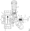
- the nozzle body designed as a multiple nozzle body according to the prior art Fig. 1 is intended to be arranged on the distributor rod of an agricultural crop protection sprayer and has a housing 1.
- the fastening means 2 is arranged on the housing 1, with which the multiple nozzle body can be fastened to frame elements, distributor rods, etc.
- In the upper area of the housing 1 of the multiple nozzle body is a section 3 of the liquid line, which is part of the housing 1.
- This section 3 is connected to, for example, the liquid line, which is designed as a feed line and is connected to the individual multiple nozzle bodies, which are arranged at a distance from one another on the distributor linkage. In this case, part 3 thus forms part of the liquid line.
- the liquid to be dispensed is fed to each multiple nozzle body via this liquid line 3.
- the discharge line 5 branches off in the branch area 4 from the section 3 of the liquid line.
- the discharge nozzle 8 is arranged at the end 6 of the discharge line 5 by means of a coupling piece 7.
- a dispensing and / or shut-off valve 9 with an electromotive actuating element 10, preferably a pulse width modulation valve, is arranged in the discharge line 5.
- a filter and / or sieve element 12 is arranged in the discharge line 5 in the area 11 between the shut-off valve 9 and the discharge nozzle 8.
- the supply of the liquid to be dispensed to the dispensing nozzle 8 can be shut off, or, if the valve 9 with the electromotive actuating element 10 is designed as a pulse width modulation valve, also additionally in the quantity of actually dispensed Regulate the liquid in a known manner.
- the valve 9 with the electromotive actuating element 10 is designed as a pulse width modulation valve, also additionally in the quantity of actually dispensed Regulate the liquid in a known manner.
- the discharge nozzle 8 due to the Arrangement of the filter and / or sieve element 12 in the area 11 between the shut-off valve 9 and the discharge nozzle 8 is arranged at a greater distance from the valve 9, so that the known multiple nozzle body a relatively large length from the section 3 of the liquid line designed as a feed line up to the lower end of the discharge nozzle 8.
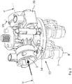
- the nozzle body 13 designed as a multiple nozzle body according to the invention according to FIGS Fig. 2 to 8 is also provided for arrangement on the distributor rod of an agricultural crop protection sprayer and has a housing 14.
- This multiple nozzle body 13 according to the invention differs from the multiple nozzle body 13 by a much more compact design Fig. 1 This is seen above all by the assignment of the at least one filter and / or sieve element 15 in the flow direction 16 of the liquid to be dispensed before the metering and / or shut-off element 17 in the dispensing line 18.
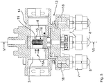
- Fig. 2 to 8 branch off two feed lines 18 from the feed line 3. At least one filter and / or sieve element 15 is arranged in the branch area 19 of the respective discharge line 18 from the feed line 3. Furthermore, at least one metering and / or shut-off valve 17 with an electromotive 20, preferably a pulse width modulation valve is arranged in each discharge line 18.
- the arrangement described above means that at least one filter and / or sieve element 15 is seen in the flow direction 21 of the liquid to be dispensed in front of the metering and / or shut-off element 17 in the branch area 4 of the dispensing line 18 from the supply line 3.
- the arrangement of the respective filter and / or sieve element 15 is such that it is arranged at least partially in the liquid flow 16 A flowing through the feed line 3 in the feed line 3.
- the filter and / or sieve element 15 is thus at least partially arranged in the liquid stream 16 A flowing through the feed line 15 in the feed line 3.
- the at least one filter and / or sieve element 15, viewed in the flow direction 16 or 16 A of the liquid to be dispensed is at least partially arranged in the feed line 3 in front of the metering and / or shut-off element 17.
- the discharge line 3 branches off from the supply line 3 in the upper region 22 of the supply line 3.
- the branching area 18 A of the discharge line 18 is initially aligned in the upper area 22 of the feed line 3, branching upward from the feed line 3.
- the application line 18 is U-shaped from the branch from the supply line 3 to the metering and / or shut-off element 17 in the application line 18.
- the dosing and / or shut-off element 17 is arranged in the at least approximately perpendicular region 18 B of the discharge line 18 in front of the nozzle 8.
- the discharge nozzles 8 compared to the known multiple nozzle body according to Fig. 1 be arranged much closer to the feed line 3, so that a much more compact design of the multiple nozzle body can be realized.
- the liquid to be discharged flowing in the feed line 3 branches off at least partially in the upper region 22 of the feed line in a partial flow 21 A in the branching region 18 A of the discharge line 18 through the filter and / or sieve element 15.
- This partial flow 21 A then flows further through the discharge line 18 to the metering and / or shut-off element 17 which is actuated by the electromotive actuating element 10 and which therefore acts as Pulse width modulation valve is formed.
- Pulse width modulation valve By means of this pulse width modulation valve, the application quantity of the liquid to be applied is determined in a known manner via which this 8.
- the above-described arrangement and orientation of the delivery line 18 in a U shape ensures that they have only a short length starting from the filter and / or sieve elements 15 up to the pulse width modulation valve 17. As a result, only a small volume of liquid can remain when switched off, so that the risk of flocculation of the liquid to be dispensed is significantly reduced in this area.
Landscapes
- Life Sciences & Earth Sciences (AREA)
- Engineering & Computer Science (AREA)
- Insects & Arthropods (AREA)
- Pest Control & Pesticides (AREA)
- Wood Science & Technology (AREA)
- Zoology (AREA)
- Environmental Sciences (AREA)
- Catching Or Destruction (AREA)
Abstract
Description
- Die Erfindung betrifft einen Düsenkörper für eine landwirtschaftliche Pflanzenschutzspritze gemäß dem Oberbegriff des Patentanspruches 1.
- Derartige Düsenkörper sind für landwirtschaftliche Pflanzenschutzspritzen in der Praxis bekannt geworden.
- Solche Düsenkörper, wie in
Fig.1 dargestellt, weisen ein Gehäuse mit zumindest einer Zuleitung auf. Von der Zuleitung zweigt zumindest eine zu zumindest einem an dem Gehäuse des Düsenkörpers angeordnete Düse abzweigende Ausbringleitung ab. In der Ausbringleitung ist zumindest ein Filter- und/oder Siebelement und zumindest ein Dosier- und/oder Absperrventil mit elektromotorischem Betätigungselement, vorzugsweise ein Pulsweitenmodulationsventil angeordnet. Das Filter- und/oder Siebelement ist zwischen dem von einem elektromotorischen Betätigungselement betätigten Dosier- und/oder Absperrventil, welche beispielsweise als Pulsweitenmodulationsventil ausgebildet sind, und der die auszubringenden Flüssigkeiten zerstäubenden Düse angeordnet. - Hierdurch gelangen in der auszubringenden Flüssigkeit enthaltenen Verunreinigungen direkt zu dem vor dem Filter- und/oder Siebelement angeordneten Dosier- und/oder Absperrventil. Diese in der auszubringenden Flüssigkeit enthaltenen Verunreinigungen verstopfen dann das jeweilige Filter- und/oder Siebelement. Darüber hinaus können die jeweiligen Filter- und/oder Siebelemente bei geschlossenen Dosier- und/oder Absperrventil nicht gespült oder umspült werden, so dass die Filter- und/oder Siebelemente in diesem Falle nicht gereinigt werden können oder die in der auszubringenden Flüssigkeit enthaltene Verunreinigungen und/oder Wirkstoffe aus der Trägerflüssigkeit der auszubringenden Flüssigkeit ausflocken und es so anschließend zu einer größeren Verstopfungsgefahr kommt. Dies beruht auch darauf, dass durch die bekannte Anordnung ein sehr großes Volumen bei abgesperrten Dosier- und/oder Absperrventil nicht in Bewegung gehalten wird, so dass es zwangsläufig zu den vorgenannten Problemen kommt. Außerdem baut der Düsenkörper im Bereich der Düse durch die Anordnung des Filter- und/oder Siebelementes zwischen dem Dosier- und/oder Absperrventil und der Düse sehr lang.
- Weiterhin ist bei der bekannten Anordnung nach
Fig.1 , bei welcher die Ausbringleitung in dem unteren Bereich der Zuleitung in Richtung des jeweiligen Dosier- und/oder Absperrventils vor dem jeweiligen Filter- und/oder Siebelement nach unten abzweigt, nachteilig, dass in diesem aufrecht verlaufenden Bereich der Ausbringleitung bei längerer Absperrung der Ausbringleitung durch das jeweilige Dosier- und/oder Absperrventil sich Auswirkungen in der auszubringenden Flüssigkeit bilden, so dass sowohl das jeweilige Filter- und/oder Siebelement wie auch die zugeordnete Ausbringdüse sehr schnell verstopfen und es so Arbeitsausfällen kommt. Auch ist die einwandfreie Funktion des jeweiligen Dosier- und/oder Absperrventils nicht gewährleistet. - Der Erfindung liegt die Aufgabe zu Grunde, in einfacher Weise bei einer kompakteren Bauweise des Düsenkörpers die Verstopfungsgefahr des Düsenkörpers, insbesondere im Bereich des jeweiligen Dosier- und/oder Absperrventils durch das jeweilige Filter- und/oder Siebelement zu vermeiden bzw. erheblich zu verringern.
- Diese Aufgabe der erfindungsgemäß dadurch gelöst, dass das zumindest eine Filter- und/oder Siebelement in Strömungsrichtung der auszubringenden Flüssigkeit gesehen vor dem Dosier- und/oder Absperrelement der Ausbringleitung zugeordnet ist.
- Infolge dieser Maßnahme wird durch die erfindungsgemäße Anordnung des jeweiligen Filter- und/oder Siebelementes einerseits erreicht, dass zumindest die gröberen Partikel von Verunreinigungen in der auszubringenden Flüssigkeit vor dem jeweiligen Filter- und/oder Siebelement aufgehalten werden, so dass sie nicht zu dem jeweiligen Dosier- und/oder Absperrelement gelangen. Somit wird eine Fehlfunktion des jeweiligen Dosier- und/oder Absperrelementes sicher verhindert. Außerdem wird durch diese Anordnung erreicht, dass bei geschlossenem Dosier- und/oder Absperrelement das jeweilige Dosier- und/oder Absperrelement permanent umspült wird, so dass eine Verstopfung vermieden werden kann.
- Außerdem wird durch diese integrierte Anordnung des jeweiligen jeweiligen Filter- und/oder Siebelementes vor dem jeweiligen Dosier- und/oder Absperrelement eine kompakte Bauweise des Düsenkörpers erreicht. Hierdurch lässt sich die Düse, welche die auszubringende Flüssigkeit zerstäubt, unmittelbar hinter dem jeweiligen Dosier- und/oder Absperrelement zur Erreichung der kompakten Bauweise mit einer reduzierten Länge des Düsenanschlussstutzens anordnen.
- In einer Weiterbildung der Erfindung ist vorgesehen, dass das zumindest eine Filter- und/oder Siebelement in Strömungsrichtung der auszubringenden Flüssigkeit gesehen vor dem Dosier- und/oder Absperrelement in der Ausbringleitung angeordnet ist. Hierdurch wird sichergestellt, dass bei einer integrierten Anordnung des Filter- und/oder Siebelementes dieses bei abgesperrten Dosier- und/oder Absperrelement ausreichend umspült bzw. durchspült wird.
- Eine besonders für die Durchspülung vorteilhafte Anordnung für das Filter- und/oder Siebelement ergibt sich dadurch, dass das zumindest eine Filter- und/oder Siebelement in Strömungsrichtung der auszubringenden Flüssigkeit gesehen vor dem Dosier- und/oder Absperrelement im Abzweigbereich der Ausbringleitung von der Zuleitung angeordnet ist.
- In einer bevorzugten Ausgestaltung ist vorgesehen, dass das zumindest eine Filter- und/oder Siebelement in Strömungsrichtung der auszubringenden Flüssigkeit gesehen vor dem Dosier- und/oder Absperrelement in der Zuleitung unmittelbar vor und/oder im Abzweigbereich der Ausbringleitung von der Zuleitung angeordnet ist.
- Um eine besonders gute Durchspülung und/oder Umspülung des Filter- und/oder Siebelementes zu erreichen, ist vorgesehen, dass das zumindest eine Filter- und/oder Siebelement zumindest teilweise in den durch die Zuleitung fließenden Flüssigkeitsstrom hineinragend in der Zuleitung angeordnet ist.
- Diese besonders gute Durchspülung und/oder Umspülung des Filter- und/oder Siebelementes lässt sich dadurch sicherstellen, dass das zumindest eine Filter- und/oder Siebelement zumindest teilweise in den durch die Zuleitung fließenden Flüssigkeitsstrom sich befindend in der Zuleitung angeordnet ist.
- Hierbei hat sich für die vorbeschriebene Wirkungsweise besonders vorteilhaft herausgestellt, dass die Ausbringleitung im oberen Bereich der Zuleitung zunächst nach oben gerichtet von der Zuleitung abzweigt.
- Eine vorteilhafte Führung der Ausbringleitung von der Zuleitung zu der Ausbringdüse mit den vorbeschriebenen Vorteilen wird dadurch erreicht, dass die Ausbringleitung von der Abzweigung von der Zuleitung U-förmig bis zu dem Dosier- und/oder Absperrelement in der Ausbringleitung verlaufend ausgebildet ist.
- Eine vorteilhafte Anordnung für das das Dosier- und/oder Absperrelement ergibt sich dadurch, dass das Dosier- und/oder Absperrelement in dem zumindest annähernd senkrecht verlaufenden Bereich der Ausbringleitung vor der Düse angeordnet ist.
- Weitere Einzelheiten der Erfindung sind der Beispielsbeschreibung und den Zeichnungen zu entnehmen. Die Zeichnungen zeigen
- Fig.1
- einen Düsenkörper nach dem Stand der Technik im Längsschnitt,
- Fig.2
- einen erfindungsgemäßen Düsenkörper in perspektivischer Darstellung,
- Fig.3
- den erfindungsgemäßen Düsenkörper nach
Fig.2 in Seitenansicht, - Fig.4
- den erfindungsgemäßen Düsenkörper nach
Fig.2 im Schnitt IV - IV, - Fig.5
- den erfindungsgemäßen Düsenkörper nach
Fig.2 im Längsschnitt V - V, - Fig.6
- den erfindungsgemäßen Düsenkörper nach
Fig.2 im Querschnitt VI - VI, - Fig.7
- den erfindungsgemäßen Düsenkörper nach
Fig.2 im Schnitt VII - VII und - Fig.8
- den erfindungsgemäßen Düsenkörper nach
Fig.2 im Schnitt VIII - VIII. - Der als Mehrfachdüsenkörper entsprechend des Standes der Technik ausgebildete Düsenkörper gemäß
Fig.1 ist zur Anordnung an dem Verteilergestänge einer landwirtschaftlichen Pflanzenschutzspritze vorgesehen und weist ein Gehäuse 1 auf. An dem Gehäuse 1 ist die Befestigungsmittel 2 angeordnet, mit welchem der Mehrfachdüsenkörper an Rahmenelementen, Verteilergestänge, etc. befestigt werden kann. Im oberen Bereich des Gehäuses 1 des Mehrfachdüsenkörpers befindet sich ein Teilstück 3 der Flüssigkeitsleitung, welches Bestandteil des Gehäuses 1 ist. Dieses Teilstück 3 wird an die beispielsweise im Verteilergestänge verlegte als Zuleitung ausgebildete Flüssigkeitsleitung, an die einzelnen Mehrfachdüsenkörper, die beabstandet zueinander an dem Verteilergestänge angeordnet sind, angeschlossen sind. Somit bildet in diesem Falle das Teilstück 3 ein Teil der Flüssigkeitsleitung. Über diese Flüssigkeitsleitung 3 wird jeden Mehrfachdüsenkörper die auszubringende Flüssigkeit zugeführt. - Von dem Teilstück 3 der Flüssigkeitsleitung zweigt im Abzweigbereich 4 die Ausbringleitung 5 ab. An dem Ende 6 der Ausbringleitung 5 ist mittels eines Kuppelstückes 7 die Ausbringdüse 8 angeordnet. In der Ausbringleitung 5 ist ein Dosier- und/oder Absperrventil 9 mit elektromotorischem Betätigungselement 10, vorzugsweise ein Pulsweitenmodulationsventil angeordnet. Weiterhin ist in der Ausbringleitung 5 in dem Bereich 11 zwischen dem Absperrventil 9 und der Ausbringdüse 8 ein Filter- und/oder Siebelement 12 angeordnet. Mittels des Filter- und/oder Siebelementes 12 werden Verunreinigungen in der auszubringenden Flüssigkeit, die durch die Ausbringdüse 8 zerstäubt wird, von der Ausbringdüse ferngehalten, so dass diese nicht verstopft. Mittels des Dosier- und/oder Absperrventils 9 mit elektromotorischem Betätigungselement 10 lässt sich die Zufuhr der auszubringenden Flüssigkeit zu der Ausbringdüse 8 absperren, oder wenn das Ventil 9 mit dem elektromotorischem Betätigungselement 10 als Pulsweitenmodulationsventil ausgebildet ist, auch zusätzlich in der tatsächlich ausgebrachten Menge an auszubringender Flüssigkeit in bekannter Weise regulieren. Wie in der
Fig.1 erkennbar ist, ist die Ausbringdüse 8 aufgrund der Anordnung des Filter- und/oder Siebelementes 12 in dem Bereich 11 zwischen dem Absperrventil 9 und der Ausbringdüse 8 in einem größeren Abstand von dem Ventil 9 entfernt angeordnet, so dass der bekannte Mehrfachdüsenkörper eine relativ große Länge von dem Teilstück 3 der als Zuleitung ausgebildete Flüssigkeitsleitung bis zu dem unteren Ende der Ausbringdüse 8 aufweist. - Der als Mehrfachdüsenkörper nach der Erfindung ausgebildete Düsenkörper 13 gemäß den
Fig.2 bis 8 ist ebenfalls zur Anordnung an dem Verteilergestänge einer landwirtschaftlichen Pflanzenschutzspritze vorgesehen und weist ein Gehäuse 14 auf. Dieser erfindungsgemäße Mehrfachdüsenkörper 13 unterscheidet sich durch eine wesentlich kompaktere Bauweise von dem Mehrfachdüsenkörper 13 nachFig.1 , dies wird vor allem durch die Zuordnung des zumindest einen Filter- und/oder Siebelementes 15 in Strömungsrichtung 16 der auszubringenden Flüssigkeit gesehen vordem Dosier- und/oder Absperrelement 17 in der Ausbringleitung 18. - Bei dem erfindungsgemäßen Düsenkörper nach den
Fig.2 bis 8 zweigen von der Zuleitung 3 zwei Ausbringleitungen 18 ab. In dem Abzweigbereich 19 der jeweiligen Ausbringleitung 18 von der Zuleitung 3 ist jeweils zumindest ein Filter- und/oder Siebelement 15 angeordnet. Weiterhin ist in jeder Ausbringleitung 18 zumindest ein Dosier- und/oder Absperrventil 17 mit elektromotorischem 20, vorzugsweise ein Pulsweitenmodulationsventil angeordnet. - Das zumindest eine Filter- und/oder Siebelement 15 ist in Strömungsrichtung 21 der auszubringenden Flüssigkeit gesehen vor dem Dosier- und/oder Absperrelement 17 in der Ausbringleitung 18 angeordnet. Durch die vorbeschriebene Anordnung ist das jeweils zumindest eine Filter- und/oder Siebelement 15 in Strömungsrichtung 21 der auszubringenden Flüssigkeit gesehen vor dem Dosier- und/oder Absperrelement 17 im Abzweigbereich 4 der Ausbringleitung 18 von der Zuleitung 3. Hierbei ist das zumindest eine Filter- und/oder Siebelement 15 in Strömungsrichtung 21 der auszubringenden Flüssigkeit gesehen vor dem Dosier- und/oder Absperrelement 17 in der Zuleitung 3 unmittelbar vor und/oder im Abzweigbereich 4 der Ausbringleitung 18 von der Zuleitung 3 angeordnet.
- Die Anordnung des jeweiligen Filter- und/oder Siebelementes 15 ist so vorgenommen, dass es zumindest teilweise in den durch die Zuleitung 3 fließenden Flüssigkeitsstrom 16 A hineinragend in der Zuleitung 3 angeordnet ist. Somit befindet sich das Filter- und/oder Siebelement 15 zumindest teilweise in den durch die Zuleitung 15 fließenden Flüssigkeitsstrom 16 A in der Zuleitung 3 angeordnet. Um dieses sicher zu erreichen ist das zumindest eine Filter- und/oder Siebelement 15 in Strömungsrichtung 16 bzw. 16 A der auszubringenden Flüssigkeit gesehen vor dem Dosier- und/oder Absperrelement 17 zumindest teilweise in der Zuleitung 3 angeordnet. Hierbei zweigt die Ausbringleitung 3 im oberen Bereich 22 der Zuleitung 3 von der Zuleitung 3 ab.
- Der abzweigende Bereich 18 A der Ausbringleitung 18 ist im oberen Bereich 22 der Zuleitung 3 zunächst nach oben von der Zuleitung 3 abzweigend ausgerichtet. Die Ausbringleitung 18 ist von der Abzweigung von der Zuleitung 3 U-förmig bis zu dem Dosier- und/oder Absperrelement 17 in der Ausbringleitung 18 verlaufend ausgebildet. Das Dosier- und/oder Absperrelement 17 ist in dem zumindest annähernd senkrecht verlaufenden Bereich 18 B der Ausbringleitung 18 vor der Düse 8 angeordnet ist.
- Wie aus den Zeichnungen gemäß den
Fig.2 bis 8 ersichtlich ist, können die Ausbringdüsen 8 gegenüber dem bekannten Mehrfachdüsenkörper gemäßFig.1 wesentlich dichter zu der Zuleitung 3 angeordnet werden, so dass sich eine wesentlich kompaktere Ausgestaltung des Mehrfachdüsenkörpers realisieren lässt. - Die Funktionsweise ist folgende:
Die in der Zuleitung 3 strömende auszubringende Flüssigkeit zweigt zumindest teilweise in dem oberen Bereich 22 der Zuleitung in einem Teilstrom 21 A in dem abzweigenden Bereich 18 A der Ausbringleitung 18 durch das Filter- und/oder Siebelement 15 ab. Dieser Teilstrom 21 A strömt dann weiter durch die Ausbringleitung 18 zu dem von dem elektromotorischen Betätigungselement 10 betätigten Dosier- und/oder Absperrelement 17, welches somit als Pulsweitenmodulationsventil ausgebildet ist. Durch dieses Pulsweitenmodulationsventil wird in bekannter Weise die Ausbringmenge der auszubringenden Flüssigkeit über die diese 8 bestimmt. - Durch die in die Flüssigkeitsströmung 16 und 16 A in der Zuleitung 3 hineinragende Anordnung der Filter- und/oder Siebelemente 15 liegen diese Filter- und/oder Siebelement 15 zumindest teilweise in den Flüssigkeitsstrom der Zuleitung 3. Hierdurch ist die vorbeschriebene Reinigung der Filter- und/oder Siebelemente 15 und Vermeidung von Ablagerungen in und/oder an den Filter- und/oder Siebelemente 15 sichergestellt. Hierdurch wird die Verstopfungsgefahr von dem elektromotorischen Betätigungselement 10 betätigten Dosier- und/oder Absperrelement 17 erheblich reduziert, so dass insbesondere bei der Ausgestaltung als Pulsweitenmodulationsventile eine einwandfreie Funktion des Ventils gewährleistet ist.
- Durch die vorbeschriebene Anordnung und Ausrichtung der Ausbringleitung 18 in U-Form wird sichergestellt, dass diese von den Filter- und/oder Siebelementen 15 ausgehend bis zu dem Pulsweitenmodulationsventil 17 nur eine geringe Länge aufweisen. Hierdurch kann nur ein geringes Flüssigkeitsvolumen bei Abschaltung stehen bleiben, so dass die Ausflockungsgefahr der auszubringenden Flüssigkeit in diesem Bereich deutlich reduziert ist.
Claims (10)
- Düsenkörper (13) für eine landwirtschaftliche Pflanzenschutzspritze, wobei der Düsenkörper ein Gehäuse (14) mit zumindest einer Zuleitung (3) aufweist, wobei von der Zuleitung (3) zumindest eine zu zumindest einem an dem Gehäuse (14) des Düsenkörpers (13) angeordnete Düse (8) abzweigende Ausbringleitung (18) abzweigt, wobei in der Ausbringleitung (18) zumindest ein Filter- und/oder Siebelement (15) und zumindest ein Dosier- und/oder Absperrventil (17) mit elektromotorischem Betätigungselement (20), vorzugsweise ein Pulsweitenmodulationsventil angeordnet ist, dadurch gekennzeichnet, dass das zumindest eine Filter- und/oder Siebelement (15) in Strömungsrichtung (16, 16A) der auszubringenden Flüssigkeit gesehen vor dem Dosier- und/oder Absperrelement (17) der Ausbringleitung (18) zugeordnet ist.
- Düsenkörper nach Anspruch 1, dadurch gekennzeichnet, dass das zumindest eine Filter- und/oder Siebelement (15) in Strömungsrichtung (16, 16A) der auszubringenden Flüssigkeit gesehen vor dem Dosier- und/oder Absperrelement (17) in der Ausbringleitung (18) angeordnet ist.
- Düsenkörper nach zumindest einem der vorstehenden Ansprüche, dadurch gekennzeichnet, dass das zumindest eine Filter- und/oder Siebelement (17) in Strömungsrichtung (16, 16A) der auszubringenden Flüssigkeit gesehen vordem Dosier- und/oder Absperrelement (17) im Abzweigbereich (19) der Ausbringleitung (18) von der Zuleitung (3) angeordnet ist.
- Düsenkörper nach zumindest einem der Ansprüche 1 bis 2, dadurch gekennzeichnet, dass das zumindest eine Filter- und/oder Siebelement (15) in Strömungsrichtung (16, 16A) der auszubringenden Flüssigkeit gesehen vor dem Dosier- und/oder Absperrelement (17) in der Zuleitung (3) unmittelbar vor und/oder im Abzweigbereich (19) der Ausbringleitung (18) von der Zuleitung (3) angeordnet ist.
- Düsenkörper nach zumindest einem der vorstehenden Ansprüche, dadurch gekennzeichnet, dass das zumindest eine Filter- und/oder Siebelement (15) zumindest teilweise in den durch die Zuleitung (3) fließenden Flüssigkeitsstrom (16, 16A) hineinragend in der Zuleitung (3) angeordnet ist.
- Düsenkörper nach zumindest einem der vorstehenden Ansprüche, dadurch gekennzeichnet, dass das zumindest eine Filter- und/oder Siebelement (15) zumindest teilweise in den durch die Zuleitung (3) fließenden Flüssigkeitsstrom (16, 16A) sich befindend in der Zuleitung (3) angeordnet ist.
- Düsenkörper nach zumindest einem der vorstehenden Ansprüche, dadurch gekennzeichnet, dass die Ausbringleitung (18) im oberen Bereich (22) der Zuleitung (3) von der Zuleitung (3) abzweigt.
- Düsenkörper nach zumindest einem der vorstehenden Ansprüche, dadurch gekennzeichnet, dass die Ausbringleitung (18) im oberen Bereich (22) der Zuleitung (3) zunächst nach oben gerichtet von der Zuleitung (3) abzweigt.
- Düsenkörper nach zumindest einem der vorstehenden Ansprüche, dadurch gekennzeichnet, dass die Ausbringleitung (18) von der Abzweigung von der Zuleitung (3) U-förmig bis zu dem Dosier- und/oder Absperrelement (17) in der Ausbringleitung (18) verlaufend ausgebildet ist
- Düsenkörper nach zumindest einem der vorstehenden Ansprüche, dadurch gekennzeichnet, dass das Dosier- und/oder Absperrelement (17) in dem zumindest annähernd senkrecht verlaufenden Bereich (18B) der Ausbringleitung (17) vor der Düse (8) angeordnet ist.
Priority Applications (1)
| Application Number | Priority Date | Filing Date | Title |
|---|---|---|---|
| PL19401039T PL3643410T3 (pl) | 2018-10-25 | 2019-09-30 | Korpus rozpylacza opryskiwacza rolniczego do ochrony roślin |
Applications Claiming Priority (2)
| Application Number | Priority Date | Filing Date | Title |
|---|---|---|---|
| DE102018126580.8A DE102018126580A1 (de) | 2018-10-25 | 2018-10-25 | Düsenkörper für eine landwirtschaftliche Pflanzenschutzspritze |
| DE102018126578.6A DE102018126578A1 (de) | 2018-10-25 | 2018-10-25 | Düsenkörper für eine landwirtschaftliche Pflanzenschutzspritze |
Publications (2)
| Publication Number | Publication Date |
|---|---|
| EP3643410A1 true EP3643410A1 (de) | 2020-04-29 |
| EP3643410B1 EP3643410B1 (de) | 2021-06-02 |
Family
ID=68242620
Family Applications (1)
| Application Number | Title | Priority Date | Filing Date |
|---|---|---|---|
| EP19401039.3A Active EP3643410B1 (de) | 2018-10-25 | 2019-09-30 | Düsenkörper für eine landwirtschaftliche pflanzenschutzspritze |
Country Status (3)
| Country | Link |
|---|---|
| EP (1) | EP3643410B1 (de) |
| DK (1) | DK3643410T3 (de) |
| PL (1) | PL3643410T3 (de) |
Citations (2)
| Publication number | Priority date | Publication date | Assignee | Title |
|---|---|---|---|---|
| US8888015B2 (en) * | 2008-11-19 | 2014-11-18 | Richard D. Rayner | Spray bar and filter apparatus |
| EP3533523A1 (de) * | 2018-03-01 | 2019-09-04 | Amazonen-Werke H. Dreyer GmbH & Co. KG | Düsenanordnung für eine feldspritze |
-
2019
- 2019-09-30 EP EP19401039.3A patent/EP3643410B1/de active Active
- 2019-09-30 DK DK19401039.3T patent/DK3643410T3/da active
- 2019-09-30 PL PL19401039T patent/PL3643410T3/pl unknown
Patent Citations (3)
| Publication number | Priority date | Publication date | Assignee | Title |
|---|---|---|---|---|
| US8888015B2 (en) * | 2008-11-19 | 2014-11-18 | Richard D. Rayner | Spray bar and filter apparatus |
| EP3533523A1 (de) * | 2018-03-01 | 2019-09-04 | Amazonen-Werke H. Dreyer GmbH & Co. KG | Düsenanordnung für eine feldspritze |
| DE102018104689A1 (de) * | 2018-03-01 | 2019-09-05 | Amazonen-Werke H. Dreyer Gmbh & Co. Kg | Düsenanordnung für eine Feldspritze |
Also Published As
| Publication number | Publication date |
|---|---|
| PL3643410T3 (pl) | 2021-12-20 |
| EP3643410B1 (de) | 2021-06-02 |
| DK3643410T3 (da) | 2021-08-16 |
Similar Documents
| Publication | Publication Date | Title |
|---|---|---|
| EP0799560A2 (de) | Abluftleitung für eine pneumatisch arbeitende Verteilmaschine | |
| EP3706568A1 (de) | Spritzeinrichtung und verfahren | |
| EP0385926B1 (de) | Vorrichtung zum Ausbringen von Pflanzenschutzmitteln | |
| DE102011050207A1 (de) | Landwirtschaftliche Feldspritze | |
| EP1825749A1 (de) | Landwirtschaftliche Feldspritze | |
| EP3114930B1 (de) | Spritzsystem | |
| EP3645170A1 (de) | Abgabeeinheit zur abgabe einer endflüssigkeit mit einem definierten endmischverhältnis | |
| EP2084964A1 (de) | Spritzeinrichtung | |
| DE102006059193A1 (de) | Spritzeinrichtung | |
| EP3643410B1 (de) | Düsenkörper für eine landwirtschaftliche pflanzenschutzspritze | |
| DE102018126580A1 (de) | Düsenkörper für eine landwirtschaftliche Pflanzenschutzspritze | |
| DE102018126578A1 (de) | Düsenkörper für eine landwirtschaftliche Pflanzenschutzspritze | |
| EP3225111B1 (de) | Einspülbehälter mit einspüldüsen | |
| DE102006059194A1 (de) | Spritzeinrichtung | |
| DE202016101158U1 (de) | Vorrichtung zum Ausbringen einer Flüssigkeit | |
| DE102007017315A1 (de) | Spritzeinrichtung eines Spritzgestänges | |
| DE202018104133U1 (de) | Vorrichtung zum Einbringen einer Flüssigkeit in einen Boden | |
| DE202006010074U1 (de) | Landwirtschaftliche Feldspritze | |
| DE4441472A1 (de) | Feldspritze | |
| EP2832222B1 (de) | Landwirtschaftliche Feldspritze | |
| DE102024207226A1 (de) | Reinigungsvorrichtung für einen Sensor | |
| DE3145113C2 (de) | Tankwagen zum Aufbringen von insbesondere Gülle auf landwirtschaftlich genutzte Bodenflächen | |
| DE102005062535A1 (de) | Vorrichtung zum Versprühen von flüssigen Gemischen | |
| DE102008006888A1 (de) | Spritzeinrichtung | |
| DE102011001967A1 (de) | Landwirtschaftliche Feldspritze |
Legal Events
| Date | Code | Title | Description |
|---|---|---|---|
| PUAI | Public reference made under article 153(3) epc to a published international application that has entered the european phase |
Free format text: ORIGINAL CODE: 0009012 |
|
| STAA | Information on the status of an ep patent application or granted ep patent |
Free format text: STATUS: THE APPLICATION HAS BEEN PUBLISHED |
|
| AK | Designated contracting states |
Kind code of ref document: A1 Designated state(s): AL AT BE BG CH CY CZ DE DK EE ES FI FR GB GR HR HU IE IS IT LI LT LU LV MC MK MT NL NO PL PT RO RS SE SI SK SM TR |
|
| AX | Request for extension of the european patent |
Extension state: BA ME |
|
| STAA | Information on the status of an ep patent application or granted ep patent |
Free format text: STATUS: REQUEST FOR EXAMINATION WAS MADE |
|
| 17P | Request for examination filed |
Effective date: 20200908 |
|
| RBV | Designated contracting states (corrected) |
Designated state(s): AL AT BE BG CH CY CZ DE DK EE ES FI FR GB GR HR HU IE IS IT LI LT LU LV MC MK MT NL NO PL PT RO RS SE SI SK SM TR |
|
| GRAP | Despatch of communication of intention to grant a patent |
Free format text: ORIGINAL CODE: EPIDOSNIGR1 |
|
| STAA | Information on the status of an ep patent application or granted ep patent |
Free format text: STATUS: GRANT OF PATENT IS INTENDED |
|
| RIC1 | Information provided on ipc code assigned before grant |
Ipc: B05B 15/40 20180101AFI20210203BHEP Ipc: B05B 1/30 20060101ALN20210203BHEP Ipc: B05B 1/16 20060101ALN20210203BHEP Ipc: B05B 15/658 20180101ALN20210203BHEP Ipc: A01M 7/00 20060101ALI20210203BHEP |
|
| INTG | Intention to grant announced |
Effective date: 20210301 |
|
| RIC1 | Information provided on ipc code assigned before grant |
Ipc: B05B 1/16 20060101ALN20210219BHEP Ipc: B05B 15/658 20180101ALN20210219BHEP Ipc: B05B 15/40 20180101AFI20210219BHEP Ipc: B05B 1/30 20060101ALN20210219BHEP Ipc: A01M 7/00 20060101ALI20210219BHEP |
|
| GRAS | Grant fee paid |
Free format text: ORIGINAL CODE: EPIDOSNIGR3 |
|
| RAP3 | Party data changed (applicant data changed or rights of an application transferred) |
Owner name: AMAZONEN-WERK H. DREYER SE & CO. KG |
|
| GRAA | (expected) grant |
Free format text: ORIGINAL CODE: 0009210 |
|
| STAA | Information on the status of an ep patent application or granted ep patent |
Free format text: STATUS: THE PATENT HAS BEEN GRANTED |
|
| RAP3 | Party data changed (applicant data changed or rights of an application transferred) |
Owner name: AMAZONEN-WERKE H. DREYER SE & CO. KG |
|
| REG | Reference to a national code |
Ref country code: CH Ref legal event code: EP |
|
| AK | Designated contracting states |
Kind code of ref document: B1 Designated state(s): AL AT BE BG CH CY CZ DE DK EE ES FI FR GB GR HR HU IE IS IT LI LT LU LV MC MK MT NL NO PL PT RO RS SE SI SK SM TR |
|
| REG | Reference to a national code |
Ref country code: GB Ref legal event code: FG4D Free format text: NOT ENGLISH |
|
| REG | Reference to a national code |
Ref country code: AT Ref legal event code: REF Ref document number: 1397951 Country of ref document: AT Kind code of ref document: T Effective date: 20210615 |
|
| REG | Reference to a national code |
Ref country code: IE Ref legal event code: FG4D Free format text: LANGUAGE OF EP DOCUMENT: GERMAN |
|
| REG | Reference to a national code |
Ref country code: DE Ref legal event code: R096 Ref document number: 502019001544 Country of ref document: DE |
|
| REG | Reference to a national code |
Ref country code: DK Ref legal event code: T3 Effective date: 20210809 |
|
| REG | Reference to a national code |
Ref country code: NL Ref legal event code: FP |
|
| REG | Reference to a national code |
Ref country code: LT Ref legal event code: MG9D |
|
| PG25 | Lapsed in a contracting state [announced via postgrant information from national office to epo] |
Ref country code: FI Free format text: LAPSE BECAUSE OF FAILURE TO SUBMIT A TRANSLATION OF THE DESCRIPTION OR TO PAY THE FEE WITHIN THE PRESCRIBED TIME-LIMIT Effective date: 20210602 Ref country code: HR Free format text: LAPSE BECAUSE OF FAILURE TO SUBMIT A TRANSLATION OF THE DESCRIPTION OR TO PAY THE FEE WITHIN THE PRESCRIBED TIME-LIMIT Effective date: 20210602 Ref country code: LT Free format text: LAPSE BECAUSE OF FAILURE TO SUBMIT A TRANSLATION OF THE DESCRIPTION OR TO PAY THE FEE WITHIN THE PRESCRIBED TIME-LIMIT Effective date: 20210602 Ref country code: BG Free format text: LAPSE BECAUSE OF FAILURE TO SUBMIT A TRANSLATION OF THE DESCRIPTION OR TO PAY THE FEE WITHIN THE PRESCRIBED TIME-LIMIT Effective date: 20210902 |
|
| PG25 | Lapsed in a contracting state [announced via postgrant information from national office to epo] |
Ref country code: RS Free format text: LAPSE BECAUSE OF FAILURE TO SUBMIT A TRANSLATION OF THE DESCRIPTION OR TO PAY THE FEE WITHIN THE PRESCRIBED TIME-LIMIT Effective date: 20210602 Ref country code: SE Free format text: LAPSE BECAUSE OF FAILURE TO SUBMIT A TRANSLATION OF THE DESCRIPTION OR TO PAY THE FEE WITHIN THE PRESCRIBED TIME-LIMIT Effective date: 20210602 Ref country code: LV Free format text: LAPSE BECAUSE OF FAILURE TO SUBMIT A TRANSLATION OF THE DESCRIPTION OR TO PAY THE FEE WITHIN THE PRESCRIBED TIME-LIMIT Effective date: 20210602 Ref country code: NO Free format text: LAPSE BECAUSE OF FAILURE TO SUBMIT A TRANSLATION OF THE DESCRIPTION OR TO PAY THE FEE WITHIN THE PRESCRIBED TIME-LIMIT Effective date: 20210902 Ref country code: GR Free format text: LAPSE BECAUSE OF FAILURE TO SUBMIT A TRANSLATION OF THE DESCRIPTION OR TO PAY THE FEE WITHIN THE PRESCRIBED TIME-LIMIT Effective date: 20210903 |
|
| PG25 | Lapsed in a contracting state [announced via postgrant information from national office to epo] |
Ref country code: ES Free format text: LAPSE BECAUSE OF FAILURE TO SUBMIT A TRANSLATION OF THE DESCRIPTION OR TO PAY THE FEE WITHIN THE PRESCRIBED TIME-LIMIT Effective date: 20210602 Ref country code: EE Free format text: LAPSE BECAUSE OF FAILURE TO SUBMIT A TRANSLATION OF THE DESCRIPTION OR TO PAY THE FEE WITHIN THE PRESCRIBED TIME-LIMIT Effective date: 20210602 Ref country code: SK Free format text: LAPSE BECAUSE OF FAILURE TO SUBMIT A TRANSLATION OF THE DESCRIPTION OR TO PAY THE FEE WITHIN THE PRESCRIBED TIME-LIMIT Effective date: 20210602 Ref country code: SM Free format text: LAPSE BECAUSE OF FAILURE TO SUBMIT A TRANSLATION OF THE DESCRIPTION OR TO PAY THE FEE WITHIN THE PRESCRIBED TIME-LIMIT Effective date: 20210602 Ref country code: PT Free format text: LAPSE BECAUSE OF FAILURE TO SUBMIT A TRANSLATION OF THE DESCRIPTION OR TO PAY THE FEE WITHIN THE PRESCRIBED TIME-LIMIT Effective date: 20211004 Ref country code: RO Free format text: LAPSE BECAUSE OF FAILURE TO SUBMIT A TRANSLATION OF THE DESCRIPTION OR TO PAY THE FEE WITHIN THE PRESCRIBED TIME-LIMIT Effective date: 20210602 |
|
| REG | Reference to a national code |
Ref country code: DE Ref legal event code: R097 Ref document number: 502019001544 Country of ref document: DE |
|
| PLBE | No opposition filed within time limit |
Free format text: ORIGINAL CODE: 0009261 |
|
| STAA | Information on the status of an ep patent application or granted ep patent |
Free format text: STATUS: NO OPPOSITION FILED WITHIN TIME LIMIT |
|
| 26N | No opposition filed |
Effective date: 20220303 |
|
| REG | Reference to a national code |
Ref country code: BE Ref legal event code: MM Effective date: 20210930 |
|
| PG25 | Lapsed in a contracting state [announced via postgrant information from national office to epo] |
Ref country code: MC Free format text: LAPSE BECAUSE OF FAILURE TO SUBMIT A TRANSLATION OF THE DESCRIPTION OR TO PAY THE FEE WITHIN THE PRESCRIBED TIME-LIMIT Effective date: 20210602 Ref country code: AL Free format text: LAPSE BECAUSE OF FAILURE TO SUBMIT A TRANSLATION OF THE DESCRIPTION OR TO PAY THE FEE WITHIN THE PRESCRIBED TIME-LIMIT Effective date: 20210602 |
|
| PG25 | Lapsed in a contracting state [announced via postgrant information from national office to epo] |
Ref country code: LU Free format text: LAPSE BECAUSE OF NON-PAYMENT OF DUE FEES Effective date: 20210930 Ref country code: IT Free format text: LAPSE BECAUSE OF FAILURE TO SUBMIT A TRANSLATION OF THE DESCRIPTION OR TO PAY THE FEE WITHIN THE PRESCRIBED TIME-LIMIT Effective date: 20210602 Ref country code: IE Free format text: LAPSE BECAUSE OF NON-PAYMENT OF DUE FEES Effective date: 20210930 Ref country code: BE Free format text: LAPSE BECAUSE OF NON-PAYMENT OF DUE FEES Effective date: 20210930 |
|
| REG | Reference to a national code |
Ref country code: CH Ref legal event code: PL |
|
| P01 | Opt-out of the competence of the unified patent court (upc) registered |
Effective date: 20230523 |
|
| PG25 | Lapsed in a contracting state [announced via postgrant information from national office to epo] |
Ref country code: CY Free format text: LAPSE BECAUSE OF FAILURE TO SUBMIT A TRANSLATION OF THE DESCRIPTION OR TO PAY THE FEE WITHIN THE PRESCRIBED TIME-LIMIT Effective date: 20210602 |
|
| PG25 | Lapsed in a contracting state [announced via postgrant information from national office to epo] |
Ref country code: LI Free format text: LAPSE BECAUSE OF NON-PAYMENT OF DUE FEES Effective date: 20220930 Ref country code: HU Free format text: LAPSE BECAUSE OF FAILURE TO SUBMIT A TRANSLATION OF THE DESCRIPTION OR TO PAY THE FEE WITHIN THE PRESCRIBED TIME-LIMIT; INVALID AB INITIO Effective date: 20190930 Ref country code: CH Free format text: LAPSE BECAUSE OF NON-PAYMENT OF DUE FEES Effective date: 20220930 |
|
| PG25 | Lapsed in a contracting state [announced via postgrant information from national office to epo] |
Ref country code: MK Free format text: LAPSE BECAUSE OF FAILURE TO SUBMIT A TRANSLATION OF THE DESCRIPTION OR TO PAY THE FEE WITHIN THE PRESCRIBED TIME-LIMIT Effective date: 20210602 |
|
| GBPC | Gb: european patent ceased through non-payment of renewal fee |
Effective date: 20230930 |
|
| PG25 | Lapsed in a contracting state [announced via postgrant information from national office to epo] |
Ref country code: GB Free format text: LAPSE BECAUSE OF NON-PAYMENT OF DUE FEES Effective date: 20230930 |
|
| PG25 | Lapsed in a contracting state [announced via postgrant information from national office to epo] |
Ref country code: GB Free format text: LAPSE BECAUSE OF NON-PAYMENT OF DUE FEES Effective date: 20230930 |
|
| PG25 | Lapsed in a contracting state [announced via postgrant information from national office to epo] |
Ref country code: MT Free format text: LAPSE BECAUSE OF FAILURE TO SUBMIT A TRANSLATION OF THE DESCRIPTION OR TO PAY THE FEE WITHIN THE PRESCRIBED TIME-LIMIT Effective date: 20210602 |
|
| PGFP | Annual fee paid to national office [announced via postgrant information from national office to epo] |
Ref country code: NL Payment date: 20250704 Year of fee payment: 7 |
|
| PGFP | Annual fee paid to national office [announced via postgrant information from national office to epo] |
Ref country code: DK Payment date: 20250911 Year of fee payment: 7 Ref country code: DE Payment date: 20250805 Year of fee payment: 7 |
|
| PGFP | Annual fee paid to national office [announced via postgrant information from national office to epo] |
Ref country code: PL Payment date: 20250714 Year of fee payment: 7 |
|
| PGFP | Annual fee paid to national office [announced via postgrant information from national office to epo] |
Ref country code: FR Payment date: 20250808 Year of fee payment: 7 |
|
| PGFP | Annual fee paid to national office [announced via postgrant information from national office to epo] |
Ref country code: CZ Payment date: 20250923 Year of fee payment: 7 |
|
| REG | Reference to a national code |
Ref country code: AT Ref legal event code: MM01 Ref document number: 1397951 Country of ref document: AT Kind code of ref document: T Effective date: 20240930 |
|
| PG25 | Lapsed in a contracting state [announced via postgrant information from national office to epo] |
Ref country code: TR Free format text: LAPSE BECAUSE OF FAILURE TO SUBMIT A TRANSLATION OF THE DESCRIPTION OR TO PAY THE FEE WITHIN THE PRESCRIBED TIME-LIMIT Effective date: 20210602 |
|
| PG25 | Lapsed in a contracting state [announced via postgrant information from national office to epo] |
Ref country code: AT Free format text: LAPSE BECAUSE OF NON-PAYMENT OF DUE FEES Effective date: 20240930 |
|
| PGFP | Annual fee paid to national office [announced via postgrant information from national office to epo] |
Ref country code: AT Payment date: 20260410 Year of fee payment: 5 |