EP3642094B1 - Roll-rigid rail vehicle coupling - Google Patents
Roll-rigid rail vehicle coupling Download PDFInfo
- Publication number
- EP3642094B1 EP3642094B1 EP18785844.4A EP18785844A EP3642094B1 EP 3642094 B1 EP3642094 B1 EP 3642094B1 EP 18785844 A EP18785844 A EP 18785844A EP 3642094 B1 EP3642094 B1 EP 3642094B1
- Authority
- EP
- European Patent Office
- Prior art keywords
- rail vehicle
- coupling
- bracket
- vehicle coupling
- axle
- Prior art date
- Legal status (The legal status is an assumption and is not a legal conclusion. Google has not performed a legal analysis and makes no representation as to the accuracy of the status listed.)
- Active
Links
- 230000008878 coupling Effects 0.000 title claims description 41
- 238000010168 coupling process Methods 0.000 title claims description 41
- 238000005859 coupling reaction Methods 0.000 title claims description 41
- 238000010276 construction Methods 0.000 description 9
- 238000009434 installation Methods 0.000 description 2
- 238000005096 rolling process Methods 0.000 description 2
- 230000000903 blocking effect Effects 0.000 description 1
- 229920001971 elastomer Polymers 0.000 description 1
- 239000000806 elastomer Substances 0.000 description 1
Images

Classifications
-
- B—PERFORMING OPERATIONS; TRANSPORTING
- B61—RAILWAYS
- B61G—COUPLINGS; DRAUGHT AND BUFFING APPLIANCES
- B61G5/00—Couplings for special purposes not otherwise provided for
- B61G5/02—Couplings for special purposes not otherwise provided for for coupling articulated trains, locomotives and tenders or the bogies of a vehicle; Coupling by means of a single coupling bar; Couplings preventing or limiting relative lateral movement of vehicles
Definitions
- the invention relates to a roll-resistant rail vehicle coupling for coupling a rail vehicle to a rail vehicle in sedan-style construction.
- Typical passenger rail vehicles have two bogies and can be coupled with other vehicles.
- special train configurations do not require operational separability of the vehicle composition, so that other vehicle concepts can be used.
- sedan trolleys are used, which do not have their own chassis but are carried by the neighboring vehicles.
- a specific coupling is provided between a conventional and a sedan trolley, which transmits the operating and weight forces and which ensures the necessary mobility for cornering, hilltop and tub travel.
- Ball joints (spherical bearings) or elastomer layer spring bearings are particularly well suited for this.
- the coupled vehicles are connected by means of a link, the link being articulated to each vehicle and preventing the vehicles from tilting towards one another, ie blocking a degree of freedom of movement of the ball joint.
- This link is typically arranged in the roof space of the vehicle, as a result of which the forces to be transmitted via the link are reduced due to the law of levers compared to an arrangement in the underframe area. In the case of small vehicles with an atypically small cross-section, however, such an arrangement is not possible, so that the sedan chair principle may not be applicable.
- Ball joints for connecting rail vehicles are known from the prior art, as disclosed in the German utility model DE20004850U1 such a coupling, measures have been taken to simplify the assembly of a coupling bolt.
- a coupling bolt is centered on both sides to form truncated conical pins, which simplifies the closing of a coupling.
- the invention is therefore based on the object of specifying a stiff rail vehicle coupling for coupling a rail vehicle to a rail vehicle in sedan-style construction, in which the degree of freedom of rotation around the longitudinal axis of the rail vehicle coupling and thus around the longitudinal axis of the rail vehicles to be coupled is blocked.
- a roll-resistant rail vehicle coupling for the connection of a rail vehicle with a rail vehicle is constructed in sedan-style construction, which has a joint eye set up for detachable connection with one of the two rail vehicles and a joint fork set up for detachable connection with the other of the two rail vehicles as well as a horizontally aligned Axis which is connected to the joint fork and which penetrates a spherical bearing connected to the joint eye, the joint eye including a vertically oriented stub axle whose axis of rotation runs through the pivot point of the spherical bearing, this stub axle engaging rotatably in a bracket, and the ends the axis are rotatably mounted in the bracket.
- the joint eye of a rail vehicle coupling which connects the rail vehicles to be coupled by means of a spherical bearing, is to be equipped with an axle stub.
- the axis of rotation of this stub axle is to be aligned vertically so that it runs through the pivot point of the spherical bearing.
- This stub axle is rotatably mounted in a bracket.
- the bracket is designed in such a way that it has a bearing for the axle, which penetrates the spherical bearing and thus establishes the connection between the rail vehicles.
- the axis is lengthened at its ends so that it protrudes beyond the joint fork.
- the vertically oriented stub axle should preferably be arranged downwards, i.e. in the direction of the track bed, since unused installation space is used in this way and more space remains above the rail vehicle coupling, especially for the passenger compartment.
- a preferred embodiment of the invention provides for the bracket to be constructed in several parts, in particular in three parts, since in this way a particularly simple assembly of the bracket can take place.
- the rigid rail vehicle coupling can be mounted on the vehicles to be coupled and closed with the axle and the bracket can then be mounted on it. Otherwise, the axle would have to be assembled in a final work step, the bracket in addition to the joint fork and the joint eye would have to be positioned exactly and the force of the axle pressed into the spherical bearing would be suitably supported.
- This assembly sequence is much more complex than one to provide multi-part bracket and to assemble the bracket after mounting the axis in individual parts and to releasably connect these parts to one another.
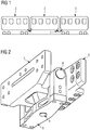
- Fig. 1 shows an example and schematically a train composition with a sedan trolley.
- a train made up of three vehicles is shown, a rail vehicle in sedan-style construction 2 being coupled between two conventional rail vehicles 3.
- a rail vehicle coupling 1 according to the invention is arranged between the rail vehicle in sedan-style construction 2 and the right rail vehicle 1.
- the further coupling of the rail vehicle in sedan design 2 is of a different embodiment, it only has to transmit the weight and operating forces between these vehicles, a ball joint with three degrees of freedom of rotation being able to be used there the rail vehicle coupling 1 at the further end of the vehicle prevents the rail vehicle in sedan-style construction 2 from rolling.
- the rail vehicle in sedan-style construction 2 and the right-hand coupled conventional rail vehicle 3 can therefore only move together about their respective longitudinal axis.
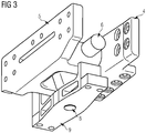
- FIG. 2 shows an example and schematically a rail vehicle coupling.
- a rail vehicle coupling 1 is shown in its installation position, which comprises a joint eye 4 and a joint fork 5.
- These components 4, 5 are each designed for a detachable connection to the car body of a rail vehicle and have holes for screw fastenings as corresponding fastening means. Other fasteners, such as screws, are in Fig. 1 not shown to simplify the illustration.
- the joint eye 4 is fitted with a spherical bearing 7 (in Fig. 1 not visible), through which an axis 6 penetrates, which is connected to the joint fork 5. In this way, there is a connection between the joint fork 5 and the joint eye 6, which blocks all translational degrees of freedom and thus transmits all operating forces in all directions.
- the spherical bearing 7 ensures freedom of all three degrees of freedom of rotation, which is necessary for a movement about the vertical axis and the transverse axis.
- the degree of freedom around the longitudinal axis cannot remain unblocked for driving operation in order to prevent excessive swaying and even tipping of the rail vehicle in sedan-style construction 2.
- the two ends of the axle 6 are designed to be elongated so that they protrude from the joint fork 5 and are each connected to a bracket 9 in a rotatable manner.
- the bracket 9 is essentially U-shaped and has corresponding bores with bearings for receiving the ends of the axle 6.
- the joint eye is equipped with a vertically aligned stub axle 8, the axis of rotation of which is directed through the pivot point of the spherical bearing 7 and which is also rotatably mounted in the bracket 9.
- the bracket 9 locks the rail vehicle coupling 1 by the degree of freedom of the longitudinal axis, so that the two rail vehicles 2, 3 cannot roll to one another.
- the bracket 9 is designed in three parts, as a result of which assembly is significantly simplified.
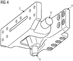
- Fig. 3 shows by way of example and schematically a rail vehicle coupling with a dismantled bracket.
- the rail vehicle coupling 1 is off Fig. 1 shown, wherein the two vertical sections of the U-shaped bracket 9 are removed. In this way, the axis 6, which is extended beyond the joint fork 5, can be clearly seen.
- Fig. 4 shows an example and schematically a rail vehicle coupling without a bracket.
- the rail vehicle coupling 1 is off Fig. 1 shown, the bracket 9 has been completely removed.
- the vertically oriented stub axle 8, which is part of the joint eye, can also be seen in this way.
- Fig. 5 shows an example and schematically a hinge eye of a rail vehicle coupling.
- the articulated eye 4 of a rail vehicle coupling 1 is shown, which comprises a stub axle 8 oriented vertically downwards and in which a spherical bearing 7 is introduced.
- the axis 6 is guided through this spherical bearing 7.
Description
Die Erfindung betrifft eine wanksteife Schienenfahrzeugkupplung für die Kopplung eines Schienenfahrzeugs mit einem Schienenfahrzeug in Sänftenbauweise.The invention relates to a roll-resistant rail vehicle coupling for coupling a rail vehicle to a rail vehicle in sedan-style construction.
Typische Passagierschienenfahrzeuge weisen zwei Fahrwerke auf und können mit weiteren Fahrzeugen gekuppelt werden. Spezielle Zugkonfigurationen erfordern jedoch keine betriebsmäßige Trennbarkeit der Fahrzeugzusammenstellung, sodass andere Fahrzeugkonzepte eingesetzt werden können. Dies betrifft insbesondere U-Bahnen und Straßenbahnen, bei welchen beispielsweise auch sogenannte Sänftenwagen eingesetzt werden, welche kein eigenes Fahrwerk umfassen sondern von den benachbarten Fahrzeugen getragen werden. Solcherart kann eine Einsparung an teuren Fahrwerken realisiert werden, wenn die erlaubte Achslast der Strecke die Erhöhung der Last an den verbleibenden Fahrwerken ermöglicht. Zwischen einem konventionellen und einem Sänftenwagen ist eine spezifische Kupplung vorgesehen, welche die Betriebs- und Gewichtskräfte übermittelt und welche die erforderliche Beweglichkeit für Kurven- Kuppen- und Wannenfahrten sicherstellt. Dafür sind insbesondere Kugelgelenke (Sphärolager) oder Elastomer-Schichtfederlager gut geeignet. Jedoch sind Maßnahmen zu treffen um ein Kippen des Sänftenwagens zu verhindern. Dazu werden die gekuppelten Fahrzeuge mittels eines Lenkers verbunden, wobei der Lenker an jedem Fahrzeug gelenkig angebunden ist und ein Kippen der Fahrzeuge zueinander verhindert, d.h. einen Bewegungsfreiheitsgrad des Kugelgelenks sperrt. Dieser Lenker ist typischerweise im Dachraum der Fahrzeuge angeordnet, wodurch die über den Lenker zu übermittelnden Kräfte aufgrund des Hebelgesetzes im Vergleich zu einer Anordnung im Untergestellbereich reduziert sind. Bei kleinen Fahrzeugen mit untypisch geringem Querschnitt ist eine solche Anordnung jedoch nicht möglich, sodass das Sänftenprinzip gegebenenfalls nicht anwendbar ist. Aus dem Stand der Technik sind Kugelgelenke für die Verbindung von Schienenfahrzeugen bekannt, so offenbart die deutsche Gebrauchsmusterschrift
Der Erfindung liegt daher die Aufgabe zugrunde, eine wanksteife Schienenfahrzeugkupplung für die Kopplung eines Schienenfahrzeugs mit einem Schienenfahrzeug in Sänftenbauweise anzugeben, bei welcher der Rotationsfreiheitsgrad um die Längsachse der Schienenfahrzeugkupplung und damit um die Längsachse der zu koppelnden Schienenfahrzeuge gesperrt ist.The invention is therefore based on the object of specifying a stiff rail vehicle coupling for coupling a rail vehicle to a rail vehicle in sedan-style construction, in which the degree of freedom of rotation around the longitudinal axis of the rail vehicle coupling and thus around the longitudinal axis of the rail vehicles to be coupled is blocked.
Die Aufgabe wird durch eine wanksteife Schienenfahrzeugkupplung mit den Merkmalen des Anspruchs 1 gelöst. Vorteilhafte Ausgestaltungen sind Gegenstand untergeordneter Ansprüche.The object is achieved by a rigid rail vehicle coupling with the features of claim 1 solved. Advantageous configurations are the subject of subordinate claims.
Dem Grundgedanken der Erfindung nach wird eine wanksteife Schienenfahrzeugkupplung für die Verbindung eines Schienenfahrzeugs mit einem Schienenfahrzeug in Sänftenbauweise aufgebaut, welche ein zur lösbaren Verbindung mit einem der beiden Schienenfahrzeuge eingerichtetes Gelenkauge und eine zur lösbaren Verbindung mit dem weiteren der beiden Schienenfahrzeuge eingerichtete Gelenkgabel sowie eine waagrecht ausgerichtete Achse, welche mit der Gelenkgabel verbunden ist und welche ein mit dem Gelenkauge verbundenes Sphärolager durchdringt umfasst, wobei das Gelenkauge einen vertikal orientierten Achsstummel umfasst, dessen Rotationsachse durch den Drehpunkt des Sphärolagers verläuft, wobei dieser Achsstummel drehbeweglich in einen Bügel eingreift, und wobei die Enden der Achse drehbeweglich in dem Bügel gelagert sind.According to the basic idea of the invention, a roll-resistant rail vehicle coupling for the connection of a rail vehicle with a rail vehicle is constructed in sedan-style construction, which has a joint eye set up for detachable connection with one of the two rail vehicles and a joint fork set up for detachable connection with the other of the two rail vehicles as well as a horizontally aligned Axis which is connected to the joint fork and which penetrates a spherical bearing connected to the joint eye, the joint eye including a vertically oriented stub axle whose axis of rotation runs through the pivot point of the spherical bearing, this stub axle engaging rotatably in a bracket, and the ends the axis are rotatably mounted in the bracket.
Dadurch ist der Vorteil erzielbar, eine Wankbewegung der beiden miteinander gekuppelten Schienenfahrzeuge zueinander verhindern zu können, wobei der entsprechende Freiheitsgrad der Kupplung um die Längsachse gesperrt ist. Es ist wesentlich, dass die beiden weiteren Freiheitsgrade um die Hochachse und um die Querachse der Kupplung dabei unbeeinflußt und frei bleiben, sodass die Kupplung bei Kurven- Kuppen- und Wannenfahrten die entsprechenden Verschwenkungen der Fahrzeuge zueinander ermöglicht. Alleine der Freiheitsgrad der Kupplung um die Längsachse, also auch um die Längsachse der gekuppelten Fahrzeuge ist beeinflußt. Somit kann ein wanksteifes Gelenk ohne Lenker im Dachbereich geschaffen werden.This has the advantage of being able to prevent the two rail vehicles coupled to one another from rolling, the corresponding degree of freedom of the coupling about the longitudinal axis being blocked. It is essential that the two other degrees of freedom around the vertical axis and the transverse axis of the coupling remain unaffected and free, so that the coupling enables the corresponding pivoting of the vehicles to one another when driving around bends, crests and tubs. Only the degree of freedom of the coupling around the longitudinal axis, i.e. also around the longitudinal axis of the coupled vehicles, is influenced. In this way, a rigid joint without a handlebar can be created in the roof area.
Erfindungsgemäß ist das Gelenkauge einer Schienenfahrzeugkupplung, welche die zu kuppelnden Schienenfahrzeuge mittels eines Sphärolagers verbindet, mit einem Achsstummel auszustatten. Dabei ist die Drehachse dieses Achsstummels vertikal und so auszurichten, dass sie durch den Drehpunkt des Sphärolagers verläuft. Dieser Achstummel ist in einem Bügel drehbeweglich gelagert. Der Bügel ist so ausgebildet, dass er eine Lagerung für die Achse, welche das Sphärolager durchdringt und somit die Verbindung zwischen den Schienenfahrzeugen herstellt, aufweist. Die Achse ist dazu an ihren Enden verlängert, sodass sie über die Gelenkgabel hinausragt. Diese hinausragenden Enden der Achse sind in einer geeigneten Aufnahme in dem Bügel drehbeweglich zu lagern.According to the invention, the joint eye of a rail vehicle coupling, which connects the rail vehicles to be coupled by means of a spherical bearing, is to be equipped with an axle stub. The axis of rotation of this stub axle is to be aligned vertically so that it runs through the pivot point of the spherical bearing. This stub axle is rotatably mounted in a bracket. The bracket is designed in such a way that it has a bearing for the axle, which penetrates the spherical bearing and thus establishes the connection between the rail vehicles. For this purpose, the axis is lengthened at its ends so that it protrudes beyond the joint fork. These protruding ends of the axle are to be rotatably mounted in a suitable receptacle in the bracket.
Der vertikal orientierte Achsstummel ist vorzugsweise nach unten, d.h. in Richtung des Gleisbetts anzuordnen, da solcherart ungenutzter Bauraum Verwendung findet und mehr Platz oberhalb der Schienenfahrzeugkupplung, insbesondere für den Passagierraum verbleibt.The vertically oriented stub axle should preferably be arranged downwards, i.e. in the direction of the track bed, since unused installation space is used in this way and more space remains above the rail vehicle coupling, especially for the passenger compartment.
Eine bevorzugte Ausführungsform der Erfindung sieht vor, den Bügel mehrteilig, insbesondere dreiteilig auszuführen, da solcherart eine besonders einfache Montage des Bügels erfolgen kann. Dabei kann die wanksteife Schienenfahrzeugkupplung an den zu kuppelnden Fahrzeugen montiert werden und mit der Achse geschlossen werden und der Bügel im Anschluß daran montiert werden. Andernfalls wäre die Achse in einem letzen Arbeitsschritt zu montieren, wobei der Bügel zusätzlich zu der Gelenkgabel und der Gelenkauge exakt zu positionieren wäre und die Einpresskraft der Achse in das Sphärolager geeignet abzustützen wäre. Diese Montagereihenfolge ist wesentlich aufwendiger als einen mehrteiligen Bügel vorzusehen und den Bügel nach dem Montieren der Achse in einzelnen Teilen zu montieren und diese Teile miteinander lösbar zu verbinden.A preferred embodiment of the invention provides for the bracket to be constructed in several parts, in particular in three parts, since in this way a particularly simple assembly of the bracket can take place. The rigid rail vehicle coupling can be mounted on the vehicles to be coupled and closed with the axle and the bracket can then be mounted on it. Otherwise, the axle would have to be assembled in a final work step, the bracket in addition to the joint fork and the joint eye would have to be positioned exactly and the force of the axle pressed into the spherical bearing would be suitably supported. This assembly sequence is much more complex than one to provide multi-part bracket and to assemble the bracket after mounting the axis in individual parts and to releasably connect these parts to one another.
Es zeigen beispielhaft:
- Fig.1
- Zugzusammenstellung mit einem Sänftenwagen.
- Fig.2
- Schienenfahrzeugkupplung.
- Fig.3
- Schienenfahrzeugkupplung, Bügel zerlegt.
- Fig.4
- Schienenfahrzeugkupplung ohne Bügel.
- Fig.5
- Gelenkauge einer Schienenfahrzeugkupplung.
- Fig. 1
- Train composition with a sedan wagon.
- Fig. 2
- Rail vehicle coupling.
- Fig. 3
- Rail vehicle coupling, bracket dismantled.
- Fig. 4
- Rail vehicle coupling without bracket.
- Fig. 5
- Articulated eye of a rail vehicle coupling.
- 1 Schienenfahrzeugkupplung1 rail vehicle coupling
- 2 Schienenfahrzeug in Sänftenbauweise2 rail vehicle in sedan-style construction
- 3 Schienenfahrzeug3 rail vehicle
- 4 Gelenkauge4 joint eyes
- 5 Gelenkgabel5 articulated fork
- 6 Achse6 axis
- 7 Sphärolager7 spherical bearings
- 8 Achsstummel8 stub axles
- 9 Bügel9 bracket
Claims (3)
- Roll-rigid rail vehicle coupling (1) for connecting a rail vehicle (3) to a rail vehicle designed with a suspended central car (2), comprising an articulation head (4) configured for connecting to one of the two rail vehicles (2, 3) in a releasable manner and an articulation body (5) configured for connecting to the other of the two rail vehicles (2, 3) in a releasable manner, as well as a horizontally oriented axle (6) which is connected to the articulation body (5) and which penetrates a spherical bearing (7) connected to the articulation head (4), characterised in that
the articulation head (4) comprises a vertically oriented axle stub (8), the axis of rotation of which runs through the point of rotation of the spherical bearing (7), wherein said axle stub (8) engages into a bracket (9) such that it can move in a rotating manner, and wherein the ends of the axle (6) are mounted in the bracket (9) such that they can move in a rotating manner. - Roll-rigid rail vehicle coupling (1) according to claim 1, characterised in that the axle stub (8) is oriented in the direction of the track bed when the rail vehicle coupling is in the installed position.
- Rail vehicle coupling (1) according to claim 1 or 2, characterised in that the bracket (9) is constructed from a plurality of structural parts that are interconnected in a releasable manner.
Applications Claiming Priority (2)
| Application Number | Priority Date | Filing Date | Title |
|---|---|---|---|
| ATA50828/2017A AT519744B1 (en) | 2017-09-27 | 2017-09-27 | Roll-stiff rail vehicle coupling |
| PCT/EP2018/076060 WO2019063587A1 (en) | 2017-09-27 | 2018-09-26 | Roll-rigid rail vehicle coupling |
Publications (2)
| Publication Number | Publication Date |
|---|---|
| EP3642094A1 EP3642094A1 (en) | 2020-04-29 |
| EP3642094B1 true EP3642094B1 (en) | 2021-06-09 |
Family
ID=63787582
Family Applications (1)
| Application Number | Title | Priority Date | Filing Date |
|---|---|---|---|
| EP18785844.4A Active EP3642094B1 (en) | 2017-09-27 | 2018-09-26 | Roll-rigid rail vehicle coupling |
Country Status (4)
| Country | Link |
|---|---|
| EP (1) | EP3642094B1 (en) |
| CN (1) | CN111108032B (en) |
| AT (1) | AT519744B1 (en) |
| WO (1) | WO2019063587A1 (en) |
Family Cites Families (9)
| Publication number | Priority date | Publication date | Assignee | Title |
|---|---|---|---|---|
| FR1512601A (en) * | 1966-12-30 | 1968-02-09 | Venissieux Atel | Connection device between two parts of a railway vehicle and an intermediate bogie on which they rest |
| FR2695612B1 (en) * | 1992-09-11 | 1994-10-14 | Alsthom Gec | Ball-type attachment device, in particular for railway vehicles. |
| US5520295A (en) * | 1994-07-18 | 1996-05-28 | Hansen Inc. | Articulated rail car connector |
| DE19919536A1 (en) * | 1999-04-29 | 2000-11-02 | Alstom Lhb Gmbh | Articulated coupling for vehicle units of rail vehicles |
| DE10021967A1 (en) * | 2000-05-05 | 2001-11-08 | Scharfenbergkupplung Gmbh & Co | Device for the articulated connection of car bodies of a multi-unit rail vehicle |
| DE502006002843D1 (en) * | 2006-11-22 | 2009-03-26 | Voith Patent Gmbh | Coupling linkage for a car body of a multi-unit vehicle |
| PL3028915T3 (en) * | 2014-12-03 | 2019-08-30 | HÜBNER GmbH & Co. KG | Joint in the roof area between two articulated vehicles |
| CN105460033B (en) * | 2015-11-25 | 2017-08-25 | 长春轨道客车股份有限公司 | It is a kind of to be used to that between the adjacent car body of EMUs the running gear of floor level to be reduced |
| CN206288028U (en) * | 2016-11-15 | 2017-06-30 | 中车长春轨道客车股份有限公司 | Articulator articulated mounting in floor high in rail vehicle |
-
2017
- 2017-09-27 AT ATA50828/2017A patent/AT519744B1/en active
-
2018
- 2018-09-26 CN CN201880063245.5A patent/CN111108032B/en active Active
- 2018-09-26 WO PCT/EP2018/076060 patent/WO2019063587A1/en unknown
- 2018-09-26 EP EP18785844.4A patent/EP3642094B1/en active Active
Also Published As
| Publication number | Publication date |
|---|---|
| CN111108032A (en) | 2020-05-05 |
| AT519744B1 (en) | 2018-10-15 |
| EP3642094A1 (en) | 2020-04-29 |
| AT519744A4 (en) | 2018-10-15 |
| CN111108032B (en) | 2021-09-24 |
| WO2019063587A1 (en) | 2019-04-04 |
Similar Documents
| Publication | Publication Date | Title |
|---|---|---|
| DE4213948A1 (en) | RAIL VEHICLE | |
| EP2084047B1 (en) | Device for mechanically connecting vehicles | |
| DE4404878C1 (en) | Articulated connection for two sub-units of a vehicle | |
| EP2167362B1 (en) | Vehicle with railcar bodies connected in an articulated manner | |
| EP3504096B1 (en) | Articulated vehicle | |
| EP3642094B1 (en) | Roll-rigid rail vehicle coupling | |
| EP0838386B1 (en) | Railway vehicle with at least one running gear and running gear for such a vehicle | |
| EP2061690B1 (en) | Mount for a wheelset link of a rail vehicle | |
| DE490825C (en) | Carriages for railways, trams, rapid transit trains, etc. Like., In particular for articulated car trains | |
| DE102014220775B4 (en) | Rail vehicle in semi-trailer design | |
| AT509524B1 (en) | CHASSIS FRAME SHOOTING | |
| EP3390197B1 (en) | Rail vehicle coupling | |
| DE3924642C2 (en) | ||
| AT518809B1 (en) | Device for blocking the torsional movement between two coupled rail vehicles | |
| DE1963679B2 (en) | Articulated vehicle | |
| DE1077244B (en) | Two-part or multi-part articulated train in which the ends of the wagon are each supported on a single axle and are also guided in the middle of the axle | |
| EP3109121B1 (en) | Bogie for multi-section rail vehicles and multi-section rail vehicle | |
| DE69916710T2 (en) | Rail vehicle with lateral displacement of the bogie pivot | |
| DE102018130813A1 (en) | VEHICLE SEGMENT FOR A MULTIPLE RAIL VEHICLE AND RAIL VEHICLE | |
| DE2523136A1 (en) | Overhead railway gondola suspension mechanism - with additional rotating hinges in suspension carrier and carrier beam | |
| DE1133749B (en) | Articulated connection between the carriages of a carriage unit of an articulated rail train that only consists of two carriages | |
| DE1109203B (en) | Heavy-duty vehicle, in particular rail vehicle for transporting traveling transformers | |
| DE1193981B (en) | Articulated tram cars | |
| DE2548204A1 (en) | COMBINED COUPLING AND BUFFER DEVICE FOR A RAIL VEHICLE | |
| DE10314550A1 (en) | Articulated connection for articulated trains |
Legal Events
| Date | Code | Title | Description |
|---|---|---|---|
| STAA | Information on the status of an ep patent application or granted ep patent |
Free format text: STATUS: UNKNOWN |
|
| STAA | Information on the status of an ep patent application or granted ep patent |
Free format text: STATUS: THE INTERNATIONAL PUBLICATION HAS BEEN MADE |
|
| PUAI | Public reference made under article 153(3) epc to a published international application that has entered the european phase |
Free format text: ORIGINAL CODE: 0009012 |
|
| STAA | Information on the status of an ep patent application or granted ep patent |
Free format text: STATUS: REQUEST FOR EXAMINATION WAS MADE |
|
| 17P | Request for examination filed |
Effective date: 20200122 |
|
| AK | Designated contracting states |
Kind code of ref document: A1 Designated state(s): AL AT BE BG CH CY CZ DE DK EE ES FI FR GB GR HR HU IE IS IT LI LT LU LV MC MK MT NL NO PL PT RO RS SE SI SK SM TR |
|
| AX | Request for extension of the european patent |
Extension state: BA ME |
|
| DAV | Request for validation of the european patent (deleted) | ||
| DAX | Request for extension of the european patent (deleted) | ||
| GRAP | Despatch of communication of intention to grant a patent |
Free format text: ORIGINAL CODE: EPIDOSNIGR1 |
|
| STAA | Information on the status of an ep patent application or granted ep patent |
Free format text: STATUS: GRANT OF PATENT IS INTENDED |
|
| INTG | Intention to grant announced |
Effective date: 20210202 |
|
| GRAS | Grant fee paid |
Free format text: ORIGINAL CODE: EPIDOSNIGR3 |
|
| GRAA | (expected) grant |
Free format text: ORIGINAL CODE: 0009210 |
|
| STAA | Information on the status of an ep patent application or granted ep patent |
Free format text: STATUS: THE PATENT HAS BEEN GRANTED |
|
| AK | Designated contracting states |
Kind code of ref document: B1 Designated state(s): AL AT BE BG CH CY CZ DE DK EE ES FI FR GB GR HR HU IE IS IT LI LT LU LV MC MK MT NL NO PL PT RO RS SE SI SK SM TR |
|
| REG | Reference to a national code |
Ref country code: GB Ref legal event code: FG4D Free format text: NOT ENGLISH |
|
| REG | Reference to a national code |
Ref country code: CH Ref legal event code: EP Ref country code: AT Ref legal event code: REF Ref document number: 1400243 Country of ref document: AT Kind code of ref document: T Effective date: 20210615 |
|
| REG | Reference to a national code |
Ref country code: DE Ref legal event code: R096 Ref document number: 502018005687 Country of ref document: DE |
|
| REG | Reference to a national code |
Ref country code: IE Ref legal event code: FG4D Free format text: LANGUAGE OF EP DOCUMENT: GERMAN |
|
| REG | Reference to a national code |
Ref country code: LT Ref legal event code: MG9D |
|
| PG25 | Lapsed in a contracting state [announced via postgrant information from national office to epo] |
Ref country code: FI Free format text: LAPSE BECAUSE OF FAILURE TO SUBMIT A TRANSLATION OF THE DESCRIPTION OR TO PAY THE FEE WITHIN THE PRESCRIBED TIME-LIMIT Effective date: 20210609 Ref country code: HR Free format text: LAPSE BECAUSE OF FAILURE TO SUBMIT A TRANSLATION OF THE DESCRIPTION OR TO PAY THE FEE WITHIN THE PRESCRIBED TIME-LIMIT Effective date: 20210609 Ref country code: LT Free format text: LAPSE BECAUSE OF FAILURE TO SUBMIT A TRANSLATION OF THE DESCRIPTION OR TO PAY THE FEE WITHIN THE PRESCRIBED TIME-LIMIT Effective date: 20210609 Ref country code: BG Free format text: LAPSE BECAUSE OF FAILURE TO SUBMIT A TRANSLATION OF THE DESCRIPTION OR TO PAY THE FEE WITHIN THE PRESCRIBED TIME-LIMIT Effective date: 20210909 |
|
| REG | Reference to a national code |
Ref country code: NL Ref legal event code: MP Effective date: 20210609 |
|
| PG25 | Lapsed in a contracting state [announced via postgrant information from national office to epo] |
Ref country code: SE Free format text: LAPSE BECAUSE OF FAILURE TO SUBMIT A TRANSLATION OF THE DESCRIPTION OR TO PAY THE FEE WITHIN THE PRESCRIBED TIME-LIMIT Effective date: 20210609 Ref country code: RS Free format text: LAPSE BECAUSE OF FAILURE TO SUBMIT A TRANSLATION OF THE DESCRIPTION OR TO PAY THE FEE WITHIN THE PRESCRIBED TIME-LIMIT Effective date: 20210609 Ref country code: LV Free format text: LAPSE BECAUSE OF FAILURE TO SUBMIT A TRANSLATION OF THE DESCRIPTION OR TO PAY THE FEE WITHIN THE PRESCRIBED TIME-LIMIT Effective date: 20210609 Ref country code: NO Free format text: LAPSE BECAUSE OF FAILURE TO SUBMIT A TRANSLATION OF THE DESCRIPTION OR TO PAY THE FEE WITHIN THE PRESCRIBED TIME-LIMIT Effective date: 20210909 Ref country code: GR Free format text: LAPSE BECAUSE OF FAILURE TO SUBMIT A TRANSLATION OF THE DESCRIPTION OR TO PAY THE FEE WITHIN THE PRESCRIBED TIME-LIMIT Effective date: 20210910 |
|
| PG25 | Lapsed in a contracting state [announced via postgrant information from national office to epo] |
Ref country code: SK Free format text: LAPSE BECAUSE OF FAILURE TO SUBMIT A TRANSLATION OF THE DESCRIPTION OR TO PAY THE FEE WITHIN THE PRESCRIBED TIME-LIMIT Effective date: 20210609 Ref country code: ES Free format text: LAPSE BECAUSE OF FAILURE TO SUBMIT A TRANSLATION OF THE DESCRIPTION OR TO PAY THE FEE WITHIN THE PRESCRIBED TIME-LIMIT Effective date: 20210609 Ref country code: EE Free format text: LAPSE BECAUSE OF FAILURE TO SUBMIT A TRANSLATION OF THE DESCRIPTION OR TO PAY THE FEE WITHIN THE PRESCRIBED TIME-LIMIT Effective date: 20210609 Ref country code: CZ Free format text: LAPSE BECAUSE OF FAILURE TO SUBMIT A TRANSLATION OF THE DESCRIPTION OR TO PAY THE FEE WITHIN THE PRESCRIBED TIME-LIMIT Effective date: 20210609 Ref country code: PT Free format text: LAPSE BECAUSE OF FAILURE TO SUBMIT A TRANSLATION OF THE DESCRIPTION OR TO PAY THE FEE WITHIN THE PRESCRIBED TIME-LIMIT Effective date: 20211011 Ref country code: NL Free format text: LAPSE BECAUSE OF FAILURE TO SUBMIT A TRANSLATION OF THE DESCRIPTION OR TO PAY THE FEE WITHIN THE PRESCRIBED TIME-LIMIT Effective date: 20210609 Ref country code: RO Free format text: LAPSE BECAUSE OF FAILURE TO SUBMIT A TRANSLATION OF THE DESCRIPTION OR TO PAY THE FEE WITHIN THE PRESCRIBED TIME-LIMIT Effective date: 20210609 Ref country code: SM Free format text: LAPSE BECAUSE OF FAILURE TO SUBMIT A TRANSLATION OF THE DESCRIPTION OR TO PAY THE FEE WITHIN THE PRESCRIBED TIME-LIMIT Effective date: 20210609 |
|
| PG25 | Lapsed in a contracting state [announced via postgrant information from national office to epo] |
Ref country code: PL Free format text: LAPSE BECAUSE OF FAILURE TO SUBMIT A TRANSLATION OF THE DESCRIPTION OR TO PAY THE FEE WITHIN THE PRESCRIBED TIME-LIMIT Effective date: 20210609 |
|
| REG | Reference to a national code |
Ref country code: DE Ref legal event code: R097 Ref document number: 502018005687 Country of ref document: DE |
|
| PLBE | No opposition filed within time limit |
Free format text: ORIGINAL CODE: 0009261 |
|
| STAA | Information on the status of an ep patent application or granted ep patent |
Free format text: STATUS: NO OPPOSITION FILED WITHIN TIME LIMIT |
|
| PG25 | Lapsed in a contracting state [announced via postgrant information from national office to epo] |
Ref country code: DK Free format text: LAPSE BECAUSE OF FAILURE TO SUBMIT A TRANSLATION OF THE DESCRIPTION OR TO PAY THE FEE WITHIN THE PRESCRIBED TIME-LIMIT Effective date: 20210609 |
|
| 26N | No opposition filed |
Effective date: 20220310 |
|
| REG | Reference to a national code |
Ref country code: BE Ref legal event code: MM Effective date: 20210930 |
|
| PG25 | Lapsed in a contracting state [announced via postgrant information from national office to epo] |
Ref country code: MC Free format text: LAPSE BECAUSE OF FAILURE TO SUBMIT A TRANSLATION OF THE DESCRIPTION OR TO PAY THE FEE WITHIN THE PRESCRIBED TIME-LIMIT Effective date: 20210609 Ref country code: AL Free format text: LAPSE BECAUSE OF FAILURE TO SUBMIT A TRANSLATION OF THE DESCRIPTION OR TO PAY THE FEE WITHIN THE PRESCRIBED TIME-LIMIT Effective date: 20210609 |
|
| PG25 | Lapsed in a contracting state [announced via postgrant information from national office to epo] |
Ref country code: LU Free format text: LAPSE BECAUSE OF NON-PAYMENT OF DUE FEES Effective date: 20210926 Ref country code: IT Free format text: LAPSE BECAUSE OF FAILURE TO SUBMIT A TRANSLATION OF THE DESCRIPTION OR TO PAY THE FEE WITHIN THE PRESCRIBED TIME-LIMIT Effective date: 20210609 Ref country code: IE Free format text: LAPSE BECAUSE OF NON-PAYMENT OF DUE FEES Effective date: 20210926 Ref country code: BE Free format text: LAPSE BECAUSE OF NON-PAYMENT OF DUE FEES Effective date: 20210930 |
|
| PG25 | Lapsed in a contracting state [announced via postgrant information from national office to epo] |
Ref country code: CY Free format text: LAPSE BECAUSE OF FAILURE TO SUBMIT A TRANSLATION OF THE DESCRIPTION OR TO PAY THE FEE WITHIN THE PRESCRIBED TIME-LIMIT Effective date: 20210609 |
|
| PG25 | Lapsed in a contracting state [announced via postgrant information from national office to epo] |
Ref country code: HU Free format text: LAPSE BECAUSE OF FAILURE TO SUBMIT A TRANSLATION OF THE DESCRIPTION OR TO PAY THE FEE WITHIN THE PRESCRIBED TIME-LIMIT; INVALID AB INITIO Effective date: 20180926 |
|
| PGFP | Annual fee paid to national office [announced via postgrant information from national office to epo] |
Ref country code: AT Payment date: 20230814 Year of fee payment: 6 |
|
| PGFP | Annual fee paid to national office [announced via postgrant information from national office to epo] |
Ref country code: FR Payment date: 20230918 Year of fee payment: 6 |
|
| PGFP | Annual fee paid to national office [announced via postgrant information from national office to epo] |
Ref country code: GB Payment date: 20231009 Year of fee payment: 6 |
|
| PGFP | Annual fee paid to national office [announced via postgrant information from national office to epo] |
Ref country code: DE Payment date: 20231120 Year of fee payment: 6 Ref country code: CH Payment date: 20231205 Year of fee payment: 6 |