EP3641664B1 - Anchor delivery system - Google Patents
Anchor delivery system Download PDFInfo
- Publication number
- EP3641664B1 EP3641664B1 EP18746337.7A EP18746337A EP3641664B1 EP 3641664 B1 EP3641664 B1 EP 3641664B1 EP 18746337 A EP18746337 A EP 18746337A EP 3641664 B1 EP3641664 B1 EP 3641664B1
- Authority
- EP
- European Patent Office
- Prior art keywords
- guide
- drill
- anchor
- shaft
- flexible portion
- Prior art date
- Legal status (The legal status is an assumption and is not a legal conclusion. Google has not performed a legal analysis and makes no representation as to the accuracy of the status listed.)
- Active
Links
Images


Classifications
-
- A—HUMAN NECESSITIES
- A61—MEDICAL OR VETERINARY SCIENCE; HYGIENE
- A61B—DIAGNOSIS; SURGERY; IDENTIFICATION
- A61B17/00—Surgical instruments, devices or methods
- A61B17/04—Surgical instruments, devices or methods for suturing wounds; Holders or packages for needles or suture materials
- A61B17/0482—Needle or suture guides
-
- A—HUMAN NECESSITIES
- A61—MEDICAL OR VETERINARY SCIENCE; HYGIENE
- A61B—DIAGNOSIS; SURGERY; IDENTIFICATION
- A61B17/00—Surgical instruments, devices or methods
- A61B17/04—Surgical instruments, devices or methods for suturing wounds; Holders or packages for needles or suture materials
- A61B17/0469—Suturing instruments for use in minimally invasive surgery, e.g. endoscopic surgery
-
- A—HUMAN NECESSITIES
- A61—MEDICAL OR VETERINARY SCIENCE; HYGIENE
- A61B—DIAGNOSIS; SURGERY; IDENTIFICATION
- A61B17/00—Surgical instruments, devices or methods
- A61B17/16—Instruments for performing osteoclasis; Drills or chisels for bones; Trepans
- A61B17/1613—Component parts
- A61B17/1631—Special drive shafts, e.g. flexible shafts
-
- A—HUMAN NECESSITIES
- A61—MEDICAL OR VETERINARY SCIENCE; HYGIENE
- A61B—DIAGNOSIS; SURGERY; IDENTIFICATION
- A61B17/00—Surgical instruments, devices or methods
- A61B17/16—Instruments for performing osteoclasis; Drills or chisels for bones; Trepans
- A61B17/17—Guides or aligning means for drills, mills, pins or wires
- A61B17/1796—Guides or aligning means for drills, mills, pins or wires for holes for sutures or flexible wires
-
- A—HUMAN NECESSITIES
- A61—MEDICAL OR VETERINARY SCIENCE; HYGIENE
- A61B—DIAGNOSIS; SURGERY; IDENTIFICATION
- A61B17/00—Surgical instruments, devices or methods
- A61B17/04—Surgical instruments, devices or methods for suturing wounds; Holders or packages for needles or suture materials
- A61B17/0401—Suture anchors, buttons or pledgets, i.e. means for attaching sutures to bone, cartilage or soft tissue; Instruments for applying or removing suture anchors
-
- A—HUMAN NECESSITIES
- A61—MEDICAL OR VETERINARY SCIENCE; HYGIENE
- A61B—DIAGNOSIS; SURGERY; IDENTIFICATION
- A61B17/00—Surgical instruments, devices or methods
- A61B17/16—Instruments for performing osteoclasis; Drills or chisels for bones; Trepans
- A61B17/1613—Component parts
- A61B17/1633—Sleeves, i.e. non-rotating parts surrounding the bit shaft, e.g. the sleeve forming a single unit with the bit shaft
-
- A—HUMAN NECESSITIES
- A61—MEDICAL OR VETERINARY SCIENCE; HYGIENE
- A61B—DIAGNOSIS; SURGERY; IDENTIFICATION
- A61B17/00—Surgical instruments, devices or methods
- A61B17/00234—Surgical instruments, devices or methods for minimally invasive surgery
- A61B2017/00292—Surgical instruments, devices or methods for minimally invasive surgery mounted on or guided by flexible, e.g. catheter-like, means
- A61B2017/003—Steerable
- A61B2017/00305—Constructional details of the flexible means
- A61B2017/00309—Cut-outs or slits
-
- A—HUMAN NECESSITIES
- A61—MEDICAL OR VETERINARY SCIENCE; HYGIENE
- A61B—DIAGNOSIS; SURGERY; IDENTIFICATION
- A61B17/00—Surgical instruments, devices or methods
- A61B2017/00831—Material properties
- A61B2017/00862—Material properties elastic or resilient
-
- A—HUMAN NECESSITIES
- A61—MEDICAL OR VETERINARY SCIENCE; HYGIENE
- A61B—DIAGNOSIS; SURGERY; IDENTIFICATION
- A61B17/00—Surgical instruments, devices or methods
- A61B17/04—Surgical instruments, devices or methods for suturing wounds; Holders or packages for needles or suture materials
- A61B17/0401—Suture anchors, buttons or pledgets, i.e. means for attaching sutures to bone, cartilage or soft tissue; Instruments for applying or removing suture anchors
- A61B2017/0409—Instruments for applying suture anchors
-
- A—HUMAN NECESSITIES
- A61—MEDICAL OR VETERINARY SCIENCE; HYGIENE
- A61B—DIAGNOSIS; SURGERY; IDENTIFICATION
- A61B17/00—Surgical instruments, devices or methods
- A61B17/04—Surgical instruments, devices or methods for suturing wounds; Holders or packages for needles or suture materials
- A61B17/0401—Suture anchors, buttons or pledgets, i.e. means for attaching sutures to bone, cartilage or soft tissue; Instruments for applying or removing suture anchors
- A61B2017/0414—Suture anchors, buttons or pledgets, i.e. means for attaching sutures to bone, cartilage or soft tissue; Instruments for applying or removing suture anchors having a suture-receiving opening, e.g. lateral opening
Definitions
- the present disclosure relates to methods and devices for use in surgical procedures and, more specifically, to arthroscopic methods and systems for inserting a suture anchor into bone.
- WO2011009043A1 relates to a system for implanting an anchor into the bone.
- anchor delivery system of this disclosure may include one or more of the following, in any suitable combination.
- Examples of the anchor delivery system of this disclosure include a guide for insertion into a repair site, the guide having a central passage extending therethrough. A distal portion of the guide is curved relative to a longitudinal axis of the guide.
- the system also includes an obturator insertable through the passage of the guide for blocking the passage during insertion of the guide into the repair site.
- the obturator includes a shaft having a flexible portion. A diameter of the flexible portion is selected to allow bending of the obturator so as to pass through the curve of the guide.
- the system further includes a drill insertable through the passage of the guide for forming a hole in a bone at the repair site. The drill including a shank having a flexible portion.
- a diameter of the flexible portion is selected to allow bending of the drill so as to pass through the curve of the guide.
- the system also includes an anchor delivery tool insertable through the passage of the guide for implanting an anchor into the hole.
- the anchor delivery tool includes an elongate member having a flexible portion.
- a surface of the flexible portion includes a plurality of cuts permitting flexing of the anchor delivery tool about the cuts so as to pass through the curve of the guide.
- the elongate member comprises a tapered region between its distal portion and its proximal portion, the distal portion comprising an area of reduced diameter relative to the proximal portion.
- a tip of the guide is configured to stabilize the guide against the bone.
- the distal portion of the guide includes at least one aperture in the surface of the guide in communication with the central passage of the guide. In examples, an angle of the curve is about 15 degrees.
- the diameter of the flexible portion of the shaft of the obturator is selected to be smaller than a diameter of a non-flexible portion of the shaft.
- the obturator includes a conical, atraumatic tip.
- the diameter of the flexible portion of the shank of the drill is selected to be smaller than a diameter of a non-flexible portion of the shank.
- the shank of the drill comprises Nitinol.
- the flexible portion of the shank of the drill includes a series of necked-down regions for increasing flexibility of the flexible portion.
- the flexible portion of the shank of the drill includes a series of lobes for providing a bearing surface and a reduced clearance space between the drill and the guide. The series of lobes are adjacent to a cutting portion formed on or attached to a distal end of the drill.
- a distal end the elongate member of the anchor delivery tool comprises an area of reduced diameter.
- the system further includes an anchor coupled to the anchor delivery tool via a suture routed through a channel of the delivery tool and through a transverse eyelet of the anchor.
- Examples of a method of delivering an anchor to a repair site of this disclosure include passing an obturator through a passage of a guide, the obturator including a shaft having a flexible portion. A diameter of the flexible portion is selected to allow bending of the obturator so as to pass through a curve of the guide.
- the method also includes passing the obturator and the guide over a guide wire implanted in a bone, and placing the tip of the guide against the bone to stabilize the guide.
- the method further includes removing the obturator from the passage of the guide and inserting a drill through the passage of the guide to drill a hole in the bone.
- the drill includes a shank having a flexible portion.
- Examples of an anchor delivery tool of this disclosure include an elongate member having a flexible portion.
- a surface of the flexible portion includes a plurality of cuts permitting flexing of the tool about the cuts so as to pass through a curve of the guide.
- a distal end the elongate member comprises an area of reduced diameter.
- Examples of the anchor delivery tool further include an anchor coupled to the tool via a suture routed through a channel of the tool and through a transverse eyelet of the anchor.
- Examples of a drill apparatus of this disclosure include a drill shaft having a proximal end and distal end.
- the drill apparatus also includes a cutting portion formed on or attached to the distal end of the drill shaft.
- the drill apparatus also includes a plurality of lobes formed on the drill shaft adjacent to the cutting portion. An outer circumferential surface of each lobe has a bearing surface.
- the drill apparatus also includes a plurality of neck segments. Each of the neck segments is located between adjacent instances of the lobes and have a lesser diameter than the plurality of lobes.
- the proximal end of the drill shaft is configured for coupling to a drill.
- the drill shaft is made from nitinol.
- the drill shaft extends through the curved drill guide.
- the curved drill guide includes a handle and a guide shaft coupled to the handle.
- the guide shaft includes a distal portion angled relative to a longitudinal axis of the guide shaft.
- the distal portion includes an end having a serrated edge.
- the drill shaft further includes a counterbore positioned distally to the plurality of lobes.
- the counterbore defines a plurality of cutting elements. In examples, each of the plurality of cutting elements has a cutting angle of between about 90-115°.
- the terms “about” and “substantially” are used represent the inherent degree of uncertainty that may be attributed to any quantitative comparison, value, measurement, or other representation.
- the terms “about” and “substantially” are also used herein to represent the degree by which a quantitative representation may vary from a stated reference without resulting in a change in the basic function of the subject matter at issue.
- “Comprise,” “include,” and/or plural forms of each are open ended and include the listed parts and can include additional parts that are not listed.
- “And/or” is open-ended and includes one or more of the listed parts and combinations of the listed parts.
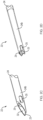
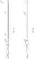
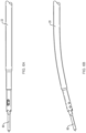
- the anchor delivery system 10 may include a curved guide 20 and a straight guide 22.
- a bend or curve is incorporated into curved guide 20 to direct passing instruments around anatomy during surgery, especially anatomy that prevents a straight trajectory.
- An anchor delivery tool 40 may also be provided which has a flexible shaft portion 42b.
- the anchor delivery tool 40 is capable of delivering an anchor 45, which may be a soft suture anchor, into a bone hole in a repair site of a patient.
- a flexible obturator 60 may also be provided and may be used for insertion through a passage extending through each of the guides 20 and 22.
- a flexible drill 80 may further be provided.
- a cutting portion 88 of the drill 80 may be capable of drilling a hole in bone for insertion of the anchor 45, as further described below.
- the shaft 24 further includes a proximal portion 24a and a distal portion 24b.
- the proximal portion 24a is coupled to the handle 26 and extends distally from the handle 26.
- the handle 26 is slightly tapered toward the shaft 24 and includes ribs 28 along a length of the handle 26 for maintaining a grip on the handle 26 while imparting axial compression and bending into the guides 20, 22 during surgery.
- other means for maintaining a grip known to one of ordinary skill in the art, may be used.
- the distal portion 24b of the shaft 24 includes an area of reduced diameter 30 terminating in a tip 23 configured for stabilizing the guide 20, 22 against bone.
- the distal portion 24b may also include at least one open side window 25.
- the windows 25 may be useful for viewing depth markings on a surface of the passing instruments shown in FIG. 1 .
- the windows 25 are located as distally as possible along the shaft 24, since the space to view them arthroscopically is small in some joints (such as the hip). In other examples, the windows 25 may be located more or less distally along the shaft 24.
- the distal portion 24b of the curved guide 20 is bent or curved relative to the longitudinal axis A of the curved guide 20. In examples, the angle of the bend or curve is about 15°.
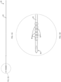
- FIGS. 2C and 2D show examples of the tip 23 of the guide 20, 22 (shown as straight guide 22 for illustrative purposes).
- the distal portion 24b of the guide 20, 22 as shown in FIG. 2C includes a forked tip 23 and an open side window 25 in communication with the central passage 32 of the guide 20, 22.
- the guide 20, 22 as shown in FIG. 2D includes a crown-shaped tip 23 and open side windows 25.
- Other convenient shapes may be used for the tip 23 of the distal portion 24b of the shaft 24, the shape being selected to help stabilize the guide 20, 22 against bone.
- FIG. 3A illustrates examples of the anchor delivery tool 40 and the anchor 45 of the present disclosure.
- the anchor delivery tool 40 includes a shaft 42 and a handle ( FIG. 1 ) coupled to the shaft 42.
- the shaft 42 and the handle may be assembled by heat staking, ultrasonic staking, spin welding, insert molding, or other methods known to one of ordinary skill in the art.
- the shaft 42 comprises stainless steel, but may be made from another biocompatible material known to one of ordinary skill in the art.
- the handle may include suture retaining features for retaining a repair suture 44.
- the shaft 42 includes a proximal portion 42a and a tapered-down distal portion 42b.
- the distal portion 42b comprises an area of reduced diameter 46 which is used for depth stop and relief purposes, as will be further described below.
- a surface of the proximal portion 42a further comprises a laser cut pattern 52 which permits flexing of the proximal portion 42a around the curve of the curved guide 20.
- the anchor 45 is disposed on a proximally-extending boss 54.
- the repair suture 44 extends through a cannulation of the shaft 42 and through opposing slots 48 in the distal portion 42b of the shaft 42.
- the repair suture 44 is also routed through a transverse eyelet 50 of the suture anchor 45.
- the boss 54 is pulled inside the distal portion 42b of the shaft 42 such that the anchor 45 abuts the distal end of the distal portion 42b and is coupled to the delivery tool 40, as shown in FIG. 3B .
- FIG. 4 illustrates an exemplary obturator 60 that allows for easier percutaneous introduction of the guide 20, 22 to a desired site within the body by filling the inner diameter of the central passage 32 of the guide 20, 22 and substantially reducing the possibility of the tip 23 of the guide 20, 22 becoming caught on tissue within the body.
- the obturator 60 includes a shaft 62 coupled to a handle ( FIG. 1 ).
- the shaft 62 and the handle of the obturator 60 are made from stainless steel and plastic, respectively. However, either one could be made from any other biocompatible material known to one of ordinary skill in the art.
- the shaft 62 may be cannulated for passing over a guide wire, as further described below.
- the shaft 62 includes a proximal portion 62a and a tapered-down distal portion 62b.
- a diameter of the distal portion 62b is selected to be smaller than a diameter of the proximal portion 62a to improve flexibility during insertion into the curved guide 20.
- the distal portion 62b allows the shaft 62 to bend along the angled distal portion 24b of the curved guide 20 when the shaft 62 is inserted through the guide 20.
- the distal portion 62b of the obturator 60 may include a conical, atraumatic tip 64 for easier passage of the obturator 60 through the body. In other examples, not shown, the obturator 60 may have a sharp tip 64 allowing for easier and quicker insertion of the guide 20, 22 into the body.
- FIG. 5A shows an exemplary drill 80 for drilling a bone hole in bone.
- a low friction bearing surface may be provided by a shoulder portion 82a of a drill shaft 82.
- the shoulder portion 82a provides reduced clearance between the shaft 82 and the drill guide 20, 22 in which it is installed to maintain centering of the drill shaft 82 with respect to the inside diameter of the drill guide 20, 22.
- a necked down portion 82b of the shaft 82 provides flexibility that allows the shaft 82 to extend through bends in a curved drill guide 20.
- a low friction bearing surface may include one or more sleeve portions 84 that extend around portions of the shaft 82.
- the sleeve portions 84 are operative to further reduce friction between the shaft 82 and the drill guide 20, 22 and to center the drill shaft 82 relative to the drill guide 20, 22.
- the drill shaft 82 may be made of steel, nitinol or other metals.
- the sleeve portions 84 may be made of a plastic heat shrink material such as PEEK or PTFE, for example.
- the sleeve portions 84 may comprise plastic members that are press-fit or over-molded over the drill shaft 82.
- the bearing material can be fiber reinforced to provide extra rigidity, for example.
- the coefficient of friction between the plastic sleeve portions 84 and an inner surface of the metal drill guide 20, 22 is lower than between a metal surface of the drill shaft 82 and a metal inner surface of the drill guide 20, 22.
- the low friction bearing surface and/or the drill guide 20, 22 may be made from materials such as dissimilar metals with improved frictional properties to reduce particulate generation.
- the low friction bearing surface may include one or more separately created bearings that are later assembled onto the drill shaft 82.
- the low friction bearing surface takes up clearance space between the drill 80 and the drill guide 20, 22 to center the drill shaft 82 within the guide 20, 22, which improves alignment between the drill trajectory and the guide 20, 22.
- the reduced friction provided between the drill shaft 82 and the drill guide 20, 22 also allows a smoother motion of the drill shaft 82 within the drill guide 20, 22, which improves controllability of the drill 80.
- the reduced friction also reduces particulate generation, which can be harmful in a surgical environment.
- a drill shaft 82 includes a series of lobes 86 and necked down regions 88.
- the necked down regions 88 increase flexibility of the drill shaft 82.
- the series of lobes 86 are located along the drill shaft 82 to provide a bearing surface between the drill shaft 82 and the drill guide 20, 22.
- the lobes 86 are adjacent a cutting portion 89 that is formed on or attached to the distal end of the drill shaft 82.
- the lobes 86 can vary in number, size shape and spacing.
- the lobes 86 also provide reduced clearance space between the drill shaft 82 and the drill guide 20, 22.
- the reduced clearance increases alignment of the trajectory of the drill shaft 82 within the drill guide 20, 22.
- spacing between the lobes 86 and the inner surface of the drill guide 20, 22 reduces cocking of the drill 80 as it exits the guide 20, 22.
- the necked down regions 88 between the lobes 86 have reduced cross sectional area and thus lower the area moment of inertia of the drill shaft 82. Deflection required for the drill shaft 82 to pass through a curved drill guide 20 is provided by the reduced area moment of inertia in the necked down region 88. This allows the drill shaft 82 to bend with less force than a conventional drill shaft.
- FIGS. 5D and 5E illustrate an example of a counterbore 92 of the drill shaft 82 located distally to the series of lobes 86.
- the counterbore 92 can be used to undercut the cutting portion 89 for reduction of the drilling force needed to move the drill 80 in hard bone media.
- each of a plurality of cutting elements 94 defined by the counterbore 92 have a cutting angle A of between about 90-115° to allow for bone chip removal.
- aspects of the present disclosure describe a drill shaft 82 having a series of lobes 86 and necked down regions 88 to reduce the area moment of inertia of the shaft 82 to increase flexibility of the drill 80
- the disclosed drill 80 may include other geometries that change the area moment of inertia of the shaft 82 to increase flexibility of the drill shaft 82.
- flexibility of the drill 80 may be achieved via collapsible geometries that permit deflection or portions of the drill shaft 82. As shown in FIGS. 6A and 6B , whether the drill 80 exits the straight guide 22 ( FIG. 6A ) or the curved guide 20 ( FIG. 6B ), the drill 80 is aligned with the trajectory of the guide 20, 22.
- the obturator 60 is inserted through the central passage 32 of the guide 20, 22 (shown for exemplary purposes as straight guide 22) and the combination is then passed over a guide wire 90 previously implanted in bone 200 at the desired site for tissue repair.
- the tip 23 of the guide 20, 22 is placed against the bone 200 to stabilize the guide 20, 22 for subsequent drilling and delivery of the suture anchor 45.
- the guide wire 90 is then removed from the bone 200 and the obturator 60 is removed from the central passage 32 of the guide 20, 22.
- the drill 80 is inserted into the central passage 32 of the guide 20, 22 and a drive unit (not shown) is coupled to the drill 80.
- the drive unit is operated to rotate the drill 80 to drill a hole 100 in the bone 200.
- the drill 80 is then removed from the central passage 32 of the guide 20, 22.
- the anchor delivery tool 40 is disposed within the central passage 32 of the guide 20, 22 for delivery of the anchor 45 into the previously-drilled hole 100.
- the anchor 45 is advanced into the hole 100 in an axially-oriented manner by tapping on a proximal portion of the handle (not shown) of the anchor delivery tool 40.
- the proximal portion of the anchor 45 is positioned below a surface 201 of the bone 200.
- the area of reduced diameter 46 included on the distal portion 42b of the anchor delivery tool 40 substantially reduces the possibility of the distal portion 42b getting stuck in the hole 100 of the bone 200 during delivery of the anchor 45.
- the area of reduced diameter 46 can also serve as a depth stop to ensure that the proximal portion of the anchor 45 is positioned a correct distance below a surface 201 of the bone 200.
Landscapes
- Health & Medical Sciences (AREA)
- Surgery (AREA)
- Life Sciences & Earth Sciences (AREA)
- Biomedical Technology (AREA)
- Medical Informatics (AREA)
- Veterinary Medicine (AREA)
- Public Health (AREA)
- Engineering & Computer Science (AREA)
- General Health & Medical Sciences (AREA)
- Heart & Thoracic Surgery (AREA)
- Nuclear Medicine, Radiotherapy & Molecular Imaging (AREA)
- Molecular Biology (AREA)
- Animal Behavior & Ethology (AREA)
- Dentistry (AREA)
- Oral & Maxillofacial Surgery (AREA)
- Orthopedic Medicine & Surgery (AREA)
- Rheumatology (AREA)
- Surgical Instruments (AREA)
Applications Claiming Priority (3)
| Application Number | Priority Date | Filing Date | Title |
|---|---|---|---|
| US201762523442P | 2017-06-22 | 2017-06-22 | |
| US201762523447P | 2017-06-22 | 2017-06-22 | |
| PCT/US2018/039024 WO2018237280A1 (en) | 2017-06-22 | 2018-06-22 | Anchor delivery system |
Publications (2)
| Publication Number | Publication Date |
|---|---|
| EP3641664A1 EP3641664A1 (en) | 2020-04-29 |
| EP3641664B1 true EP3641664B1 (en) | 2025-04-09 |
Family
ID=63036313
Family Applications (1)
| Application Number | Title | Priority Date | Filing Date |
|---|---|---|---|
| EP18746337.7A Active EP3641664B1 (en) | 2017-06-22 | 2018-06-22 | Anchor delivery system |
Country Status (6)
| Country | Link |
|---|---|
| US (2) | US11202643B2 (OSRAM) |
| EP (1) | EP3641664B1 (OSRAM) |
| JP (1) | JP7267938B2 (OSRAM) |
| CN (1) | CN110662493B (OSRAM) |
| AU (1) | AU2018290346B2 (OSRAM) |
| WO (1) | WO2018237280A1 (OSRAM) |
Families Citing this family (13)
| Publication number | Priority date | Publication date | Assignee | Title |
|---|---|---|---|---|
| US9427330B2 (en) * | 2011-09-06 | 2016-08-30 | Globus Medical, Inc. | Spinal plate |
| US11833034B2 (en) | 2016-01-13 | 2023-12-05 | Shifamed Holdings, Llc | Prosthetic cardiac valve devices, systems, and methods |
| CN119564382A (zh) | 2018-08-21 | 2025-03-07 | 施菲姆德控股有限责任公司 | 人工心脏瓣膜装置、系统和方法 |
| EP3860519A4 (en) | 2018-10-05 | 2022-07-06 | Shifamed Holdings, LLC | HEART VALVE PROSTHESIS, SYSTEMS AND PROCEDURES |
| AU2019362078B2 (en) | 2018-10-19 | 2025-08-07 | Shifamed Holdings, Llc | Adjustable medical device |
| US11471282B2 (en) | 2019-03-19 | 2022-10-18 | Shifamed Holdings, Llc | Prosthetic cardiac valve devices, systems, and methods |
| EP4110207A1 (en) * | 2020-02-28 | 2023-01-04 | Bard Access Systems, Inc. | Flexible intraosseous obturator |
| CN116456937A (zh) | 2020-08-31 | 2023-07-18 | 施菲姆德控股有限责任公司 | 假体瓣膜递送系统 |
| CN111904501A (zh) * | 2020-09-04 | 2020-11-10 | 北京市春立正达医疗器械股份有限公司 | 一种锚钉植入器 |
| CN112353442B (zh) * | 2020-11-11 | 2022-06-10 | 贺业腾 | 一种肩袖损伤修复用锚钉系统 |
| US12329635B2 (en) | 2020-12-04 | 2025-06-17 | Shifamed Holdings, Llc | Flared prosthetic cardiac valve delivery devices and systems |
| US12201521B2 (en) | 2021-03-22 | 2025-01-21 | Shifamed Holdings, Llc | Anchor position verification for prosthetic cardiac valve devices |
| CN119791913A (zh) * | 2025-03-17 | 2025-04-11 | 苏州星悦智慧医疗科技有限公司 | 骨髓刺激锥系统 |
Family Cites Families (21)
| Publication number | Priority date | Publication date | Assignee | Title |
|---|---|---|---|---|
| US4265231A (en) * | 1979-04-30 | 1981-05-05 | Scheller Jr Arnold D | Curved drill attachment for bone drilling uses |
| US4541423A (en) * | 1983-01-17 | 1985-09-17 | Barber Forest C | Drilling a curved hole |
| CA2124996C (en) * | 1993-06-21 | 2006-01-31 | Thomas W. Sander | Orthopedic fastener applicator |
| EP2399531B1 (en) * | 2002-08-08 | 2016-01-27 | Surgibit Ip Holdings Pty Limited | Drill bit |
| US7131974B2 (en) * | 2003-10-14 | 2006-11-07 | Keyer Thomas R | Surgical drill guide |
| ES2431120T3 (es) * | 2005-01-05 | 2013-11-25 | Nlt Spine Ltd. | Dispositivo de introducción recta que adopta una configuración curvada |
| JP2009528910A (ja) * | 2006-03-06 | 2009-08-13 | イマコー・エルエルシー | 調整可能な曲げセクションを有する経食道超音波プローブ |
| US20080188854A1 (en) * | 2007-01-05 | 2008-08-07 | University Of Florida Research Foundation, Inc. | Surgical Anchor Delivery System |
| US8808338B2 (en) * | 2007-12-05 | 2014-08-19 | Syntorr, Inc. | Flexible bone screw |
| CN201371265Y (zh) * | 2009-02-13 | 2009-12-30 | 赵顺权 | 定心沉孔钻头 |
| US8911474B2 (en) * | 2009-07-16 | 2014-12-16 | Howmedica Osteonics Corp. | Suture anchor implantation instrumentation system |
| US9179905B2 (en) * | 2009-07-17 | 2015-11-10 | Pivot Medical, Inc. | Method and apparatus for re-attaching the labrum to the acetabulum, including the provision and use of a novel suture anchor system |
| FR2960764B1 (fr) * | 2010-06-04 | 2012-06-08 | Spineart Sa | Instruments pour la chirurgie rachidienne mini-invasive et leurs applications |
| JP2013542776A (ja) * | 2010-10-06 | 2013-11-28 | スミス アンド ネフュー インコーポレーテッド | 組織修復において使用するためのシステム |
| US20130012951A1 (en) * | 2011-07-08 | 2013-01-10 | Carefusion 207, Inc. | Systems and methods for treating a spine through a single vertebral body insertion point |
| US9788844B2 (en) * | 2011-12-16 | 2017-10-17 | Medos International Sarl | Methods and systems for attaching tissue to bone |
| US8821494B2 (en) * | 2012-08-03 | 2014-09-02 | Howmedica Osteonics Corp. | Surgical instruments and methods of use |
| US9198651B2 (en) * | 2012-09-26 | 2015-12-01 | Medos International Sarl | Anchor inserter |
| US9101373B2 (en) * | 2012-10-15 | 2015-08-11 | Biomet Sports Medicine, Llc | Self-centering drill guide |
| CA2895842A1 (en) * | 2013-01-07 | 2014-07-10 | Pivot Medical, Inc. | Flexible drill bit and angled drill guide for use with the same |
| US20160143651A1 (en) * | 2014-11-19 | 2016-05-26 | Smith & Nephew, Inc. | Windowed instrument drill guide and corresponding friction reducing instrument |
-
2018
- 2018-06-22 EP EP18746337.7A patent/EP3641664B1/en active Active
- 2018-06-22 JP JP2019566697A patent/JP7267938B2/ja active Active
- 2018-06-22 WO PCT/US2018/039024 patent/WO2018237280A1/en not_active Ceased
- 2018-06-22 AU AU2018290346A patent/AU2018290346B2/en active Active
- 2018-06-22 US US16/623,474 patent/US11202643B2/en active Active
- 2018-06-22 CN CN201880034368.6A patent/CN110662493B/zh active Active
-
2021
- 2021-11-15 US US17/526,044 patent/US11903593B2/en active Active
Also Published As
| Publication number | Publication date |
|---|---|
| WO2018237280A1 (en) | 2018-12-27 |
| US11202643B2 (en) | 2021-12-21 |
| US20220071640A1 (en) | 2022-03-10 |
| AU2018290346B2 (en) | 2024-02-29 |
| US11903593B2 (en) | 2024-02-20 |
| CN110662493A (zh) | 2020-01-07 |
| CN110662493B (zh) | 2023-05-09 |
| JP2020525069A (ja) | 2020-08-27 |
| EP3641664A1 (en) | 2020-04-29 |
| US20200113586A1 (en) | 2020-04-16 |
| AU2018290346A1 (en) | 2019-12-19 |
| JP7267938B2 (ja) | 2023-05-02 |
Similar Documents
| Publication | Publication Date | Title |
|---|---|---|
| US11903593B2 (en) | Anchor delivery system | |
| US9931150B2 (en) | Anchor delivery system | |
| AU2011312049B2 (en) | A system for use in tissue repair | |
| KR101926339B1 (ko) | 수술용 네일 | |
| US10159478B2 (en) | Suture anchor implantation instrumentation system | |
| US11045210B2 (en) | Flexible spinal driver or drill with a malleable core, and/or fixed core radius | |
| US10517613B2 (en) | Systems, devices, and methods for guiding surgical devices into bone | |
| JP7209642B2 (ja) | 外科手術ドリルガイドおよびシステム | |
| US20150088197A1 (en) | Bone Anchor Inserter | |
| WO2018183837A1 (en) | Fixation device and method of using the same |
Legal Events
| Date | Code | Title | Description |
|---|---|---|---|
| STAA | Information on the status of an ep patent application or granted ep patent |
Free format text: STATUS: UNKNOWN |
|
| STAA | Information on the status of an ep patent application or granted ep patent |
Free format text: STATUS: THE INTERNATIONAL PUBLICATION HAS BEEN MADE |
|
| PUAI | Public reference made under article 153(3) epc to a published international application that has entered the european phase |
Free format text: ORIGINAL CODE: 0009012 |
|
| STAA | Information on the status of an ep patent application or granted ep patent |
Free format text: STATUS: REQUEST FOR EXAMINATION WAS MADE |
|
| 17P | Request for examination filed |
Effective date: 20200122 |
|
| AK | Designated contracting states |
Kind code of ref document: A1 Designated state(s): AL AT BE BG CH CY CZ DE DK EE ES FI FR GB GR HR HU IE IS IT LI LT LU LV MC MK MT NL NO PL PT RO RS SE SI SK SM TR |
|
| AX | Request for extension of the european patent |
Extension state: BA ME |
|
| DAV | Request for validation of the european patent (deleted) | ||
| DAX | Request for extension of the european patent (deleted) | ||
| STAA | Information on the status of an ep patent application or granted ep patent |
Free format text: STATUS: EXAMINATION IS IN PROGRESS |
|
| 17Q | First examination report despatched |
Effective date: 20230123 |
|
| GRAP | Despatch of communication of intention to grant a patent |
Free format text: ORIGINAL CODE: EPIDOSNIGR1 |
|
| STAA | Information on the status of an ep patent application or granted ep patent |
Free format text: STATUS: GRANT OF PATENT IS INTENDED |
|
| INTG | Intention to grant announced |
Effective date: 20241126 |
|
| RIC1 | Information provided on ipc code assigned before grant |
Ipc: A61B 17/04 20060101AFI20241118BHEP |
|
| P01 | Opt-out of the competence of the unified patent court (upc) registered |
Free format text: CASE NUMBER: APP_63331/2024 Effective date: 20241203 |
|
| GRAS | Grant fee paid |
Free format text: ORIGINAL CODE: EPIDOSNIGR3 |
|
| GRAA | (expected) grant |
Free format text: ORIGINAL CODE: 0009210 |
|
| STAA | Information on the status of an ep patent application or granted ep patent |
Free format text: STATUS: THE PATENT HAS BEEN GRANTED |
|
| AK | Designated contracting states |
Kind code of ref document: B1 Designated state(s): AL AT BE BG CH CY CZ DE DK EE ES FI FR GB GR HR HU IE IS IT LI LT LU LV MC MK MT NL NO PL PT RO RS SE SI SK SM TR |
|
| REG | Reference to a national code |
Ref country code: GB Ref legal event code: FG4D |
|
| REG | Reference to a national code |
Ref country code: CH Ref legal event code: EP |
|
| REG | Reference to a national code |
Ref country code: DE Ref legal event code: R096 Ref document number: 602018080951 Country of ref document: DE |
|
| REG | Reference to a national code |
Ref country code: IE Ref legal event code: FG4D |
|
| PGFP | Annual fee paid to national office [announced via postgrant information from national office to epo] |
Ref country code: DE Payment date: 20250402 Year of fee payment: 8 |
|
| PGFP | Annual fee paid to national office [announced via postgrant information from national office to epo] |
Ref country code: GB Payment date: 20250519 Year of fee payment: 8 |
|
| PGFP | Annual fee paid to national office [announced via postgrant information from national office to epo] |
Ref country code: FR Payment date: 20250508 Year of fee payment: 8 |
|
| REG | Reference to a national code |
Ref country code: NL Ref legal event code: MP Effective date: 20250409 |
|
| PG25 | Lapsed in a contracting state [announced via postgrant information from national office to epo] |
Ref country code: NL Free format text: LAPSE BECAUSE OF FAILURE TO SUBMIT A TRANSLATION OF THE DESCRIPTION OR TO PAY THE FEE WITHIN THE PRESCRIBED TIME-LIMIT Effective date: 20250409 |
|
| REG | Reference to a national code |
Ref country code: AT Ref legal event code: MK05 Ref document number: 1782798 Country of ref document: AT Kind code of ref document: T Effective date: 20250409 |
|
| PG25 | Lapsed in a contracting state [announced via postgrant information from national office to epo] |
Ref country code: PT Free format text: LAPSE BECAUSE OF FAILURE TO SUBMIT A TRANSLATION OF THE DESCRIPTION OR TO PAY THE FEE WITHIN THE PRESCRIBED TIME-LIMIT Effective date: 20250811 Ref country code: ES Free format text: LAPSE BECAUSE OF FAILURE TO SUBMIT A TRANSLATION OF THE DESCRIPTION OR TO PAY THE FEE WITHIN THE PRESCRIBED TIME-LIMIT Effective date: 20250409 Ref country code: FI Free format text: LAPSE BECAUSE OF FAILURE TO SUBMIT A TRANSLATION OF THE DESCRIPTION OR TO PAY THE FEE WITHIN THE PRESCRIBED TIME-LIMIT Effective date: 20250409 |
|
| REG | Reference to a national code |
Ref country code: LT Ref legal event code: MG9D |
|
| PG25 | Lapsed in a contracting state [announced via postgrant information from national office to epo] |
Ref country code: GR Free format text: LAPSE BECAUSE OF FAILURE TO SUBMIT A TRANSLATION OF THE DESCRIPTION OR TO PAY THE FEE WITHIN THE PRESCRIBED TIME-LIMIT Effective date: 20250710 Ref country code: NO Free format text: LAPSE BECAUSE OF FAILURE TO SUBMIT A TRANSLATION OF THE DESCRIPTION OR TO PAY THE FEE WITHIN THE PRESCRIBED TIME-LIMIT Effective date: 20250709 |
|
| PG25 | Lapsed in a contracting state [announced via postgrant information from national office to epo] |
Ref country code: PL Free format text: LAPSE BECAUSE OF FAILURE TO SUBMIT A TRANSLATION OF THE DESCRIPTION OR TO PAY THE FEE WITHIN THE PRESCRIBED TIME-LIMIT Effective date: 20250409 |
|
| PG25 | Lapsed in a contracting state [announced via postgrant information from national office to epo] |
Ref country code: BG Free format text: LAPSE BECAUSE OF FAILURE TO SUBMIT A TRANSLATION OF THE DESCRIPTION OR TO PAY THE FEE WITHIN THE PRESCRIBED TIME-LIMIT Effective date: 20250409 |
|
| PG25 | Lapsed in a contracting state [announced via postgrant information from national office to epo] |
Ref country code: HR Free format text: LAPSE BECAUSE OF FAILURE TO SUBMIT A TRANSLATION OF THE DESCRIPTION OR TO PAY THE FEE WITHIN THE PRESCRIBED TIME-LIMIT Effective date: 20250409 |
|
| PG25 | Lapsed in a contracting state [announced via postgrant information from national office to epo] |
Ref country code: AT Free format text: LAPSE BECAUSE OF FAILURE TO SUBMIT A TRANSLATION OF THE DESCRIPTION OR TO PAY THE FEE WITHIN THE PRESCRIBED TIME-LIMIT Effective date: 20250409 |
|
| PG25 | Lapsed in a contracting state [announced via postgrant information from national office to epo] |
Ref country code: RS Free format text: LAPSE BECAUSE OF FAILURE TO SUBMIT A TRANSLATION OF THE DESCRIPTION OR TO PAY THE FEE WITHIN THE PRESCRIBED TIME-LIMIT Effective date: 20250709 |
|
| PG25 | Lapsed in a contracting state [announced via postgrant information from national office to epo] |
Ref country code: IS Free format text: LAPSE BECAUSE OF FAILURE TO SUBMIT A TRANSLATION OF THE DESCRIPTION OR TO PAY THE FEE WITHIN THE PRESCRIBED TIME-LIMIT Effective date: 20250809 |
|
| PG25 | Lapsed in a contracting state [announced via postgrant information from national office to epo] |
Ref country code: LV Free format text: LAPSE BECAUSE OF FAILURE TO SUBMIT A TRANSLATION OF THE DESCRIPTION OR TO PAY THE FEE WITHIN THE PRESCRIBED TIME-LIMIT Effective date: 20250409 |