EP3640970B1 - Ionenführungsvorrichtung - Google Patents
Ionenführungsvorrichtung Download PDFInfo
- Publication number
- EP3640970B1 EP3640970B1 EP19209836.6A EP19209836A EP3640970B1 EP 3640970 B1 EP3640970 B1 EP 3640970B1 EP 19209836 A EP19209836 A EP 19209836A EP 3640970 B1 EP3640970 B1 EP 3640970B1
- Authority
- EP
- European Patent Office
- Prior art keywords
- ion
- ion guide
- peak
- guide
- ions
- Prior art date
- Legal status (The legal status is an assumption and is not a legal conclusion. Google has not performed a legal analysis and makes no representation as to the accuracy of the status listed.)
- Active
Links
Images


Classifications
-
- H—ELECTRICITY
- H01—ELECTRIC ELEMENTS
- H01J—ELECTRIC DISCHARGE TUBES OR DISCHARGE LAMPS
- H01J49/00—Particle spectrometers or separator tubes
- H01J49/02—Details
-
- H—ELECTRICITY
- H01—ELECTRIC ELEMENTS
- H01J—ELECTRIC DISCHARGE TUBES OR DISCHARGE LAMPS
- H01J49/00—Particle spectrometers or separator tubes
- H01J49/02—Details
- H01J49/06—Electron- or ion-optical arrangements
- H01J49/062—Ion guides
-
- H—ELECTRICITY
- H01—ELECTRIC ELEMENTS
- H01J—ELECTRIC DISCHARGE TUBES OR DISCHARGE LAMPS
- H01J49/00—Particle spectrometers or separator tubes
- H01J49/02—Details
- H01J49/06—Electron- or ion-optical arrangements
- H01J49/062—Ion guides
- H01J49/065—Ion guides having stacked electrodes, e.g. ring stack, plate stack
-
- H—ELECTRICITY
- H01—ELECTRIC ELEMENTS
- H01J—ELECTRIC DISCHARGE TUBES OR DISCHARGE LAMPS
- H01J49/00—Particle spectrometers or separator tubes
- H01J49/26—Mass spectrometers or separator tubes
Definitions
- the present invention relates to an ion guiding device.
- the preferred embodiment relates to a mass spectrometer, a device for guiding ions, a method of mass spectrometry and a method of guiding ions.
- Ion guides are known wherein ions are confined or constrained to flow along the central longitudinal axis of a linear ion guide.
- the central axis of the ion guide is coincident with the centre of a radially symmetric pseudo-potential valley.
- the pseudo-potential valley is formed within the ion guide as a result of applying RF voltages to the electrodes comprising the ion guide. Ions enter and exit the ion guide along the central longitudinal axis of the ion guide.
- US 6,753,523 discloses a mass spectrometer with a multipole ion guide.
- US 2005/285029 discloses a storage device for a molecular detector.
- an ion guiding device as claimed in claim 1.
- Ions are preferably transferred radially or with a non-zero radial component of velocity across one or more radial or longitudinal pseudo-potential barriers disposed between the first ion guide and the second ion guide which are substantially parallel to one another.
- Embodiments of the present invention are contemplated wherein ions are transferred from the first ion guide to the second ion guide and/or from the second ion guide to the first ion guide multiple times or at least 2, 3, 4, 5, 6, 7, 8, 9 or 10 times. Ions may, for example, be repeatedly switched back and forth between the two or more ion guides.
- Adjacent or neighbouring rod electrodes are preferably maintained at opposite phase of an AC or RF voltage.
- the first ion guide and/or the second ion guide are axially segmented so as to comprise at least 2, 3, 4, 5, 6, 7, 8, 9, 10, 11, 12, 13, 14, 15, 16, 17, 18, 19 or 20 axial segments, wherein at least 1%, 5%, 10%, 20%, 30%, 40%, 50%, 60%, 70%, 80%, 90%, 95% or 100% of the first plurality of electrodes in an axial segment and/or at least 1%, 5%, 10%, 20%, 30%, 40%, 50%, 60%, 70%, 80%, 90%, 95% or 100% of the second plurality of electrodes in an axial segment are maintained in use at the same DC voltage.
- the first device is preferably arranged and adapted to create:
- the second device is preferably arranged and adapted:
- one or more crossover regions, sections or junctions are arranged between the first ion guide and the second ion guide wherein at least some ions may be transferred or are caused to be transferred from the first ion guide into the second ion guide and/or wherein at least some ions may be transferred from the second ion guide into the first ion guide.
- a first pseudo-potential valley is preferably formed within the first ion guide such that the first pseudo-potential valley has a first longitudinal axis and likewise in use a second pseudo-potential valley is preferably formed within the second ion guide such that the second pseudo-potential valley has a second longitudinal axis, wherein:
- the first ion guide and/or the second ion guide preferably comprise:
- the ion guiding device may be arranged and adapted so as to form:
- the first ion guide and/or the second ion guide may comprise n axial segments or may be segmented into n separate axial segments, wherein n is selected from the group consisting of: (i) 1-10; (ii) 11-20; (iii) 21-30; (iv) 31-40; (v) 41-50; (vi) 51-60; (vii) 61-70; (viii) 71-80; (ix) 81-90; (x) 91-100; and (xi) > 100; and wherein:
- the first ion guide and/or the second ion guide preferably:
- the ion guiding device preferably further comprises a first AC or RF voltage supply for applying a first AC or RF voltage to at least some of the plurality of rod electrodes of the first ion guide and/or the plurality of rod electrodes of the second ion guide, wherein either:
- the ion guiding device further comprises a third device arranged and adapted to progressively increase, progressively decrease, progressively vary, scan, linearly increase, linearly decrease, increase in a stepped, progressive or other manner or decrease in a stepped, progressive or other manner the amplitude of the first AC or RF voltage by x 1 Volts over a time period t 1 , wherein:
- one or more first axial time averaged or pseudo-potential barriers, corrugations or wells are created, in use, along at least 1%, 5%, 10%, 20%, 30%, 40%, 50%, 60%, 70%, 80%, 90% or 95% of the axial length of the first ion guide.
- the ion guiding device preferably further comprises a second AC or RF voltage supply for applying a second AC or RF voltage to at least some of the plurality of rod electrodes of the first and/or second ion guide, wherein either:
- the ion guiding device preferably further comprises a fourth device arranged and adapted to progressively increase, progressively decrease, progressively vary, scan, linearly increase, linearly decrease, increase in a stepped, progressive or other manner or decrease in a stepped, progressive or other manner the amplitude of the second AC or RF voltage by x 2 Volts over a time period t 2 , wherein:
- one or more second axial time averaged or pseudo-potential barriers, corrugations or wells are preferably created, in use, along at least 1%, 5%, 10%, 20%, 30%, 40%, 50%, 60%, 70%, 80%, 90% or 95% of the axial length of the second ion guide.
- a non-zero axial and/or radial DC voltage gradient is preferably maintained in use across or along one or more sections or portions of the first ion guide and/or the second ion guide.
- the ion guiding device further comprises a device for driving or urging ions upstream and/or downstream along or around at least 1%, 5%, 10%, 20%, 30%, 40%, 50%, 60%, 70%, 80%, 90%, 95% or 100% of the length or ion guiding path of the first ion guide and/or the second ion guide, wherein the device comprises:
- the ion guiding device preferably further comprises fifth device arranged and adapted to progressively increase, progressively decrease, progressively vary, scan, linearly increase, linearly decrease, increase in a stepped, progressive or other manner or decrease in a stepped, progressive or other manner the amplitude, height or depth of the one or more transient DC voltages or potentials or DC voltage or potential waveforms by x 3 Volts over a time period t 3 ; wherein x 3 is selected from the group consisting of: (i) ⁇ 0.1 V; (ii) 0.1-0.2 V; (iii) 0.2-0.3 V; (iv) 0.3-0.4 V; (v) 0.4-0.5 V; (vi) 0.5-0.6 V; (vii) 0.6-0.7 V; (viii) 0.7-0.8 V; (ix) 0.8-0.9 V; (x) 0.9-1.0 V; (xi) 1.0-1.5 V; (xii) 1.5-2.0 V; (xiii) 2.0-2.5 V; (xiv
- the ion guiding device preferably further comprises sixth device arranged and adapted to progressively increase, progressively decrease, progressively vary, scan, linearly increase, linearly decrease, increase in a stepped, progressive or other manner or decrease in a stepped, progressive or other manner the velocity or rate at which the one or more transient DC voltages or potentials or DC voltage or potential waveforms are applied to the electrodes by x 4 m/s over a time period t 4 ; wherein x 4 is selected from the group consisting of: (i) ⁇ 1; (ii) 1-2; (iii) 2-3; (iv) 3-4; (v) 4-5; (vi) 5-6; (vii) 6-7; (viii) 7-8; (ix) 8-9; (x) 9-10; (xi) 10-11; (xii) 11-12; (xiii) 12-13; (xiv) 13-14; (xv) 14-15; (xvi) 15-16; (xvii) 16-17; (xviii) 17-18;
- the ion guiding device further comprises means arranged to maintain a constant non-zero DC voltage gradient along at least 1%, 5%, 10%, 20%, 30%, 40%, 50%, 60%, 70%, 80%, 90%, 95% or 100% of the length or ion guiding path of the first ion guide and/or the second ion guide.
- the second device is preferably arranged and adapted to mass selectively or mass to charge ratio selectively transfer ions from the first ion guiding path (or first ion guide) into the second ion guiding path (or second ion guide) and/or from the second ion guiding path (or second ion guide) into the first ion guiding path (or first ion guide).
- a parameter affecting the mass selective or mass to charge ratio selective transfer of ions from the first ion guiding path (or first ion guide) into the second ion guiding path (or second ion guide) and/or from the second ion guiding path (or second ion guide) into the first ion guiding path (or first ion guide) is preferably progressively increased, progressively decreased, progressively varied, scanned, linearly increased, linearly decreased, increased in a stepped, progressive or other manner or decreased in a stepped, progressive or other manner.
- the parameter is preferably selected from the group consisting of:
- the first ion guide and/or the second ion guide may be arranged and adapted to receive a beam or group of ions and to convert or partition the beam or group of ions such that at least 1, 2, 3, 4, 5, 6, 7, 8, 9, 10, 11, 12, 13, 14, 15, 16, 17, 18, 19 or 20 separate packets of ions are confined and/or isolated within the first ion guide and/or the second ion guide at any particular time, and wherein each packet of ions is separately confined and/or isolated in a separate axial potential well formed in the first ion guide and/or the second ion guide.
- the first ion guide and/or the second ion guide may further comprise a collision, fragmentation or reaction device, wherein in a mode of operation ions are arranged to be fragmented within the first ion guide and/or the second ion guide by: (i) Collisional Induced Dissociation ("CID”); (ii) Surface Induced Dissociation (“SID”); (iii) Electron Transfer Dissociation (“ETD”); (iv) Electron Capture Dissociation (“ECD”); (v) Electron Collision or Impact Dissociation; (vi) Photo Induced Dissociation ("PID”); (vii) Laser Induced Dissociation; (viii) infrared radiation induced dissociation; (ix) ultraviolet radiation induced dissociation; (x) thermal or temperature dissociation; (xi) electric field induced dissociation; (xii) magnetic field induced dissociation; (xiii) enzyme digestion or enzyme degradation dissociation; (xiv) ion-
- the mass spectrometer preferably further comprises either:
- the ion guiding device preferably further comprises a device arranged to transfer ions between the conjoined ion guides across one or more radial or longitudinal pseudo-potential barriers.
- Two or more RF ion guides are provided which overlap or are open to each other.
- the ion guides are preferably arranged to operate at low pressures and the ion guides are preferably arranged so that the axis of a pseudo-potential valley formed within one ion guide is essentially parallel to the axis of a pseudo-potential valley which is preferably formed within the other ion guide.
- One or more radial or longitudinal pseudo-potential barrier(s) preferably separate the two ion guides and the pseudo-potential barrier(s) between the two ion guides is preferably less than in other (radial) directions.
- a potential difference may be applied or positioned between the axes of the conjoined ion guides so that ions may be moved, directed or guided from one ion guide to the other ion guide by overcoming the (e.g. radial or longitudinal) pseudo-potential barrier arranged between the two ion guides. Ions may be transferred back and forth between the two ion guides multiple times.
- the two or more ion guides comprise multipole rod set ion guides.
- the radial cross-section of the two or more ion guides is different.
- the cross section of the two or more ion guides is uniform along the axial length of the ion guides.
- the degree of overlap between the ion guide cross-sections may be constant along an axial direction or may increase or decrease.
- the ion guides may overlap along the complete axial extent of both ion guides or only along a part of the axial extent.
- the AC or RF voltages applied to the two or more ion guides is preferably identical. However, other embodiments are contemplated wherein the AC or RF voltages applied to the two or more ion guides may be different. Adjacent electrodes are preferably supplied with opposite phases of the AC or RF voltage.
- each ion guide is preferably arranged to be identical or different.
- the gas composition in each ion guide may also be arranged to be identical or different.
- less preferred embodiments are contemplated wherein different gases are supplied to the two or more ion guides.
- the potential difference applied between the two or more ion guides may be arranged to be either static or time varying.
- the RF peak-to-peak voltage amplitude applied to the two or more ion guides may be arranged to be either static or time varying.
- the applied potential difference between the two or more ion guides may be uniform or non-uniform as a function of position along the longitudinal axis.
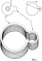
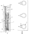
- a conventional RF ion guide 1 is shown in Fig. 1 .
- An RF voltage is applied to the electrodes forming the ion guide so that a single pseudo-potential valley or well 2 is generated or created within the ion guide 1.
- Ions are confined radially 3 within the ion guide 1.
- Ions are generally arranged to enter the ion guide 1 along the central longitudinal axis of the ion guide 1 and the ions generally also exit the ion guide 1 along the central longitudinal axis.
- An ion cloud 5 is confined within the ion guide 1 and the ions are generally confined close to the longitudinal axis by the pseudo-potential well 2.
- the conjoined ion guides comprise a first ion guide 7 and a second ion guide 8.
- the first ion guide 7 preferably has a larger radial cross section than the second ion guide 8.
- a diffuse source of gas and ions 9 is preferably initially constrained or confined within the first ion guide 7. Ions preferably initially flow through the first ion guide 7 for at least a portion of the axial length of the first ion guide 7.
- the ion cloud 9 preferably formed within the first ion guide 7 is radially-constrained but may be relatively diffuse.
- a potential difference is preferably applied or maintained between at least a section or substantially the whole of the first ion guide 7 and at least a section or substantially the whole of the second ion guide 8.
- ions are preferably caused to migrate from the first ion guide 7 to the second ion guide 8 across a relatively low amplitude pseudo-potential barrier.
- the pseudo-potential barrier is preferably located at the junction or boundary region between the first ion guide 7 and the second ion guide 8.
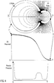
- Fig. 3 shows equipotential contours 11 and the DC potential surface 12 which result when a potential difference of 25 V is maintained between the first ion guide 7 and the second ion guide 8.
- the equipotential contours 11 and the potential surface 12 were derived using SIMION (RTM).
- Fig. 4 shows the same equipotential contours 11 as shown in Fig. 3 together with a plot showing how the DC potential varies in a radial direction along a line XY due to the applied potential difference.
- An RF-generated pseudo-potential along the line XY in the absence of a potential difference between the first ion guide 7 and the second ion guide 8 is also shown.
- the arrangement of electrodes and the potential difference which is preferably maintained between the electrodes of the two ion guides 7,8 preferably has the effect of causing ions from a relatively diffuse ion cloud 9 in the first ion guide 7 to be focussed into a substantially more compact ion cloud 10 in the second ion guide 8.
- the presence of background gas in the first ion guide 7 and the second ion guide 8 preferably causes the ion cloud to be cooled as it passes from the first ion guide 7 to the second ion guide 8.
- the pseudo-potential barrier preferably prevents ions being lost to the electrodes.
- Fig. 5 shows the results of an ion trajectory simulation based upon a model of two ion guides 7,8 each comprising a plurality of stacked-plate or ring electrodes.
- the electrodes preferably have an aperture through which ions are transmitted in use.
- Ion collisions with the background gas were simulated using a routine provided in SIMION (RTM).
- Nitrogen gas 14 was modelled as flowing along the length of the two ion guides 7,8 at a bulk flow rate of 300 m/s and at a pressure of 1 mbar.
- the first ion guide 7 was modelled as having an internal diameter of 15 mm and the second ion guide 8 was modelled as having an internal diameter of 5 mm.
- An RF voltage having an amplitude of 200 V pk-pk RF and a frequency of 3 MHz was modelled as being applied between adjacent electrodes 15 of the first and second ion guides 7,8.
- a radially confining pseudo-potential well is created within both ion guides 7,8.
- the overall length of the two ion guides 7,8 was modelled as being 75 mm.
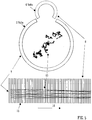
- Fig. 6 illustrates a repeat of the simulation shown and described above with reference to Fig. 5 except that an electric field 6 is now applied between the two ion guides 7,8.
- a potential difference of 25 V was maintained between the first ion guide 7 and the second ion guide 8.
- the effect of the electric field 6 is to direct or focus ions towards a plane along the central longitudinal axis of the second ion guide 8.
- the ions move from the first ion guide 7 across a pseudo-potential barrier between the two ion guides 7,8 and into the second ion guide 8.
- a relatively dense and compact ion cloud 10 is preferably formed from what was initially a relatively diffuse ion cloud 9.
- Fig. 6 shows various ion trajectories 13 as modelled by SIMION (RTM) for ions having mass to charge ratios of 500 entrained in a flow of nitrogen gas 14 at a pressure of 1 mbar.
- RTM SIMION
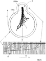
- Fig. 7 shows the results of a similar simulation to that described above with reference to Fig. 6 except that the ions had a common origin in the first ion guide 7 and differing mass to charge ratios.
- the ions were modelled as having mass to charge ratios of 100, 300, 500, 700, 900, 1100, 1300, 1500, 1700 and 1900.
- the ions were modelled as being entrained in a flow of nitrogen gas 14 at a pressure of 1 mbar.
- a 25 V potential difference was maintained between the first ion guide 7 and the second ion guide 8. It is apparent that all the ions were transferred from the first ion guide 7 to the second ion guide 8.
- Fig. 8 shows an arrangement wherein parallel conjoined ion guides 7,8 are arranged in the initial stage of a mass spectrometer.
- a mixture of gas and ions from an atmospheric pressure ion source 16 preferably passes through a sampling cone 17 into an initial vacuum chamber of a mass spectrometer which is exhausted by a pump 18.
- the first and second ion guides 7,8 are preferably arranged in the vacuum chamber with the aperture of the sampling cone 17 being preferably aligned with the central axis of the first ion guide 7.
- the first ion guide 7 is preferably arranged to have a larger diameter ion guiding region than the second ion guide 8.
- a diffuse cloud of ions 9 is preferably constrained within the first ion guide 7.
- the bulk of the gas flow preferably exits the vacuum chamber via a pumping port which is preferably aligned with the central axis of the first ion guide 7.
- a potential difference is preferably applied or maintained between the first ion guide 7 and the second ion guide 8.
- Ions are preferably transported from the first ion guide 7 to the second ion guide 8 and preferably follow ion trajections 13 similar to those shown in Fig. 8 .
- the ions preferably form a relatively compact ion cloud 10 within the second ion guide 8.
- the second ion guide 8 may continue or extend beyond the first ion guide 7 and may onwardly transport ions to a differential pumping aperture 19 which preferably leads to a subsequent vacuum stage. Ions may be arranged to pass through the differential pumping aperture 19 into a subsequent stage of the mass spectrometer. Ions may then be onwardly transmitted for subsequent analysis and detection.
- Fig. 8 also shows cross-sectional views of the first and second ion guides 7,8.
- Ions may be arranged to be substantially contained or confined within an upstream region or section 20 of the first ion guide 7 wherein the rings of the first ion guide 7 are closed. Ions may be transferred from the first ion guide 7 to the second ion guide 8 within an intermediate region or section 21 wherein the rings of the first 7 and second 8 ion guides are both open. Ions are substantially contained or confined within the second ion guide 8 within a downstream region or section 22 wherein the rings of the second ion guide 8 are closed.
- the conjoined ion guides 7,8 preferably allow ions to be moved or directed away from the bulk of the gas flow. The ions are also preferably brought into tighter ion confinement for optimum transmission through a differential pump aperture 19 into a subsequent vacuum stage.
- ion source may be operated at pressures below atmospheric pressure.
- Ions may be driven axially along at least a portion of the first ion guide 7 and/or along at least a portion of the second ion guide 8 by an electric field or travelling wave arrangement.
- one or more transient DC voltages or potentials or one or more transient DC voltage or potential waveforms may be applied to the electrodes forming the first ion guide 7 and/or to the electrodes forming the second ion guide 8 in order to urge or drive ions along at least a portion of the first ion guide 7 and/or along at least a portion of the second ion guide 8.
- the pseudo-potential barrier between the two conjoined ion guides 7,8 will preferably have an effective amplitude which is mass to charge ratio dependent.
- Appropriate RF voltages may be used and the potential difference maintained between the axes of the two ion guides 7,8 may be arranged so that ions may be mass selectivity transferred between the two ion guides 7,8.
- ions may be mass selectively or mass to charge ratio selectively transferred between the two ion guides 7,8.
- a DC voltage gradient maintained between the two ion guides 7,8 may be progressively varied or scanned.
- the amplitude and/or frequency of an AC or RF voltage applied to the electrodes of the two ion guides 7,8 maybe progressively varied or scanned.
- ions may be mass selectively transferred between the two ion guides 7,8 as a function of time and/or as a function of axial position along the ion guides 7,8.
- Fig. 9 shows an arrangement outside the scope of the invention, but useful for understanding the invention wherein two stacked plate ion guides are arranged to form a conjoined ion guide.
- Fig. 9 shows an end on view of two cylindrical ion guiding paths or ion guiding regions formed within a plurality of plate electrodes. Adjacent electrodes are preferably maintained at opposite phases of an RF voltage.
- the plate electrodes which form the first ion guide are preferably maintained at a first DC voltage DC1 as indicated in Fig. 9 .
- the plate electrodes which form the second ion guide are preferably maintained at a second voltage DC2 again as indicated in Fig. 9 .
- the second DC voltage DC2 is preferably different to the first DC voltage DC1.
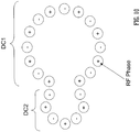
- Fig. 10 shows an embodiment wherein two rod set ion guides form a conjoined ion guide arrangement. Adjacent rods are preferably maintained at opposite phases of an RF voltage.
- the rods forming the two ion guides may or may not have the same diameter. According to the preferred embodiment all the rods forming the ion guiding arrangement preferably have the same or substantially the same diameter.
- the first ion guide comprises fifteen rod electrodes which are all preferably maintained at the same DC bias voltage DC1.
- the second ion guide comprises seven rod electrodes which are all preferably maintained at the same DC bias voltage DC2.
- the second DC voltage DC2 is preferably different to the first DC voltage DC1.
- a further embodiment is contemplated wherein more than two parallel ion guides may be provided.
- more than two parallel ion guides may be provided.
- at least 3, 4, 5, 6, 7, 8, 9 or 10 parallel ion guides or ion guiding regions may be provided. Ions may be switched between the plurality of parallel ion guides as desired.
Landscapes
- Chemical & Material Sciences (AREA)
- Analytical Chemistry (AREA)
- Other Investigation Or Analysis Of Materials By Electrical Means (AREA)
- Electron Tubes For Measurement (AREA)
- Electron Sources, Ion Sources (AREA)
Claims (12)
- Ionenführungsvorrichtung, Folgendes umfassend:zwei oder mehr parallele vereinigte Ionenführungen;wobei die zwei oder mehr parallelen vereinigten lonenführungen eine erste lonenführung (7) umfassen, die eine Stäbesatz-Ionenführung umfasst, die eine Vielzahl von Stabelektroden umfasst, und eine zweite lonenführung (8) umfasst, die eine Stäbesatz-Ionenführung umfasst, die eine Vielzahl von Stabelektroden umfasst;wobei die erste lonenführung (7) eine erste lonenführungsregion umfasst, die einen ersten Querschnittsbereich aufweist, und die zweite lonenführung (8) eine zweite lonenführungsregion umfasst, die einen zweiten Querschnittsbereich aufweist;wobei die Ionen radial zwischen der ersten lonenführung und der zweiten lonenführung über mindestens 1 %, 5 %, 10 %, 20 %, 30 %, 40 %, 50 %, 60 %, 70 %, 80 %, 90 %, 95% oder 100% der Länge der ersten lonenführung und/oder der zweiten lonenführung übertragen werden können; undwobei die erste lonenführung (7) eine erste zentrale Längsachse umfasst und die zweite lonenführung (8) eine zweite zentrale Längsachse umfasst und wobei die erste zentrale Längsachse nicht kollinear oder koaxial mit der zweiten zentralen Längsachse für 100% der Länge der ersten lonenführung und/ oder der zweiten lonenführung ist;dadurch gekennzeichnet, dass der erste und zweite Querschnittsbereich im Wesentlichen unterschiedlich sind.
- lonenführungsvorrichtung nach Anspruch 1, wobei die erste lonenführung und die zweite lonenführung über mindestens 1 %, 5 %, 10 %, 20 %, 30 %, 40 %, 50 %, 60 %, 70 %, 80 %, 90 %, 95 % oder 100 % der Länge der ersten lonenführung (7) und/oder der zweiten lonenführung (8) vereinigt sind.
- lonenführungsvorrichtung nach einem vorstehenden Anspruch, wobei ein Potentialunterschied in einem Betriebsmodus zwischen einem oder mehr der Vielzahl von Stabelektroden der ersten lonenführung und einer oder mehr der Vielzahl von Stabelektroden der zweiten lonenführung beibehalten wird, wobei der Potenzialunterschied ausgewählt ist aus der Gruppe bestehend aus: (i) ± 0-10 V; (ii) ± 10-20 V; (iii) ± 20-30 V; (iv) ± 30-40 V; (v) ± 40-50 V; (vi) ± 50-60 V; (vii) ± 60-70 V; (viii) ± 70-80 V; (ix) ± 80-90 V; (x) ± 90-100 V; (xi) ± 100-150 V; (xii) ± 150-200 V; (xiii) ± 200-250 V; (xiv) ± 250-300 V; (xv) ± 300-350 V; (xvi) ± 350-400 V; (xvii) ± 400-450 V; (xviii) ± 450-500 V; (xix) ± 500-550 V; (xx) ± 550-600 V; (xxi) ± 600-650 V; (xxii) ± 650-700 V; (xxiii) ± 700-750 V; (xxiv) ± 750-800 V; (xxv) ± 800-850 V; (xxvi) ± 850-900 V; (xxvii) ± 900-950 V; (xxviii) ± 950-1000 V und (xxix) > ± 1000 V.
- lonenführungsvorrichtung nach einem vorstehenden Anspruch, wobei eine erste lonenführung (7) eine erste zentrale Längsachse umfasst und eine zweite lonenführung (8) eine zweite zentrale Längsachse umfasst, und wobei die erste zentrale Längsachse über 100% der Länge der ersten lonenführung und/oder der zweiten lonenführung parallel zur zweiten zentralen Längsachse ist.
- lonenführungsvorrichtung nach einem vorstehenden Anspruch, wobei eine oder mehrere Überschneidungsregionen, -sektionen oder -kreuzungen zwischen der ersten lonenführung und der zweiten lonenführung angeordnet sind, in denen mindestens einige Ionen von der ersten lonenführung in die zweite lonenführung transferiert werden können oder bewirkt wird, dass diese transferiert werden.
- lonenführungsvorrichtung nach einem vorstehenden Anspruch, wobei das Verhältnis des ersten Querschnittsbereichs zum zweiten Querschnittsbereich ausgewählt ist aus der Gruppe bestehend aus: (i) < 0,1; (ii) 0,1-0,2; (iii) 0,2-0,3; (iv) 0,3-0,4; (v) 0,4-0,5; (vi) 0,5-0,6; (vii) 0,6-0,7; (viii) 0,7-0,8; (ix) 0,8-0,9; (x) 0,9-1,0; (xi) 1,0-1,1; (xii) 1,1-1,2; (xiii) 1,2-1,3; (xiv) 1,3-1,4; (xv) 1,4-1,5; (xvi) 1,5-1,6; (xvii) 1,6-1,7; (xviii) 1,7-1,8; (xix) 1,8-1,9; (xx) 1,9-2,0; (xxi) 2,0-2,5; (xxii) 2,5-3,0; (xxiii) 3,0-3,5; (xxiv) 3,5-4,0; (xxv) 4,0-4,5; (xxvi) 4,5-5,0; (xxvii) 5,0-6,0; (xxviii) 6,0-7,0; (xxix) 7,0-8,0; (xxx) 8,0-9,0; (xxxi) 9,0-10,0; (xxxii) >10,0.
- lonenführungsvorrichtung nach einem vorstehenden Anspruch, wobei die lonenführungsvorrichtung weiter eine Wechselspannungs- oder Hochfrequenzspannungsversorgung zum Anlegen einer Wechselspannung oder einer Hochfrequenzspannung an mindestens einige der Vielzahl von Stabelektroden der ersten und/oder zweiten lonenführung umfasst, wobei die Wechselspannung oder Hochfrequenzspannung einen oder mehrere radiale Pseudopotentialtöpfe generiert, die dazu dienen, Ionen radial innerhalb der ersten Ionenführung und/oder der zweiten lonenführung zu beschränken.
- Massenspektrometer, eine lonenführungsvorrichtung nach einem vorstehenden Anspruch umfassend.
- Massenspektrometer nach Anspruch 8, weiter umfassend eine lonenquelle, die stromaufwärts der ersten lonenführung und/ oder zweiten lonenführung angeordnet ist, wobei die lonenquelle eine Elektrosprühionisierungs- ("ESI")-Ionenquelle ist.
- Massenspektrometer nach Anspruch 8 oder 9, weiter umfassend einen Massenanalysator, ausgewählt aus der Gruppe bestehend aus: (i) einem Quadrupol-Massenanalysator; (ii) einem 2D oder linearen Quadrupol-Massenanalysator; (iii) einem Paul oder 3D Quadrupol-Massenanalysator; (iv) einem Penning-Fallen-Massenanalysator; (v) einem Ionenfallen-Massenanalysator; (vi) einem Magnetsektor-Massenanalysator; (vii) Ionen-Zyklotronresonanz- ("ICR")-Massenanalysator; (viii) einem Fourier-Transformations-Ionenzyklotronresonanz- ("FTICR")-Massenanalysator; (ix) einem elektrostatischen oder Orbifallen-Massenanalysator; (x) einem Fourier-Transformations-Elektrostatik- oder Orbifallen-Massenanalysator; (xi) Fourier-Transformations-Massenanalysator; (xii) einem Flugzeit-Massenanalysator; (xiii) einem Orthogonalbeschleunigungs-Flugzeit-Massenanalysator; und (xiv) einem Linearbeschleunigungs-Flugzeit-Massenanalysator.
- Verfahren zum Führen von Ionen, umfassend das Führen von Ionen entlang einer lonenführungsvorrichtung nach einem der Ansprüche 1-7.
- Verfahren für Massenspektrometrie, umfassend da Verfahren nach Anspruch 11.
Applications Claiming Priority (5)
| Application Number | Priority Date | Filing Date | Title |
|---|---|---|---|
| GBGB0718468.2A GB0718468D0 (en) | 2007-09-21 | 2007-09-21 | Mass spectrometer |
| US98810707P | 2007-11-15 | 2007-11-15 | |
| EP08806353.2A EP2191493B1 (de) | 2007-09-21 | 2008-09-22 | Ionenführungseinrichtung |
| EP14199030.9A EP2866248B1 (de) | 2007-09-21 | 2008-09-22 | Ionenführungsvorrichtung |
| PCT/GB2008/003198 WO2009037483A2 (en) | 2007-09-21 | 2008-09-22 | Ion guiding device |
Related Parent Applications (3)
| Application Number | Title | Priority Date | Filing Date |
|---|---|---|---|
| EP08806353.2A Division EP2191493B1 (de) | 2007-09-21 | 2008-09-22 | Ionenführungseinrichtung |
| EP14199030.9A Division-Into EP2866248B1 (de) | 2007-09-21 | 2008-09-22 | Ionenführungsvorrichtung |
| EP14199030.9A Division EP2866248B1 (de) | 2007-09-21 | 2008-09-22 | Ionenführungsvorrichtung |
Publications (2)
| Publication Number | Publication Date |
|---|---|
| EP3640970A1 EP3640970A1 (de) | 2020-04-22 |
| EP3640970B1 true EP3640970B1 (de) | 2021-08-04 |
Family
ID=38670316
Family Applications (3)
| Application Number | Title | Priority Date | Filing Date |
|---|---|---|---|
| EP08806353.2A Active EP2191493B1 (de) | 2007-09-21 | 2008-09-22 | Ionenführungseinrichtung |
| EP14199030.9A Active EP2866248B1 (de) | 2007-09-21 | 2008-09-22 | Ionenführungsvorrichtung |
| EP19209836.6A Active EP3640970B1 (de) | 2007-09-21 | 2008-09-22 | Ionenführungsvorrichtung |
Family Applications Before (2)
| Application Number | Title | Priority Date | Filing Date |
|---|---|---|---|
| EP08806353.2A Active EP2191493B1 (de) | 2007-09-21 | 2008-09-22 | Ionenführungseinrichtung |
| EP14199030.9A Active EP2866248B1 (de) | 2007-09-21 | 2008-09-22 | Ionenführungsvorrichtung |
Country Status (7)
| Country | Link |
|---|---|
| US (4) | US8581181B2 (de) |
| EP (3) | EP2191493B1 (de) |
| JP (2) | JP5005094B2 (de) |
| CN (1) | CN101868843B (de) |
| CA (1) | CA2700316C (de) |
| GB (3) | GB0718468D0 (de) |
| WO (1) | WO2009037483A2 (de) |
Families Citing this family (84)
| Publication number | Priority date | Publication date | Assignee | Title |
|---|---|---|---|---|
| GB0718468D0 (en) | 2007-09-21 | 2007-10-31 | Micromass Ltd | Mass spectrometer |
| GB2477832B (en) * | 2008-09-18 | 2013-05-01 | Micromass Ltd | Ion guide array |
| GB0817115D0 (en) | 2008-09-18 | 2008-10-29 | Micromass Ltd | Mass spectrometer |
| US8309936B2 (en) * | 2009-02-27 | 2012-11-13 | Trustees Of Columbia University In The City Of New York | Ion deflector for two-dimensional control of ion beam cross sectional spread |
| GB201021360D0 (en) * | 2010-12-16 | 2011-01-26 | Thermo Fisher Scient Bremen Gmbh | Apparatus and methods for ion mobility spectrometry |
| GB201104220D0 (en) * | 2011-03-14 | 2011-04-27 | Micromass Ltd | Ion guide with orthogonal sampling |
| US8314385B2 (en) * | 2011-04-19 | 2012-11-20 | Bruker Daltonics, Inc. | System and method to eliminate radio frequency coupling between components in mass spectrometers |
| CN107658203B (zh) | 2011-05-05 | 2020-04-14 | 岛津研究实验室(欧洲)有限公司 | 操纵带电粒子的装置 |
| GB201111560D0 (en) * | 2011-07-06 | 2011-08-24 | Micromass Ltd | Photo-dissociation of proteins and peptides in a mass spectrometer |
| GB201111568D0 (en) * | 2011-07-06 | 2011-08-24 | Micromass Ltd | Apparatus and method of mass spectrometry |
| GB201111569D0 (en) * | 2011-07-06 | 2011-08-24 | Micromass Ltd | Apparatus and method of mass spectrometry |
| WO2013140139A2 (en) * | 2012-03-23 | 2013-09-26 | Micromass Uk Limited | Ion guide construction method |
| CN103515183B (zh) * | 2012-06-20 | 2017-06-23 | 株式会社岛津制作所 | 离子导引装置和离子导引方法 |
| CN102778498B (zh) * | 2012-07-11 | 2014-10-29 | 复旦大学 | 用于质谱和光谱分析的高分辨离子选择性光解离装置与方法 |
| EP2907155A4 (de) * | 2012-10-12 | 2016-07-13 | Dh Technologies Dev Pte Ltd | Ionenführung für massenspektrometrie |
| US8704193B1 (en) | 2012-11-16 | 2014-04-22 | Thermo Fisher Scientific (Bremen) Gmbh | RF transformer |
| US9812311B2 (en) | 2013-04-08 | 2017-11-07 | Battelle Memorial Institute | Ion manipulation method and device |
| US8835839B1 (en) | 2013-04-08 | 2014-09-16 | Battelle Memorial Institute | Ion manipulation device |
| US10128092B2 (en) | 2013-05-31 | 2018-11-13 | Micromass Uk Limited | Compact mass spectrometer |
| US10090138B2 (en) | 2013-05-31 | 2018-10-02 | Micromass Uk Limited | Compact mass spectrometer |
| US9530631B2 (en) | 2013-05-31 | 2016-12-27 | Micromass Uk Limited | Compact mass spectrometer |
| US10096458B2 (en) | 2013-05-31 | 2018-10-09 | Micromass Uk Limited | Compact mass spectrometer |
| JP2016526168A (ja) | 2013-06-07 | 2016-09-01 | マイクロマス ユーケー リミテッド | イオン信号を較正する方法 |
| CN104465296B (zh) * | 2013-09-13 | 2017-10-31 | 岛津分析技术研发(上海)有限公司 | 离子传输装置以及离子传输方法 |
| US8907272B1 (en) | 2013-10-04 | 2014-12-09 | Thermo Finnigan Llc | Radio frequency device to separate ions from gas stream and method thereof |
| CN105849857A (zh) * | 2013-12-31 | 2016-08-10 | Dh科技发展私人贸易有限公司 | 用于质谱分析法的离子导向件 |
| US9063086B1 (en) | 2014-02-12 | 2015-06-23 | Battelle Memorial Institute | Method and apparatus for compressing ions |
| US9558925B2 (en) | 2014-04-18 | 2017-01-31 | Battelle Memorial Institute | Device for separating non-ions from ions |
| US9773656B2 (en) | 2014-05-14 | 2017-09-26 | Shimadzu Corporation | Ion transport apparatus and mass spectrometer using the same |
| CN104538278B (zh) * | 2014-12-16 | 2017-01-04 | 中国科学院长春光学精密机械与物理研究所 | 一种离子迁移发生装置及其控制方法 |
| US9330894B1 (en) | 2015-02-03 | 2016-05-03 | Thermo Finnigan Llc | Ion transfer method and device |
| JP6458128B2 (ja) * | 2015-02-23 | 2019-01-23 | 株式会社日立ハイテクノロジーズ | イオンガイド及びそれを用いた質量分析装置 |
| GB2583311B (en) * | 2015-02-23 | 2021-01-27 | Hitachi High Tech Corp | Ion guide and mass spectrometer using same |
| US9761427B2 (en) | 2015-04-29 | 2017-09-12 | Thermo Finnigan Llc | System for transferring ions in a mass spectrometer |
| GB2538075B (en) | 2015-05-05 | 2019-05-15 | Thermo Fisher Scient Bremen Gmbh | Method and apparatus for injection of ions into an electrostatic ion trap |
| US9704701B2 (en) | 2015-09-11 | 2017-07-11 | Battelle Memorial Institute | Method and device for ion mobility separations |
| GB201517068D0 (en) | 2015-09-28 | 2015-11-11 | Micromass Ltd | Ion guide |
| US10317364B2 (en) | 2015-10-07 | 2019-06-11 | Battelle Memorial Institute | Method and apparatus for ion mobility separations utilizing alternating current waveforms |
| CN107305833B (zh) | 2016-04-25 | 2019-05-28 | 株式会社岛津制作所 | 离子光学装置 |
| US10018592B2 (en) | 2016-05-17 | 2018-07-10 | Battelle Memorial Institute | Method and apparatus for spatial compression and increased mobility resolution of ions |
| GB201609243D0 (en) * | 2016-05-25 | 2016-07-06 | Micromass Ltd | Efficient ion tapping |
| GB2566891B (en) * | 2016-08-19 | 2021-09-01 | Hitachi High Tech Corp | Ion analysis device |
| US10224194B2 (en) | 2016-09-08 | 2019-03-05 | Battelle Memorial Institute | Device to manipulate ions of same or different polarities |
| US9899181B1 (en) * | 2017-01-12 | 2018-02-20 | Fei Company | Collision ionization ion source |
| CN108807132B (zh) | 2017-04-28 | 2021-06-25 | 株式会社岛津制作所 | 一种离子导引装置及导引方法 |
| DE112018004182T5 (de) | 2017-08-16 | 2020-05-07 | Battelle Memorial Institute | Verfahren und Systeme zur Ionen-Manipulation |
| US10692710B2 (en) | 2017-08-16 | 2020-06-23 | Battelle Memorial Institute | Frequency modulated radio frequency electric field for ion manipulation |
| WO2019070324A1 (en) | 2017-10-04 | 2019-04-11 | Battelle Memorial Institute | METHODS AND SYSTEMS FOR INTEGRATING ION HANDLING DEVICES |
| US10236168B1 (en) | 2017-11-21 | 2019-03-19 | Thermo Finnigan Llc | Ion transfer method and device |
| US10332723B1 (en) | 2017-12-20 | 2019-06-25 | Battelle Memorial Institute | Ion focusing device |
| GB2575770B (en) * | 2018-05-17 | 2022-06-22 | Thermo Fisher Scient Bremen Gmbh | Ion guide |
| GB2575342B (en) | 2018-05-17 | 2022-08-10 | Thermo Fisher Scient Bremen Gmbh | Ion guide |
| GB201808893D0 (en) | 2018-05-31 | 2018-07-18 | Micromass Ltd | Bench-top time of flight mass spectrometer |
| GB201808912D0 (en) | 2018-05-31 | 2018-07-18 | Micromass Ltd | Bench-top time of flight mass spectrometer |
| US11367607B2 (en) | 2018-05-31 | 2022-06-21 | Micromass Uk Limited | Mass spectrometer |
| WO2019229463A1 (en) | 2018-05-31 | 2019-12-05 | Micromass Uk Limited | Mass spectrometer having fragmentation region |
| GB201808890D0 (en) | 2018-05-31 | 2018-07-18 | Micromass Ltd | Bench-top time of flight mass spectrometer |
| GB201808894D0 (en) | 2018-05-31 | 2018-07-18 | Micromass Ltd | Mass spectrometer |
| GB201808949D0 (en) | 2018-05-31 | 2018-07-18 | Micromass Ltd | Bench-top time of flight mass spectrometer |
| GB201808942D0 (en) * | 2018-05-31 | 2018-07-18 | Micromass Ltd | Bench-top time of flight mass spectrometer |
| GB201808932D0 (en) | 2018-05-31 | 2018-07-18 | Micromass Ltd | Bench-top time of flight mass spectrometer |
| GB201808892D0 (en) | 2018-05-31 | 2018-07-18 | Micromass Ltd | Mass spectrometer |
| GB201808936D0 (en) | 2018-05-31 | 2018-07-18 | Micromass Ltd | Bench-top time of flight mass spectrometer |
| US10720315B2 (en) | 2018-06-05 | 2020-07-21 | Trace Matters Scientific Llc | Reconfigurable sequentially-packed ion (SPION) transfer device |
| US10840077B2 (en) | 2018-06-05 | 2020-11-17 | Trace Matters Scientific Llc | Reconfigureable sequentially-packed ion (SPION) transfer device |
| US12089932B2 (en) | 2018-06-05 | 2024-09-17 | Trace Matters Scientific Llc | Apparatus, system, and method for transferring ions |
| US11219393B2 (en) | 2018-07-12 | 2022-01-11 | Trace Matters Scientific Llc | Mass spectrometry system and method for analyzing biological samples |
| US10460920B1 (en) | 2018-06-26 | 2019-10-29 | Battelle Memorial Institute | Flexible ion conduit |
| US10651025B1 (en) | 2018-12-21 | 2020-05-12 | Thermo Finnigan Llc | Orthogonal-flow ion trap array |
| WO2021176986A1 (ja) | 2020-03-05 | 2021-09-10 | 株式会社日立ハイテク | 質量分析装置 |
| JP7073459B2 (ja) * | 2020-09-02 | 2022-05-23 | 株式会社日立ハイテク | イオンガイド及びそれを用いた質量分析装置 |
| CN114334599B (zh) | 2020-09-29 | 2024-12-06 | 株式会社岛津制作所 | 离子导引装置及离子导引方法 |
| WO2022180550A1 (en) * | 2021-02-25 | 2022-09-01 | Dh Technologies Development Pte. Ltd. | Bent pcb ion guide for reduction of contamination and noise |
| US12125692B2 (en) | 2021-06-11 | 2024-10-22 | Thermo Fisher Scientific (Bremen) Gmbh | Complemented ion funnel for mass spectrometer |
| US12431344B2 (en) | 2021-06-11 | 2025-09-30 | Thermo Finnigan Llc | Complemented ion funnel for mass spectrometer |
| GB2620377B (en) | 2022-06-29 | 2025-03-19 | Thermo Fisher Scient Bremen Gmbh | Switchable-path ion guide |
| GB2622408B (en) | 2022-09-15 | 2024-12-11 | Thermo Fisher Scient Bremen Gmbh | Ion guide |
| GB2626523A (en) * | 2022-11-15 | 2024-07-31 | Thermo Fisher Scient Bremen Gmbh | Collisional activation in ion guides |
| GB2624389A (en) | 2022-11-15 | 2024-05-22 | Thermo Fisher Scient Bremen Gmbh | Ion guide |
| US20240222106A1 (en) * | 2022-12-29 | 2024-07-04 | Thermo Finnigan Llc | Apparatus and Method for Ion Separation |
| GB2637007B (en) | 2024-01-03 | 2026-03-18 | Thermo Fisher Scient Bremen Gmbh | Methods of mass spectrometry, a mass spectrometer and computer software |
| GB2637009A (en) | 2024-01-03 | 2025-07-09 | Thermo Fisher Scient Bremen Gmbh | A method of mass spectrometry, a method of manipulating ions using an ion store, an ion store, a mass spectrometer and computer software |
| GB2637008A (en) | 2024-01-03 | 2025-07-09 | Thermo Fisher Scient Bremen Gmbh | An ion guide, a method of manipulating ions using an ion guide, a method of mass spectrometry, a mass spectrometer and computer software |
| WO2025174439A1 (en) * | 2024-02-16 | 2025-08-21 | Agilent Technologies, Inc. | Ion guide including orthogonal merging pseudo-potential wells |
Family Cites Families (31)
| Publication number | Priority date | Publication date | Assignee | Title |
|---|---|---|---|---|
| GB8717118D0 (en) | 1987-07-20 | 1987-08-26 | Wiggins Teape Group Ltd | Determining propensity of paper/board to dust |
| JP4097695B2 (ja) | 1995-06-13 | 2008-06-11 | マッシヴリー パラレル インストゥルメンツ インコーポレイテッド | 平行イオン光学素子および高電流低エネルギイオンビーム装置 |
| US5576540A (en) | 1995-08-11 | 1996-11-19 | Mds Health Group Limited | Mass spectrometer with radial ejection |
| JP3663716B2 (ja) * | 1996-02-05 | 2005-06-22 | 株式会社日立製作所 | 四重極イオン蓄積リング |
| JPH1097838A (ja) | 1996-07-30 | 1998-04-14 | Yokogawa Analytical Syst Kk | 誘導結合プラズマ質量分析装置 |
| US6753523B1 (en) * | 1998-01-23 | 2004-06-22 | Analytica Of Branford, Inc. | Mass spectrometry with multipole ion guides |
| GB2389452B (en) | 2001-12-06 | 2006-05-10 | Bruker Daltonik Gmbh | Ion-guide |
| US6891157B2 (en) | 2002-05-31 | 2005-05-10 | Micromass Uk Limited | Mass spectrometer |
| US6838666B2 (en) * | 2003-01-10 | 2005-01-04 | Purdue Research Foundation | Rectilinear ion trap and mass analyzer system and method |
| GB2418775B (en) * | 2003-03-19 | 2008-10-15 | Thermo Finnigan Llc | Obtaining tandem mass spectrometry data for multiple parent ions in an ion population |
| US6979816B2 (en) | 2003-03-25 | 2005-12-27 | Battelle Memorial Institute | Multi-source ion funnel |
| US7217919B2 (en) * | 2004-11-02 | 2007-05-15 | Analytica Of Branford, Inc. | Method and apparatus for multiplexing plural ion beams to a mass spectrometer |
| CN1326191C (zh) * | 2004-06-04 | 2007-07-11 | 复旦大学 | 用印刷电路板构建的离子阱质量分析仪 |
| DE102004028419B4 (de) | 2004-06-11 | 2011-06-22 | Bruker Daltonik GmbH, 28359 | Massenspektrometer und Reaktionszelle für Ionen-Ionen-Reaktionen |
| DE102004028638B4 (de) * | 2004-06-15 | 2010-02-04 | Bruker Daltonik Gmbh | Speicher für molekularen Detektor |
| GB2415541B (en) | 2004-06-21 | 2009-09-23 | Thermo Finnigan Llc | RF power supply for a mass spectrometer |
| GB2427067B (en) | 2005-03-29 | 2010-02-24 | Thermo Finnigan Llc | Improvements relating to ion trapping |
| US7358488B2 (en) | 2005-09-12 | 2008-04-15 | Mds Inc. | Mass spectrometer multiple device interface for parallel configuration of multiple devices |
| GB0522327D0 (en) | 2005-11-01 | 2005-12-07 | Micromass Ltd | Mass spectrometer |
| WO2007062498A1 (en) | 2005-11-30 | 2007-06-07 | Mds Analytical Technologies, A Business Unit Of Mds Inc., Doing Business Through Its Sciex Division | Method and apparatus for mass selective axial transport using pulsed axial field |
| GB0524972D0 (en) | 2005-12-07 | 2006-01-18 | Micromass Ltd | Mass spectrometer |
| GB0526245D0 (en) * | 2005-12-22 | 2006-02-01 | Shimadzu Res Lab Europe Ltd | A mass spectrometer using a dynamic pressure ion source |
| JP5290960B2 (ja) | 2006-04-28 | 2013-09-18 | マイクロマス ユーケー リミテッド | 質量分析計 |
| GB0608470D0 (en) | 2006-04-28 | 2006-06-07 | Micromass Ltd | Mass spectrometer |
| US7459678B2 (en) | 2006-05-12 | 2008-12-02 | Thermo Finnigan Llc | Switchable branched ion guide |
| US20080067349A1 (en) * | 2006-05-26 | 2008-03-20 | Science & Engineering Services, Inc. | Multi-channel time-of-flight mass spectrometer |
| DE102006040000B4 (de) * | 2006-08-25 | 2010-10-28 | Bruker Daltonik Gmbh | Speicherbatterie für Ionen |
| US20080087813A1 (en) * | 2006-10-13 | 2008-04-17 | Agilent Technologies, Inc. | Multi source, multi path mass spectrometer |
| US7868289B2 (en) * | 2007-04-30 | 2011-01-11 | Ionics Mass Spectrometry Group Inc. | Mass spectrometer ion guide providing axial field, and method |
| GB0718468D0 (en) * | 2007-09-21 | 2007-10-31 | Micromass Ltd | Mass spectrometer |
| GB0817115D0 (en) * | 2008-09-18 | 2008-10-29 | Micromass Ltd | Mass spectrometer |
-
2007
- 2007-09-21 GB GBGB0718468.2A patent/GB0718468D0/en not_active Ceased
-
2008
- 2008-09-22 US US12/679,139 patent/US8581181B2/en active Active
- 2008-09-22 EP EP08806353.2A patent/EP2191493B1/de active Active
- 2008-09-22 EP EP14199030.9A patent/EP2866248B1/de active Active
- 2008-09-22 CN CN2008801156486A patent/CN101868843B/zh active Active
- 2008-09-22 JP JP2010525435A patent/JP5005094B2/ja active Active
- 2008-09-22 EP EP19209836.6A patent/EP3640970B1/de active Active
- 2008-09-22 CA CA2700316A patent/CA2700316C/en active Active
- 2008-09-22 GB GB1009452.2A patent/GB2468077B/en active Active
- 2008-09-22 GB GB0817358A patent/GB2455171B/en active Active
- 2008-09-22 WO PCT/GB2008/003198 patent/WO2009037483A2/en not_active Ceased
-
2011
- 2011-09-14 JP JP2011200315A patent/JP5552671B2/ja active Active
-
2013
- 2013-03-08 US US13/789,887 patent/US8581182B2/en active Active
- 2013-11-11 US US14/076,627 patent/US9035241B2/en active Active
-
2015
- 2015-05-04 US US14/703,301 patent/US9373489B2/en active Active
Non-Patent Citations (1)
| Title |
|---|
| None * |
Also Published As
| Publication number | Publication date |
|---|---|
| EP2191493B1 (de) | 2015-01-07 |
| JP5552671B2 (ja) | 2014-07-16 |
| WO2009037483A2 (en) | 2009-03-26 |
| GB2468077B (en) | 2012-02-22 |
| EP2866248B1 (de) | 2020-01-08 |
| US9035241B2 (en) | 2015-05-19 |
| CA2700316C (en) | 2016-07-26 |
| WO2009037483A3 (en) | 2009-11-19 |
| CN101868843B (zh) | 2012-07-18 |
| GB0718468D0 (en) | 2007-10-31 |
| HK1146329A1 (en) | 2011-05-27 |
| US8581182B2 (en) | 2013-11-12 |
| JP5005094B2 (ja) | 2012-08-22 |
| JP2010541125A (ja) | 2010-12-24 |
| US8581181B2 (en) | 2013-11-12 |
| GB201009452D0 (en) | 2010-07-21 |
| CA2700316A1 (en) | 2009-03-26 |
| EP2866248A1 (de) | 2015-04-29 |
| GB2455171A (en) | 2009-06-03 |
| EP3640970A1 (de) | 2020-04-22 |
| GB2455171B (en) | 2010-08-11 |
| US20140131565A1 (en) | 2014-05-15 |
| US20150235832A1 (en) | 2015-08-20 |
| US20110049357A1 (en) | 2011-03-03 |
| EP2191493A2 (de) | 2010-06-02 |
| JP2012028336A (ja) | 2012-02-09 |
| GB0817358D0 (en) | 2008-10-29 |
| US20130214149A1 (en) | 2013-08-22 |
| US9373489B2 (en) | 2016-06-21 |
| CN101868843A (zh) | 2010-10-20 |
| GB2468077A (en) | 2010-08-25 |
Similar Documents
| Publication | Publication Date | Title |
|---|---|---|
| EP3640970B1 (de) | Ionenführungsvorrichtung | |
| US9786479B2 (en) | Mass spectrometer device and method using scanned phase applied potentials in ion guidance | |
| EP2013895B1 (de) | Massenspektrometer | |
| US9865442B2 (en) | Curved ion guide with non mass to charge ratio dependent confinement | |
| US10304673B2 (en) | Ion guide | |
| HK1146329B (en) | Ion guiding device |
Legal Events
| Date | Code | Title | Description |
|---|---|---|---|
| PUAI | Public reference made under article 153(3) epc to a published international application that has entered the european phase |
Free format text: ORIGINAL CODE: 0009012 |
|
| STAA | Information on the status of an ep patent application or granted ep patent |
Free format text: STATUS: THE APPLICATION HAS BEEN PUBLISHED |
|
| AC | Divisional application: reference to earlier application |
Ref document number: 2866248 Country of ref document: EP Kind code of ref document: P Ref document number: 2191493 Country of ref document: EP Kind code of ref document: P |
|
| AK | Designated contracting states |
Kind code of ref document: A1 Designated state(s): AT BE BG CH CY CZ DE DK EE ES FI FR GB GR HR HU IE IS IT LI LT LU LV MC MT NL NO PL PT RO SE SI SK TR |
|
| STAA | Information on the status of an ep patent application or granted ep patent |
Free format text: STATUS: REQUEST FOR EXAMINATION WAS MADE |
|
| 17P | Request for examination filed |
Effective date: 20200922 |
|
| RBV | Designated contracting states (corrected) |
Designated state(s): AT BE BG CH CY CZ DE DK EE ES FI FR GB GR HR HU IE IS IT LI LT LU LV MC MT NL NO PL PT RO SE SI SK TR |
|
| GRAP | Despatch of communication of intention to grant a patent |
Free format text: ORIGINAL CODE: EPIDOSNIGR1 |
|
| STAA | Information on the status of an ep patent application or granted ep patent |
Free format text: STATUS: GRANT OF PATENT IS INTENDED |
|
| INTG | Intention to grant announced |
Effective date: 20201105 |
|
| GRAJ | Information related to disapproval of communication of intention to grant by the applicant or resumption of examination proceedings by the epo deleted |
Free format text: ORIGINAL CODE: EPIDOSDIGR1 |
|
| STAA | Information on the status of an ep patent application or granted ep patent |
Free format text: STATUS: REQUEST FOR EXAMINATION WAS MADE |
|
| GRAP | Despatch of communication of intention to grant a patent |
Free format text: ORIGINAL CODE: EPIDOSNIGR1 |
|
| STAA | Information on the status of an ep patent application or granted ep patent |
Free format text: STATUS: GRANT OF PATENT IS INTENDED |
|
| INTC | Intention to grant announced (deleted) | ||
| INTG | Intention to grant announced |
Effective date: 20210323 |
|
| GRAS | Grant fee paid |
Free format text: ORIGINAL CODE: EPIDOSNIGR3 |
|
| GRAA | (expected) grant |
Free format text: ORIGINAL CODE: 0009210 |
|
| STAA | Information on the status of an ep patent application or granted ep patent |
Free format text: STATUS: THE PATENT HAS BEEN GRANTED |
|
| AC | Divisional application: reference to earlier application |
Ref document number: 2866248 Country of ref document: EP Kind code of ref document: P Ref document number: 2191493 Country of ref document: EP Kind code of ref document: P |
|
| AK | Designated contracting states |
Kind code of ref document: B1 Designated state(s): AT BE BG CH CY CZ DE DK EE ES FI FR GB GR HR HU IE IS IT LI LT LU LV MC MT NL NO PL PT RO SE SI SK TR |
|
| REG | Reference to a national code |
Ref country code: GB Ref legal event code: FG4D |
|
| REG | Reference to a national code |
Ref country code: AT Ref legal event code: REF Ref document number: 1417844 Country of ref document: AT Kind code of ref document: T Effective date: 20210815 |
|
| REG | Reference to a national code |
Ref country code: CH Ref legal event code: EP |
|
| REG | Reference to a national code |
Ref country code: DE Ref legal event code: R096 Ref document number: 602008064153 Country of ref document: DE |
|
| REG | Reference to a national code |
Ref country code: IE Ref legal event code: FG4D |
|
| REG | Reference to a national code |
Ref country code: LT Ref legal event code: MG9D |
|
| REG | Reference to a national code |
Ref country code: NL Ref legal event code: MP Effective date: 20210804 |
|
| REG | Reference to a national code |
Ref country code: AT Ref legal event code: MK05 Ref document number: 1417844 Country of ref document: AT Kind code of ref document: T Effective date: 20210804 |
|
| PG25 | Lapsed in a contracting state [announced via postgrant information from national office to epo] |
Ref country code: ES Free format text: LAPSE BECAUSE OF FAILURE TO SUBMIT A TRANSLATION OF THE DESCRIPTION OR TO PAY THE FEE WITHIN THE PRESCRIBED TIME-LIMIT Effective date: 20210804 Ref country code: SE Free format text: LAPSE BECAUSE OF FAILURE TO SUBMIT A TRANSLATION OF THE DESCRIPTION OR TO PAY THE FEE WITHIN THE PRESCRIBED TIME-LIMIT Effective date: 20210804 Ref country code: LT Free format text: LAPSE BECAUSE OF FAILURE TO SUBMIT A TRANSLATION OF THE DESCRIPTION OR TO PAY THE FEE WITHIN THE PRESCRIBED TIME-LIMIT Effective date: 20210804 Ref country code: AT Free format text: LAPSE BECAUSE OF FAILURE TO SUBMIT A TRANSLATION OF THE DESCRIPTION OR TO PAY THE FEE WITHIN THE PRESCRIBED TIME-LIMIT Effective date: 20210804 Ref country code: BG Free format text: LAPSE BECAUSE OF FAILURE TO SUBMIT A TRANSLATION OF THE DESCRIPTION OR TO PAY THE FEE WITHIN THE PRESCRIBED TIME-LIMIT Effective date: 20211104 Ref country code: HR Free format text: LAPSE BECAUSE OF FAILURE TO SUBMIT A TRANSLATION OF THE DESCRIPTION OR TO PAY THE FEE WITHIN THE PRESCRIBED TIME-LIMIT Effective date: 20210804 Ref country code: FI Free format text: LAPSE BECAUSE OF FAILURE TO SUBMIT A TRANSLATION OF THE DESCRIPTION OR TO PAY THE FEE WITHIN THE PRESCRIBED TIME-LIMIT Effective date: 20210804 Ref country code: NO Free format text: LAPSE BECAUSE OF FAILURE TO SUBMIT A TRANSLATION OF THE DESCRIPTION OR TO PAY THE FEE WITHIN THE PRESCRIBED TIME-LIMIT Effective date: 20211104 Ref country code: PT Free format text: LAPSE BECAUSE OF FAILURE TO SUBMIT A TRANSLATION OF THE DESCRIPTION OR TO PAY THE FEE WITHIN THE PRESCRIBED TIME-LIMIT Effective date: 20211206 |
|
| PG25 | Lapsed in a contracting state [announced via postgrant information from national office to epo] |
Ref country code: PL Free format text: LAPSE BECAUSE OF FAILURE TO SUBMIT A TRANSLATION OF THE DESCRIPTION OR TO PAY THE FEE WITHIN THE PRESCRIBED TIME-LIMIT Effective date: 20210804 Ref country code: LV Free format text: LAPSE BECAUSE OF FAILURE TO SUBMIT A TRANSLATION OF THE DESCRIPTION OR TO PAY THE FEE WITHIN THE PRESCRIBED TIME-LIMIT Effective date: 20210804 Ref country code: GR Free format text: LAPSE BECAUSE OF FAILURE TO SUBMIT A TRANSLATION OF THE DESCRIPTION OR TO PAY THE FEE WITHIN THE PRESCRIBED TIME-LIMIT Effective date: 20211105 |
|
| PG25 | Lapsed in a contracting state [announced via postgrant information from national office to epo] |
Ref country code: NL Free format text: LAPSE BECAUSE OF FAILURE TO SUBMIT A TRANSLATION OF THE DESCRIPTION OR TO PAY THE FEE WITHIN THE PRESCRIBED TIME-LIMIT Effective date: 20210804 |
|
| PG25 | Lapsed in a contracting state [announced via postgrant information from national office to epo] |
Ref country code: DK Free format text: LAPSE BECAUSE OF FAILURE TO SUBMIT A TRANSLATION OF THE DESCRIPTION OR TO PAY THE FEE WITHIN THE PRESCRIBED TIME-LIMIT Effective date: 20210804 |
|
| REG | Reference to a national code |
Ref country code: DE Ref legal event code: R097 Ref document number: 602008064153 Country of ref document: DE |
|
| REG | Reference to a national code |
Ref country code: CH Ref legal event code: PL |
|
| REG | Reference to a national code |
Ref country code: BE Ref legal event code: MM Effective date: 20210930 |
|
| PG25 | Lapsed in a contracting state [announced via postgrant information from national office to epo] |
Ref country code: SK Free format text: LAPSE BECAUSE OF FAILURE TO SUBMIT A TRANSLATION OF THE DESCRIPTION OR TO PAY THE FEE WITHIN THE PRESCRIBED TIME-LIMIT Effective date: 20210804 Ref country code: RO Free format text: LAPSE BECAUSE OF FAILURE TO SUBMIT A TRANSLATION OF THE DESCRIPTION OR TO PAY THE FEE WITHIN THE PRESCRIBED TIME-LIMIT Effective date: 20210804 Ref country code: MC Free format text: LAPSE BECAUSE OF FAILURE TO SUBMIT A TRANSLATION OF THE DESCRIPTION OR TO PAY THE FEE WITHIN THE PRESCRIBED TIME-LIMIT Effective date: 20210804 Ref country code: EE Free format text: LAPSE BECAUSE OF FAILURE TO SUBMIT A TRANSLATION OF THE DESCRIPTION OR TO PAY THE FEE WITHIN THE PRESCRIBED TIME-LIMIT Effective date: 20210804 Ref country code: CZ Free format text: LAPSE BECAUSE OF FAILURE TO SUBMIT A TRANSLATION OF THE DESCRIPTION OR TO PAY THE FEE WITHIN THE PRESCRIBED TIME-LIMIT Effective date: 20210804 |
|
| PLBE | No opposition filed within time limit |
Free format text: ORIGINAL CODE: 0009261 |
|
| STAA | Information on the status of an ep patent application or granted ep patent |
Free format text: STATUS: NO OPPOSITION FILED WITHIN TIME LIMIT |
|
| 26N | No opposition filed |
Effective date: 20220506 |
|
| PG25 | Lapsed in a contracting state [announced via postgrant information from national office to epo] |
Ref country code: LU Free format text: LAPSE BECAUSE OF NON-PAYMENT OF DUE FEES Effective date: 20210922 Ref country code: IT Free format text: LAPSE BECAUSE OF FAILURE TO SUBMIT A TRANSLATION OF THE DESCRIPTION OR TO PAY THE FEE WITHIN THE PRESCRIBED TIME-LIMIT Effective date: 20210804 Ref country code: IE Free format text: LAPSE BECAUSE OF NON-PAYMENT OF DUE FEES Effective date: 20210922 Ref country code: BE Free format text: LAPSE BECAUSE OF NON-PAYMENT OF DUE FEES Effective date: 20210930 |
|
| PG25 | Lapsed in a contracting state [announced via postgrant information from national office to epo] |
Ref country code: SI Free format text: LAPSE BECAUSE OF FAILURE TO SUBMIT A TRANSLATION OF THE DESCRIPTION OR TO PAY THE FEE WITHIN THE PRESCRIBED TIME-LIMIT Effective date: 20210804 Ref country code: LI Free format text: LAPSE BECAUSE OF NON-PAYMENT OF DUE FEES Effective date: 20210930 Ref country code: CH Free format text: LAPSE BECAUSE OF NON-PAYMENT OF DUE FEES Effective date: 20210930 |
|
| PG25 | Lapsed in a contracting state [announced via postgrant information from national office to epo] |
Ref country code: FR Free format text: LAPSE BECAUSE OF NON-PAYMENT OF DUE FEES Effective date: 20211004 |
|
| PG25 | Lapsed in a contracting state [announced via postgrant information from national office to epo] |
Ref country code: CY Free format text: LAPSE BECAUSE OF FAILURE TO SUBMIT A TRANSLATION OF THE DESCRIPTION OR TO PAY THE FEE WITHIN THE PRESCRIBED TIME-LIMIT Effective date: 20210804 |
|
| P01 | Opt-out of the competence of the unified patent court (upc) registered |
Effective date: 20230509 |
|
| PG25 | Lapsed in a contracting state [announced via postgrant information from national office to epo] |
Ref country code: HU Free format text: LAPSE BECAUSE OF FAILURE TO SUBMIT A TRANSLATION OF THE DESCRIPTION OR TO PAY THE FEE WITHIN THE PRESCRIBED TIME-LIMIT; INVALID AB INITIO Effective date: 20080922 |
|
| PG25 | Lapsed in a contracting state [announced via postgrant information from national office to epo] |
Ref country code: MT Free format text: LAPSE BECAUSE OF FAILURE TO SUBMIT A TRANSLATION OF THE DESCRIPTION OR TO PAY THE FEE WITHIN THE PRESCRIBED TIME-LIMIT Effective date: 20210804 |
|
| PGFP | Annual fee paid to national office [announced via postgrant information from national office to epo] |
Ref country code: DE Payment date: 20250820 Year of fee payment: 18 |
|
| PGFP | Annual fee paid to national office [announced via postgrant information from national office to epo] |
Ref country code: GB Payment date: 20250822 Year of fee payment: 18 |
|
| PG25 | Lapsed in a contracting state [announced via postgrant information from national office to epo] |
Ref country code: TR Free format text: LAPSE BECAUSE OF FAILURE TO SUBMIT A TRANSLATION OF THE DESCRIPTION OR TO PAY THE FEE WITHIN THE PRESCRIBED TIME-LIMIT Effective date: 20210804 |