EP3640697A1 - Optical system and imaging apparatus including the same - Google Patents
Optical system and imaging apparatus including the same Download PDFInfo
- Publication number
- EP3640697A1 EP3640697A1 EP19201195.5A EP19201195A EP3640697A1 EP 3640697 A1 EP3640697 A1 EP 3640697A1 EP 19201195 A EP19201195 A EP 19201195A EP 3640697 A1 EP3640697 A1 EP 3640697A1
- Authority
- EP
- European Patent Office
- Prior art keywords
- optical system
- lens unit
- focus
- distance object
- infinite
- Prior art date
- Legal status (The legal status is an assumption and is not a legal conclusion. Google has not performed a legal analysis and makes no representation as to the accuracy of the status listed.)
- Pending
Links
Images


Classifications
-
- G—PHYSICS
- G02—OPTICS
- G02B—OPTICAL ELEMENTS, SYSTEMS OR APPARATUS
- G02B7/00—Mountings, adjusting means, or light-tight connections, for optical elements
- G02B7/02—Mountings, adjusting means, or light-tight connections, for optical elements for lenses
- G02B7/04—Mountings, adjusting means, or light-tight connections, for optical elements for lenses with mechanism for focusing or varying magnification
-
- G—PHYSICS
- G02—OPTICS
- G02B—OPTICAL ELEMENTS, SYSTEMS OR APPARATUS
- G02B15/00—Optical objectives with means for varying the magnification
- G02B15/14—Optical objectives with means for varying the magnification by axial movement of one or more lenses or groups of lenses relative to the image plane for continuously varying the equivalent focal length of the objective
- G02B15/145—Optical objectives with means for varying the magnification by axial movement of one or more lenses or groups of lenses relative to the image plane for continuously varying the equivalent focal length of the objective having five groups only
- G02B15/1451—Optical objectives with means for varying the magnification by axial movement of one or more lenses or groups of lenses relative to the image plane for continuously varying the equivalent focal length of the objective having five groups only the first group being positive
- G02B15/145105—Optical objectives with means for varying the magnification by axial movement of one or more lenses or groups of lenses relative to the image plane for continuously varying the equivalent focal length of the objective having five groups only the first group being positive arranged +-+--
-
- G—PHYSICS
- G02—OPTICS
- G02B—OPTICAL ELEMENTS, SYSTEMS OR APPARATUS
- G02B13/00—Optical objectives specially designed for the purposes specified below
- G02B13/02—Telephoto objectives, i.e. systems of the type + - in which the distance from the front vertex to the image plane is less than the equivalent focal length
-
- G—PHYSICS
- G02—OPTICS
- G02B—OPTICAL ELEMENTS, SYSTEMS OR APPARATUS
- G02B15/00—Optical objectives with means for varying the magnification
- G02B15/14—Optical objectives with means for varying the magnification by axial movement of one or more lenses or groups of lenses relative to the image plane for continuously varying the equivalent focal length of the objective
- G02B15/145—Optical objectives with means for varying the magnification by axial movement of one or more lenses or groups of lenses relative to the image plane for continuously varying the equivalent focal length of the objective having five groups only
- G02B15/1451—Optical objectives with means for varying the magnification by axial movement of one or more lenses or groups of lenses relative to the image plane for continuously varying the equivalent focal length of the objective having five groups only the first group being positive
- G02B15/145103—Optical objectives with means for varying the magnification by axial movement of one or more lenses or groups of lenses relative to the image plane for continuously varying the equivalent focal length of the objective having five groups only the first group being positive arranged ++---
-
- G—PHYSICS
- G02—OPTICS
- G02B—OPTICAL ELEMENTS, SYSTEMS OR APPARATUS
- G02B15/00—Optical objectives with means for varying the magnification
- G02B15/14—Optical objectives with means for varying the magnification by axial movement of one or more lenses or groups of lenses relative to the image plane for continuously varying the equivalent focal length of the objective
- G02B15/145—Optical objectives with means for varying the magnification by axial movement of one or more lenses or groups of lenses relative to the image plane for continuously varying the equivalent focal length of the objective having five groups only
- G02B15/1451—Optical objectives with means for varying the magnification by axial movement of one or more lenses or groups of lenses relative to the image plane for continuously varying the equivalent focal length of the objective having five groups only the first group being positive
- G02B15/145113—Optical objectives with means for varying the magnification by axial movement of one or more lenses or groups of lenses relative to the image plane for continuously varying the equivalent focal length of the objective having five groups only the first group being positive arranged +-++-
-
- G—PHYSICS
- G02—OPTICS
- G02B—OPTICAL ELEMENTS, SYSTEMS OR APPARATUS
- G02B15/00—Optical objectives with means for varying the magnification
- G02B15/14—Optical objectives with means for varying the magnification by axial movement of one or more lenses or groups of lenses relative to the image plane for continuously varying the equivalent focal length of the objective
- G02B15/145—Optical objectives with means for varying the magnification by axial movement of one or more lenses or groups of lenses relative to the image plane for continuously varying the equivalent focal length of the objective having five groups only
- G02B15/1451—Optical objectives with means for varying the magnification by axial movement of one or more lenses or groups of lenses relative to the image plane for continuously varying the equivalent focal length of the objective having five groups only the first group being positive
- G02B15/145121—Optical objectives with means for varying the magnification by axial movement of one or more lenses or groups of lenses relative to the image plane for continuously varying the equivalent focal length of the objective having five groups only the first group being positive arranged +-+-+
-
- G—PHYSICS
- G02—OPTICS
- G02B—OPTICAL ELEMENTS, SYSTEMS OR APPARATUS
- G02B15/00—Optical objectives with means for varying the magnification
- G02B15/14—Optical objectives with means for varying the magnification by axial movement of one or more lenses or groups of lenses relative to the image plane for continuously varying the equivalent focal length of the objective
- G02B15/145—Optical objectives with means for varying the magnification by axial movement of one or more lenses or groups of lenses relative to the image plane for continuously varying the equivalent focal length of the objective having five groups only
- G02B15/1455—Optical objectives with means for varying the magnification by axial movement of one or more lenses or groups of lenses relative to the image plane for continuously varying the equivalent focal length of the objective having five groups only the first group being negative
- G02B15/145511—Optical objectives with means for varying the magnification by axial movement of one or more lenses or groups of lenses relative to the image plane for continuously varying the equivalent focal length of the objective having five groups only the first group being negative arranged -+-+-
-
- G—PHYSICS
- G02—OPTICS
- G02B—OPTICAL ELEMENTS, SYSTEMS OR APPARATUS
- G02B15/00—Optical objectives with means for varying the magnification
- G02B15/14—Optical objectives with means for varying the magnification by axial movement of one or more lenses or groups of lenses relative to the image plane for continuously varying the equivalent focal length of the objective
- G02B15/146—Optical objectives with means for varying the magnification by axial movement of one or more lenses or groups of lenses relative to the image plane for continuously varying the equivalent focal length of the objective having more than five groups
- G02B15/1461—Optical objectives with means for varying the magnification by axial movement of one or more lenses or groups of lenses relative to the image plane for continuously varying the equivalent focal length of the objective having more than five groups the first group being positive
-
- G—PHYSICS
- G03—PHOTOGRAPHY; CINEMATOGRAPHY; ANALOGOUS TECHNIQUES USING WAVES OTHER THAN OPTICAL WAVES; ELECTROGRAPHY; HOLOGRAPHY
- G03B—APPARATUS OR ARRANGEMENTS FOR TAKING PHOTOGRAPHS OR FOR PROJECTING OR VIEWING THEM; APPARATUS OR ARRANGEMENTS EMPLOYING ANALOGOUS TECHNIQUES USING WAVES OTHER THAN OPTICAL WAVES; ACCESSORIES THEREFOR
- G03B13/00—Viewfinders; Focusing aids for cameras; Means for focusing for cameras; Autofocus systems for cameras
- G03B13/32—Means for focusing
- G03B13/34—Power focusing
-
- G—PHYSICS
- G02—OPTICS
- G02B—OPTICAL ELEMENTS, SYSTEMS OR APPARATUS
- G02B15/00—Optical objectives with means for varying the magnification
- G02B15/14—Optical objectives with means for varying the magnification by axial movement of one or more lenses or groups of lenses relative to the image plane for continuously varying the equivalent focal length of the objective
- G02B15/22—Optical objectives with means for varying the magnification by axial movement of one or more lenses or groups of lenses relative to the image plane for continuously varying the equivalent focal length of the objective with movable lens means specially adapted for focusing at close distances
Definitions
- the present invention relates to an optical system, which is suitable for digital video cameras, digital still cameras, broadcasting cameras, silver-halide film cameras, monitoring cameras, and the like.
- a macro lens is known as a lens that can perform close-up image capturing.
- a macro lens that can capture an image of an infinite-distance object, and can also perform close-up image capturing at an imaging magnification increased to the same magnification or more.
- Japanese Patent Application Laid-Open No. 2015-034899 discusses an optical system (a macro lens) that can perform enlarged image capturing, enlarged from an infinite-distance object to about a 2x imaging magnification.
- the optical system discussed in Japanese Patent Application Laid-Open No. 2015-034899 shortens the moving distance of a focus lens unit, during focusing, and suppresses a decline in optical performance for enlarged image capturing.
- a lens diameter may be increased as imaging magnification increases.
- the present invention is directed to a compact optical system that has high optical performance and can perform image capturing at an imaging magnification of a same magnification or more, and an imaging apparatus including the optical system.
- an optical system as specified in claims 1 to 19.
- an imaging apparatus as specified in claim 20.
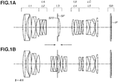
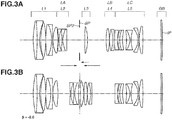
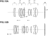
- Figs. 1A , 3A , 5A , 7A , 9A , 11A , 13A , and 15A are cross-sectional diagrams of optical systems according to first to eighth exemplary embodiments, each illustrating an in-focus state on an infinite-distance object.
- Figs. 1B , 3B , 5B , 7B , 9B , 11B , 13B , and 15B are cross-sectional diagrams of the optical systems according to the first to eighth exemplary embodiments, each illustrating aa in-focus state on a finite-distance object. An imaging magnification set in this state is illustrated in each diagram.
- the optical system according to each of the exemplary embodiments is an optical system used in an imaging apparatus such as digital video cameras, digital still cameras, broadcasting cameras, silver-halide film cameras, or monitoring cameras.
- the optical system according to each of the exemplary embodiments includes a plurality of lens units.
- a lens unit refers to a group of lenses integrally moving or stopping in focusing.
- an interval between adjacent lens units changes in focusing from an infinite-distance object to a close-distance object.
- a lens unit may only include a single lens or may include a plurality of lenses.
- a lens unit may include an aperture stop.
- Li denotes an i-th lens unit disposed at an i-th ("i" is a natural number) position when being counted from the object side.
- SP denotes a main stop (aperture stop) for determining (limiting) an F-number (Fno) light beam
- SP2 denotes a sub stop for reducing a stop diameter in accordance with a change in imaging magnification and cutting unnecessary light rays.
- IP denotes an image plane.
- an imaging plane of a solid-state image sensor such as a charge-coupled device (CCD) sensor or a complementary metal-oxide semiconductor (CMOS) sensor is disposed at the image plane IP.
- CMOS complementary metal-oxide semiconductor
- a photosensitive surface corresponding to a film surface is placed at the image plane IP.
- GB denotes an optical filter placed on the object side of the image plane IP.
- the optical system according to each of the exemplary embodiments includes a plurality of focus lens units.
- a focus lens unit refers to a lens unit moving in focusing. Arrows illustrated in each of the lens cross-sectional diagrams indicate moving directions of the focus lens units in focusing from an infinite-distance object to a close-distance object.
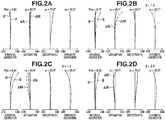
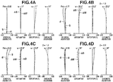
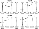
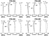
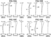
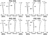
- Figs. 2A, 2B, 2C, 2D , 4A, 4B, 4C, 4D , 6A, 6B, 6C, 6D , 8A, 8B, 8C, 8D , 10A, 10B, 10C, 10D , 12A, 12B, 12C, 12D , 14A, 14B, 14C, 14D , 16A, 16B, 16C, and 16D are aberration diagrams of the optical systems according to the first to eighth exemplary embodiments. In the aberration diagrams, aberration diagrams illustrated in Figs.
- 2A , 4A , 6A , 8A , 10A , 12A , 14A , and 16A are aberration diagrams illustrating an in-focus state on an infinite-distance object
- aberration diagrams illustrated in Figs. 2B to 2D , 4B to 4D , 6B to 6D , 8B to 8D , 10B to 10D , 12B to 12D , 14B to 14D , and 16B to 16D are aberration diagrams illustrating an in-focus state on a finite-distance object.
- 2B to 2D , 4B to 4D , 6B to 6D , 8B to 8D , 10B to 10D , 12B to 12D , 14B to 14D , and 16B to 16D are as illustrated in the corresponding aberration diagrams.
- Fno denotes an F-number
- spherical aberration amounts with respect to d-line (wavelength of 587.6 nm) and g-line (wavelength of 435.8 nm) are illustrated.
- ⁇ S denotes an astigmatism amount on a sagittal image plane
- ⁇ M denotes an astigmatism amount on a meridional image plane.
- ⁇ denotes an imaging half field angle (°).
- a so-called floating system is employed by providing a plurality of focus lens units.
- a lens unit disposed on the object side will be referred to as a first focus lens unit LA
- a lens unit disposed on the image side will be referred to as a second focus lens unit LB.
- the first and second focus lens units LA and LB can be said to be lens units having a main focusing function in the optical system according to each of the exemplary embodiments.
- refractive power of a partial optical system LC including all the lenses disposed on the image side of the second focus lens unit LB is appropriately set.
- the optical system according to each of the exemplary embodiments can thereby have high optical performance while being compact, and can further perform image capturing at high imaging magnification i.e., a same magnification or more.
- the partial optical system LC has negative refractive power.
- this configuration because it is possible to dispose an exit pupil at a position close to the image plane, it is possible to shorten a back focus. This enables the total lens length to be shortened.
- negative refractive power as refractive power of the partial optical system LC, it is possible to reduce a lens diameter of a lens disposed at a position close to the image plane in the optical system.
- the optical system according to each of the exemplary embodiments satisfies the following Conditional Expression (1): ⁇ 3.00 ⁇ fLCX / fX ⁇ ⁇ 0.50 where fLCX is a focal length of the partial optical system LC in the first in-focus state, and fX is a focal length of the entire optical system in the first in-focus state.
- Conditional Expression (1) defines a relationship between a focal length of the entire system and a focal length of the partial optical system LC in the first in-focus state.
- fLCX/fX exceeds an upper limit of Conditional Expression (1), a back focus becomes too short.
- the optical system according to each of the exemplary embodiments can perform image capturing at an imaging magnification of a same magnification or more, and can be compact while having high optical performance.
- the optical system according to each of the exemplary embodiments desirably satisfies one or more conditional expressions of the following Conditional Expressions (2) to (11).
- f is a focal length of the entire optical system in a state in which focus is put on an infinite-distance object.
- fLA is a focal length of the first focus lens unit LA.
- sk is a distance from an image-side lens surface of a lens disposed closest to the image side in the optical system, to the image plane that is set in a state in which focus is put on an infinite-distance object (a back focus in air conversion).
- ESA is a focus sensitivity of the first focus lens unit LA in a state in which focus is put on an infinite-distance object.
- ESB is a focus sensitivity of the second focus lens unit LB in a state in which focus is put on an infinite-distance object.
- MB is an amount of movement of the second focus lens unit LB moved from a state in which focus is put on an infinite-distance object, until the second in-focus state is caused.
- Di is a distance from the aperture stop SP to the image plane IP in a state in which focus is put on an infinite-distance object.
- fL1 is a focal length of a first lens unit L1 in a state in which focus is put on an infinite-distance object.
- fI is a focal length of a lens disposed closest to the image side in the optical system.
- a lens disposed closest to the image side is a single lens element in the optical system according to each of the exemplary embodiments, but a lens disposed closest to the image side may be a cemented lens.
- fI is a focal length in air of a lens disposed closest to the image side among the cemented lens disposed closest to the image side (a focal length obtainable when the cemented lens is separated and each of the separated lenses is regarded as a single lens element).
- ⁇ m is a lateral magnification obtainable when an imaging magnification is largest in the optical system according to each of the exemplary embodiments.
- Conditional Expression (2) defines a relationship between the focal length fLCY of the partial optical system LC and a focal length of the entire system in the second in-focus state.
- Conditional Expression (3) defines a relationship between a focal length of the first focus lens unit LA and a focal length of the entire system.
- Conditional Expression (4) defines a relationship between a back focus of the optical system and a focal length of the partial optical system LC in the second in-focus state. By satisfying Conditional Expression (4), it is possible to further reduce a lens diameter of the partial optical system LC.
- Conditional Expression (5) defines the focus sensitivity ESA of the first focus lens unit LA.
- Conditional Expression (6) defines the focus sensitivity ESB of the second focus lens unit LB.
- Conditional Expression (7) defines a relationship between moving distances of the first focus lens unit LA and the second focus lens unit LB, and the focal length of the entire system. By satisfying Conditional Expression (7), it is possible to further shorten the total lens length.
- Conditional Expression (8) defines a relationship between a distance from the aperture stop SP to the image plane, and the focal length of the entire system.
- Conditional Expression (9) defines a relationship between a focal length of the lens unit L1 and a focal length of the entire system in an in-focus state on an infinite-distance object.
- Conditional Expression (10) defines a relationship between a focal length of the entire system and a focal length of a lens disposed at a position closest to the image plane, in an in-focus state on an infinite-distance object. By satisfying Conditional Expression (10), it is possible to reduce a lens diameter of the partial optical system LC.
- Conditional Expression (11) defines a maximum imaging magnification in each of the exemplary embodiments.
- Conditional Expressions (2) to (11) it is more desirable to set numerical value ranges of Conditional Expressions (2) to (11) to ranges of the following Conditional Expressions (2a) to (11a).
- Conditional Expressions (2) to (11) it is further desirable to set numerical value ranges of Conditional Expressions (2) to (11) to ranges of the following Conditional Expressions (2b) to (11b).
- a lens disposed at a position closest to the image plane IP desirably has positive refractive power.
- a lens disposed at a position closest to the image plane IP is a cemented lens
- a lens disposed closest to the image side among the cemented lens desirably has positive refractive power in air.
- a change in height of an off-axis light ray caused by focusing from an infinite-distance object to a close-distance object is likely to be larger than that of a normal lens.
- the number of focus lens units moving in focusing is to be three or less in each of the exemplary embodiments. In other words, it is desirable that the number of focus lens units is two or three.
- the first lens unit L1 desirably has positive refractive power.
- the first focus lens unit LA desirably has negative refractive power. With this configuration, it becomes possible to appropriately correct various types of aberration generated in the first lens unit L1.
- the first focus lens unit LA and the second focus lens unit LB are disposed on opposite sides with respect to the aperture stop SP. More specifically, it is desirable that the first focus lens unit LA is disposed on a light incident side of the aperture stop SP, and the second focus lens unit LB is disposed on a light emission side of the aperture stop SP. On the light incident side of the aperture stop SP, the height of an on-axis light ray is relatively high, and on the light emission side of the aperture stop SP, the height of an off-axis light ray is relatively high. For this reason, by disposing the first focus lens unit LA and the second focus lens unit LB on opposite sides with respect to the aperture stop SP, it becomes possible to effectively reduce an amount of change in optical performance caused by focusing, over a wide range of a screen.
- the first focus lens unit LA desirably includes three or more lenses including a negative lens and a positive lens.
- the second focus lens unit LB desirably includes two or more lenses including a negative lens and a positive lens. This is because, by a focus lens unit including a negative lens and a positive lens, it is possible to suppress the generation of on-axis chromatic aberration and/or magnification chromatic aberration in focusing.
- the first lens unit L1 is desirably immovable in focusing. With this configuration, it is possible to reduce a shift in gravity center of the optical system in focusing, and enhance operability in focusing.
- the optical system according to the first exemplary embodiment includes, in order from the object side to the image side, the first lens unit L1 having positive refractive power, a second lens unit L2 having negative refractive power, a third lens unit L3 including the aperture stop SP and having positive refractive power, a fourth lens unit L4 having positive refractive power, and a fifth lens unit L5 having negative refractive power.
- the second lens unit L2 corresponds to the first focus lens unit LA, and moves toward the image side in focusing from an infinite-distance object to a close-distance object.
- the fourth lens unit L4 corresponds to the second focus lens unit LB, and moves toward the object side in focusing from an infinite-distance object to a close-distance object.
- the fifth lens unit L5 corresponds to the partial optical system LC.
- the lateral magnification ⁇ m of the optical system according to the first exemplary embodiment is - 2.0.
- the optical system according to the second exemplary embodiment includes, in order from the object side to the image side, the first lens unit L1 having positive refractive power, the second lens unit L2 having negative refractive power, the aperture stop SP, the third lens unit L3 having positive refractive power, the fourth lens unit L4 having positive refractive power, and the fifth lens unit L5 having negative refractive power.
- the second lens unit L2 corresponds to the first focus lens unit LA, and moves toward the image side in focusing from an infinite-distance object to a close-distance object.
- the fourth lens unit L4 corresponds to the second focus lens unit LB, and moves toward the object side in focusing from an infinite-distance object to a close-distance object.
- the fifth lens unit L5 corresponds to the partial optical system LC.
- the third lens unit L3 moves toward the object side in focusing from an infinite-distance object to a close-distance object.
- the lateral magnification ⁇ m of the optical system according to the second exemplary embodiment is -2.0.
- the optical system according to the third exemplary embodiment includes, in order from the object side to the image side, the first lens unit L1 having positive refractive power, the second lens unit L2 having negative refractive power, the aperture stop SP, the third lens unit L3 having positive refractive power, the fourth lens unit L4 having negative refractive power, and the fifth lens unit L5 having positive refractive power.
- the second lens unit L2 corresponds to the first focus lens unit LA, and moves toward the image side in focusing from an infinite-distance object to a close-distance object.
- the third lens unit L3 corresponds to the second focus lens unit LB, and moves toward the object side in focusing from an infinite-distance object to a close-distance object.
- a partial optical system including the fourth lens unit L4 and the fifth lens unit L5 has negative refractive power, and corresponds to the partial optical system LC.
- the fourth lens unit L4 moves toward the object side in focusing from an infinite-distance object to a close-distance object.
- the lateral magnification ⁇ m of the optical system according to the third exemplary embodiment is -1.5.
- the optical system according to the fourth exemplary embodiment includes, in order from the object side to the image side, the first lens unit L1 having positive refractive power, the second lens unit L2 having negative refractive power, the third lens unit L3 including the aperture stop SP and having positive refractive power, the fourth lens unit L4 having positive refractive power, the fifth lens unit L5 having negative refractive power, a sixth lens unit L6 having negative refractive power, a seventh lens unit L7 having negative refractive power, and an eighth lens unit L8 having negative refractive power.
- the second lens unit L2 corresponds to the first focus lens unit LA, and moves toward the image side in focusing from an infinite-distance object to a close-distance object.
- the fourth lens unit L4 corresponds to the second focus lens unit LB, and moves toward the object side in focusing from an infinite-distance object to a close-distance object.
- the fifth to eighth lens units L5 to L8 have negative refractive power as a whole, and correspond to the partial optical system LC.
- the fifth lens unit L5 moves toward the object side in focusing from an infinite-distance object to a close-distance object
- the seventh lens unit L7 moves toward the image side in focusing from an infinite-distance object to a close-distance object.
- the lateral magnification ⁇ m of the optical system according to the fourth exemplary embodiment is -2.8.
- the optical system according to the fifth exemplary embodiment includes, in order from the object side to the image side, the first lens unit L1 having positive refractive power, the second lens unit L2 having negative refractive power, the third lens unit L3 including the aperture stop SP and having positive refractive power, the fourth lens unit L4 having negative refractive power, and the fifth lens unit L5 having negative refractive power.
- the second lens unit L2 corresponds to the first focus lens unit LA, and moves toward the image side in focusing from an infinite-distance object to a close-distance object.
- the fourth lens unit L4 corresponds to the second focus lens unit LB, and moves toward the image side in focusing from an infinite-distance object to a close-distance object.
- the fifth lens unit L5 corresponds to the partial optical system LC.
- the lateral magnification ⁇ m of the optical system according to the fifth exemplary embodiment is -1.5.
- the optical system according to the sixth exemplary embodiment includes, in order from the object side to the image side, the first lens unit L1 having positive refractive power, the second lens unit L2 having negative refractive power, the third lens unit L3 including the aperture stop SP and having positive refractive power, the fourth lens unit L4 having negative refractive power, and the fifth lens unit L5 having negative refractive power.
- the second lens unit L2 corresponds to the first focus lens unit LA, and moves toward the image side in focusing from an infinite-distance object to a close-distance object.
- the fourth lens unit L4 corresponds to the second focus lens unit LB, and moves toward the image side in focusing from an infinite-distance object to a close-distance object.
- the fifth lens unit L5 corresponds to the partial optical system LC.
- the fifth lens unit L5 moves toward the image side in focusing from an infinite-distance object to a close-distance object.
- the lateral magnification ⁇ m of the optical system according to the sixth exemplary embodiment is -2.0.
- the optical system according to the seventh exemplary embodiment includes, in order from the object side to the image side, the first lens unit L1 having negative refractive power, the second lens unit L2 having positive refractive power, the third lens unit L3 including the aperture stop SP and having negative refractive power, the fourth lens unit L4 having positive refractive power, and the fifth lens unit L5 having negative refractive power.
- the second lens unit L2 corresponds to the first focus lens unit LA, and moves toward the object side in focusing from an infinite-distance object to a close-distance object.
- the fourth lens unit L4 corresponds to the second focus lens unit LB, and moves toward the object side in focusing from an infinite-distance object to a close-distance object.
- the fifth lens unit L5 corresponds to the partial optical system LC.
- the lateral magnification ⁇ m of the optical system according to the seventh exemplary embodiment is -1.3.
- the optical system according to the eighth exemplary embodiment includes, in order from the object side to the image side, the first lens unit L1 having positive refractive power, the second lens unit L2 having positive refractive power, the third lens unit L3 including the aperture stop SP and having negative refractive power, the fourth lens unit L4 having negative refractive power, and the fifth lens unit L5 having negative refractive power.
- the second lens unit L2 corresponds to the first focus lens unit LA, and moves toward the object side in focusing from an infinite-distance object to a close-distance object.
- the fourth lens unit L4 corresponds to the second focus lens unit LB, and moves toward the image side in focusing from an infinite-distance object to a close-distance object.
- the fifth lens unit L5 corresponds to the partial optical system LC.
- the lateral magnification ⁇ m of the optical system according to the eighth exemplary embodiment is -1.5.
- r denotes a curvature radius of each optical surface
- d denotes an on-axis interval (distance on an optical axis) between an m-th surface and an (m+1)-th surface.
- m denotes an ordinal number of a surface counted from the light incident side.
- nd denotes refractive index with respect to d-line of each optical component
- vd denotes Abbe number of each optical component.
- all values of "d”, focal length (mm), F-number, and half field angle (°) are values obtained when the optical system according to each of the exemplary embodiments is in-focus state on an infinite-distance object.
- a back focus BF is a distance from a final lens surface to the image plane.
- the total lens length is a value obtained by adding a back focus to a distance from a first lens surface to a final lens surface.
- an aspherical-shaped lens surface is indicated by asterisk (*) added after a surface number.
- "e ⁇ P" in aspherical surface data means “ ⁇ 10 ⁇ P ".
- Conditional Expression (1) fLCX/fX - 0.70 - 0.78 0.68 - 0.70 - 1.01 - 1.24 - 1.47 - 2.19 Conditional Expression (2) fLCY/f - 0.32 - 0.31 - 0.37 - 0.32 - 0.53 - 0.61 - 1.00 - 0.84 Conditional Expression (3)
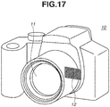
- the digital still camera includes a camera main body 10, and an imaging optical system 11 including any of the optical systems described in the first to eighth exemplary embodiments.
- the digital still camera further includes a solid-state image sensor (photoelectric conversion element) 12 such as a CCD sensor or a CMOS sensor that is built in the camera main body 10, and that receives and photoelectrically converts an optical image formed by the imaging optical system 11.
- the camera main body 10 may be a so-called single-lens reflex camera including a quick return mirror, or may be a so-called mirrorless camera not including an instant return mirror.
- the optical system according to an exemplary embodiment of the present invention for an imaging apparatus such as a digital still camera, it is possible to perform image capturing at an imaging magnification of a same magnification or more, and it is possible to obtain a compact imaging apparatus having high optical performance.
Landscapes
- Physics & Mathematics (AREA)
- General Physics & Mathematics (AREA)
- Optics & Photonics (AREA)
- Lenses (AREA)
- Nonlinear Science (AREA)
Applications Claiming Priority (1)
| Application Number | Priority Date | Filing Date | Title |
|---|---|---|---|
| JP2018194671A JP7114436B2 (ja) | 2018-10-15 | 2018-10-15 | 光学系およびそれを有する撮像装置 |
Publications (1)
| Publication Number | Publication Date |
|---|---|
| EP3640697A1 true EP3640697A1 (en) | 2020-04-22 |
Family
ID=68136315
Family Applications (1)
| Application Number | Title | Priority Date | Filing Date |
|---|---|---|---|
| EP19201195.5A Pending EP3640697A1 (en) | 2018-10-15 | 2019-10-02 | Optical system and imaging apparatus including the same |
Country Status (4)
| Country | Link |
|---|---|
| US (2) | US11467385B2 (zh) |
| EP (1) | EP3640697A1 (zh) |
| JP (1) | JP7114436B2 (zh) |
| CN (1) | CN111045181B (zh) |
Families Citing this family (1)
| Publication number | Priority date | Publication date | Assignee | Title |
|---|---|---|---|---|
| WO2021006002A1 (ja) * | 2019-07-09 | 2021-01-14 | 株式会社ニコン | 光学系、光学装置および光学系の製造方法 |
Citations (5)
| Publication number | Priority date | Publication date | Assignee | Title |
|---|---|---|---|---|
| US20040017605A1 (en) * | 2002-04-22 | 2004-01-29 | Olympus Optical Co., Ltd. | Telephoto lens and telephoto lens apparatus having the same |
| US20140334014A1 (en) * | 2013-05-09 | 2014-11-13 | Sony Corporation | Macro lens and imaging unit |
| JP2015034899A (ja) | 2013-08-09 | 2015-02-19 | 株式会社タムロン | 光学系及び光学系のフォーカシング方法 |
| JP2015215494A (ja) * | 2014-05-12 | 2015-12-03 | キヤノン株式会社 | 光学系及びそれを有する撮像装置 |
| US20180246292A1 (en) * | 2017-02-28 | 2018-08-30 | Fujifilm Corporation | Imaging lens and imaging apparatus |
Family Cites Families (8)
| Publication number | Priority date | Publication date | Assignee | Title |
|---|---|---|---|---|
| JP4450894B2 (ja) * | 1999-07-16 | 2010-04-14 | 株式会社シグマ | マクロレンズ |
| JP5584064B2 (ja) * | 2010-09-13 | 2014-09-03 | 株式会社シグマ | マクロレンズ |
| KR101853810B1 (ko) | 2010-10-01 | 2018-05-03 | 삼성전자주식회사 | 접사 렌즈계 및 이를 구비한 촬영 장치 |
| JP5790106B2 (ja) | 2011-04-12 | 2015-10-07 | 株式会社ニコン | 光学系、光学装置、光学系の製造方法 |
| JP2013152279A (ja) * | 2012-01-24 | 2013-08-08 | Olympus Imaging Corp | 撮影レンズ系及びそれを備えた撮像装置 |
| JP6230933B2 (ja) | 2014-02-28 | 2017-11-15 | 富士フイルム株式会社 | マクロレンズおよび撮像装置 |
| CN104199179B (zh) | 2014-08-11 | 2017-09-22 | 安徽长庚光学科技有限公司 | 一种微距镜头 |
| EP3026481A1 (en) | 2014-11-28 | 2016-06-01 | Canon Kabushiki Kaisha | Zoom lens and image pickup apparatus including the same |
-
2018
- 2018-10-15 JP JP2018194671A patent/JP7114436B2/ja active Active
-
2019
- 2019-10-02 EP EP19201195.5A patent/EP3640697A1/en active Pending
- 2019-10-03 US US16/592,391 patent/US11467385B2/en active Active
- 2019-10-15 CN CN201910976752.4A patent/CN111045181B/zh active Active
-
2022
- 2022-08-18 US US17/820,846 patent/US20220404596A1/en active Pending
Patent Citations (5)
| Publication number | Priority date | Publication date | Assignee | Title |
|---|---|---|---|---|
| US20040017605A1 (en) * | 2002-04-22 | 2004-01-29 | Olympus Optical Co., Ltd. | Telephoto lens and telephoto lens apparatus having the same |
| US20140334014A1 (en) * | 2013-05-09 | 2014-11-13 | Sony Corporation | Macro lens and imaging unit |
| JP2015034899A (ja) | 2013-08-09 | 2015-02-19 | 株式会社タムロン | 光学系及び光学系のフォーカシング方法 |
| JP2015215494A (ja) * | 2014-05-12 | 2015-12-03 | キヤノン株式会社 | 光学系及びそれを有する撮像装置 |
| US20180246292A1 (en) * | 2017-02-28 | 2018-08-30 | Fujifilm Corporation | Imaging lens and imaging apparatus |
Also Published As
| Publication number | Publication date |
|---|---|
| CN111045181B (zh) | 2022-04-19 |
| US11467385B2 (en) | 2022-10-11 |
| US20200116985A1 (en) | 2020-04-16 |
| US20220404596A1 (en) | 2022-12-22 |
| JP2020064123A (ja) | 2020-04-23 |
| JP7114436B2 (ja) | 2022-08-08 |
| CN111045181A (zh) | 2020-04-21 |
Similar Documents
| Publication | Publication Date | Title |
|---|---|---|
| US9509912B2 (en) | Zoom lens and image pickup apparatus including the same | |
| EP2927726B1 (en) | Zoom lens and image pickup apparatus including the same | |
| EP2942655B1 (en) | Optical system and image pickup apparatus including the same | |
| US10983315B2 (en) | Optical system and imaging apparatus | |
| US7688520B2 (en) | Zoom lens system and camera including the same | |
| CN106597646B (zh) | 光学系统和包括该光学系统的摄像装置 | |
| US8873169B2 (en) | Zoom lens and image pickup apparatus using the same | |
| US11668899B2 (en) | Zoom lens, optical apparatus, and method for manufacturing zoom lens | |
| CN110244439B (zh) | 变焦透镜和图像拾取装置 | |
| US8873155B2 (en) | Zoom lens and image pickup apparatus having the same | |
| CN111812800B (zh) | 光学系统和具有光学系统的成像装置 | |
| CN109946824B (zh) | 变焦透镜及摄像装置 | |
| JP2018072367A (ja) | ズームレンズ及びそれを有する撮像装置 | |
| US20220404596A1 (en) | Optical system and imaging apparatus including the same | |
| US20220334363A1 (en) | Optical system and image pickup apparatus having the same | |
| EP3767362B1 (en) | Optical system and optical apparatus | |
| EP3798709B1 (en) | Zoom lens and imaging apparatus including the same | |
| US11256062B2 (en) | Optical system and image pickup apparatus | |
| CN111983792B (zh) | 变焦透镜和包括该变焦透镜的成像装置 | |
| EP3828613B1 (en) | Zoom lens and image capturing apparatus including the same | |
| US11782252B2 (en) | Optical system and image capturing apparatus including the same | |
| US20230305277A1 (en) | Zoom lens and image capturing apparatus including the same | |
| CN114815191A (zh) | 变焦镜头和具有变焦镜头的摄像设备 |
Legal Events
| Date | Code | Title | Description |
|---|---|---|---|
| PUAI | Public reference made under article 153(3) epc to a published international application that has entered the european phase |
Free format text: ORIGINAL CODE: 0009012 |
|
| STAA | Information on the status of an ep patent application or granted ep patent |
Free format text: STATUS: THE APPLICATION HAS BEEN PUBLISHED |
|
| AK | Designated contracting states |
Kind code of ref document: A1 Designated state(s): AL AT BE BG CH CY CZ DE DK EE ES FI FR GB GR HR HU IE IS IT LI LT LU LV MC MK MT NL NO PL PT RO RS SE SI SK SM TR |
|
| AX | Request for extension of the european patent |
Extension state: BA ME |
|
| STAA | Information on the status of an ep patent application or granted ep patent |
Free format text: STATUS: REQUEST FOR EXAMINATION WAS MADE |
|
| 17P | Request for examination filed |
Effective date: 20201022 |
|
| RBV | Designated contracting states (corrected) |
Designated state(s): AL AT BE BG CH CY CZ DE DK EE ES FI FR GB GR HR HU IE IS IT LI LT LU LV MC MK MT NL NO PL PT RO RS SE SI SK SM TR |
|
| STAA | Information on the status of an ep patent application or granted ep patent |
Free format text: STATUS: EXAMINATION IS IN PROGRESS |
|
| 17Q | First examination report despatched |
Effective date: 20220801 |