EP2942655B1 - Optical system and image pickup apparatus including the same - Google Patents
Optical system and image pickup apparatus including the same Download PDFInfo
- Publication number
- EP2942655B1 EP2942655B1 EP15001294.6A EP15001294A EP2942655B1 EP 2942655 B1 EP2942655 B1 EP 2942655B1 EP 15001294 A EP15001294 A EP 15001294A EP 2942655 B1 EP2942655 B1 EP 2942655B1
- Authority
- EP
- European Patent Office
- Prior art keywords
- lens unit
- optical system
- focus
- refractive power
- negative refractive
- Prior art date
- Legal status (The legal status is an assumption and is not a legal conclusion. Google has not performed a legal analysis and makes no representation as to the accuracy of the status listed.)
- Active
Links
Images


Classifications
-
- G—PHYSICS
- G02—OPTICS
- G02B—OPTICAL ELEMENTS, SYSTEMS OR APPARATUS
- G02B13/00—Optical objectives specially designed for the purposes specified below
- G02B13/001—Miniaturised objectives for electronic devices, e.g. portable telephones, webcams, PDAs, small digital cameras
- G02B13/0015—Miniaturised objectives for electronic devices, e.g. portable telephones, webcams, PDAs, small digital cameras characterised by the lens design
- G02B13/002—Miniaturised objectives for electronic devices, e.g. portable telephones, webcams, PDAs, small digital cameras characterised by the lens design having at least one aspherical surface
- G02B13/0045—Miniaturised objectives for electronic devices, e.g. portable telephones, webcams, PDAs, small digital cameras characterised by the lens design having at least one aspherical surface having five or more lenses
-
- G—PHYSICS
- G02—OPTICS
- G02B—OPTICAL ELEMENTS, SYSTEMS OR APPARATUS
- G02B13/00—Optical objectives specially designed for the purposes specified below
- G02B13/24—Optical objectives specially designed for the purposes specified below for reproducing or copying at short object distances
- G02B13/26—Optical objectives specially designed for the purposes specified below for reproducing or copying at short object distances for reproducing with unit magnification
-
- G—PHYSICS
- G02—OPTICS
- G02B—OPTICAL ELEMENTS, SYSTEMS OR APPARATUS
- G02B15/00—Optical objectives with means for varying the magnification
- G02B15/14—Optical objectives with means for varying the magnification by axial movement of one or more lenses or groups of lenses relative to the image plane for continuously varying the equivalent focal length of the objective
- G02B15/145—Optical objectives with means for varying the magnification by axial movement of one or more lenses or groups of lenses relative to the image plane for continuously varying the equivalent focal length of the objective having five groups only
- G02B15/1451—Optical objectives with means for varying the magnification by axial movement of one or more lenses or groups of lenses relative to the image plane for continuously varying the equivalent focal length of the objective having five groups only the first group being positive
- G02B15/145121—Optical objectives with means for varying the magnification by axial movement of one or more lenses or groups of lenses relative to the image plane for continuously varying the equivalent focal length of the objective having five groups only the first group being positive arranged +-+-+
-
- G—PHYSICS
- G02—OPTICS
- G02B—OPTICAL ELEMENTS, SYSTEMS OR APPARATUS
- G02B15/00—Optical objectives with means for varying the magnification
- G02B15/14—Optical objectives with means for varying the magnification by axial movement of one or more lenses or groups of lenses relative to the image plane for continuously varying the equivalent focal length of the objective
- G02B15/16—Optical objectives with means for varying the magnification by axial movement of one or more lenses or groups of lenses relative to the image plane for continuously varying the equivalent focal length of the objective with interdependent non-linearly related movements between one lens or lens group, and another lens or lens group
- G02B15/20—Optical objectives with means for varying the magnification by axial movement of one or more lenses or groups of lenses relative to the image plane for continuously varying the equivalent focal length of the objective with interdependent non-linearly related movements between one lens or lens group, and another lens or lens group having an additional movable lens or lens group for varying the objective focal length
-
- H—ELECTRICITY
- H04—ELECTRIC COMMUNICATION TECHNIQUE
- H04N—PICTORIAL COMMUNICATION, e.g. TELEVISION
- H04N23/00—Cameras or camera modules comprising electronic image sensors; Control thereof
- H04N23/50—Constructional details
- H04N23/54—Mounting of pick-up tubes, electronic image sensors, deviation or focusing coils
Definitions
- the present invention relates to an optical system and an image pickup apparatus including the same, which are suitable for, for example, an image pickup optical system used in an image pickup apparatus such as a digital still camera, a digital video camera, a television (TV) camera, a monitoring camera, a silver-halide film camera, or the like.
- an image pickup optical system used in an image pickup apparatus such as a digital still camera, a digital video camera, a television (TV) camera, a monitoring camera, a silver-halide film camera, or the like.
- an image pickup optical system used in an image pickup apparatus retain, during focusing, reduced aberration variation and enhanced optical performance at any object distance, and have compact and light-weight focus lens units, which facilitate high-speed focusing.
- Focus types typically employed for the image pickup optical system include an inner focus type where part of the lens units in the image pickup optical system works for focusing.
- the inner focus type more easily enables downsizing and reduction in weight of the lens units for focusing (focus lens units) and facilitates high-speed focusing, compared with some other focus types where all the components of the image pickup optical system are required to be moved.
- a shorter photographing distance develops various aberrations more.
- various aberrations are significantly increased, resulting in deteriorated optical performance.
- a photographing lens primarily used for photographing the object at short distance is known as "macro lens”.
- Japanese Patent Application Laid-Open No. 2006-153942 and Japanese Patent Application Laid-Open No. 2011-048232 there is disclosed an image pickup optical system of a floating type where two or more of the lens units are configured to move during the focusing to reduce the variations in aberrations due to the focusing.
- an image pickup optical system consisting of four lens units, namely, a first positive lens unit, a second negative lens unit, a third positive lens unit, and a fourth negative lens unit arranged in the stated order from the object side to the image side.
- the second lens unit is moved toward the image side while the third lens unit is moved toward the object side.
- an image pickup optical system consisting of six lens units, namely, a first positive lens unit, a second negative lens unit, a third positive lens unit, a fourth positive lens unit, a fifth negative lens unit, and a sixth positive lens unit arranged in the stated order from the object side to the image side. For focusing from an object at infinity to an object at short distance, at least three lens units are moved.
- US 2004/0017605 A1 discloses a telephoto lens comprising, in order from an object side, a first positive lens unit, a second negative lens unit, a third positive lens unit and a fourth negative lens unit, wherein the first lens unit consists of at least two positive lenses and two negative lenses, and wherein in focusing toward proximity, the second lens unit and the fourth lens unit are moved toward an image side.
- US 2013/0188091 A1 discloses a macro lens comprising a frontmost lens unit arranged closest to the object side, a rearmost lens unit arranged closest to the image side, and a plurality of lens units that are arranged in between, wherein one of the plurality of lens units is a first focusing lens unit, and wherein in a first shooting mode, only the first focusing lens unit moves toward the image side during focusing from infinity to proximity, and in a second shooting mode, at least two lens units in the lens system move during focusing from infinity to proximity
- An optical system according to one embodiment of the present invention is defined in claim 1. Further provided is an image pickup apparatus as defined in claim 11. The other claims relate to further developments.
- an optical system and an image pickup apparatus including the same are described.
- an optical system including a plurality of lens units, in which an interval between adjacent lens units changes during focusing.
- the lens unit having a positive refractive power is arranged closest to an object side.
- the optical system includes focus lens units LF1 and LF2 each having a negative refractive power, which are moved during the focusing, and an intermediate lens unit having a positive refractive power, which is arranged between the two focus lens units.
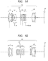
- FIGS. 1A and 1B are lens cross-sectional views of the optical system according to Embodiment 1 of the present invention when focus is at an object of infinity and short distance, respectively.
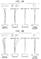
- FIGS. 2A and 2B are longitudinal aberration diagrams of the optical system according to Embodiment 1 when focus is at the object of infinity and short distance, respectively.
- Embodiment 1 is an optical system having an angle of field of 28.52 degrees and an F-number of about 3.5.
- FIGS. 3A and 3B are lens cross-sectional views of the optical system according to Embodiment 2 of the present invention when focus is at the object of infinity and short distance, respectively.
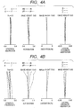
- FIGS. 4A and 4B are longitudinal aberration diagrams of the optical system according to Embodiment 2 when focus is at the object of infinity and short distance, respectively.
- Embodiment 2 is an optical system having an angle of field of 32.82 degrees and an F-number of about 3.5.
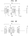
- FIGS. 5A and 5B are lens cross-sectional views of the optical system according to Embodiment 3 of the present invention when focus is at the object of infinity and short distance, respectively.
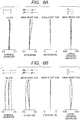
- FIGS. 6A and 6B are longitudinal aberration diagrams of the optical system according to Embodiment 3 when focus is at the object of infinity and short distance, respectively.
- Embodiment 3 is an optical system having an angle of field of 26.44 degrees and an F-number of about 2.92.
- FIG. 7 is a schematic view illustrating a main part of an image pickup apparatus according to the present invention.
- the left is an object side (front side, magnifying side), whereas the right is an image side (rear side, reducing side).
- the optical system is represented by OL.
- a first lens unit L1 has a positive refractive power
- a second lens unit L2 has a negative refractive power
- a third lens unit has a positive refractive power
- a fourth lens unit has a negative refractive power
- a fifth lens unit has a positive refractive power.
- the lens units according to the present invention are separated from each other depending on the change in intervals between the lens units during the focusing. Any of the lens units may have at least a single lens instead of necessarily consisting of at least one lens.
- the optical system includes an aperture stop SP and an auxiliary stop SSP with a fixed aperture ratio (flare-cut stop). Movement loci followed by the lens units during the focusing from an object at infinity to an object at short distance are expressed by the arrows with the description "focus”.
- An image plane IP corresponds to an image pickup plane of a solid-state image pickup element (photoelectric conversion element) such as a CCD sensor or a CMOS sensor when used as an imaging optical system of a video camera or a digital still camera, and corresponds to a film plane when used for a silver-halide film camera.
- symbols d, g, C, and F represent the d-line, the g-line, the C-line, and the F-line, respectively.
- symbol dM represents a meridional image plane on the d-line
- symbol dS represents a sagittal image plane on the d-line
- symbol gM represents a meridional image plane on the g-line
- symbol gS represents a sagittal image plane on the g-line.
- symbols g, C, and F represent the g-line, the C-line, and the F-line, respectively.
- Symbol Fno represents an F-number.
- at least two of the lens units having negative refractive powers are configured to move for focusing.
- the intermediate lens unit having a positive refractive power is arranged between the focus lens units LF1 and LF2.
- the intermediate lens unit is arranged in the vicinity of the aperture stop SP so as to reduce an effective aperture of the intermediate lens unit.
- incident beams are converged by the intermediate lens unit having a positive refractive power so as to enable a reduction in dimensions of the focus lens unit LF2 that is to be arranged on the image side of the intermediate lens unit.
- the focus lens units can be effectively reduced in dimensions and weight.
- the "movement amount” described herein is a difference in axial distance from a position of each of the focus lens units when the optical system is in focus at infinity to another position of the focus lens unit when the optical system is in focus on an object at short distance.
- positive is used when the position of the focus lens unit that is in focus on an object at short distance is on the image side of the position of the focus lens unit that is in focus on an object at infinity.
- conditional expressions (1) and (2) relate to the movement amounts and focal lengths of the focus lens units LF1 and LF2, respectively.
- absolute values of the refractive powers (i.e., negative refractive powers) of the focus lens units LF1 and LF2 are reduced to such an extent that the ratios mn1/fn1 and mn2/fn2 exceed the upper limits defined in the conditional expressions (1) and (2), the movement amounts of the focus lens units during the focusing are increased, thereby increasing the entire length of the lens.
- the absolute values of the refractive powers (i.e., negative refractive powers) of the focus lens units LF1 and LF2 are increased to such an extent that the ratios mn1/fn1 and mn2/fn2 are smaller than the lower limits defined in the conditional expressions (1) and (2), the variations in various aberrations developed in the optical system are increased to prevent the optical system from retaining satisfactory optical performance.
- conditional expressions (1) and (2) it is preferred to set the numerical range of the conditional expressions (1) and (2) as follows: ⁇ 0.60 ⁇ mn 1 / fn 1 ⁇ ⁇ 0.30 ⁇ 0.60 ⁇ mn 2 / fn 2 ⁇ ⁇ 0.30 It is more preferred that at least one of the conditional expressions is satisfied. It is preferred that at least one of the following conditional expressions is satisfied.
- fp represents a focal length of the intermediate lens unit
- finf represents a focal length of the optical system when being in-focus on an object at infinity
- ⁇ inf1 and ⁇ inf2 represent lateral magnifications of the focus lens units LF1 and LF2 when being in-focus on an object at infinity
- ⁇ mod1 and ⁇ mod2 represent lateral magnifications of the focus lens units LF1 and LF2 when being in-focus on an object at short distance
- f1 represents a focal length of the positive lens unit arranged closest
- the conditional expression (3) relates to the focal length of the intermediate lens unit arranged between the two focus lens units LF1 and LF2.
- the intermediate lens converges the incident beams with the accordingly reduced power, thereby increasing the focus lens units LF1 and LF2 in dimensions.
- the positive power of the intermediate lens unit increases to such an extent that the ratio fp/finf is smaller than the lower limit defined in the conditional expression (3), the variations in aberrations developed during the focusing are increased, and it is difficult to sufficiently compensate for various aberrations.
- the conditional expressions (4) and (5) relate to the focal lengths of the focus lens units LF1 and LF2, respectively.
- the negative powers of the focus lens units LF1 and LF2 increase to such an extent that the upper limit conditions of the conditional expressions (4) and (5) are not satisfied, it is difficult to sufficiently compensate for various aberrations.
- the negative powers of the focus lens units LF1 and LF2 decrease to such an extent that the lower limit conditions of the conditional expressions (4) and (5) are not satisfied, the movement amounts of the focus lens units during the focusing are increased, thereby increasing the entire length of the lens.
- the conditional expressions (6) and (7) relate to the lateral magnifications of the focus lens units LF1 and LF2 each having a negative refractive power.
- variations in lateral magnifications increase to such an extent that the ratios ⁇ inf1/ ⁇ mod1 and ⁇ inf2/ ⁇ mod2 exceed the upper limits defined in the conditional expressions (6) and (7), it is difficult to sufficiently compensate for various aberrations.
- variations in lateral magnifications decrease to such an extent that the ratios ⁇ inf1/ ⁇ mod1 and ⁇ inf2/ ⁇ mod2 are smaller than the lower limits defined in the conditional expressions (6) and (7), the movement amounts of the focus lens units during the focusing are increased, thereby increasing the optical system as a whole in dimensions.
- the conditional expression (8) relates to the focal length of the first lens unit L1 having a positive refractive power and arranged closest to the object side.
- the first lens unit L1 converges the incident beams with the accordingly reduced refractive power, thereby increasing the entire length of the optical system.
- the refractive power of the first lens unit L1 is excessively intense to such an extent that the ratio f1/finf is smaller than the lower limit defined in the conditional expression (8), the various aberrations developed in the optical system are increased to prevent the optical system from obtaining satisfactorily enhanced optical performance.
- Embodiments of the present invention can effectively reduce the variations in various aberrations developed during the focusing from an object at infinity to an object at short distance in which an image-to-object ratio is approximately 1.
- the optical system according to Embodiments consists of, in order from the object side to the image side, a first lens unit L1 having a positive refractive power, a second lens unit L2 having a negative refractive power, a third lens unit L3 having a positive refractive power, a fourth lens unit L4 having a negative refractive power, and a fifth lens unit L5 having a positive refractive power.
- the second and fourth lens units L2 and L4 are the focus lens units, which are configured to move toward the image side for the focusing from an object at infinity to an object at short distance. In such a situation, the second and fourth lens units L2 and L4 are configured to move with different loci during the focusing.
- each of Embodiments employs a focus type where the second and fourth lens units L2 and L4 each having a negative refractive power are moved toward the image side for the focusing from an object at infinity to an object at short distance.
- the configuration of arranging the third positive lens unit (i.e., the intermediate lens unit) L3 in the vicinity of the aperture stop SP reduces the effective aperture of the third positive lens unit L3.
- converging the incident beams by the third positive lens unit L3 facilitates the downsizing of the fourth lens unit L4.
- the second and fourth lens units L2 and L4 are configured to satisfy the conditional expression (1).
- the second and fourth lens units L2 and L4 are moved toward the image side for the focusing from an object at infinity to an object at short distance.
- the first, third, and fifth lens units L1, L3, and L5 are configured so as not to move during the focusing.
- the second and fourth lens units L2 and L4 alone are configured to move toward the image side for the focusing from an object at infinity to an object at short distance.
- the first, third, and fifth lens units L1, L3, and L5 are configured to move along a locus convex toward the image side during the focusing from an object at infinity to an object at short distance. Further, the second and fourth lens units L2 and L4 are configured to move toward the image side for the focusing from the object at infinity to an object at short distance.
- the first and third lens units L1 and L3 are configured so as not to move during the focusing.
- the second and fourth lens units L2 and L4 are configured to move toward the image side and the fifth lens unit L5 is configured to move along a locus convex toward the object side for the focusing from an object at infinity to an object at short distance.
- the camera system includes a single-lens reflex camera body 10, an interchangeable lens 11 having the optical system according to the present invention mounted therein, a memory unit 12, such as a film or an image pickup element for recording an image of (receiving light from) an object formed by the interchangeable lens 11, a viewfinder optical system 13 used to see the image of the object formed by the interchangeable lens 11, and a quick return mirror 14 that pivots so as to selectively guide the beams from the interchangeable lens 11 to the memory unit 12 and the viewfinder optical system 13.
- a single-lens reflex camera body 10 an interchangeable lens 11 having the optical system according to the present invention mounted therein
- a memory unit 12 such as a film or an image pickup element for recording an image of (receiving light from) an object formed by the interchangeable lens 11
- a viewfinder optical system 13 used to see the image of the object formed by the interchangeable lens 11
- a quick return mirror 14 that pivots so as to selectively guide the beams from the interchangeable lens 11 to the memory unit 12 and
- the image of the object is reflected by the quick return mirror 14 and imaged on a focusing glass 15, and is inverted into an erect image by a penta prism 16. Then, the erect image is enlarged by an ocular optical system 17.
- the quick return mirror 14 pivots in a direction indicated by the arrow to form and store the image of the object in the memory unit 12.
- a sub-mirror 18 and a focal point detecting device 19 are also provided.
- the optical system of the present invention to the image pickup apparatus such as the interchangeable lens of the single-lens reflex camera achieves the image pickup apparatus that facilitates the imaging of enhanced optical performance at any object distance.
- the present invention can also be similarly applied to a camera without the quick return mirror.
- Numerical Embodiments 1 to 3 corresponding to Embodiments 1 to 3 of the optical system according to the present invention are shown below.
- symbol i represents a surface number counted from the object side.
- symbol ri represents a radius of curvature of the i-th lens surface in the order from the object side
- symbol di represents a lens thickness or an air interval between the i-th surface and an (i+1)th surface
- symbols ndi and vdi represent a refractive index and an Abbe constant in the d-line of a lens material between the i-th surface and the (i+1)th surface counted from the object side, respectively.
- the description of "variable" replaced with an actual value of the interval between adjacent lens surfaces refers to an amount by which the object distance (magnification of photography) changes.
Description
- The present invention relates to an optical system and an image pickup apparatus including the same, which are suitable for, for example, an image pickup optical system used in an image pickup apparatus such as a digital still camera, a digital video camera, a television (TV) camera, a monitoring camera, a silver-halide film camera, or the like.
- It is desired that an image pickup optical system used in an image pickup apparatus retain, during focusing, reduced aberration variation and enhanced optical performance at any object distance, and have compact and light-weight focus lens units, which facilitate high-speed focusing. Focus types typically employed for the image pickup optical system include an inner focus type where part of the lens units in the image pickup optical system works for focusing. The inner focus type more easily enables downsizing and reduction in weight of the lens units for focusing (focus lens units) and facilitates high-speed focusing, compared with some other focus types where all the components of the image pickup optical system are required to be moved.
- In general, in the image pickup optical system, a shorter photographing distance develops various aberrations more. Especially, when an object being photographed is at so close a range as an image-to-object ratio is approximately 1, various aberrations are significantly increased, resulting in deteriorated optical performance. A photographing lens primarily used for photographing the object at short distance is known as "macro lens". In Japanese Patent Application Laid-Open No.
2006-153942 2011-048232 - In Japanese Patent Application Laid-Open No.
2006-153942 - In Japanese Patent Application Laid-Open No.
2011-048232 -
US 2004/0017605 A1 discloses a telephoto lens comprising, in order from an object side, a first positive lens unit, a second negative lens unit, a third positive lens unit and a fourth negative lens unit, wherein the first lens unit consists of at least two positive lenses and two negative lenses, and wherein in focusing toward proximity, the second lens unit and the fourth lens unit are moved toward an image side.US 2013/0188091 A1 discloses a macro lens comprising a frontmost lens unit arranged closest to the object side, a rearmost lens unit arranged closest to the image side, and a plurality of lens units that are arranged in between, wherein one of the plurality of lens units is a first focusing lens unit, and wherein in a first shooting mode, only the first focusing lens unit moves toward the image side during focusing from infinity to proximity, and in a second shooting mode, at least two lens units in the lens system move during focusing from infinity to proximity - In general, in focusing of the inner focus type and the floating type, it is important to appropriately set the refractive power and the configuration of each of the lens units of the image pickup optical system. Especially, it is important to appropriately select which of the plurality of the lens units are to be moved as floating lens elements.
- Unless those factors are appropriately specified, there arise difficulties in making the focus lens units more compact and lighter in weight, reducing the variations in aberrations during the focusing, and obtaining enhanced optical performance for focusing at any object distance from an object at infinity to an object at short distance.
- An optical system according to one embodiment of the present invention is defined in
claim 1. Further provided is an image pickup apparatus as defined inclaim 11. The other claims relate to further developments. - Further features of the present invention will become apparent from the following description of exemplary embodiments with reference to the attached drawings.
-
-
FIG. 1A is a lens cross-sectional view when focusing on an object at infinity according toEmbodiment 1 of the present invention. -
FIG. 1B is a lens cross-sectional view when focusing on an object at short distance according toEmbodiment 1. -
FIG. 2A is an aberration diagram when focusing on an object at infinity according toEmbodiment 1. -
FIG. 2B is an aberration diagram when focusing on an object at short distance according toEmbodiment 1. -
FIG. 3A is a lens cross-sectional view when focusing on an object at infinity according to Embodiment 2 of the present invention. -
FIG. 3B is a lens cross-sectional view when focusing on an object at short distance according to Embodiment 2. -
FIG. 4A is an aberration diagram when focusing on an object at infinity according to Embodiment 2. -
FIG. 4B is an aberration diagram when focusing on an object at short distance according to Embodiment 2. -
FIG. 5A is a lens cross-sectional view when focusing on an object at infinity according to Embodiment 3 of the present invention. -
FIG. 5B is a lens cross-sectional view when focusing on an object at short distance according to Embodiment 3. -
FIG. 6A is an aberration diagram when focusing on an object at infinity according to Embodiment 3. -
FIG. 6B is an aberration diagram when focusing on an object at short distance according to Embodiment 3. -
FIG. 7 is a schematic view illustrating a main part of an image pickup apparatus according to the present invention. - Preferred embodiments of the present invention will now be described in detail in accordance with the accompanying drawings.
- Now, an optical system and an image pickup apparatus including the same according to the present invention are described. According to the present invention, there is provided an optical system including a plurality of lens units, in which an interval between adjacent lens units changes during focusing. Among all of the plurality of lens units, the lens unit having a positive refractive power is arranged closest to an object side. Further, the optical system includes focus lens units LF1 and LF2 each having a negative refractive power, which are moved during the focusing, and an intermediate lens unit having a positive refractive power, which is arranged between the two focus lens units.
-
FIGS. 1A and 1B are lens cross-sectional views of the optical system according toEmbodiment 1 of the present invention when focus is at an object of infinity and short distance, respectively.FIGS. 2A and 2B are longitudinal aberration diagrams of the optical system according toEmbodiment 1 when focus is at the object of infinity and short distance, respectively.Embodiment 1 is an optical system having an angle of field of 28.52 degrees and an F-number of about 3.5. -
FIGS. 3A and 3B are lens cross-sectional views of the optical system according to Embodiment 2 of the present invention when focus is at the object of infinity and short distance, respectively.FIGS. 4A and 4B are longitudinal aberration diagrams of the optical system according to Embodiment 2 when focus is at the object of infinity and short distance, respectively. Embodiment 2 is an optical system having an angle of field of 32.82 degrees and an F-number of about 3.5. -
FIGS. 5A and 5B are lens cross-sectional views of the optical system according to Embodiment 3 of the present invention when focus is at the object of infinity and short distance, respectively.FIGS. 6A and 6B are longitudinal aberration diagrams of the optical system according to Embodiment 3 when focus is at the object of infinity and short distance, respectively. Embodiment 3 is an optical system having an angle of field of 26.44 degrees and an F-number of about 2.92. -
FIG. 7 is a schematic view illustrating a main part of an image pickup apparatus according to the present invention. On each of the lens cross-sectional views, the left is an object side (front side, magnifying side), whereas the right is an image side (rear side, reducing side). In the lens cross-sectional views, the optical system is represented by OL. - A first lens unit L1 has a positive refractive power, a second lens unit L2 has a negative refractive power, a third lens unit has a positive refractive power, a fourth lens unit has a negative refractive power, and a fifth lens unit has a positive refractive power. The lens units according to the present invention are separated from each other depending on the change in intervals between the lens units during the focusing. Any of the lens units may have at least a single lens instead of necessarily consisting of at least one lens.
- The optical system includes an aperture stop SP and an auxiliary stop SSP with a fixed aperture ratio (flare-cut stop). Movement loci followed by the lens units during the focusing from an object at infinity to an object at short distance are expressed by the arrows with the description "focus". An image plane IP corresponds to an image pickup plane of a solid-state image pickup element (photoelectric conversion element) such as a CCD sensor or a CMOS sensor when used as an imaging optical system of a video camera or a digital still camera, and corresponds to a film plane when used for a silver-halide film camera. In a spherical aberration diagram, symbols d, g, C, and F represent the d-line, the g-line, the C-line, and the F-line, respectively.
- In an astigmatism diagram, symbol dM represents a meridional image plane on the d-line, symbol dS represents a sagittal image plane on the d-line, symbol gM represents a meridional image plane on the g-line, and symbol gS represents a sagittal image plane on the g-line. In a lateral chromatic aberration diagram, symbols g, C, and F represent the g-line, the C-line, and the F-line, respectively. Symbol Fno represents an F-number. In any of Embodiments, at least two of the lens units having negative refractive powers (focus lens units LF1 and LF2) are configured to move for focusing.
- The intermediate lens unit having a positive refractive power is arranged between the focus lens units LF1 and LF2. In the optical system according to the present invention, the intermediate lens unit is arranged in the vicinity of the aperture stop SP so as to reduce an effective aperture of the intermediate lens unit. In addition, incident beams are converged by the intermediate lens unit having a positive refractive power so as to enable a reduction in dimensions of the focus lens unit LF2 that is to be arranged on the image side of the intermediate lens unit. As a result, the focus lens units can be effectively reduced in dimensions and weight.
- The following conditional expressions are satisfied:


- The "movement amount" described herein is a difference in axial distance from a position of each of the focus lens units when the optical system is in focus at infinity to another position of the focus lens unit when the optical system is in focus on an object at short distance. As to the mathematical symbol to express a plus or minus for the movement amount, positive is used when the position of the focus lens unit that is in focus on an object at short distance is on the image side of the position of the focus lens unit that is in focus on an object at infinity.
- The conditional expressions (1) and (2) relate to the movement amounts and focal lengths of the focus lens units LF1 and LF2, respectively. As absolute values of the refractive powers (i.e., negative refractive powers) of the focus lens units LF1 and LF2 are reduced to such an extent that the ratios mn1/fn1 and mn2/fn2 exceed the upper limits defined in the conditional expressions (1) and (2), the movement amounts of the focus lens units during the focusing are increased, thereby increasing the entire length of the lens. As the absolute values of the refractive powers (i.e., negative refractive powers) of the focus lens units LF1 and LF2 are increased to such an extent that the ratios mn1/fn1 and mn2/fn2 are smaller than the lower limits defined in the conditional expressions (1) and (2), the variations in various aberrations developed in the optical system are increased to prevent the optical system from retaining satisfactory optical performance.
- It is preferred to set the numerical range of the conditional expressions (1) and (2) as follows:


- The technical significance of the conditional expressions is described below. The conditional expression (3) relates to the focal length of the intermediate lens unit arranged between the two focus lens units LF1 and LF2. When the positive power of the intermediate lens unit decreases to such an extent that the ratio fp/finf exceeds the upper limit defined in the conditional expression (3), the intermediate lens converges the incident beams with the accordingly reduced power, thereby increasing the focus lens units LF1 and LF2 in dimensions. When the positive power of the intermediate lens unit increases to such an extent that the ratio fp/finf is smaller than the lower limit defined in the conditional expression (3), the variations in aberrations developed during the focusing are increased, and it is difficult to sufficiently compensate for various aberrations.
- The conditional expressions (4) and (5) relate to the focal lengths of the focus lens units LF1 and LF2, respectively. When the negative powers of the focus lens units LF1 and LF2 increase to such an extent that the upper limit conditions of the conditional expressions (4) and (5) are not satisfied, it is difficult to sufficiently compensate for various aberrations. When the negative powers of the focus lens units LF1 and LF2 decrease to such an extent that the lower limit conditions of the conditional expressions (4) and (5) are not satisfied, the movement amounts of the focus lens units during the focusing are increased, thereby increasing the entire length of the lens.
- The conditional expressions (6) and (7) relate to the lateral magnifications of the focus lens units LF1 and LF2 each having a negative refractive power. When the variations in lateral magnifications increase to such an extent that the ratios βinf1/βmod1 and βinf2/βmod2 exceed the upper limits defined in the conditional expressions (6) and (7), it is difficult to sufficiently compensate for various aberrations. When the variations in lateral magnifications decrease to such an extent that the ratios βinf1/βmod1 and βinf2/βmod2 are smaller than the lower limits defined in the conditional expressions (6) and (7), the movement amounts of the focus lens units during the focusing are increased, thereby increasing the optical system as a whole in dimensions.
- The conditional expression (8) relates to the focal length of the first lens unit L1 having a positive refractive power and arranged closest to the object side. When the ratio f1/finf exceeds the upper limit defined in the conditional expression (8), the first lens unit L1 converges the incident beams with the accordingly reduced refractive power, thereby increasing the entire length of the optical system. When the refractive power of the first lens unit L1 is excessively intense to such an extent that the ratio f1/finf is smaller than the lower limit defined in the conditional expression (8), the various aberrations developed in the optical system are increased to prevent the optical system from obtaining satisfactorily enhanced optical performance. It is preferred to set the numerical range of the conditional expressions (3) to (8) as follows:


- As has been described so far, Embodiments of the present invention can effectively reduce the variations in various aberrations developed during the focusing from an object at infinity to an object at short distance in which an image-to-object ratio is approximately 1.
- The optical system according to Embodiments consists of, in order from the object side to the image side, a first lens unit L1 having a positive refractive power, a second lens unit L2 having a negative refractive power, a third lens unit L3 having a positive refractive power, a fourth lens unit L4 having a negative refractive power, and a fifth lens unit L5 having a positive refractive power. The second and fourth lens units L2 and L4 are the focus lens units, which are configured to move toward the image side for the focusing from an object at infinity to an object at short distance. In such a situation, the second and fourth lens units L2 and L4 are configured to move with different loci during the focusing.
- The features of the lens configuration of the optical system according to each of Embodiments of the present invention are described below. Each of Embodiments employs a focus type where the second and fourth lens units L2 and L4 each having a negative refractive power are moved toward the image side for the focusing from an object at infinity to an object at short distance. The configuration of arranging the third positive lens unit (i.e., the intermediate lens unit) L3 in the vicinity of the aperture stop SP reduces the effective aperture of the third positive lens unit L3. In addition, converging the incident beams by the third positive lens unit L3 facilitates the downsizing of the fourth lens unit L4. Further, the second and fourth lens units L2 and L4 are configured to satisfy the conditional expression (1).
- In the optical system according to
Embodiments 1 to 3, at least the second and fourth lens units L2 and L4 are moved toward the image side for the focusing from an object at infinity to an object at short distance. InEmbodiment 1, the first, third, and fifth lens units L1, L3, and L5 are configured so as not to move during the focusing. The second and fourth lens units L2 and L4 alone are configured to move toward the image side for the focusing from an object at infinity to an object at short distance. - In Embodiment 2, the first, third, and fifth lens units L1, L3, and L5 are configured to move along a locus convex toward the image side during the focusing from an object at infinity to an object at short distance. Further, the second and fourth lens units L2 and L4 are configured to move toward the image side for the focusing from the object at infinity to an object at short distance.
- In Embodiment 3, the first and third lens units L1 and L3 are configured so as not to move during the focusing. The second and fourth lens units L2 and L4 are configured to move toward the image side and the fifth lens unit L5 is configured to move along a locus convex toward the object side for the focusing from an object at infinity to an object at short distance.
- Next, an embodiment of a single-lens reflex camera system (image pickup apparatus) including the optical system according to the present invention is described below. Referring to
FIG. 7 , the camera system includes a single-lensreflex camera body 10, aninterchangeable lens 11 having the optical system according to the present invention mounted therein, amemory unit 12, such as a film or an image pickup element for recording an image of (receiving light from) an object formed by theinterchangeable lens 11, a viewfinderoptical system 13 used to see the image of the object formed by theinterchangeable lens 11, and aquick return mirror 14 that pivots so as to selectively guide the beams from theinterchangeable lens 11 to thememory unit 12 and the viewfinderoptical system 13. - When observing the image of the object through a viewfinder, the image of the object is reflected by the
quick return mirror 14 and imaged on a focusingglass 15, and is inverted into an erect image by apenta prism 16. Then, the erect image is enlarged by an ocularoptical system 17. During photographing, thequick return mirror 14 pivots in a direction indicated by the arrow to form and store the image of the object in thememory unit 12. A sub-mirror 18 and a focalpoint detecting device 19 are also provided. - In this way, applying the optical system of the present invention to the image pickup apparatus such as the interchangeable lens of the single-lens reflex camera achieves the image pickup apparatus that facilitates the imaging of enhanced optical performance at any object distance. Note that, the present invention can also be similarly applied to a camera without the quick return mirror.
- Next,
Numerical Embodiments 1 to 3 corresponding toEmbodiments 1 to 3 of the optical system according to the present invention are shown below. InNumerical Embodiments 1 to 3, symbol i represents a surface number counted from the object side. Symbol ri represents a radius of curvature of the i-th lens surface in the order from the object side, symbol di represents a lens thickness or an air interval between the i-th surface and an (i+1)th surface, and symbols ndi and vdi represent a refractive index and an Abbe constant in the d-line of a lens material between the i-th surface and the (i+1)th surface counted from the object side, respectively. The description of "variable" replaced with an actual value of the interval between adjacent lens surfaces refers to an amount by which the object distance (magnification of photography) changes. - The aspherical surface is expressed by the following expression:

- Further, "E±XX" in the numerical values means ''×10±XX". Further, the relation between the individual conditional expressions described above and the Numerical Embodiments is shown in Table 1. In Table 1, Li indicates the lens unit between the i-th surface and an (i+1)th surface.
(Numerical Embodiment 1) Unit: mm Surface data Surface number r d nd νd 1 32.481 3.23 1.65160 58.5 2 -79.222 0.15 3 21.104 3.68 1.62299 58.2 4 -34.926 1.30 1.84666 23.8 5 71.129 (Variable) 6 98.063 1.00 1.83400 37.2 7 13.481 2.53 8 -17.717 1.10 1.76200 40.1 9 19.466 2.94 1.84666 23.8 10 -34.587 (Variable) 11 ∞ 1.20 12 -233.884 1.94 1.78800 47.4 13 -25.391 1.09 14 40.302 2.74 1.69680 55.5 15 -18.763 1.20 1.67270 32.1 16 -1222.568 (Variable) 17 -38.346 1.22 1.84666 23.8 18 -20.374 1.00 1.69100 54.8 19* 57.221 (Variable) 20 34.413 5.15 1.60311 60.6 21 -25.255 2.05 22 -20.820 1.24 1.84666 23.8 23 483.717 17.69 Image plane ∞ Aspherical surface data Ninteenth surface K=0.00000e+000 A4=-7.30784e-006 A6=1.17385e-008 A8=-1.90930e-010 Focal length 53.73 F-number 3.50 Half angle of field (degree) 14.26 Image height 13.66 Total lens length 76.39 BF 17.69 Magnification ∞ -0.5 -1 d5 0.93 4.19 8.29 d10 8.52 5.25 1.16 d16 1.53 7.18 13.34 d19 12.97 7.32 1.15 Unit data Unit First surface Focal length 1 1 24.13 2 6 -15.75 3 11 21.63 4 17 -37.48 5 20 284.09 (Numerical Embodiment 2) Unit: mm Surface data Surface number r d nd νd 1 50.507 2.92 1.69680 55.5 2 -75.650 0.15 3 21.575 3.84 1.69680 55.5 4 -35.587 1.30 1.84666 23.8 5 70.999 (Variable) 6 96.332 1.00 1.91082 35.3 7 14.817 2.09 8 -16.805 1.10 1.80610 40.9 9 17.099 2.51 1.84666 23.8 10 -31.752 (Variable) 11 (Stop) ∞ 1.38 12 -90.127 1.81 1.69680 55.5 13 -23.402 0.20 14 33.635 2.89 1.69680 55.5 15 -17.086 1.20 1.76182 26.5 16 -56.766 (Variable) 17 -43.867 1.47 1.84666 23.8 18 -21.654 1.00 1.69680 55.5 19 46.687 (Variable) 20* 39.884 5.75 1.58313 59.4 21 -23.659 3.35 22 -14.126 1.24 1.84666 23.8 23 -42.348 (Variable) Image ∞ plane Aspherical surface data Twentieth surface K=0.00000e+000 A4=2.69015e-005 A6=1.37498e-007 A8=-7.75918e-010 A10=6.57048e-012 Focal length 46.39 F-number 3.50 Half angle of field (degree) 16.41 Image height 13.66 Total lens length 75.34 BF 16.08 Magnification ∞ -0.5 -1 d5 0.93 4.60 8.98 d10 8.47 5.97 1.17 d16 1.24 6.92 13.50 d19 13.43 7.66 1.19 d23 16.08 15.99 16.30 Unit data Unit First surface Focal length 1 1 24.44 2 6 -14.91 3 11 19.35 4 17 -36.32 5 20 186.65 (Numerical Embodiment 3) Unit: mm Surface data Surface number r d nd νd 1 46.725 4.18 1.77250 49.6 2 -135.826 0.16 3 28.108 5.89 1.60300 65.4 4 -42.822 1.30 1.84666 23.9 5 107.365 (Variable) 6 -165.424 1.00 1.83400 37.2 7 14.669 2.72 8 -54.981 1.10 1.67270 32.1 9 15.271 3.48 1.92286 18.9 10 231.753 (Variable) 11 ∞ 2.10 Aperture stop 12 ∞ 2.30 Auxiliary stop (Flare-cut stop) 13 70.120 4.84 1.65160 58.5 14 -28.502 0.20 15 53.095 5.02 1.71300 53.9 16 -20.584 1.00 1.84666 23.9 17 -80.025 (Variable) 18 -60.163 1.20 1.83481 42.7 19 15.450 2.34 1.84666 23.9 20 37.962 (Variable) 21 93.043 1.20 1.84666 23.9 22 32.951 3.87 1.77250 49.6 23 -92.375 (Variable) Image plane Focal length 58.00 F-number 2.92 Half angle of field (degree) 13.22 Image height 13.63 Total lens length 107.54 BF 34.50 Magnification ∞ -0.5 -1 d5 1.50 5.21 10.22 d10 10.67 6.96 1.95 d17 1.50 4.85 14.94 d20 15.45 2.24 2.00 d23 34.50 44.37 34.51 Unit data Unit First surface Focal length 1 1 31.37 2 6 -1622 3 11 20.96 4 18 -27.80 5 21 66.45 Table 1 Relation between Numerical Embodiments and Conditional Expressions Conditional Expression Numerical Embodiment 1 Numerical Embodiment 2 Numerical Embodiment 3 (1), (2) L2:-0.47 L4:-0.32 L2:-0.47 L4:-0.33 L2:0.54 L4:-0.48 (3) L3:0.40 L3:0.42 L3:0.36 (4), (5) L2:0.29 L4:-0.70 L2:-0.32 L4.-0.78 L2:-0.28 L4:-0.48 (6), (7) (6), (7) L2:3.37 L4:1.16 L2:2.91 L4:1.08 L2:3.47 L4:1.12 (8) 0.45 0.53 0.54 - While the present invention has been described with reference to exemplary embodiments, it is to be understood that the invention is not limited to the disclosed exemplary embodiments.
Claims (11)
- An optical system including a plurality of lens units, in which an interval between adjacent lens units changes during focusing, the optical system comprising, in order from an object side to an image side, as the lens units:a first positive lens unit (L1) arranged closest to the object side;a first focus lens unit (L2) having a negative refractive power and disposed in an image side of the first positive lens unit, configured to move during focusing;an intermediate lens unit (L3);a second focus lens unit (L4) having a negative refractive power and disposed in an image side of the first focus lens unit, configured to move during focusing;wherein the intermediate lens unit (L3) has a positive refractive power and is arranged between the first focus lens unit having the negative refractive power and the second focus lens unit having the negative refractive power; anda second positive lens unit (L5) disposed in an image side of the second focus lens unit;wherein the first focus lens unit having the negative refractive power and the second focus lens unit having the negative refractive power are configured to move toward an image side during focusing from an object at infinity to an object at short distance;characterized in thatthe following conditional expressions are satisfied:


- The optical system according to claim 1, wherein the following conditional expressions are satisfied:


- The optical system according to claim 1 or 2, wherein the following conditional expression is satisfied:

- The optical system according to any one of claims 1 to 3, wherein the following conditional expressions are satisfied:


- The optical system according to any one of claims 1 to 4, wherein the following conditional expressions are satisfied:


- The optical system according to any one of claims 1 to 5, wherein the following conditional expression is satisfied:

- The optical system according to any one of claims 1 to 6, wherein the first focus lens unit having the negative refractive power and the second focus lens unit having the negative refractive power are configured to move along respective loci different from each other.
- The optical system according to any one of claims 1 to 7, wherein the first positive lens unit and the intermediate lens unit are configured not to move for focusing.
- The optical system according to any one of claims 1 to 7, wherein the second positive lens unit is configured to move during focusing.
- The optical system according to claim 9, wherein the first positive lens unit, the intermediate lens unit, and the second positive lens unit are configured to move along respective loci different from each other during focusing.
- An image pickup apparatus, comprising:the optical system according to any one of claims 1 to 10; andan image sensor configured to receive an image formed by the optical system.
Applications Claiming Priority (1)
| Application Number | Priority Date | Filing Date | Title |
|---|---|---|---|
| JP2014096597A JP6344965B2 (en) | 2014-05-08 | 2014-05-08 | Optical system and imaging apparatus having the same |
Publications (2)
| Publication Number | Publication Date |
|---|---|
| EP2942655A1 EP2942655A1 (en) | 2015-11-11 |
| EP2942655B1 true EP2942655B1 (en) | 2019-09-04 |
Family
ID=53298070
Family Applications (1)
| Application Number | Title | Priority Date | Filing Date |
|---|---|---|---|
| EP15001294.6A Active EP2942655B1 (en) | 2014-05-08 | 2015-04-30 | Optical system and image pickup apparatus including the same |
Country Status (4)
| Country | Link |
|---|---|
| US (1) | US9829681B2 (en) |
| EP (1) | EP2942655B1 (en) |
| JP (1) | JP6344965B2 (en) |
| CN (1) | CN105093505B (en) |
Families Citing this family (20)
| Publication number | Priority date | Publication date | Assignee | Title |
|---|---|---|---|---|
| JP2015163928A (en) | 2014-02-28 | 2015-09-10 | 株式会社タムロン | Inner focus lens |
| JP6325284B2 (en) | 2014-02-28 | 2018-05-16 | 株式会社タムロン | Inner focus lens |
| TWI586999B (en) * | 2015-10-23 | 2017-06-11 | 大立光電股份有限公司 | Imaging lens assembly, image capturing unit and electronic device |
| JP6702771B2 (en) * | 2016-03-25 | 2020-06-03 | キヤノン株式会社 | Zoom lens and imaging device having the same |
| JP6559104B2 (en) * | 2016-08-23 | 2019-08-14 | 富士フイルム株式会社 | Imaging lens and imaging apparatus |
| DE102016117547A1 (en) * | 2016-09-18 | 2018-03-22 | Leica Camera Ag | Fixed focal length lens with constant length for autofocus applications |
| JP6649287B2 (en) * | 2017-01-05 | 2020-02-19 | 富士フイルム株式会社 | Zoom lens and imaging device |
| JP6562971B2 (en) | 2017-06-02 | 2019-08-21 | キヤノン株式会社 | Zoom lens and imaging apparatus having the same |
| US10887510B2 (en) | 2017-11-16 | 2021-01-05 | Canon Kabushiki Kaisha | Processing apparatus, lens apparatus and image pickup apparatus for reducing the shift of composition during tilt photography |
| JP7163126B2 (en) | 2018-10-09 | 2022-10-31 | キヤノン株式会社 | Optical system and imaging device |
| JP7146601B2 (en) | 2018-12-03 | 2022-10-04 | キヤノン株式会社 | Optical system and imaging device having the same |
| CN109581631A (en) * | 2019-01-21 | 2019-04-05 | 浙江舜宇光学有限公司 | Imaging lens |
| US10914963B2 (en) * | 2019-01-28 | 2021-02-09 | Olympus Corporation | Macro lens and image pickup apparatus using the same |
| JP7272433B2 (en) * | 2019-06-14 | 2023-05-12 | 株式会社ニコン | Variable Magnification Optical System and Optical Equipment |
| CN114026481A (en) * | 2019-06-14 | 2022-02-08 | 株式会社尼康 | Variable magnification optical system, optical apparatus, and method for manufacturing variable magnification optical system |
| JP7292993B2 (en) | 2019-06-19 | 2023-06-19 | キヤノン株式会社 | Optical system and optical equipment |
| JP7293017B2 (en) * | 2019-07-18 | 2023-06-19 | キヤノン株式会社 | Optics and optics |
| US20220357562A1 (en) * | 2019-08-26 | 2022-11-10 | Nikon Corporation | Zoom optical system, optical apparatus and method for manufacturing the zoom optical system |
| JP7353887B2 (en) | 2019-09-19 | 2023-10-02 | キヤノン株式会社 | Optical system and imaging device having the same |
| JP7413044B2 (en) | 2020-01-27 | 2024-01-15 | キヤノン株式会社 | Zoom lens and imaging device and imaging system having the same |
Family Cites Families (17)
| Publication number | Priority date | Publication date | Assignee | Title |
|---|---|---|---|---|
| JPS5833531B2 (en) * | 1980-06-05 | 1983-07-20 | コニカ株式会社 | High magnification zoom lens |
| JPS5746223A (en) * | 1980-09-03 | 1982-03-16 | Minolta Camera Co Ltd | Telephoto lens |
| US4591244A (en) | 1982-06-07 | 1986-05-27 | Nippon Kogaku K. K. | Zoom lens |
| US4824226A (en) | 1986-08-12 | 1989-04-25 | Minolta Camera Kabushiki Kaisha | Compact zoom lens system for video camera |
| US4896950A (en) * | 1987-02-20 | 1990-01-30 | Canon Kabushiki Kaisha | Zoom lens of high power varying ratio |
| JP3376177B2 (en) | 1995-06-29 | 2003-02-10 | キヤノン株式会社 | Zoom lens |
| JP4383078B2 (en) * | 2002-04-22 | 2009-12-16 | オリンパス株式会社 | Telephoto lens and telephoto lens device |
| JP2005292345A (en) * | 2004-03-31 | 2005-10-20 | Nikon Corp | Microlens having vibration-proof function |
| JP2006153942A (en) | 2004-11-25 | 2006-06-15 | Canon Inc | Photographic lens |
| JP5371178B2 (en) * | 2006-03-29 | 2013-12-18 | オリンパスメディカルシステムズ株式会社 | Imaging optical system |
| JP4869288B2 (en) * | 2008-05-23 | 2012-02-08 | キヤノン株式会社 | Zoom lens and imaging apparatus having the same |
| JP2011048232A (en) | 2009-08-28 | 2011-03-10 | Panasonic Corp | Optical system enabling short-distance photography and optical device using the same |
| JP2012242742A (en) * | 2011-05-23 | 2012-12-10 | Canon Inc | Photographing optical system and imaging apparatus with the same |
| JP5659961B2 (en) * | 2011-06-13 | 2015-01-28 | コニカミノルタ株式会社 | Large-aperture variable magnification optical system and imaging device |
| JP5649252B2 (en) * | 2011-08-25 | 2015-01-07 | パナソニックIpマネジメント株式会社 | Zoom lens system, interchangeable lens device and camera system |
| JP2013152279A (en) * | 2012-01-24 | 2013-08-08 | Olympus Imaging Corp | Photographic lens system and imaging apparatus including the same |
| JP2013182259A (en) * | 2012-03-05 | 2013-09-12 | Sony Corp | Zoom lens and image capturing device |
-
2014
- 2014-05-08 JP JP2014096597A patent/JP6344965B2/en active Active
-
2015
- 2015-04-30 EP EP15001294.6A patent/EP2942655B1/en active Active
- 2015-04-30 US US14/700,275 patent/US9829681B2/en active Active
- 2015-05-05 CN CN201510221687.6A patent/CN105093505B/en active Active
Non-Patent Citations (1)
| Title |
|---|
| None * |
Also Published As
| Publication number | Publication date |
|---|---|
| CN105093505A (en) | 2015-11-25 |
| EP2942655A1 (en) | 2015-11-11 |
| US9829681B2 (en) | 2017-11-28 |
| JP2015215391A (en) | 2015-12-03 |
| JP6344965B2 (en) | 2018-06-20 |
| US20150323764A1 (en) | 2015-11-12 |
| CN105093505B (en) | 2018-08-31 |
Similar Documents
| Publication | Publication Date | Title |
|---|---|---|
| EP2942655B1 (en) | Optical system and image pickup apparatus including the same | |
| US9684155B2 (en) | Optical system and image pickup apparatus including the same | |
| US9638904B2 (en) | Zoom lens and image pickup apparatus including the same | |
| US9291804B2 (en) | Zoom lens and image pickup apparatus having the same | |
| JP5202022B2 (en) | Zoom lens and imaging apparatus having the same | |
| US10120170B2 (en) | Zoom lens and image pickup apparatus including the same | |
| US8223440B2 (en) | Zoom lens system and image pickup apparatus including the same | |
| US10754169B2 (en) | Optical system and image pickup apparatus including the same | |
| EP2796914B1 (en) | Zoom lens and image pickup device including the same | |
| JP4323796B2 (en) | Zoom lens and imaging apparatus having the same | |
| US8526121B2 (en) | Zoom lens and image pickup apparatus equipped with zoom lens | |
| US11022783B2 (en) | Zoom lens and image pickup apparatus | |
| JP4289958B2 (en) | Zoom lens and imaging apparatus having the same | |
| CN109143557B (en) | Zoom lens and image pickup apparatus | |
| JP5391565B2 (en) | Optical system, optical system focusing method, and imaging apparatus having these | |
| US10031323B2 (en) | Zoom lens and image pickup apparatus including the same | |
| JP5315755B2 (en) | Optical system, optical system focusing method, and imaging apparatus having these | |
| US10866390B2 (en) | Optical system and imaging apparatus having the same | |
| JP6367707B2 (en) | Zoom lens | |
| US9804372B2 (en) | Optical system and imaging apparatus including the same | |
| US11307394B2 (en) | Optical system and image pickup apparatus | |
| JP2020181071A (en) | Optical system and image capturing device having the same | |
| JP6646251B2 (en) | Zoom lens and imaging device having the same | |
| US11256062B2 (en) | Optical system and image pickup apparatus | |
| JP6549762B2 (en) | Zoom lens |
Legal Events
| Date | Code | Title | Description |
|---|---|---|---|
| PUAI | Public reference made under article 153(3) epc to a published international application that has entered the european phase |
Free format text: ORIGINAL CODE: 0009012 |
|
| AK | Designated contracting states |
Kind code of ref document: A1 Designated state(s): AL AT BE BG CH CY CZ DE DK EE ES FI FR GB GR HR HU IE IS IT LI LT LU LV MC MK MT NL NO PL PT RO RS SE SI SK SM TR |
|
| AX | Request for extension of the european patent |
Extension state: BA ME |
|
| 17P | Request for examination filed |
Effective date: 20160511 |
|
| RBV | Designated contracting states (corrected) |
Designated state(s): AL AT BE BG CH CY CZ DE DK EE ES FI FR GB GR HR HU IE IS IT LI LT LU LV MC MK MT NL NO PL PT RO RS SE SI SK SM TR |
|
| RIC1 | Information provided on ipc code assigned before grant |
Ipc: G03B 19/12 20060101ALN20181015BHEP Ipc: G02B 13/26 20060101AFI20181015BHEP Ipc: G02B 15/163 20060101ALI20181015BHEP Ipc: G02B 15/14 20060101ALI20181015BHEP Ipc: G02B 15/20 20060101ALI20181015BHEP |
|
| GRAP | Despatch of communication of intention to grant a patent |
Free format text: ORIGINAL CODE: EPIDOSNIGR1 |
|
| STAA | Information on the status of an ep patent application or granted ep patent |
Free format text: STATUS: GRANT OF PATENT IS INTENDED |
|
| INTG | Intention to grant announced |
Effective date: 20181123 |
|
| GRAJ | Information related to disapproval of communication of intention to grant by the applicant or resumption of examination proceedings by the epo deleted |
Free format text: ORIGINAL CODE: EPIDOSDIGR1 |
|
| STAA | Information on the status of an ep patent application or granted ep patent |
Free format text: STATUS: REQUEST FOR EXAMINATION WAS MADE |
|
| GRAP | Despatch of communication of intention to grant a patent |
Free format text: ORIGINAL CODE: EPIDOSNIGR1 |
|
| STAA | Information on the status of an ep patent application or granted ep patent |
Free format text: STATUS: GRANT OF PATENT IS INTENDED |
|
| INTC | Intention to grant announced (deleted) | ||
| RIC1 | Information provided on ipc code assigned before grant |
Ipc: G02B 13/26 20060101AFI20190321BHEP Ipc: G02B 15/14 20060101ALI20190321BHEP Ipc: G02B 15/163 20060101ALI20190321BHEP Ipc: G03B 19/12 20060101ALN20190321BHEP Ipc: G02B 15/20 20060101ALI20190321BHEP |
|
| RAP1 | Party data changed (applicant data changed or rights of an application transferred) |
Owner name: CANON KABUSHIKI KAISHA |
|
| INTG | Intention to grant announced |
Effective date: 20190408 |
|
| GRAS | Grant fee paid |
Free format text: ORIGINAL CODE: EPIDOSNIGR3 |
|
| GRAA | (expected) grant |
Free format text: ORIGINAL CODE: 0009210 |
|
| STAA | Information on the status of an ep patent application or granted ep patent |
Free format text: STATUS: THE PATENT HAS BEEN GRANTED |
|
| AK | Designated contracting states |
Kind code of ref document: B1 Designated state(s): AL AT BE BG CH CY CZ DE DK EE ES FI FR GB GR HR HU IE IS IT LI LT LU LV MC MK MT NL NO PL PT RO RS SE SI SK SM TR |
|
| REG | Reference to a national code |
Ref country code: GB Ref legal event code: FG4D |
|
| REG | Reference to a national code |
Ref country code: CH Ref legal event code: EP |
|
| REG | Reference to a national code |
Ref country code: AT Ref legal event code: REF Ref document number: 1176166 Country of ref document: AT Kind code of ref document: T Effective date: 20190915 |
|
| REG | Reference to a national code |
Ref country code: DE Ref legal event code: R096 Ref document number: 602015036997 Country of ref document: DE |
|
| REG | Reference to a national code |
Ref country code: IE Ref legal event code: FG4D |
|
| REG | Reference to a national code |
Ref country code: NL Ref legal event code: MP Effective date: 20190904 |
|
| REG | Reference to a national code |
Ref country code: LT Ref legal event code: MG4D |
|
| PG25 | Lapsed in a contracting state [announced via postgrant information from national office to epo] |
Ref country code: NO Free format text: LAPSE BECAUSE OF FAILURE TO SUBMIT A TRANSLATION OF THE DESCRIPTION OR TO PAY THE FEE WITHIN THE PRESCRIBED TIME-LIMIT Effective date: 20191204 Ref country code: HR Free format text: LAPSE BECAUSE OF FAILURE TO SUBMIT A TRANSLATION OF THE DESCRIPTION OR TO PAY THE FEE WITHIN THE PRESCRIBED TIME-LIMIT Effective date: 20190904 Ref country code: BG Free format text: LAPSE BECAUSE OF FAILURE TO SUBMIT A TRANSLATION OF THE DESCRIPTION OR TO PAY THE FEE WITHIN THE PRESCRIBED TIME-LIMIT Effective date: 20191204 Ref country code: LT Free format text: LAPSE BECAUSE OF FAILURE TO SUBMIT A TRANSLATION OF THE DESCRIPTION OR TO PAY THE FEE WITHIN THE PRESCRIBED TIME-LIMIT Effective date: 20190904 Ref country code: FI Free format text: LAPSE BECAUSE OF FAILURE TO SUBMIT A TRANSLATION OF THE DESCRIPTION OR TO PAY THE FEE WITHIN THE PRESCRIBED TIME-LIMIT Effective date: 20190904 Ref country code: SE Free format text: LAPSE BECAUSE OF FAILURE TO SUBMIT A TRANSLATION OF THE DESCRIPTION OR TO PAY THE FEE WITHIN THE PRESCRIBED TIME-LIMIT Effective date: 20190904 |
|
| PG25 | Lapsed in a contracting state [announced via postgrant information from national office to epo] |
Ref country code: LV Free format text: LAPSE BECAUSE OF FAILURE TO SUBMIT A TRANSLATION OF THE DESCRIPTION OR TO PAY THE FEE WITHIN THE PRESCRIBED TIME-LIMIT Effective date: 20190904 Ref country code: GR Free format text: LAPSE BECAUSE OF FAILURE TO SUBMIT A TRANSLATION OF THE DESCRIPTION OR TO PAY THE FEE WITHIN THE PRESCRIBED TIME-LIMIT Effective date: 20191205 Ref country code: ES Free format text: LAPSE BECAUSE OF FAILURE TO SUBMIT A TRANSLATION OF THE DESCRIPTION OR TO PAY THE FEE WITHIN THE PRESCRIBED TIME-LIMIT Effective date: 20190904 Ref country code: RS Free format text: LAPSE BECAUSE OF FAILURE TO SUBMIT A TRANSLATION OF THE DESCRIPTION OR TO PAY THE FEE WITHIN THE PRESCRIBED TIME-LIMIT Effective date: 20190904 Ref country code: AL Free format text: LAPSE BECAUSE OF FAILURE TO SUBMIT A TRANSLATION OF THE DESCRIPTION OR TO PAY THE FEE WITHIN THE PRESCRIBED TIME-LIMIT Effective date: 20190904 |
|
| REG | Reference to a national code |
Ref country code: AT Ref legal event code: MK05 Ref document number: 1176166 Country of ref document: AT Kind code of ref document: T Effective date: 20190904 |
|
| PG25 | Lapsed in a contracting state [announced via postgrant information from national office to epo] |
Ref country code: NL Free format text: LAPSE BECAUSE OF FAILURE TO SUBMIT A TRANSLATION OF THE DESCRIPTION OR TO PAY THE FEE WITHIN THE PRESCRIBED TIME-LIMIT Effective date: 20190904 Ref country code: EE Free format text: LAPSE BECAUSE OF FAILURE TO SUBMIT A TRANSLATION OF THE DESCRIPTION OR TO PAY THE FEE WITHIN THE PRESCRIBED TIME-LIMIT Effective date: 20190904 Ref country code: AT Free format text: LAPSE BECAUSE OF FAILURE TO SUBMIT A TRANSLATION OF THE DESCRIPTION OR TO PAY THE FEE WITHIN THE PRESCRIBED TIME-LIMIT Effective date: 20190904 Ref country code: IT Free format text: LAPSE BECAUSE OF FAILURE TO SUBMIT A TRANSLATION OF THE DESCRIPTION OR TO PAY THE FEE WITHIN THE PRESCRIBED TIME-LIMIT Effective date: 20190904 Ref country code: RO Free format text: LAPSE BECAUSE OF FAILURE TO SUBMIT A TRANSLATION OF THE DESCRIPTION OR TO PAY THE FEE WITHIN THE PRESCRIBED TIME-LIMIT Effective date: 20190904 Ref country code: PL Free format text: LAPSE BECAUSE OF FAILURE TO SUBMIT A TRANSLATION OF THE DESCRIPTION OR TO PAY THE FEE WITHIN THE PRESCRIBED TIME-LIMIT Effective date: 20190904 Ref country code: PT Free format text: LAPSE BECAUSE OF FAILURE TO SUBMIT A TRANSLATION OF THE DESCRIPTION OR TO PAY THE FEE WITHIN THE PRESCRIBED TIME-LIMIT Effective date: 20200106 |
|
| PG25 | Lapsed in a contracting state [announced via postgrant information from national office to epo] |
Ref country code: SK Free format text: LAPSE BECAUSE OF FAILURE TO SUBMIT A TRANSLATION OF THE DESCRIPTION OR TO PAY THE FEE WITHIN THE PRESCRIBED TIME-LIMIT Effective date: 20190904 Ref country code: CZ Free format text: LAPSE BECAUSE OF FAILURE TO SUBMIT A TRANSLATION OF THE DESCRIPTION OR TO PAY THE FEE WITHIN THE PRESCRIBED TIME-LIMIT Effective date: 20190904 Ref country code: IS Free format text: LAPSE BECAUSE OF FAILURE TO SUBMIT A TRANSLATION OF THE DESCRIPTION OR TO PAY THE FEE WITHIN THE PRESCRIBED TIME-LIMIT Effective date: 20200224 Ref country code: SM Free format text: LAPSE BECAUSE OF FAILURE TO SUBMIT A TRANSLATION OF THE DESCRIPTION OR TO PAY THE FEE WITHIN THE PRESCRIBED TIME-LIMIT Effective date: 20190904 |
|
| REG | Reference to a national code |
Ref country code: DE Ref legal event code: R097 Ref document number: 602015036997 Country of ref document: DE |
|
| PLBE | No opposition filed within time limit |
Free format text: ORIGINAL CODE: 0009261 |
|
| STAA | Information on the status of an ep patent application or granted ep patent |
Free format text: STATUS: NO OPPOSITION FILED WITHIN TIME LIMIT |
|
| PG2D | Information on lapse in contracting state deleted |
Ref country code: IS |
|
| PG25 | Lapsed in a contracting state [announced via postgrant information from national office to epo] |
Ref country code: DK Free format text: LAPSE BECAUSE OF FAILURE TO SUBMIT A TRANSLATION OF THE DESCRIPTION OR TO PAY THE FEE WITHIN THE PRESCRIBED TIME-LIMIT Effective date: 20190904 Ref country code: IS Free format text: LAPSE BECAUSE OF FAILURE TO SUBMIT A TRANSLATION OF THE DESCRIPTION OR TO PAY THE FEE WITHIN THE PRESCRIBED TIME-LIMIT Effective date: 20200105 |
|
| 26N | No opposition filed |
Effective date: 20200605 |
|
| PG25 | Lapsed in a contracting state [announced via postgrant information from national office to epo] |
Ref country code: SI Free format text: LAPSE BECAUSE OF FAILURE TO SUBMIT A TRANSLATION OF THE DESCRIPTION OR TO PAY THE FEE WITHIN THE PRESCRIBED TIME-LIMIT Effective date: 20190904 |
|
| PG25 | Lapsed in a contracting state [announced via postgrant information from national office to epo] |
Ref country code: MC Free format text: LAPSE BECAUSE OF FAILURE TO SUBMIT A TRANSLATION OF THE DESCRIPTION OR TO PAY THE FEE WITHIN THE PRESCRIBED TIME-LIMIT Effective date: 20190904 |
|
| REG | Reference to a national code |
Ref country code: CH Ref legal event code: PL |
|
| PG25 | Lapsed in a contracting state [announced via postgrant information from national office to epo] |
Ref country code: LU Free format text: LAPSE BECAUSE OF NON-PAYMENT OF DUE FEES Effective date: 20200430 Ref country code: CH Free format text: LAPSE BECAUSE OF NON-PAYMENT OF DUE FEES Effective date: 20200430 Ref country code: FR Free format text: LAPSE BECAUSE OF NON-PAYMENT OF DUE FEES Effective date: 20200430 Ref country code: LI Free format text: LAPSE BECAUSE OF NON-PAYMENT OF DUE FEES Effective date: 20200430 |
|
| REG | Reference to a national code |
Ref country code: BE Ref legal event code: MM Effective date: 20200430 |
|
| PG25 | Lapsed in a contracting state [announced via postgrant information from national office to epo] |
Ref country code: BE Free format text: LAPSE BECAUSE OF NON-PAYMENT OF DUE FEES Effective date: 20200430 |
|
| GBPC | Gb: european patent ceased through non-payment of renewal fee |
Effective date: 20200430 |
|
| PG25 | Lapsed in a contracting state [announced via postgrant information from national office to epo] |
Ref country code: IE Free format text: LAPSE BECAUSE OF NON-PAYMENT OF DUE FEES Effective date: 20200430 Ref country code: GB Free format text: LAPSE BECAUSE OF NON-PAYMENT OF DUE FEES Effective date: 20200430 |
|
| PG25 | Lapsed in a contracting state [announced via postgrant information from national office to epo] |
Ref country code: TR Free format text: LAPSE BECAUSE OF FAILURE TO SUBMIT A TRANSLATION OF THE DESCRIPTION OR TO PAY THE FEE WITHIN THE PRESCRIBED TIME-LIMIT Effective date: 20190904 Ref country code: MT Free format text: LAPSE BECAUSE OF FAILURE TO SUBMIT A TRANSLATION OF THE DESCRIPTION OR TO PAY THE FEE WITHIN THE PRESCRIBED TIME-LIMIT Effective date: 20190904 Ref country code: CY Free format text: LAPSE BECAUSE OF FAILURE TO SUBMIT A TRANSLATION OF THE DESCRIPTION OR TO PAY THE FEE WITHIN THE PRESCRIBED TIME-LIMIT Effective date: 20190904 |
|
| PG25 | Lapsed in a contracting state [announced via postgrant information from national office to epo] |
Ref country code: MK Free format text: LAPSE BECAUSE OF FAILURE TO SUBMIT A TRANSLATION OF THE DESCRIPTION OR TO PAY THE FEE WITHIN THE PRESCRIBED TIME-LIMIT Effective date: 20190904 |
|
| PGFP | Annual fee paid to national office [announced via postgrant information from national office to epo] |
Ref country code: DE Payment date: 20230321 Year of fee payment: 9 |