JP2005292345A - Macro lens with anti-vibration function - Google Patents
Macro lens with anti-vibration function Download PDFInfo
- Publication number
- JP2005292345A JP2005292345A JP2004105429A JP2004105429A JP2005292345A JP 2005292345 A JP2005292345 A JP 2005292345A JP 2004105429 A JP2004105429 A JP 2004105429A JP 2004105429 A JP2004105429 A JP 2004105429A JP 2005292345 A JP2005292345 A JP 2005292345A
- Authority
- JP
- Japan
- Prior art keywords
- lens
- lens group
- object side
- group
- positive
- Prior art date
- Legal status (The legal status is an assumption and is not a legal conclusion. Google has not performed a legal analysis and makes no representation as to the accuracy of the status listed.)
- Withdrawn
Links
Images

Landscapes
- Lenses (AREA)
- Adjustment Of Camera Lenses (AREA)
Abstract
【課題】 フィルム又は固体撮像素子を用いる一眼レフカメラに適し、絶対値が0.5倍より大きい撮影倍率と10度以上の半画角を有し、諸収差を良好に補正可能でオートフォーカスに適した、防振機能を有するマクロレンズを提供する。
【解決方法】正の第1群G1を最も物体側に有し、第1群G1の像側に少なくとも2つのレンズ群を有し、遠距離から近距離へのフォーカシングに際し第1群G1は光軸方向に固定されており前記少なくとも2つのレンズ群は移動し、第1群G1は物体側から順に正の第1−1群G11と正の第1−2群G12と負の第1−3群G13とからなり、第1−2群G12を光軸と直交する方向へ移動させることによって像面I上の像ぶれを補正し、所定の条件式を満足する。
【選択図】図1PROBLEM TO BE SOLVED: To be suitable for a single-lens reflex camera using a film or a solid-state image pickup device, having an imaging value whose absolute value is larger than 0.5 times and a half field angle of 10 degrees or more, and capable of correcting various aberrations satisfactorily and achieving autofocus. Provided is a suitable macro lens having a vibration-proof function.
The first group G1 has a positive first group G1 on the most object side, and has at least two lens groups on the image side of the first group G1, and the first group G1 is a light beam during focusing from a long distance to a short distance. The at least two lens groups are fixed in the axial direction, and the first group G1 is moved in order from the object side, the positive first group G11, the positive first group G12, and the negative first group 3. The image blur on the image plane I is corrected by moving the first-second lens group G12 in the direction orthogonal to the optical axis, and satisfies a predetermined conditional expression.
[Selection] Figure 1
Description
本発明は、フィルム又は固体撮像素子を用いる一眼レフカメラ用の撮影レンズに関し、特に、光学系の一部を光軸と直交する方向に移動させることによって画像のぶれを補正する防振機能を有するマクロレンズに関する。 The present invention relates to a photographic lens for a single-lens reflex camera using a film or a solid-state image sensor, and in particular, has an image stabilization function for correcting image blur by moving a part of an optical system in a direction orthogonal to an optical axis. It relates to macro lenses.
従来、防振機能を有するマクロレンズが提案されている(例えば、特許文献1,2,3,4参照。)。
しかしながら、上記特許文献1,3に開示されているレンズは、質量が大きくなりがちな最も物体側のレンズ群をフォーカシングに際して移動する構成である。このため、オートフォーカスの際のレンズの駆動速度を高速化することが困難であるという問題がある。また、上記特許文献1に開示されているレンズは、フォーカシングに際して、合焦レンズ群と共に防振機構も移動させなければならない構成である。このため、オートフォーカスの際のレンズの駆動速度を高速化することがより困難であるという問題がある。
また、上記特許文献2に開示されているレンズは、半画角が小さく、後述する本発明の目的である10°以上の画角を得ることができないという問題がある。
また、上記特許文献4に開示されているレンズは、フォーカシングに際して、最も物体側のレンズ群が固定であり、合焦レンズ群と共に防振機構を移動させることも不要の構成である。しかしながら、半画角が小さく、本発明の目的である10°以上の画角を得ることができないという問題がある。また、当該レンズにおいて大きな画角を得ようとすれば、偏心収差を十分に補正することができなくなってしまうという問題がある。
However, the lenses disclosed in
Further, the lens disclosed in
In the lens disclosed in
そこで本発明は上記問題点に鑑みてなされたものであり、フィルム又は固体撮像素子を用いる一眼レフカメラに適し、絶対値が0.5倍より大きい撮影倍率と10度以上の半画角を有し、諸収差を良好に補正可能でオートフォーカスに適した、防振機能を有するマクロレンズを提供することを目的とする。 Therefore, the present invention has been made in view of the above problems, and is suitable for a single-lens reflex camera using a film or a solid-state imaging device, and has an imaging value whose absolute value is greater than 0.5 times and a half field angle of 10 degrees or more. Another object of the present invention is to provide a macro lens having an anti-vibration function that can correct various aberrations well and is suitable for autofocus.
上記課題を解決するために本発明は、
正の屈折力を有する第1レンズ群を最も物体側に有し、前記第1レンズ群の像側に少なくとも2つのレンズ群を有し、
遠距離から近距離へのフォーカシングに際して、前記第1レンズ群は光軸方向に固定されており、前記少なくとも2つのレンズ群は移動し、
前記第1レンズ群は、物体側から順に、正の屈折力を有する第1−1レンズ群と、正の屈折力を有する第1−2レンズ群と、負の屈折力を有する第1−3レンズ群とからなり、
前記第1−2レンズ群を光軸と直交する方向へ移動させることによって像面上の像ぶれを補正し、
以下の条件式(1),(2)を満足することを特徴とする防振機能を有するマクロレンズを提供する。
(1)0.5<|M| (M<0)
(2)10<ω
ただし、
M:最近接撮影状態における撮影倍率
ω:無限遠撮影状態における半画角(単位は度)
In order to solve the above problems, the present invention
A first lens group having a positive refractive power on the most object side, and at least two lens groups on the image side of the first lens group;
During focusing from a long distance to a short distance, the first lens group is fixed in the optical axis direction, and the at least two lens groups move,
The first lens group includes, in order from the object side, a 1-1 lens group having a positive refractive power, a 1-2 lens group having a positive refractive power, and a first 1-3 having a negative refractive power. Consisting of a lens group,
Correcting the image blur on the image plane by moving the first-1-2 lens group in a direction perpendicular to the optical axis;
Provided is a macro lens having an anti-vibration function characterized by satisfying the following conditional expressions (1) and (2).
(1) 0.5 <| M | (M <0)
(2) 10 <ω
However,
M: Shooting magnification in the closest shooting state ω: Half angle of view in infinity shooting state (unit: degrees)
また本発明は、
物体側から順に、正の屈折力を有する第1レンズ群と、負の屈折力を有する第2レンズ群と、正の屈折力を有する第3レンズ群と、負の屈折力を有する第4レンズ群とを有し、
遠距離から近距離へのフォーカシングに際して、前記第1レンズ群は光軸方向に固定されており、前記第1レンズ群と前記第2レンズ群との間隔が増大し、前記第2レンズ群と前記第3レンズ群との間隔が減少し、前記第3レンズ群と前記第4レンズ群との間隔が増大し、
前記第1レンズ群は、物体側から順に、正の屈折力を有する第1−1レンズ群と、正の屈折力を有する第1−2レンズ群と、負の屈折力を有する第1−3レンズ群とからなり、
前記第1−2レンズ群を光軸と直交する方向へ移動させることによって像面上の像ぶれを補正し、
以下の条件式(1),(2)を満足することを特徴とする防振機能を有するマクロレンズを提供する。
(1)0.5<|M| (M<0)
(2)10<ω
ただし、
M:最近接撮影状態における撮影倍率
ω:無限遠撮影状態における半画角(単位は度)
The present invention also provides
In order from the object side, a first lens group having a positive refractive power, a second lens group having a negative refractive power, a third lens group having a positive refractive power, and a fourth lens having a negative refractive power And having a group
During focusing from a long distance to a short distance, the first lens group is fixed in the optical axis direction, the distance between the first lens group and the second lens group is increased, and the second lens group and the The distance between the third lens group decreases, the distance between the third lens group and the fourth lens group increases,
The first lens group includes, in order from the object side, a 1-1 lens group having a positive refractive power, a 1-2 lens group having a positive refractive power, and a first 1-3 having a negative refractive power. Consisting of a lens group,
Correcting the image blur on the image plane by moving the first-1-2 lens group in a direction perpendicular to the optical axis;
Provided is a macro lens having an anti-vibration function characterized by satisfying the following conditional expressions (1) and (2).
(1) 0.5 <| M | (M <0)
(2) 10 <ω
However,
M: Shooting magnification in the closest shooting state ω: Half angle of view in infinity shooting state (unit: degrees)
本発明によれば、フィルム又は固体撮像素子を用いる一眼レフカメラに適し、絶対値が0.5倍より大きい撮影倍率と10度以上の半画角を有し、諸収差を良好に補正可能でオートフォーカスに適した、防振機能を有するマクロレンズを提供することができる。 According to the present invention, it is suitable for a single-lens reflex camera using a film or a solid-state imaging device, and has an imaging value with an absolute value larger than 0.5 times and a half field angle of 10 degrees or more, and various aberrations can be corrected well. A macro lens having an anti-vibration function suitable for autofocus can be provided.
本発明の防振機能を有するマクロレンズは、正の屈折力を有する第1レンズ群を最も物体側に有し、前記第1レンズ群の像側に少なくとも2つのレンズ群を有し、遠距離から近距離へのフォーカシングに際して、前記第1レンズ群は光軸方向に固定されており、前記少なくとも2つのレンズ群が移動するように構成されている。
このように最も物体側の第1レンズ群を固定とすることによって、本発明の防振機能を有するマクロレンズはオートフォーカシングの高速化を実現することが可能である。また、遠距離から近距離へのフォーカシングに際して、第1レンズ群は光軸方向に固定されており、少なくとも2つのレンズ群が移動することによって、本発明の防振機能を有するマクロレンズは無限遠撮影状態から最近接撮影状態までの全範囲において良好な結像性能を達成することができる。
The macro lens having an anti-vibration function of the present invention has a first lens group having a positive refractive power closest to the object side, and has at least two lens groups on the image side of the first lens group, and has a long distance. When focusing from a short distance to a short distance, the first lens group is fixed in the optical axis direction, and the at least two lens groups are configured to move.
By fixing the first lens group closest to the object in this way, the macro lens having the image stabilization function of the present invention can realize high speed auto-focusing. Further, when focusing from a long distance to a short distance, the first lens group is fixed in the optical axis direction, and the macro lens having the image stabilization function according to the present invention is moved to infinity by moving at least two lens groups. Good imaging performance can be achieved in the entire range from the photographing state to the closest photographing state.
又は、本発明の防振機能を有するマクロレンズは、物体側から順に、正の屈折力を有する第1レンズ群と、負の屈折力を有する第2レンズ群と、正の屈折力を有する第3レンズ群と、負の屈折力を有する第4レンズ群とを有し、遠距離から近距離へのフォーカシングに際して、前記第1レンズ群は光軸方向に固定されており、前記第1レンズ群と前記第2レンズ群との間隔が増大し、前記第2レンズ群と前記第3レンズ群との間隔が減少し、前記第3レンズ群と前記第4レンズ群との間隔が増大するように構成されている。
このように最も物体側の第1レンズ群を固定とすることによって、本発明の防振機能を有するマクロレンズはオートフォーカシングの高速化を実現することが可能である。また、遠距離から近距離へのフォーカシングに際して、第1レンズ群は光軸方向に固定されており、第1レンズ群と第2レンズ群との間隔が増大し、第2レンズ群と第3レンズ群との間隔が減少し、第3レンズ群と第4レンズ群との間隔が増大することによって、本発明の防振機能を有するマクロレンズは無限遠撮影状態から最近接撮影状態までの全範囲において良好な結像性能を達成することができる。
Alternatively, the macro lens having the image stabilization function of the present invention includes, in order from the object side, a first lens group having a positive refractive power, a second lens group having a negative refractive power, and a first lens group having a positive refractive power. The first lens group is fixed in the optical axis direction during focusing from a long distance to a short distance, and includes a third lens group and a fourth lens group having a negative refractive power. So that the distance between the second lens group and the second lens group is increased, the distance between the second lens group and the third lens group is decreased, and the distance between the third lens group and the fourth lens group is increased. It is configured.
By fixing the first lens group closest to the object in this way, the macro lens having the image stabilization function of the present invention can realize high speed auto-focusing. Further, when focusing from a long distance to a short distance, the first lens group is fixed in the optical axis direction, the distance between the first lens group and the second lens group is increased, and the second lens group and the third lens are increased. Since the distance between the third lens group and the fourth lens group is increased, the macro lens having the image stabilization function of the present invention has a full range from the infinity shooting state to the closest shooting state. Good imaging performance can be achieved.
さらに、本発明の防振機能を有するマクロレンズは、前記第1レンズ群が、物体側から順に、正の屈折力を有する第1−1レンズ群と、正の屈折力を有する第1−2レンズ群と、負の屈折力を有する第1−3レンズ群とからなり、前記第1−2レンズ群を光軸と直交する方向へ移動させることによって像面上の像ぶれを補正し、以下の条件式(1),(2)を満足するように構成されている。
(1) 0.5<|M| (M<0)
(2) 10<ω
ただし、
M:最近接撮影状態における撮影倍率
ω:無限遠撮影状態における半画角(単位は度)
Furthermore, in the macro lens having the image stabilization function of the present invention, the first lens group includes, in order from the object side, a 1-1 lens group having a positive refractive power and a 1-2 lens having a positive refractive power. A lens group and a first-3 lens group having negative refractive power, and correcting the image blur on the image plane by moving the first-2 lens group in a direction orthogonal to the optical axis; The conditional expressions (1) and (2) are satisfied.
(1) 0.5 <| M | (M <0)
(2) 10 <ω
However,
M: Shooting magnification in the closest shooting state ω: Half angle of view in infinity shooting state (unit: degrees)
フォーカシングに際して固定の第1レンズ群中に、ぶれ補正用のレンズ群を設けることによって、フォーカシングの際にぶれ補正機構を移動させることが不要となるため、レンズ全体の小型化と簡素化を効果的に図ることができる。また、第1レンズ群を正・正・負の3つのレンズ群に分割し、中央の第1−2レンズ群のみをぶれ補正用のレンズ群とすることによって、該ぶれ補正用のレンズ群の軽量化を図ることができ、ぶれ補正機構の負荷を効果的に軽減させることができる。さらに、上述のような屈折力配分により、防振係数(ぶれ補正時のぶれ補正用のレンズ群の移動量に対する結像面における像の移動量の比)を適正に保ちつつ、ぶれ補正のために補正用のレンズ群が偏心したときの結像性能の劣化を軽減することが可能となる。 By providing a lens unit for blur correction in the fixed first lens unit during focusing, it is not necessary to move the blur correction mechanism during focusing, which effectively reduces the size and simplification of the entire lens. Can be aimed at. In addition, the first lens group is divided into three lens groups, positive, positive, and negative, and only the central first-second lens group is used as a blur correction lens group. The weight can be reduced, and the load on the shake correction mechanism can be effectively reduced. In addition, the above-described refractive power distribution enables the image stabilization coefficient (ratio of the amount of movement of the image on the imaging surface to the amount of movement of the lens unit for blur correction at the time of blur correction) to be appropriately corrected. In addition, it is possible to reduce the deterioration of the imaging performance when the correction lens group is decentered.
上記条件式(1)は、本発明の防振機能を有するマクロレンズの最近接撮影状態における撮影倍率を規定する条件式である。条件式(1)の下限値を下回ると、撮影倍率の絶対値が小さくなるため、マクロレンズとして不十分な撮影倍率となってしまう。なお、本発明の効果を確実にするために、条件式(1)の下限値を0.75にすることが望ましい。
上記条件式(2)は、本発明の防振機能を有するマクロレンズの無限遠撮影状態における半画角を規定する条件式である。条件式(2)の下限値を下回ると、画角が小さくなり、汎用のマクロレンズとしての使い勝手が悪くなってしまうため好ましくない。なお、本発明の効果を確実にするために、条件式(2)の下限値を11にすることが望ましい。
The conditional expression (1) is a conditional expression that defines the photographing magnification in the closest photographing state of the macro lens having the image stabilization function of the present invention. If the lower limit of conditional expression (1) is not reached, the absolute value of the photographing magnification becomes small, so that the photographing magnification becomes insufficient as a macro lens. In order to secure the effect of the present invention, it is desirable to set the lower limit of conditional expression (1) to 0.75.
The conditional expression (2) is a conditional expression that prescribes the half angle of view of the macro lens having the image stabilization function of the present invention in an infinite photographing state. If the lower limit value of conditional expression (2) is not reached, the angle of view becomes small and the usability as a general-purpose macro lens becomes worse, which is not preferable. In order to secure the effect of the present invention, it is desirable to set the lower limit of conditional expression (2) to 11.
本発明の好ましい態様によれば、本発明の防振機能を有するマクロレンズは、以下の条件式(3),(4),(5),(6)を満足することが望ましい。
(3) 0.45<f1/f<0.65
(4) −0.55<f2/f<−0.30
(5) 0.35<f3/f<0.55
(6) −1.30<f4/f<−0.85
ただし、
f :無限遠合焦状態における前記マクロレンズ全系の焦点距離
f1:前記第1レンズ群の焦点距離
f2:前記第2レンズ群の焦点距離
f3:前記第3レンズ群の焦点距離
f4:前記第4レンズ群の焦点距離
According to a preferred aspect of the present invention, it is desirable that the macro lens having the image stabilization function of the present invention satisfies the following conditional expressions (3), (4), (5), and (6).
(3) 0.45 <f1 / f <0.65
(4) −0.55 <f2 / f <−0.30
(5) 0.35 <f3 / f <0.55
(6) -1.30 <f4 / f <−0.85
However,
f: focal length of the entire macro lens system in an infinitely focused state f1: focal length of the first lens group f2: focal length of the second lens group f3: focal length of the third lens group f4: the first Focal length of 4 lens groups
上記条件式(3),(4),(5),(6)は、一眼レフカメラ用のマクロレンズとして十分なバックフォーカス、十分な最大撮影倍率(撮影倍率Mの絶対値が最大となる)、及び無限遠撮影状態から最近接撮影状態までの良好な結像性能を実現しつつ、レンズを小型に構成するために、各レンズ群の焦点距離を規定する条件式である。
条件式(3),(4),(5),(6)のいずれかの上限値又は下限値を越えると、前述の特徴を達成することが困難となってしまうため好ましくない。
なお、本発明の効果を確実にするために、条件式(3)の上限値を0.62にすることが望ましい。また、本発明の効果を確実にするために、条件式(3)の下限値を0.50にすることが望ましい。
また、本発明の効果を確実にするために、条件式(4)の上限値を−0.34にすることが望ましい。また、本発明の効果を確実にするために、条件式(4)の下限値を−0.50にすることが望ましい。
また、本発明の効果を確実にするために、条件式(5)の上限値を0.51にすることが望ましい。また、本発明の効果を確実にするために、条件式(5)の下限値を0.39にすることが望ましい。
また、本発明の効果を確実にするために、条件式(6)の上限値を−0.88にすることが望ましい。また、本発明の効果を確実にするために、条件式(6)の下限値を−1.10にすることが望ましい。
The above conditional expressions (3), (4), (5), and (6) are sufficient for back focus as a macro lens for a single-lens reflex camera, and sufficient for maximum imaging magnification (the absolute value of imaging magnification M is maximized). And a conditional expression that defines the focal length of each lens group in order to realize a compact lens while realizing good imaging performance from the infinity shooting state to the closest shooting state.
Exceeding the upper limit value or lower limit value of any one of conditional expressions (3), (4), (5), and (6) is not preferable because it becomes difficult to achieve the aforementioned characteristics.
In order to secure the effect of the present invention, it is desirable to set the upper limit of conditional expression (3) to 0.62. In order to secure the effect of the present invention, it is desirable to set the lower limit of conditional expression (3) to 0.50.
In order to secure the effect of the present invention, it is desirable to set the upper limit of conditional expression (4) to −0.34. In order to secure the effect of the present invention, it is desirable to set the lower limit of conditional expression (4) to −0.50.
In order to secure the effect of the present invention, it is desirable to set the upper limit of conditional expression (5) to 0.51. In order to secure the effect of the present invention, it is desirable to set the lower limit of conditional expression (5) to 0.39.
In order to secure the effect of the present invention, it is desirable to set the upper limit of conditional expression (6) to −0.88. In order to secure the effect of the present invention, it is desirable to set the lower limit of conditional expression (6) to −1.10.
本発明の好ましい態様によれば、本発明の防振機能を有するマクロレンズは、以下の条件式(7),(8),(9)を満足することが望ましい。
(7) 1.30<f1−1/f1<1.90
(8)1.30<f1−2/f1<1.70
(9) −6.00<f1−3/f1<−2.50
ただし、
f1 :前記第1レンズ群の焦点距離
f1−1:前記第1−1レンズ群の焦点距離
f1−2:前記第1−2レンズ群の焦点距離
f1−3:前記第1−3レンズ群の焦点距離
According to a preferred aspect of the present invention, it is desirable that the macro lens having the image stabilization function of the present invention satisfies the following conditional expressions (7), (8), and (9).
(7) 1.30 <f1-1 / f1 <1.90
(8) 1.30 <f1-2 / f1 <1.70
(9) -6.00 <f1-3 / f1 <-2.50
However,
f1: focal length f1-1 of the first lens group f1-1: focal length of the 1-1 lens group f1-2: focal length of the 1-2 lens group f1-3: of the 1-3 lens group Focal length
上記条件式(7),(8),(9)は、正の屈折力を有する第1−2レンズ群(ぶれ補正用のレンズ群)を光軸と直交する方向に移動(偏心移動)させることによって防振を行う際に、防振係数を適正に保つための条件式である。防振係数の絶対値の適切な範囲は、0.7〜2.5程度である。防振係数の絶対値が0.7より小さい場合、ぶれ補正時のぶれ補正用のレンズ群の移動量を大きくしなければならない。このため、ぶれ補正のためのレンズ駆動機構の大型化を招くこととなってしまうため好ましくない。一方、防振係数の絶対値が2.5より大きい場合、ぶれ補正時のレンズ駆動誤差の像面に及ぼす影響が大きくなってしまうため好ましくない。 Conditional expressions (7), (8), and (9) move (eccentrically move) the first-second lens group (blur correction lens group) having a positive refractive power in a direction orthogonal to the optical axis. This is a conditional expression for keeping the image stabilization coefficient appropriate when performing image stabilization. An appropriate range of the absolute value of the image stabilization coefficient is about 0.7 to 2.5. When the absolute value of the image stabilization coefficient is smaller than 0.7, the movement amount of the lens unit for blur correction at the time of blur correction must be increased. This undesirably increases the size of the lens driving mechanism for blur correction. On the other hand, if the absolute value of the image stabilization coefficient is larger than 2.5, it is not preferable because the influence of the lens driving error upon blur correction on the image plane becomes large.
条件式(7),(8)のいずれかの上限値又は下限値を越えると、防振係数の絶対値を前述の適切な範囲に設定することが困難となってしまうため好ましくない。
なお、本発明の効果を確実にするために、条件式(7)の上限値を1.80にすることが望ましい。また、本発明の効果を確実にするために、条件式(7)の下限値を1.40にすることが望ましい。
また、本発明の効果を確実にするために、条件式(8)の上限値を1.60にすることが望ましい。また、本発明の効果を確実にするために、条件式(8)の下限値を1.40にすることが望ましい。
条件式(9)は、正の屈折力を有する第1−2レンズ群を光軸と直交する方向に移動させることによって防振を行う際に、レンズ偏心時の結像性能の劣化を抑えるための条件式である。負の屈折力を有する第1−3レンズ群は、ぶれ補正用の第1−2レンズ群が偏心することによって生じる収差(偏心収差)を打ち消す作用を担うレンズ群であり、条件式(9)の上限値又は下限値を越えると、第1−2レンズ群の偏心収差を第1−3レンズ群で打ち消すように収差のバランスをとることが困難となってしまう。なお、本発明の効果を確実にするために、条件式(9)の上限値を−2.70にすることが望ましい。また、本発明の効果を確実にするために、条件式(9)の下限値を−5.80にすることが望ましい。
Exceeding the upper limit value or lower limit value of any one of conditional expressions (7) and (8) is not preferable because it becomes difficult to set the absolute value of the image stabilization coefficient within the above-described appropriate range.
In order to secure the effect of the present invention, it is desirable to set the upper limit of conditional expression (7) to 1.80. In order to secure the effect of the present invention, it is desirable to set the lower limit of conditional expression (7) to 1.40.
In order to secure the effect of the present invention, it is desirable to set the upper limit of conditional expression (8) to 1.60. In order to secure the effect of the present invention, it is desirable to set the lower limit of conditional expression (8) to 1.40.
Conditional expression (9) is for suppressing deterioration in imaging performance at the time of lens decentering when performing image stabilization by moving the first-second lens group having positive refractive power in a direction orthogonal to the optical axis. This is a conditional expression. The first-third lens group having a negative refractive power is a lens group responsible for canceling out aberrations (decentration aberrations) caused by decentering of the first-second lens group for blur correction. Conditional expression (9) If the upper limit value or the lower limit value is exceeded, it becomes difficult to balance the aberrations so that the decentration aberrations of the first and second lens groups are canceled by the first and third lens groups. In order to secure the effect of the present invention, it is desirable to set the upper limit of conditional expression (9) to -2.70. In order to secure the effect of the present invention, it is desirable to set the lower limit of conditional expression (9) to −5.80.
本発明の好ましい態様によれば、本発明の防振機能を有するマクロレンズは、前記第1−2レンズ群は、物体側から順に、物体側に凸面を向けた負メニスカスレンズと、物体側に凸面を向けた正レンズとからなり、以下の条件式(10)を満足することが望ましい。
(10) 15<ν12p−ν12n
ただし、
ν12p:前記第1−2レンズ群における前記正レンズの硝材のd線(λ=587.6nm)に対するアッベ数
ν12n:前記第1−2レンズ群における前記負メニスカスレンズの硝材のd線(λ=587.6nm)に対するアッベ数
According to a preferred aspect of the present invention, in the macro lens having an image stabilization function according to the present invention, the first to second lens groups include, in order from the object side, a negative meniscus lens having a convex surface facing the object side, and an object side. It is desirable that the lens comprises a positive lens having a convex surface and satisfies the following conditional expression (10).
(10) 15 <ν12p−ν12n
However,
ν12p: Abbe number with respect to the d-line (λ = 587.6 nm) of the glass material of the positive lens in the 1-2 lens group ν12n: d-line of the glass material of the negative meniscus lens in the 1-2 lens group (λ = Abbe number for 587.6 nm)
上記条件式(10)は、第1−2レンズ群が偏心した際に発生しやすい回転非対称な倍率色収差を軽減するための条件式である。条件式(10)の下限値を下回ると、偏心による倍率色収差の発生が増加することとなってしまうため好ましくない。なお、本発明の効果を確実にするために、条件式(10)の下限値を17にすることが望ましい。 The conditional expression (10) is a conditional expression for reducing rotationally asymmetric lateral chromatic aberration that is likely to occur when the first-second lens group is decentered. If the lower limit of conditional expression (10) is not reached, the occurrence of lateral chromatic aberration due to decentration increases, which is not preferable. In order to secure the effect of the present invention, it is desirable to set the lower limit of conditional expression (10) to 17.
本発明の好ましい態様によれば、本発明の防振機能を有するマクロレンズは、前記第1−3レンズ群中の最も物体側のレンズ面が凹面であることが望ましい。これにより、第1−2レンズ群が偏心した際の偏心収差の発生を効果的に抑制することができる。 According to a preferred aspect of the present invention, in the macro lens having the image stabilization function of the present invention, it is desirable that the lens surface closest to the object side in the first to third lens groups is concave. Thereby, generation | occurrence | production of the decentration aberration at the time of the 1-2nd lens group decentering can be suppressed effectively.
本発明の好ましい態様によれば、本発明の防振機能を有するマクロレンズは、前記第1−3レンズ群は、物体側から順に、物体側に凹面を向けた正メニスカスレンズと物体側に凹面を向けた負レンズとの接合レンズからなり、以下の条件式(11),(12)を満足することが望ましい。
(11) 0.25<N13n−N13p
(12) 25<ν13p−ν13n
ただし、
N13n:前記第1−3レンズ群における前記負レンズの硝材のd線(λ=587.6nm)に対する屈折率
N13p:前記第1−3レンズ群における前記正メニスカスレンズの硝材のd線(λ=587.6nm)に対する屈折率
ν13p:前記第1−3レンズ群における前記正メニスカスレンズの硝材のd線(λ=587.6nm)に対するアッベ数
ν13n:前記第1−3レンズ群における前記負レンズの硝材のd線(λ=587.6nm)に対するアッベ数
According to a preferred aspect of the present invention, in the macro lens having an image stabilization function according to the present invention, the first to third lens groups are, in order from the object side, a positive meniscus lens having a concave surface facing the object side and a concave surface facing the object side. It is desirable that the following conditional expressions (11) and (12) are satisfied.
(11) 0.25 <N13n-N13p
(12) 25 <ν13p−ν13n
However,
N13n: Refractive index with respect to d-line (λ = 587.6 nm) of the glass material of the negative lens in the 1-3 lens group N13p: d-line of the glass material of the positive meniscus lens in the 1-3 lens group (λ = Refractive index ν13p with respect to 587.6 nm): Abbe number ν13n with respect to d-line (λ = 587.6 nm) of the glass material of the positive meniscus lens in the first to third lens group: the negative lens in the first to third lens group Abbe number for d-line (λ = 587.6 nm) of glass material
前述のように、第1−3レンズ群を、物体側から順に、物体側に凹面を向けた正メニスカスレンズと物体側に凹面を向けた負レンズとの接合レンズで構成することにより、第1−2レンズ群が偏心した際の偏心収差の発生を効果的に抑制することができる。
上記条件式(11)は、第1−2レンズ群が偏心した際に発生する偏心収差のうち、回転非対称な非点収差及び像面の傾きを軽減するための条件式である。条件式(11)の下限値を下回ると、偏心時の非点収差及び像面の傾きの発生が大きくなってしまうため好ましくない。なお、本発明の効果を確実にするために、条件式(11)の下限値を0.27にすることが望ましい。
上記条件式(12)は、第1−2レンズ群が偏心した際に発生する偏心収差のうち、回転非対称な倍率色収差を軽減するための条件式である。条件式(12)の下限値を下回ると、偏心時の倍率色収差の発生が大きくなってしまうため好ましくない。なお、本発明の効果を確実にするために、条件式(12)の下限値を30にすることが望ましい。
As described above, the first to third lens units include, in order from the object side, a cemented lens including a positive meniscus lens having a concave surface facing the object side and a negative lens having a concave surface facing the object side. -2 It is possible to effectively suppress the occurrence of decentration aberration when the lens group is decentered.
Conditional expression (11) is a conditional expression for reducing rotationally asymmetric astigmatism and image plane tilt among decentering aberrations that occur when the first and second lens units are decentered. If the lower limit of conditional expression (11) is not reached, the occurrence of astigmatism at the time of decentration and the tilt of the image surface will increase, which is not preferable. In order to secure the effect of the present invention, it is desirable to set the lower limit of conditional expression (11) to 0.27.
Conditional expression (12) is a conditional expression for reducing rotationally asymmetric lateral chromatic aberration among decentration aberrations that occur when the first and second lens units are decentered. If the lower limit of conditional expression (12) is not reached, the occurrence of lateral chromatic aberration at the time of decentration becomes large, which is not preferable. In order to secure the effect of the present invention, it is desirable to set the lower limit of conditional expression (12) to 30.
本発明の好ましい態様によれば、本発明の防振機能を有するマクロレンズにおいて、前記第1−2レンズ群は、物体側から順に、第1正レンズと、物体側に凸面を向けた負メニスカスレンズと、物体側に凸面を向けた第2正レンズとからなり、以下の条件式(13)を満足することが望ましい。
(13) 15<ν12p2−ν12n
ただし、
ν12p2:前記第1−2レンズ群における前記第2正レンズの硝材のd線(λ=587.6nm)に対するアッベ数
ν12n :前記第1−2レンズ群における前記負メニスカスレンズの硝材のd線(λ=587.6nm)に対するアッベ数
According to a preferred aspect of the present invention, in the macro lens having an image stabilization function according to the present invention, the 1-2 lens group includes, in order from the object side, a first positive lens and a negative meniscus having a convex surface facing the object side. It is preferable that the lens includes a lens and a second positive lens having a convex surface facing the object side, and satisfies the following conditional expression (13).
(13) 15 <ν12p2-ν12n
However,
ν12p2: Abbe number with respect to d-line (λ = 587.6 nm) of the glass material of the second positive lens in the 1-2 lens group, ν12n: d-line of the glass material of the negative meniscus lens in the 1-2 lens group ( Abbe number for λ = 587.6 nm)
上記条件式(13)は、第1−2レンズ群が偏心した際に発生しやすい回転非対称な倍率色収差を軽減するための条件式である。条件式(13)の下限値を下回ると、偏心時の倍率色収差の発生が大きくなってしまうため好ましくない。なお、本発明の効果を確実にするために、条件式(13)の下限値を20にすることが望ましい。 The conditional expression (13) is a conditional expression for reducing rotationally asymmetric lateral chromatic aberration that is likely to occur when the first-second lens group is decentered. If the lower limit of conditional expression (13) is not reached, the occurrence of lateral chromatic aberration at the time of decentration becomes large, which is not preferable. In order to secure the effect of the present invention, it is desirable to set the lower limit of conditional expression (13) to 20.
本発明の好ましい態様によれば、本発明の防振機能を有するマクロレンズは、前記第1−3レンズ群中の最も物体側のレンズ面が凹面であることが望ましい。これにより、第1−2レンズ群が偏心した際の偏心収差の発生を効果的に抑制することができる。 According to a preferred aspect of the present invention, in the macro lens having the image stabilization function of the present invention, it is desirable that the lens surface closest to the object side in the first to third lens groups is concave. Thereby, generation | occurrence | production of the decentration aberration at the time of the 1-2nd lens group decentering can be suppressed effectively.
本発明の好ましい態様によれば、本発明の防振機能を有するマクロレンズにおいて、前記第1−1レンズ群は、物体側から順に、2枚の両凸形状の正レンズと、両凹形状の負レンズとからなることが望ましい。これにより、無限遠撮影状態から近接撮影状態までの全域で諸収差を効果的に補正し、第1−2レンズ群がぶれ補正のために偏心した際の偏心収差の発生を効果的に軽減することができる。 According to a preferred aspect of the present invention, in the macro lens having an image stabilization function according to the present invention, the 1-1st lens group includes, in order from the object side, two biconvex positive lenses and a biconcave shape. It is desirable to consist of a negative lens. This effectively corrects various aberrations in the entire region from the infinity shooting state to the close-up shooting state, and effectively reduces the occurrence of decentration aberrations when the 1-2nd lens group is decentered for blur correction. be able to.
本発明の防振機能を有するマクロレンズにおいて、第4レンズ群を正の屈折力を有するレンズ群で構成することもできる。尚、第4レンズ群を正の屈折力を有するレンズ群で構成するよりも負の屈折力を有するレンズ群で構成する方が、レンズ全長を短くすることができるため、レンズの小型化を図る上でより好ましい。 In the macro lens having the image stabilization function of the present invention, the fourth lens group can be constituted by a lens group having a positive refractive power. Note that the total lens length can be shortened by configuring the fourth lens group with a lens group having a negative refractive power rather than a lens group having a positive refractive power. More preferred above.
以下、添付図面に基づき本発明の各実施例に係る防振機能を有するマクロレンズについて詳細に説明する。
(第1実施例)
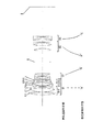
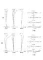
図1は、本発明の第1実施例に係る防振機能を有するマクロレンズのレンズ構成を示す図である。
本実施例に係る防振機能を有するマクロレンズは、図1に示すように、物体側から順に、正の屈折力を有する第1レンズ群G1と、負の屈折力を有する第2レンズ群G2と、開口絞りSと、正の屈折力を有する第3レンズ群G3と、負の屈折力を有する第4レンズ群G4とから構成されている。そして、遠距離から近距離へのフォーカシング(無限遠撮影状態から最近接撮影状態へのフォーカシング)に際して、第1レンズ群G1は固定であり、第1レンズ群G1と第2レンズ群G2との間隔が増大し、第2レンズ群G2と第3レンズ群G3との間隔が減少し、第3レンズ群G3と第4レンズ群G4との間隔が増大するように、第2レンズ群G2、第3レンズ群G3、及び第4レンズ群G4が光軸方向へ移動する。また、開口絞りSは、フォーカシングに際して固定である。
Hereinafter, a macro lens having an image stabilization function according to each embodiment of the present invention will be described in detail with reference to the accompanying drawings.
(First embodiment)
FIG. 1 is a diagram showing a lens configuration of a macro lens having an image stabilization function according to the first embodiment of the present invention.
As shown in FIG. 1, the macro lens having the image stabilization function according to the present embodiment, in order from the object side, a first lens group G1 having a positive refractive power and a second lens group G2 having a negative refractive power. And an aperture stop S, a third lens group G3 having a positive refractive power, and a fourth lens group G4 having a negative refractive power. The first lens group G1 is fixed and the distance between the first lens group G1 and the second lens group G2 during focusing from a long distance to a short distance (focusing from the infinity shooting state to the closest shooting state). Increases, the distance between the second lens group G2 and the third lens group G3 decreases, and the distance between the third lens group G3 and the fourth lens group G4 increases. The lens group G3 and the fourth lens group G4 move in the optical axis direction. The aperture stop S is fixed during focusing.
第1レンズ群G1は、物体側から順に、正の屈折力を有する第1−1レンズ群G11と、正の屈折力を有する第1−2レンズ群G12と、負の屈折力を有する第1−3レンズ群G13とからなる。
第1−1レンズ群G11は、物体側から順に、両凸形状の正レンズL1と、両凸形状の正レンズL2と両凹形状の負レンズL3との接合レンズとからなる。
第1−2レンズ群G12は、物体側から順に、物体側に凸面を向けた負メニスカスレンズL4と、両凸形状の正レンズL5とからなる。
第1−3レンズ群G13は、物体側から順に、物体側に凹面を向けた正メニスカスレンズL6と両凹形状の負レンズL7との接合レンズからなる。
The first lens group G1 includes, in order from the object side, a first lens group G11 having a positive refractive power, a first lens group G12 having a positive refractive power, and a first lens having a negative refractive power. -3 lens group G13.
The first-first lens group G11 includes, in order from the object side, a biconvex positive lens L1, and a cemented lens of a biconvex positive lens L2 and a biconcave negative lens L3.
The first-second lens group G12 includes, in order from the object side, a negative meniscus lens L4 having a convex surface directed toward the object side, and a biconvex positive lens L5.
The first to third lens group G13 includes, in order from the object side, a cemented lens of a positive meniscus lens L6 having a concave surface facing the object side and a biconcave negative lens L7.
第2レンズ群G2は、物体側から順に、物体側に凸面を向けた負メニスカスレンズと、両凹形状の負レンズと物体側に凸面を向けた正メニスカスレンズとの接合レンズとからなる。
第3レンズ群G3は、物体側から順に、両凸形状の正レンズと、両凸形状の正レンズと物体側に凹面を向けた負メニスカスレンズとの接合レンズとからなる。
第4レンズ群G4は、物体側から順に、物体側に凹面を向けた正メニスカスレンズと両凹形状の負レンズとの接合レンズからなる。
そして、本実施例に係る防振機能を有するマクロレンズは、第1−2レンズ群G12を光軸と直交する方向に移動させることによって像面I上の像ぶれを補正する。
The second lens group G2 is composed of, in order from the object side, a negative meniscus lens having a convex surface facing the object side, and a cemented lens of a biconcave negative lens and a positive meniscus lens having a convex surface facing the object side.
The third lens group G3 includes, in order from the object side, a biconvex positive lens, and a cemented lens of a biconvex positive lens and a negative meniscus lens having a concave surface facing the object side.
The fourth lens group G4 includes, in order from the object side, a cemented lens of a positive meniscus lens having a concave surface directed toward the object side and a biconcave negative lens.
The macro lens having the image stabilization function according to the present embodiment corrects the image blur on the image plane I by moving the first-second lens group G12 in a direction orthogonal to the optical axis.
以下の表1に、本発明の第1実施例に係る防振機能を有するマクロレンズの諸元の値を掲げる。
(全体諸元)において、fは焦点距離、FNOはFナンバー、ωは半画角をそれぞれ示す。
(レンズデータ)において、第1カラムの面番号は物体側からのレンズ面の順序、第2カラムのrはレンズ面の曲率半径、第3カラムのdはレンズ面の間隔、第4カラムのνはd線(λ=587.6nm)に対するアッベ数、第5カラムのnはd線(λ=587.6nm)に対する屈折率をそれぞれ示す。また、∞は平面、B.f.はバックフォーカスをそれぞれ示し、空気の屈折率1.0000はその記載を省略している。
Table 1 below lists values of specifications of the macro lens having the image stabilization function according to the first example of the present invention.
In (overall specifications), f represents a focal length, FNO represents an F number, and ω represents a half angle of view.
In (lens data), the surface number of the first column is the order of the lens surface from the object side, r of the second column is the radius of curvature of the lens surface, d of the third column is the distance between the lens surfaces, ν of the fourth column Represents the Abbe number with respect to the d-line (λ = 587.6 nm), and n in the fifth column represents the refractive index with respect to the d-line (λ = 587.6 nm). Further, ∞ represents a plane, Bf represents a back focus, and the refractive index of air is omitted from 1.000.
(フォーカシングデータ)には、無限遠撮影状態、中間距離撮影状態、及び最近接撮影状態における焦点距離f又は撮影倍率M、及び可変間隔の値を示す。D0は物体から第1レンズ面までの距離、Rは物体から像面Iまでの距離、B.f.はバックフォーカスの値をそれぞれ示す。
ここで、以下の各実施例の全ての諸元値において掲載されている焦点距離f、曲率半径r、その他長さの単位は一般に「mm」が使われる。しかし光学系は、比例拡大または比例縮小しても同等の光学性能が得られるため、単位は「mm」に限られるものではない。
なお、以下の全実施例の諸元値においても、本実施例と同様の符号を用いる。
(Focusing data) indicates the focal length f or imaging magnification M and variable interval values in the infinity shooting state, the intermediate distance shooting state, and the closest shooting state. D0 is the distance from the object to the first lens surface, R is the distance from the object to the image plane I, and Bf is the back focus value.
Here, in general, “mm” is used as a unit of the focal length f, the radius of curvature r, and other lengths listed in all the specification values of the following embodiments. However, since the optical system can obtain the same optical performance even when proportionally enlarged or reduced, the unit is not limited to “mm”.
In addition, also in the specification values of all the following examples, the same symbols as in this example are used.
[表1]
(全体諸元)
f =104.827
FNO= 2.85
ω = 11.70°
(レンズデータ)
面番号 r d ν n
1 140.5916 4.3340 46.58 1.804000
2 -304.6651 0.1500
3 54.5339 7.0903 81.61 1.497000
4 -141.0659 1.4000 34.96 1.801000
5 178.5483 1.5000
6 87.9941 1.4000 25.68 1.784720
7 40.9414 0.3802
8 42.5295 5.2680 46.58 1.804000
9 -324.5205 1.5000
10 -274.0591 2.1413 81.61 1.497000
11 -88.0305 1.4000 42.24 1.799520
12 2141.7521 (d12)
13 1611.2683 1.4000 46.58 1.804000
14 33.2052 3.2301
15 -127.8824 1.4000 44.89 1.639300
16 29.3525 3.5793 23.78 1.846660
17 267.1938 (d17)
18 ∞ (d18) 開口絞りS
19 274.8906 3.3516 53.22 1.693500
20 -61.4091 5.2348
21 109.5104 5.0407 46.58 1.804000
22 -41.5391 1.6000 23.78 1.846660
23 -302.2037 (d23)
24 -51.6011 3.1074 23.78 1.846660
25 -30.9388 1.6000 35.30 1.592700
26 247.6195 (B.f.)
(フォーカシングデータ)
無限遠撮影状態 中間距離撮影状態 最近接撮影状態
f/M 104.82690 -0.50000 -0.97000
D0 ∞ 239.4083 149.0777
d12 1.60000 10.97819 20.78241
d17 21.28241 11.90423 2.10000
d18 20.81507 10.08499 4.10180
d23 5.00000 16.49996 32.90816
B.f. 53.19468 52.42478 41.99975
R ∞ 397.40811 307.07749
[Table 1]
(Overall specifications)
f = 104.827
FNO = 2.85
ω = 11.70 °
(Lens data)
Surface number r d v n
1 140.5916 4.3340 46.58 1.804000
2 -304.6651 0.1500
3 54.5339 7.0903 81.61 1.497000
4 -141.0659 1.4000 34.96 1.801000
5 178.5483 1.5000
6 87.9941 1.4000 25.68 1.784720
7 40.9414 0.3802
8 42.5295 5.2680 46.58 1.804000
9 -324.5205 1.5000
10 -274.0591 2.1413 81.61 1.497000
11 -88.0305 1.4000 42.24 1.799520
12 2141.7521 (d12)
13 1611.2683 1.4000 46.58 1.804000
14 33.2052 3.2301
15 -127.8824 1.4000 44.89 1.639300
16 29.3525 3.5793 23.78 1.846660
17 267.1938 (d17)
18 ∞ (d18) Aperture stop S
19 274.8906 3.3516 53.22 1.693500
20 -61.4091 5.2348
21 109.5104 5.0407 46.58 1.804000
22 -41.5391 1.6000 23.78 1.846660
23 -302.2037 (d23)
24 -51.6011 3.1074 23.78 1.846660
25 -30.9388 1.6000 35.30 1.592700
26 247.6195 (Bf)
(Focusing data)
Infinity shooting state Medium distance shooting state Closest shooting state f / M 104.82690 -0.50000 -0.97000
D0 ∞ 239.4083 149.0777
d12 1.60000 10.97819 20.78241
d17 21.28241 11.90423 2.10000
d18 20.81507 10.08499 4.10180
d23 5.00000 16.49996 32.90816
Bf 53.19468 52.42478 41.99975
R ∞ 397.40811 307.07749
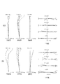
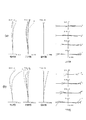
図2(a),(b)は、それぞれ本発明の第1実施例に係る防振機能を有するマクロレンズの無限遠撮影状態における諸収差図、無限遠撮影状態において0.3°の回転ぶれに対するぶれ補正を行ったときのメリディオナル横収差図である。
なお、レンズ全系の焦点距離がfで防振係数がKのレンズによって角度θの回転ぶれを補正するためには、ぶれ補正用の移動レンズ群を(f・tanθ)/Kだけ光軸と直交する方向に移動させればよい。本実施例に係る防振機能を有するマクロレンズにおいては、第1−2レンズ群G12の防振係数を1.00としており、レンズ全系の焦点距離は104.827mmであるため、0.3°の回転ぶれを補正するための第1−2レンズ群G12の移動量は、0.549mmとなる。
図3(a),(b)は、それぞれ本発明の第1実施例に係る防振機能を有するマクロレンズの中間距離撮影撮影状態(撮影倍率-0.5倍)における諸収差図、最近接撮影状態(撮影倍率-0.97倍)における諸収差図である。
FIGS. 2A and 2B are graphs showing various aberrations of the macro lens having the image stabilization function according to the first embodiment of the present invention in an infinite photographing state, and a shake with respect to a rotational shake of 0.3 ° in the infinite photographing state. It is a meridional transverse aberration figure when correct | amending.
In order to correct rotational shake at an angle θ by a lens having a focal length f of the entire lens system and an anti-vibration coefficient K, a moving lens group for shake correction is set to an optical axis by (f · tan θ) / K. What is necessary is just to move to the orthogonal direction. In the macro lens having the image stabilization function according to this example, the image stabilization coefficient of the first-second lens group G12 is set to 1.00, and the focal length of the entire lens system is 104.827 mm. The moving amount of the first-second lens group G12 for correction is 0.549 mm.
FIGS. 3A and 3B are diagrams showing various aberrations in the intermediate distance shooting state (shooting magnification of −0.5 times) of the macro lens having the image stabilization function according to the first embodiment of the present invention, and the closest shooting state. FIG. 6 is a diagram illustrating various aberrations at a photographing magnification of −0.97 times.
各収差図において、FNOはFナンバー、NAは開口数、Yは像高、ωは半画角をそれぞれ示す。尚、球面収差図では最大口径に対応するFナンバーの値又は開口数の最大値を示し、非点収差図及び歪曲収差図では像高の最大値をそれぞれ示し、コマ収差図では各像高の値又は半画角の最大値を示す。また、各収差図において、dはd線(λ=587.6nm)、gはg線(λ=435.8nm)、CはC線(λ=656.3nm)、FはF(λ=486.1nm)の収差曲線をそれぞれ示す。さらに、非点収差図において、実線はサジタル像面、破線はメリディオナル像面をそれぞれ示す。
尚、以下に示す各実施例の諸収差図において、本実施例と同様の符号を用いる。
In each aberration diagram, FNO represents an F number, NA represents a numerical aperture, Y represents an image height, and ω represents a half angle of view. The spherical aberration diagram shows the F-number value or the maximum numerical aperture corresponding to the maximum aperture, the astigmatism diagram and the distortion diagram show the maximum image height, and the coma diagram shows the image height. Indicates the maximum value or half angle of view. In each aberration diagram, d is d-line (λ = 587.6 nm), g is g-line (λ = 435.8 nm), C is C-line (λ = 656.3 nm), and F is F (λ = 486.1 nm). Each aberration curve is shown. Further, in the astigmatism diagram, the solid line indicates the sagittal image plane, and the broken line indicates the meridional image plane.
In addition, in the various aberration diagrams of each example described below, the same reference numerals as those in this example are used.
各諸収差図より本実施例に係る防振機能を有するマクロレンズは、諸収差を良好に補正し、優れた結像性能を有していることがわかる。 From the various aberration diagrams, it can be seen that the macro lens having the image stabilization function according to the present embodiment corrects various aberrations well and has excellent imaging performance.
(第2実施例)
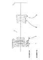
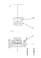
図4は、本発明の第2実施例に係る防振機能を有するマクロレンズのレンズ構成を示す図である。
本実施例に係る防振機能を有するマクロレンズは、図4に示すように、物体側から順に、正の屈折力を有する第1レンズ群G1と、負の屈折力を有する第2レンズ群G2と、開口絞りSと、正の屈折力を有する第3レンズ群G3と、負の屈折力を有する第4レンズ群G4とから構成されている。そして、遠距離から近距離へのフォーカシングに際して、第1レンズ群G1は固定であり、第1レンズ群G1と第2レンズ群G2との間隔が増大し、第2レンズ群G2と第3レンズ群G3との間隔が減少し、第3レンズ群G3と第4レンズ群G4との間隔が増大するよう第2レンズ群G2、第3レンズ群G3、及び第4レンズ群G4が光軸方向へ移動する。また、開口絞りSは、フォーカシングに際して固定である。
(Second embodiment)
FIG. 4 is a diagram showing a lens configuration of a macro lens having an image stabilization function according to the second embodiment of the present invention.
As shown in FIG. 4, the macro lens having the image stabilization function according to the present embodiment, in order from the object side, the first lens group G1 having a positive refractive power and the second lens group G2 having a negative refractive power. And an aperture stop S, a third lens group G3 having a positive refractive power, and a fourth lens group G4 having a negative refractive power. In focusing from a long distance to a short distance, the first lens group G1 is fixed, the distance between the first lens group G1 and the second lens group G2 increases, and the second lens group G2 and the third lens group. The second lens group G2, the third lens group G3, and the fourth lens group G4 are moved in the optical axis direction so that the distance between the third lens group G3 and the fourth lens group G4 is increased. To do. The aperture stop S is fixed during focusing.
第1レンズ群G1は、物体側から順に、正の屈折力を有する第1−1レンズ群G11と、正の屈折力を有する第1−2レンズ群G12と、負の屈折力を有する第1−3レンズ群G13とからなる。
第1−1レンズ群G11は、物体側から順に、両凸形状の正レンズL1と、両凸形状の正レンズL2と両凹形状の負レンズL3との接合レンズとからなる。
第1−2レンズ群G12は、物体側から順に、物体側に凸面を向けた負メニスカスレンズL4と、両凸形状の正レンズL5とからなる。
第1−3レンズ群G13は、物体側から順に、物体側に凹面を向けた正メニスカスレンズL6と物体側に凹面を向けた負メニスカスレンズL7との接合レンズからなる。
The first lens group G1 includes, in order from the object side, a first lens group G11 having a positive refractive power, a first lens group G12 having a positive refractive power, and a first lens having a negative refractive power. -3 lens group G13.
The first-first lens group G11 includes, in order from the object side, a biconvex positive lens L1, and a cemented lens of a biconvex positive lens L2 and a biconcave negative lens L3.
The first-second lens group G12 includes, in order from the object side, a negative meniscus lens L4 having a convex surface directed toward the object side, and a biconvex positive lens L5.
The first to third lens group G13 includes, in order from the object side, a cemented lens of a positive meniscus lens L6 having a concave surface facing the object side and a negative meniscus lens L7 having a concave surface facing the object side.
第2レンズ群G2は、物体側から順に、両凹形状の負レンズと、両凹形状の負レンズと物体側に凸面を向けた正メニスカスレンズとの接合レンズとからなる。
第3レンズ群G3は、物体側から順に、両凸形状の正レンズと、両凸形状の正レンズと両凹形状の負レンズとの接合レンズとからなる。
第4レンズ群G4は、物体側から順に、物体側に凹面を向けた正メニスカスレンズと両凹形状の負レンズとの接合レンズからなる。
そして、本実施例に係る防振機能を有するマクロレンズは、第1−2レンズ群G12を光軸と直交する方向に移動させることによって像面I上の像ぶれを補正する。
以下の表2に、本発明の第2実施例に係る防振機能を有するマクロレンズの諸元の値を掲げる。
The second lens group G2 includes, in order from the object side, a biconcave negative lens, and a cemented lens of a biconcave negative lens and a positive meniscus lens having a convex surface facing the object side.
The third lens group G3 includes, in order from the object side, a biconvex positive lens, and a cemented lens of a biconvex positive lens and a biconcave negative lens.
The fourth lens group G4 includes, in order from the object side, a cemented lens of a positive meniscus lens having a concave surface directed toward the object side and a biconcave negative lens.
The macro lens having the image stabilization function according to the present embodiment corrects the image blur on the image plane I by moving the first-second lens group G12 in a direction orthogonal to the optical axis.
Table 2 below lists values of specifications of the macro lens having the image stabilization function according to the second example of the present invention.
[表2]
(全体諸元)
f =105.000
FNO= 2.85
ω = 11.52°
(レンズデータ)
面番号 r d ν n
1 160.9098 3.2362 46.58 1.804000
2 -287.7316 0.1500
3 65.4186 5.4325 81.61 1.497000
4 -136.0738 1.4000 34.96 1.801000
5 277.8526 1.5000
6 101.9973 1.4000 28.46 1.728250
7 37.4467 0.5916
8 41.0414 5.0321 46.58 1.804000
9 -234.2370 1.5000
10 -214.7813 1.4025 70.24 1.487490
11 -117.6717 1.4000 34.96 1.801000
12 -1063.9287 (d12)
13 -321.8144 1.4000 43.73 1.605620
14 32.4637 3.6142
15 -136.7087 1.4000 59.78 1.522490
16 32.7427 3.1300 23.78 1.846660
17 127.8432 (d17)
18 ∞ (d18) 開口絞りS
19 279.3120 5.5835 46.58 1.804000
20 -67.9776 2.2265
21 105.4067 7.0801 46.58 1.804000
22 -43.3608 1.4000 23.78 1.846660
23 650.5805 (d23)
24 -91.6307 6.7960 25.43 1.805180
25 -29.1696 1.4000 34.96 1.801000
26 630.9231 (B.f.)
(フォーカシングデータ)
無限遠撮影状態 中間距離撮影状態 最近接撮影状態
f/M 104.99987 -0.50000 -0.97000
D0 ∞ 229.8760 134.8999
d12 1.60000 10.95681 21.43967
d17 21.93967 12.58286 2.10000
d18 36.76024 21.92349 14.63106
d23 5.00000 14.84868 32.75400
B.f. 47.62396 52.61194 41.99870
R ∞ 399.87506 304.89861
[Table 2]
(Overall specifications)
f = 105.000
FNO = 2.85
ω = 11.52 °
(Lens data)
Surface number r d v n
1 160.9098 3.2362 46.58 1.804000
2 -287.7316 0.1500
3 65.4186 5.4325 81.61 1.497000
4 -136.0738 1.4000 34.96 1.801000
5 277.8526 1.5000
6 101.9973 1.4000 28.46 1.728250
7 37.4467 0.5916
8 41.0414 5.0321 46.58 1.804000
9 -234.2370 1.5000
10 -214.7813 1.4025 70.24 1.487490
11 -117.6717 1.4000 34.96 1.801000
12 -1063.9287 (d12)
13 -321.8144 1.4000 43.73 1.605620
14 32.4637 3.6142
15 -136.7087 1.4000 59.78 1.522490
16 32.7427 3.1300 23.78 1.846660
17 127.8432 (d17)
18 ∞ (d18) Aperture stop S
19 279.3120 5.5835 46.58 1.804000
20 -67.9776 2.2265
21 105.4067 7.0801 46.58 1.804000
22 -43.3608 1.4000 23.78 1.846660
23 650.5805 (d23)
24 -91.6307 6.7960 25.43 1.805180
25 -29.1696 1.4000 34.96 1.801000
26 630.9231 (Bf)
(Focusing data)
Infinity shooting state Medium distance shooting state Closest shooting state f / M 104.99987 -0.50000 -0.97000
D0 ∞ 229.8760 134.8999
d12 1.60000 10.95681 21.43967
d17 21.93967 12.58286 2.10000
d18 36.76024 21.92349 14.63106
d23 5.00000 14.84868 32.75400
Bf 47.62396 52.61194 41.99870
R ∞ 399.87506 304.89861
図5(a),(b)は、それぞれ本発明の第2実施例に係る防振機能を有するマクロレンズの無限遠撮影状態における諸収差図、無限遠撮影状態において0.3°の回転ぶれに対するぶれ補正を行ったときのメリディオナル横収差図である。
本実施例に係る防振機能を有するマクロレンズにおいては、第1−2レンズ群G12の防振係数を1.00としており、レンズ全系の焦点距離は105.000mmであるため、0.3°の回転ぶれを補正するための第1−2レンズ群G12の移動量は、0.550mmとなる。
図6(a),(b)は、それぞれ本発明の第2実施例に係る防振機能を有するマクロレンズの中間距離撮影撮影状態(撮影倍率-0.5倍)における諸収差図、最近接撮影状態(撮影倍率-0.97倍)における諸収差図である。
各諸収差図より本実施例に係る防振機能を有するマクロレンズは、諸収差を良好に補正し、優れた結像性能を有していることがわかる。
FIGS. 5A and 5B are graphs showing various aberrations in the infinity shooting state of the macro lens having the image stabilization function according to the second embodiment of the present invention. It is a meridional transverse aberration figure when correct | amending.
In the macro lens having the image stabilization function according to this embodiment, the image stabilization coefficient of the first-second lens group G12 is set to 1.00, and the focal length of the entire lens system is 105.000 mm. The moving amount of the first-second lens group G12 for correction is 0.550 mm.
FIGS. 6A and 6B are graphs showing various aberrations in the intermediate distance shooting state (shooting magnification of −0.5 times) of the macro lens having the image stabilization function according to the second embodiment of the present invention, and the closest shooting state. FIG. 6 is a diagram illustrating various aberrations at a photographing magnification of −0.97 times.
From the various aberration diagrams, it can be seen that the macro lens having the image stabilization function according to the present embodiment corrects various aberrations well and has excellent imaging performance.
(第3実施例)
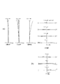
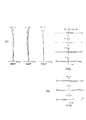
図7は、本発明の第3実施例に係る防振機能を有するマクロレンズのレンズ構成を示す図である。
本実施例に係る防振機能を有するマクロレンズは、図7に示すように、物体側から順に、正の屈折力を有する第1レンズ群G1と、負の屈折力を有する第2レンズ群G2と、開口絞りSと、正の屈折力を有する第3レンズ群G3と、負の屈折力を有する第4レンズ群G4とから構成されている。そして、遠距離から近距離へのフォーカシングに際して、第1レンズ群G1は固定であり、第1レンズ群G1と第2レンズ群G2との間隔が増大し、第2レンズ群G2と第3レンズ群G3との間隔が減少し、第3レンズ群G3と第4レンズ群G4との間隔が増大するように、第2レンズ群G2、第3レンズ群G3、及び第4レンズ群G4が光軸方向へ移動する。また、開口絞りSは、フォーカシングに際して固定である。
(Third embodiment)
FIG. 7 is a diagram showing a lens configuration of a macro lens having an image stabilization function according to the third example of the present invention.
As shown in FIG. 7, the macro lens having the image stabilization function according to the present embodiment, in order from the object side, the first lens group G1 having a positive refractive power and the second lens group G2 having a negative refractive power. And an aperture stop S, a third lens group G3 having a positive refractive power, and a fourth lens group G4 having a negative refractive power. In focusing from a long distance to a short distance, the first lens group G1 is fixed, the distance between the first lens group G1 and the second lens group G2 increases, and the second lens group G2 and the third lens group. The second lens group G2, the third lens group G3, and the fourth lens group G4 are arranged in the optical axis direction so that the distance between the third lens group G3 and the fourth lens group G4 is increased. Move to. The aperture stop S is fixed during focusing.
第1レンズ群G1は、物体側から順に、正の屈折力を有する第1−1レンズ群G11と、正の屈折力を有する第1−2レンズ群G12と、負の屈折力を有する第1−3レンズ群G13とからなる。
第1−1レンズ群G11は、物体側から順に、両凸形状の正レンズL1と、両凸形状の正レンズL2と両凹形状の負レンズL3との接合レンズとからなる。
第1−2レンズ群G12は、物体側から順に、物体側に凸面を向けた正メニスカスレンズ(第1正レンズ)L4と、物体側に凸面を向けた負メニスカスレンズL5と、両凸形状の正レンズ(物体側に凸面を向けた第2正レンズ)L6とからなる。
第1−3レンズ群G13は、物体側に凹面を向けた負メニスカスレンズL7からなる。
The first lens group G1 includes, in order from the object side, a first lens group G11 having a positive refractive power, a first lens group G12 having a positive refractive power, and a first lens having a negative refractive power. -3 lens group G13.
The first-first lens group G11 includes, in order from the object side, a biconvex positive lens L1, and a cemented lens of a biconvex positive lens L2 and a biconcave negative lens L3.
The first-second lens group G12 includes, in order from the object side, a positive meniscus lens (first positive lens) L4 having a convex surface directed toward the object side, a negative meniscus lens L5 having a convex surface directed toward the object side, and a biconvex shape. And a positive lens (second positive lens having a convex surface facing the object side) L6.
The first to third lens group G13 includes a negative meniscus lens L7 having a concave surface directed toward the object side.
第2レンズ群G2は、物体側から順に、両凹形状の負レンズと、両凹形状の負レンズと物体側に凸面を向けた正メニスカスレンズとの接合レンズとからなる。
第3レンズ群G3は、物体側から順に、両凸形状の正レンズと、両凸形状の正レンズと両凹形状の負レンズとの接合レンズとからなる。
第4レンズ群G4は、物体側から順に、物体側に凹面を向けた正メニスカスレンズと両凹形状の負レンズとの接合レンズからなる。
そして、本実施例に係る防振機能を有するマクロレンズは、第1−2レンズ群G12を光軸と直交する方向に移動させることによって像面I上の像ぶれを補正する。
以下の表3に、本発明の第3実施例に係る防振機能を有するマクロレンズの諸元の値を掲げる。
The second lens group G2 includes, in order from the object side, a biconcave negative lens, and a cemented lens of a biconcave negative lens and a positive meniscus lens having a convex surface facing the object side.
The third lens group G3 includes, in order from the object side, a biconvex positive lens, and a cemented lens of a biconvex positive lens and a biconcave negative lens.
The fourth lens group G4 includes, in order from the object side, a cemented lens of a positive meniscus lens having a concave surface directed toward the object side and a biconcave negative lens.
The macro lens having the image stabilization function according to the present embodiment corrects the image blur on the image plane I by moving the first-second lens group G12 in a direction orthogonal to the optical axis.
Table 3 below lists values of specifications of the macro lens having the image stabilization function according to the third example of the present invention.
[表3]
(全体諸元)
f =105.000
FNO= 2.85
ω = 11.66°
(レンズデータ)
面番号 r d ν n
1 147.7879 3.9184 46.58 1.804000
2 -296.1048 0.1500
3 58.5075 6.8986 81.61 1.497000
4 -124.7556 1.4000 39.59 1.804400
5 149.8247 1.5002
6 139.5959 1.6138 81.61 1.497000
7 243.1340 0.1500
8 52.9576 1.4000 29.23 1.721510
9 36.7443 0.5685
10 39.6374 5.5744 81.61 1.497000
11 -164.1215 1.5000
12 -144.5245 1.4000 46.58 1.804000
13 -311.0961 (d13)
14 -276.6564 1.4000 43.73 1.605620
15 29.3712 3.6395
16 -122.5927 1.4000 59.78 1.522490
17 30.4280 2.9973 23.78 1.846660
18 102.9754 (d18)
19 ∞ (d19) 開口絞りS
20 265.2287 5.9186 46.58 1.804000
21 -68.0413 0.1500
22 83.5879 6.6671 46.58 1.804000
23 -47.1455 1.9966 23.78 1.846660
24 312.6115 (d24)
25 -130.3529 6.9050 25.43 1.805180
26 -30.2822 2.2929 34.96 1.801000
27 198.3576 (B.f.)
(フォーカシングデータ)
無限遠撮影状態 中間距離撮影状態 最近接撮影状態
f/M 104.99984 -0.50000 -0.96999
D0 ∞ 234.8315 149.3573
d13 1.60000 12.32979 23.47702
d18 23.97702 13.24724 2.10000
d19 26.84396 18.00242 11.51048
d24 6.78573 18.81333 31.47179
B.f. 51.35180 48.16557 41.99865
R ∞ 404.83055 319.35595
[Table 3]
(Overall specifications)
f = 105.000
FNO = 2.85
ω = 11.66 °
(Lens data)
Surface number r d v n
1 147.7879 3.9184 46.58 1.804000
2 -296.1048 0.1500
3 58.5075 6.8986 81.61 1.497000
4 -124.7556 1.4000 39.59 1.804400
5 149.8247 1.5002
6 139.5959 1.6138 81.61 1.497000
7 243.1340 0.1500
8 52.9576 1.4000 29.23 1.721510
9 36.7443 0.5685
10 39.6374 5.5744 81.61 1.497000
11 -164.1215 1.5000
12 -144.5245 1.4000 46.58 1.804000
13 -311.0961 (d13)
14 -276.6564 1.4000 43.73 1.605620
15 29.3712 3.6395
16 -122.5927 1.4000 59.78 1.522490
17 30.4280 2.9973 23.78 1.846660
18 102.9754 (d18)
19 ∞ (d19) Aperture stop S
20 265.2287 5.9186 46.58 1.804000
21 -68.0413 0.1500
22 83.5879 6.6671 46.58 1.804000
23 -47.1455 1.9966 23.78 1.846660
24 312.6115 (d24)
25 -130.3529 6.9050 25.43 1.805 180
26 -30.2822 2.2929 34.96 1.801000
27 198.3576 (Bf)
(Focusing data)
Infinite shooting mode Intermediate shooting mode Nearest shooting mode f / M 104.99984 -0.50000 -0.96999
D0 ∞ 234.8315 149.3573
d13 1.60000 12.32979 23.47702
d18 23.97702 13.24724 2.10000
d19 26.84396 18.00242 11.51048
d24 6.78573 18.81333 31.47179
Bf 51.35180 48.16557 41.99865
R ∞ 404.83055 319.35595
以下の表4に、上記各実施例に係る防振機能を有するマクロレンズの条件式対応値を掲げる。
[表4]
(条件式対応値)
第1実施例 第2実施例 第3実施例
(1) 0.97 0.97 0.97
(2) 11.70 11.52 11.66
(3) 0.572 0.571 0.571
(4) -0.383 -0.449 -0.381
(5) 0.433 0.478 0.452
(6) -0.913 -0.956 -0.934
(7) 1.468 1.582 1.767
(8) 1.496 1.545 1.510
(9) -2.958 -3.985 -5.616
(10) 20.90 18.12 ---
(11) 0.30252 0.31351 ---
(12) 39.37 35.28 ---
(13) --- --- 52.38
Table 4 below lists values corresponding to the conditional expressions of the macro lens having the image stabilization function according to each of the above examples.
[Table 4]
(Values for conditional expressions)
First Example Second Example Third Example (1) 0.97 0.97 0.97
(2) 11.70 11.52 11.66
(3) 0.572 0.571 0.571
(4) -0.383 -0.449 -0.381
(5) 0.433 0.478 0.452
(6) -0.913 -0.956 -0.934
(7) 1.468 1.582 1.767
(8) 1.496 1.545 1.510
(9) -2.958 -3.985 -5.616
(10) 20.90 18.12 ---
(11) 0.30252 0.31351 ---
(12) 39.37 35.28 ---
(13) --- --- 52.38
図8(a),(b)は、それぞれ本発明の第3実施例に係る防振機能を有するマクロレンズの無限遠撮影状態における諸収差図、無限遠撮影状態において0.3°の回転ぶれに対するぶれ補正を行ったときのメリディオナル横収差図である。
本実施例に係る防振機能を有するマクロレンズにおいては、第1−2レンズ群G12の防振係数を1.00としており、レンズ全系の焦点距離は105.000mmであるため、0.3°の回転ぶれを補正するための第1−2レンズ群G12の移動量は、0.550mmとなる。
図9(a),(b)は、それぞれ本発明の第3実施例に係る防振機能を有するマクロレンズの中間距離撮影撮影状態(撮影倍率-0.5倍)における諸収差図、最近接撮影状態(撮影倍率-0.97倍)における諸収差図である。
各諸収差図より本実施例に係る防振機能を有するマクロレンズは、諸収差を良好に補正し、優れた結像性能を有していることがわかる。
FIGS. 8A and 8B are graphs showing various aberrations in the infinity shooting state of the macro lens having the image stabilization function according to the third embodiment of the present invention. It is a meridional transverse aberration figure when correct | amending.
In the macro lens having the image stabilization function according to this embodiment, the image stabilization coefficient of the first-second lens group G12 is set to 1.00, and the focal length of the entire lens system is 105.000 mm. The moving amount of the first-second lens group G12 for correction is 0.550 mm.
FIGS. 9A and 9B are graphs showing various aberrations in the intermediate distance shooting state (shooting magnification of −0.5 times) of the macro lens having the image stabilization function according to the third embodiment of the present invention, and the closest shooting state. FIG. 6 is a diagram illustrating various aberrations at a photographing magnification of −0.97 times.
From the various aberration diagrams, it can be seen that the macro lens having the image stabilization function according to the present embodiment corrects various aberrations well and has excellent imaging performance.
上記各実施例によれば、フィルム又は固体撮像素子を用いる一眼レフカメラに適し、絶対値が0.5倍より大きい撮影倍率と10度以上の半画角を有し、フォーカシングに際して最も物体側のレンズ群が固定でオートフォーカスに適し、諸収差を良好に補正可能で、光学系の一部を光軸と直交する方向に移動させることによって画像のぶれを補正する防振機能を有するマクロレンズを実現できる。 According to each of the above-described embodiments, it is suitable for a single-lens reflex camera using a film or a solid-state imaging device, has an imaging value with an absolute value larger than 0.5 times and a half angle of view of 10 degrees or more, and is closest to the object side during focusing A macro lens with a vibration-proof function that corrects image blurring by moving a part of the optical system in a direction perpendicular to the optical axis. realizable.
G1 第1レンズ群
G2 第2レンズ群
G3 第3レンズ群
G4 第4レンズ群
G11 第1−1レンズ群
G12 第1−2レンズ群
G13 第1−3レンズ群
S 開口絞り
I 像面
G1 First lens group G2 Second lens group G3 Third lens group G4 Fourth lens group G11 1-1 lens group G12 1-2 lens group G13 1-3 lens group S Aperture stop I Image surface
Claims (10)
遠距離から近距離へのフォーカシングに際して、前記第1レンズ群は光軸方向に固定されており、前記少なくとも2つのレンズ群は移動し、
前記第1レンズ群は、物体側から順に、正の屈折力を有する第1−1レンズ群と、正の屈折力を有する第1−2レンズ群と、負の屈折力を有する第1−3レンズ群とからなり、
前記第1−2レンズ群を光軸と直交する方向へ移動させることによって像面上の像ぶれを補正し、
以下の条件式を満足することを特徴とする防振機能を有するマクロレンズ。
0.5<|M| (M<0)
10<ω
ただし、
M:最近接撮影状態における撮影倍率
ω:無限遠撮影状態における半画角(単位は度) A first lens group having a positive refractive power on the most object side, and at least two lens groups on the image side of the first lens group;
During focusing from a long distance to a short distance, the first lens group is fixed in the optical axis direction, and the at least two lens groups move,
The first lens group includes, in order from the object side, a 1-1 lens group having a positive refractive power, a 1-2 lens group having a positive refractive power, and a first 1-3 having a negative refractive power. Consisting of a lens group,
Correcting the image blur on the image plane by moving the first-1-2 lens group in a direction perpendicular to the optical axis;
A macro lens having an anti-vibration function characterized by satisfying the following conditional expression:
0.5 <| M | (M <0)
10 <ω
However,
M: Shooting magnification in the closest shooting state ω: Half angle of view in infinity shooting state (unit: degrees)
遠距離から近距離へのフォーカシングに際して、前記第1レンズ群は光軸方向に固定されており、前記第1レンズ群と前記第2レンズ群との間隔が増大し、前記第2レンズ群と前記第3レンズ群との間隔が減少し、前記第3レンズ群と前記第4レンズ群との間隔が増大し、
前記第1レンズ群は、物体側から順に、正の屈折力を有する第1−1レンズ群と、正の屈折力を有する第1−2レンズ群と、負の屈折力を有する第1−3レンズ群とからなり、
前記第1−2レンズ群を光軸と直交する方向へ移動させることによって像面上の像ぶれを補正し、
以下の条件式を満足することを特徴とする防振機能を有するマクロレンズ。
0.5<|M| (M<0)
10<ω
ただし、
M:最近接撮影状態における撮影倍率
ω:無限遠撮影状態における半画角(単位は度) In order from the object side, a first lens group having a positive refractive power, a second lens group having a negative refractive power, a third lens group having a positive refractive power, and a fourth lens having a negative refractive power And having a group
During focusing from a long distance to a short distance, the first lens group is fixed in the optical axis direction, the distance between the first lens group and the second lens group is increased, and the second lens group and the The distance between the third lens group decreases, the distance between the third lens group and the fourth lens group increases,
The first lens group includes, in order from the object side, a 1-1 lens group having a positive refractive power, a 1-2 lens group having a positive refractive power, and a first 1-3 having a negative refractive power. Consisting of a lens group,
Correcting the image blur on the image plane by moving the first-1-2 lens group in a direction perpendicular to the optical axis;
A macro lens having an anti-vibration function characterized by satisfying the following conditional expression:
0.5 <| M | (M <0)
10 <ω
However,
M: Shooting magnification in the closest shooting state ω: Half angle of view in infinity shooting state (unit: degrees)
0.45<f1/f<0.65
−0.55<f2/f<−0.30
0.35<f3/f<0.55
−1.30<f4/f<−0.85
ただし、
f :無限遠合焦状態における前記マクロレンズ全系の焦点距離
f1:前記第1レンズ群の焦点距離
f2:前記第2レンズ群の焦点距離
f3:前記第3レンズ群の焦点距離
f4:前記第4レンズ群の焦点距離 The macro lens having the image stabilization function according to claim 2, wherein the following conditional expression is satisfied.
0.45 <f1 / f <0.65
−0.55 <f2 / f <−0.30
0.35 <f3 / f <0.55
−1.30 <f4 / f <−0.85
However,
f: focal length of the entire macro lens system in an infinitely focused state f1: focal length of the first lens group f2: focal length of the second lens group f3: focal length of the third lens group f4: the first Focal length of 4 lens groups
1.30<f1−1/f1<1.90
1.30<f1−2/f1<1.70
−6.00<f1−3/f1<−2.50
ただし、
f1 :前記第1レンズ群の焦点距離
f1−1:前記第1−1レンズ群の焦点距離
f1−2:前記第1−2レンズ群の焦点距離
f1−3:前記第1−3レンズ群の焦点距離 The macro lens having the image stabilization function according to claim 1, wherein the following conditional expression is satisfied.
1.30 <f1-1 / f1 <1.90
1.30 <f1-2 / f1 <1.70
-6.00 <f1-3 / f1 <-2.50
However,
f1: focal length f1-1 of the first lens group f1-1: focal length of the 1-1 lens group f1-2: focal length of the 1-2 lens group f1-3: of the 1-3 lens group Focal length
以下の条件式を満足することを特徴とする請求項1又は請求項2に記載の防振機能を有するマクロレンズ。
15<ν12p−ν12n
ただし、
ν12p:前記第1−2レンズ群における前記正レンズの硝材のd線(λ=587.6nm)に対するアッベ数
ν12n:前記第1−2レンズ群における前記負メニスカスレンズの硝材のd線(λ=587.6nm)に対するアッベ数 The 1-2 lens group includes, in order from the object side, a negative meniscus lens having a convex surface facing the object side, and a positive lens having a convex surface facing the object side.
The macro lens having the image stabilization function according to claim 1, wherein the following conditional expression is satisfied.
15 <ν12p−ν12n
However,
ν12p: Abbe number with respect to the d-line (λ = 587.6 nm) of the glass material of the positive lens in the 1-2 lens group ν12n: d-line of the glass material of the negative meniscus lens in the 1-2 lens group (λ = Abbe number for 587.6 nm)
以下の条件式を満足することを特徴とする請求項6に記載の防振機能を有するマクロレンズ。
0.25<N13n−N13p
25<ν13p−ν13n
ただし、
N13n:前記第1−3レンズ群における前記負レンズの硝材のd線(λ=587.6nm)に対する屈折率
N13p:前記第1−3レンズ群における前記正メニスカスレンズの硝材のd線(λ=587.6nm)に対する屈折率
ν13p:前記第1−3レンズ群における前記正メニスカスレンズの硝材のd線(λ=587.6nm)に対するアッベ数
ν13n:前記第1−3レンズ群における前記負レンズの硝材のd線(λ=587.6nm)に対するアッベ数 The first to third lens groups include, in order from the object side, a cemented lens of a positive meniscus lens having a concave surface facing the object side and a negative lens having a concave surface facing the object side.
The macro lens having an image stabilization function according to claim 6, wherein the following conditional expression is satisfied.
0.25 <N13n-N13p
25 <ν13p−ν13n
However,
N13n: Refractive index with respect to d-line (λ = 587.6 nm) of the glass material of the negative lens in the 1-3 lens group N13p: d-line of the glass material of the positive meniscus lens in the 1-3 lens group (λ = Refractive index ν13p with respect to 587.6 nm): Abbe number ν13n with respect to d-line (λ = 587.6 nm) of the glass material of the positive meniscus lens in the first to third lens group: the negative lens in the first to third lens group Abbe number for d-line (λ = 587.6 nm) of glass material
以下の条件式を満足することを特徴とする請求項1又は請求項2に記載の防振機能を有するマクロレンズ。
15<ν12p2−ν12n
ただし、
ν12p2:前記第1−2レンズ群における前記第2正レンズの硝材のd線(λ=587.6nm)に対するアッベ数
ν12n :前記第1−2レンズ群における前記負メニスカスレンズの硝材のd線(λ=587.6nm)に対するアッベ数 The 1-2 lens group includes, in order from the object side, a first positive lens, a negative meniscus lens having a convex surface facing the object side, and a second positive lens having a convex surface facing the object side.
The macro lens having the image stabilization function according to claim 1, wherein the following conditional expression is satisfied.
15 <ν12p2−ν12n
However,
ν12p2: Abbe number with respect to d-line (λ = 587.6 nm) of the glass material of the second positive lens in the 1-2 lens group, ν12n: d-line of the glass material of the negative meniscus lens in the 1-2 lens group ( Abbe number for λ = 587.6 nm)
Priority Applications (1)
| Application Number | Priority Date | Filing Date | Title |
|---|---|---|---|
| JP2004105429A JP2005292345A (en) | 2004-03-31 | 2004-03-31 | Macro lens with anti-vibration function |
Applications Claiming Priority (1)
| Application Number | Priority Date | Filing Date | Title |
|---|---|---|---|
| JP2004105429A JP2005292345A (en) | 2004-03-31 | 2004-03-31 | Macro lens with anti-vibration function |
Publications (1)
| Publication Number | Publication Date |
|---|---|
| JP2005292345A true JP2005292345A (en) | 2005-10-20 |
Family
ID=35325357
Family Applications (1)
| Application Number | Title | Priority Date | Filing Date |
|---|---|---|---|
| JP2004105429A Withdrawn JP2005292345A (en) | 2004-03-31 | 2004-03-31 | Macro lens with anti-vibration function |
Country Status (1)
| Country | Link |
|---|---|
| JP (1) | JP2005292345A (en) |
Cited By (4)
| Publication number | Priority date | Publication date | Assignee | Title |
|---|---|---|---|---|
| US8681435B2 (en) | 2009-10-28 | 2014-03-25 | Samsung Electronics Co., Ltd. | Macro lens system and pickup device including the same |
| KR101431539B1 (en) * | 2008-01-11 | 2014-08-19 | 삼성전자주식회사 | Zoom lens system |
| JP2015215391A (en) * | 2014-05-08 | 2015-12-03 | キヤノン株式会社 | Optical system and imaging device including the same |
| US9417430B2 (en) | 2012-07-20 | 2016-08-16 | Panasonic Intellectual Property Management Co., Ltd. | Inner focus lens system, interchangeable lens apparatus and camera system |
-
2004
- 2004-03-31 JP JP2004105429A patent/JP2005292345A/en not_active Withdrawn
Cited By (4)
| Publication number | Priority date | Publication date | Assignee | Title |
|---|---|---|---|---|
| KR101431539B1 (en) * | 2008-01-11 | 2014-08-19 | 삼성전자주식회사 | Zoom lens system |
| US8681435B2 (en) | 2009-10-28 | 2014-03-25 | Samsung Electronics Co., Ltd. | Macro lens system and pickup device including the same |
| US9417430B2 (en) | 2012-07-20 | 2016-08-16 | Panasonic Intellectual Property Management Co., Ltd. | Inner focus lens system, interchangeable lens apparatus and camera system |
| JP2015215391A (en) * | 2014-05-08 | 2015-12-03 | キヤノン株式会社 | Optical system and imaging device including the same |
Similar Documents
| Publication | Publication Date | Title |
|---|---|---|
| JP4857576B2 (en) | Zoom lens | |
| JP5475401B2 (en) | Large-aperture telephoto zoom lens with anti-vibration function | |
| JP5648907B2 (en) | Magnification optical system and optical instrument | |
| JP5176410B2 (en) | Variable magnification optical system, optical apparatus, and variable magnification optical system magnification method | |
| JP4356040B2 (en) | Long zoom lens with anti-vibration function | |
| JP2013097212A (en) | Inner focus type telephoto lens | |
| JP3858305B2 (en) | Image position correction optical system | |
| JP2009014766A (en) | Variable magnification optical system, optical apparatus, and variable magnification optical system magnification method | |
| JP4635688B2 (en) | Zoom lens with anti-vibration function | |
| WO2013146758A1 (en) | Optical zoom system, optical device, and method for manufacturing zoom optical system | |
| JP4120647B2 (en) | Zoom lens with anti-vibration function | |
| JP2018097101A (en) | Imaging lens and imaging apparatus | |
| JP5544926B2 (en) | Photographic lens, optical apparatus having the photographic lens, and method of manufacturing the photographic lens | |
| JP5157295B2 (en) | Optical system, imaging device, and optical system imaging method | |
| JP5648900B2 (en) | Variable magnification optical system and optical apparatus having the variable magnification optical system | |
| JP6152641B2 (en) | Zoom lens system and electronic imaging apparatus including the same | |
| JP2014098794A (en) | Variable power optical system, optical device, and method for manufacturing the variable power optical system | |
| JP2015215557A (en) | Optical system, optical device, and method for manufacturing the optical system | |
| JPH0727975A (en) | Rear conversion lens with anti-vibration function | |
| JP2014098795A (en) | Variable power optical system, optical device, and method for manufacturing the variable power optical system | |
| JP2005292338A (en) | Zoom lens | |
| JP5958018B2 (en) | Zoom lens, imaging device | |
| JP2020086159A (en) | Optical system, optical device, and method of manufacturing optical system | |
| WO2014077120A1 (en) | Variable power optical assembly, optical device, and variable power optical assembly fabrication method | |
| JP4905429B2 (en) | Zoom lens |
Legal Events
| Date | Code | Title | Description |
|---|---|---|---|
| A300 | Withdrawal of application because of no request for examination |
Free format text: JAPANESE INTERMEDIATE CODE: A300 Effective date: 20070605 |