EP3640481A1 - Vakuumpumpe - Google Patents
Vakuumpumpe Download PDFInfo
- Publication number
- EP3640481A1 EP3640481A1 EP18200472.1A EP18200472A EP3640481A1 EP 3640481 A1 EP3640481 A1 EP 3640481A1 EP 18200472 A EP18200472 A EP 18200472A EP 3640481 A1 EP3640481 A1 EP 3640481A1
- Authority
- EP
- European Patent Office
- Prior art keywords
- pump
- stator
- rotor
- shield
- sleeve
- Prior art date
- Legal status (The legal status is an assumption and is not a legal conclusion. Google has not performed a legal analysis and makes no representation as to the accuracy of the status listed.)
- Granted
Links
Images



Classifications
-
- F—MECHANICAL ENGINEERING; LIGHTING; HEATING; WEAPONS; BLASTING
- F04—POSITIVE - DISPLACEMENT MACHINES FOR LIQUIDS; PUMPS FOR LIQUIDS OR ELASTIC FLUIDS
- F04D—NON-POSITIVE-DISPLACEMENT PUMPS
- F04D19/00—Axial-flow pumps
- F04D19/02—Multi-stage pumps
- F04D19/04—Multi-stage pumps specially adapted to the production of a high vacuum, e.g. molecular pumps
- F04D19/042—Turbomolecular vacuum pumps
-
- F—MECHANICAL ENGINEERING; LIGHTING; HEATING; WEAPONS; BLASTING
- F04—POSITIVE - DISPLACEMENT MACHINES FOR LIQUIDS; PUMPS FOR LIQUIDS OR ELASTIC FLUIDS
- F04D—NON-POSITIVE-DISPLACEMENT PUMPS
- F04D19/00—Axial-flow pumps
- F04D19/02—Multi-stage pumps
- F04D19/04—Multi-stage pumps specially adapted to the production of a high vacuum, e.g. molecular pumps
- F04D19/048—Multi-stage pumps specially adapted to the production of a high vacuum, e.g. molecular pumps comprising magnetic bearings
-
- F—MECHANICAL ENGINEERING; LIGHTING; HEATING; WEAPONS; BLASTING
- F04—POSITIVE - DISPLACEMENT MACHINES FOR LIQUIDS; PUMPS FOR LIQUIDS OR ELASTIC FLUIDS
- F04D—NON-POSITIVE-DISPLACEMENT PUMPS
- F04D29/00—Details, component parts, or accessories
- F04D29/02—Selection of particular materials
- F04D29/023—Selection of particular materials especially adapted for elastic fluid pumps
-
- F—MECHANICAL ENGINEERING; LIGHTING; HEATING; WEAPONS; BLASTING
- F04—POSITIVE - DISPLACEMENT MACHINES FOR LIQUIDS; PUMPS FOR LIQUIDS OR ELASTIC FLUIDS
- F04D—NON-POSITIVE-DISPLACEMENT PUMPS
- F04D29/00—Details, component parts, or accessories
- F04D29/05—Shafts or bearings, or assemblies thereof, specially adapted for elastic fluid pumps
- F04D29/056—Bearings
- F04D29/058—Bearings magnetic; electromagnetic
-
- F—MECHANICAL ENGINEERING; LIGHTING; HEATING; WEAPONS; BLASTING
- F05—INDEXING SCHEMES RELATING TO ENGINES OR PUMPS IN VARIOUS SUBCLASSES OF CLASSES F01-F04
- F05D—INDEXING SCHEME FOR ASPECTS RELATING TO NON-POSITIVE-DISPLACEMENT MACHINES OR ENGINES, GAS-TURBINES OR JET-PROPULSION PLANTS
- F05D2240/00—Components
- F05D2240/50—Bearings
- F05D2240/51—Magnetic
- F05D2240/511—Magnetic with permanent magnets
-
- F—MECHANICAL ENGINEERING; LIGHTING; HEATING; WEAPONS; BLASTING
- F05—INDEXING SCHEMES RELATING TO ENGINES OR PUMPS IN VARIOUS SUBCLASSES OF CLASSES F01-F04
- F05D—INDEXING SCHEME FOR ASPECTS RELATING TO NON-POSITIVE-DISPLACEMENT MACHINES OR ENGINES, GAS-TURBINES OR JET-PROPULSION PLANTS
- F05D2300/00—Materials; Properties thereof
- F05D2300/50—Intrinsic material properties or characteristics
- F05D2300/507—Magnetic properties
Definitions
- the invention relates to a vacuum pump according to the preamble of claim 1.
- it relates to a turbomolecular pump for generating a high vacuum or an even higher vacuum.
- vacuum pumps have to deal with magnetic fields. They are disruptive in different aspects. Since, on the one hand, vacuum pumps run at very high speeds, even weak external magnetic fields in rotating pump components cause eddy currents that heat up the components and act as brakes, so that increased drive power must be reacted to.
- at least one bearing of the pump shaft is often designed as a permanent magnet bearing in order to enable contact-free and thus non-contaminating mounting of a shaft end of the pump rotor.
- Such magnetic bearings have strong magnets (permanent magnets), which act internally and externally and can have undesirable effects there, possibly internally again the inductive effects described.
- a pump according to the preamble of claim 1 is known from the EP 3 034 881 A1 known.
- a vacuum pump is specified there, which has a shield housing surrounding the conventional pump housing.
- a characteristic of this design is that the externally attached shield housing is mechanically comparative be stable and therefore comparatively strong. It therefore contributes to the enlargement of the overall structure.
- the EP 1 669 608 A2 describes a vacuum pump in which a splinterguard is made in the opening of the intake flange from a material with high relative permeability in order to effect a magnetic decoupling.
- a characteristic of this type of construction is that the magnetic shielding does not take place in the radial direction.
- EP 17 187 569 describes an adjusting ring for the axial alignment of a bearing section of a bearing.
- a radially extending part of the setting ring can be designed as a magnetic shield.
- areas of the opening are covered in the axial direction, while no shielding is carried out in the radial direction.
- An object of the invention is to provide a vacuum pump which has good magnetic shielding, which largely leaves the size of the pump unchanged.
- a vacuum pump with a housing and rotatable pump-effective components is specified. It is shielded from magnetic fields.
- the shield lies in the interior of the housing and can completely or partially surround / cover a magnetic bearing, in particular permanent bearing of the pump rotor viewed in the circumferential direction and / or viewed in the axial direction, or can even completely viewed the pump rotor and the pump stator in the axial and / or radial direction or partially cover. Because the shield is provided in the interior of the housing, it can be made comparatively filigree / thin, since it is in any case already protected from external influences by the regular pump housing. Depending on the embodiment, it does not even have to be self-supporting.
- shielding goals can be pursued.
- One is to reduce the external influence of the magnets of the magnetic bearing by adequately shielding the magnetic bearing from the outside, by completely or at least partially covering its components when viewed in the radial direction (viewed in the axial or circumferential direction).
- Another or different goal can be to weaken the magnetic fields acting on the inside of the pump from the outside in order to reduce the above-mentioned inductive effects (eddy current with heat generation and braking effect).
- Another and / or different goal can be to reduce the effect of the magnetic field of the magnetic bearing inside the pump on the rotating parts in the pump.
- the shield viewed in the radial direction, can lie within components of the pump stator, and / or, viewed in the radial direction, can again lie outside the pump rotor and outside the pump stator.
- One possibility is to apply a shield to the inner wall of the outer housing in a sleeve-like manner, which at least partially and preferably completely rotates in the circumferential direction around the inner circumference of the housing and which is considered to be necessary in the axial direction, the internal pump components (magnetic bearing, pump stator, pump rotor,. ..) completely or at least partially covered.
- the shield can be designed to be self-supporting as a stable sleeve which is inserted into the interior of the housing at a suitable time during the manufacture of the pump.
- the outer surface of this sleeve can be designed to be form-fitting / complementary to the inner surface of the housing.
- the sleeve can also have a radially inwardly directed collar in the region of the pump inlet.
- stator-Holweck sleeve which is possibly provided, can also be constructed with a shielding material.
- the shielding can be constructed in several layers and can in particular have a carrier layer and a shielding layer.
- the carrier layer can have desired properties with regard to mechanical stability, resistance and strength.
- the carrier layer can be self-supporting, that is to say in such a way that it is an intrinsically stable molded body that can be handled separately in the desired shape.
- the shielding layer can be applied to the carrier layer and fastened to it.
- the shielding layer can also be self-supporting, but it does not have to, since it is supported by the carrier layer.
- the shielding layer has the features necessary to effect the desired magnetic shielding.
- the shielding can, however, also be a film-like, flexible material that can also be multi-layered and in turn can have a shielding layer and a carrier layer.
- the carrier layer can be a plastic or the like.
- the shield can be prefabricated and then installed in the pump to be manufactured at a suitable time. It can have glue points or adhesive surfaces so that it can be glued.
- the shield or the shielding layer preferably has a metallic material which brings about a desired magnetic shielding.
- the material can be a metallic alloy and predominantly comprise nickel, for example mu-metal, or it can be an alloy with predominantly cobalt (at least 30% by weight cobalt, preferably at least 50% by weight cobalt), in particular Vitrovac®.
- the shielding material can be a material of high relative magnetic permeability ⁇ r. The relative magnetic permeability can be over 1000 or over 3000 or over 10,000 or over 30,000.
- the thickness of the shield or shielding layer can be - depending on the material and / or need - from about 0.02 mm to several millimeters (e.g. 1 to 10 mm for metal or steel) or even several centimeters (e.g. 1 to 3 cm).
- the shielding can be designed with the selectable parameters (e.g. material, thickness) in order to dampen the magnetic fields to below 50% or below 25% or below 10%.
- the shield or the shielding layer preferably also has sufficient electrical conductivity. It is preferably at least 1% of the conductivity of copper. However, it can also be higher and in a range of over 10% or over 20% or over 50% of the conductivity of copper.
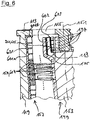
- FIG. 6 shows the possible construction of a vacuum pump 111 in the 1 to 5 .
- the description is made here without the representation of the shield.
- the shielding options are in Fig. 6 shown in combination. These possibilities are considered with the characteristics of 1 to 5 can be combined to understand.
- Fig. 7 shows the possible structure of a shield, which in turn as with the characteristics of Fig. 6 and the 1 to 5 can be understood in combination.
- the turbomolecular pump 111 shown comprises a pump inlet 115 surrounded by an inlet flange 113, to which a recipient, not shown, can be connected in a manner known per se.
- the gas from the recipient can be sucked out of the recipient via the pump inlet 115 and conveyed through the pump to a pump outlet 117, to which a backing pump, such as a rotary vane pump, can be connected.
- the inlet flange 113 forms in accordance with the orientation of the vacuum pump Fig. 1 the upper end of the housing 119 of the vacuum pump 111.
- the housing 119 comprises a lower part 121, on which an electronics housing 123 is arranged on the side. Electrical and / or electronic components of the vacuum pump 111 are accommodated in the electronics housing 123, for example for operating an electric motor 125 arranged in the vacuum pump.
- Several connections 127 for accessories are provided on the electronics housing 123.
- a data interface 129 for example in accordance with the RS485 standard, and a power supply connection 131 are arranged on the electronics housing 123.
- a flood inlet 133 in particular in the form of a flood valve, is provided on the housing 119 of the turbomolecular pump 111, via which the vacuum pump 111 can be flooded.
- a sealing gas connection 135, which is also referred to as a purge gas connection via which purge gas to protect the electric motor 125 (see, for example, FIG Fig. 3 ) can be brought in front of the gas conveyed by the pump into the engine compartment 137, in which the electric motor 125 is accommodated in the vacuum pump 111.
- two coolant connections 139 are arranged in the lower part 121, one of the coolant connections being provided as an inlet and the other coolant connection being provided as an outlet for coolant, which can be guided into the vacuum pump for cooling purposes.
- the lower side 141 of the vacuum pump can serve as a standing surface, so that the vacuum pump 111 can be operated standing on the underside 141.
- the vacuum pump 111 can also be attached to a recipient via the inlet flange 113 and can thus be operated in a manner of hanging.
- the vacuum pump 111 can be designed so that it can also be operated if it is aligned in a different way than in FIG Fig. 1 is shown.
- Embodiments of the vacuum pump can also be realized, in which the underside 141 cannot be arranged facing downwards, but turned to the side or directed upwards.
- various screws 143 are also arranged, by means of which components of the vacuum pump which are not further specified here are fastened to one another.
- a bearing cover 145 is attached to the underside 141.
- Fastening bores 147 are also arranged on the underside 141, via which the pump 111 can be fastened, for example, to a support surface.
- a coolant line 148 is shown in which the coolant introduced and discharged via the coolant connections 139 can circulate.
- the vacuum pump comprises a plurality of process gas pump stages for conveying the process gas present at the pump inlet 115 to the pump outlet 117.
- a rotor (also referred to as a "pump rotor") 149 is arranged in the housing 119 and has a rotor shaft 153 which can be rotated about an axis of rotation 151.
- the turbomolecular pump 111 comprises a plurality of turbomolecular pump stages connected in series with one another in a pumping manner, with a plurality of radial rotor disks 155 fastened to the rotor shaft 153 and stator disks 157 arranged between the rotor disks 155 and fixed in the housing 119 (together also referred to as "pump stator 157").
- a rotor disk 155 and an adjacent stator disk 157 each form a turbomolecular pump stage.
- the stator disks 157 are held at a desired axial distance from one another by spacer rings 159.
- the vacuum pump also comprises Holweck pump stages which are arranged one inside the other in the radial direction and have a pumping effect and are connected in series with one another.
- the rotor of the Holweck pumping stages comprises a rotor hub 161 arranged on the rotor shaft 153 and two cylindrical jacket-shaped Holweck rotor sleeves 163, 165 fastened to and supported by the rotor hub 161, which are coaxial to the axis of rotation 151 oriented and nested in the radial direction.
- two cylindrical jacket-shaped Holweck stator sleeves 167, 169 are provided, which are also oriented coaxially to the axis of rotation 151 and are nested one inside the other in the radial direction.
- the pump-active surfaces of the Holweck pump stages are formed by the lateral surfaces, that is to say by the radial inner and / or outer surfaces, of the Holweck rotor sleeves 163, 165 and of the Holweck stator sleeves 167, 169.
- the radial inner surface of the outer Holweck stator sleeve 167 lies opposite the radial outer surface of the outer Holweck rotor sleeve 163, forming a radial Holweck gap 171 and forms the first Holweck pumping stage following the turbomolecular pumps.
- the radial inner surface of the outer Holweck rotor sleeve 163 faces the radial outer surface of the inner Holweck stator sleeve 169 with the formation of a radial Holweck gap 173 and forms a second Holweck pump stage with the latter.
- the radial inner surface of the inner Holweck stator sleeve 169 lies opposite the radial outer surface of the inner Holweck rotor sleeve 165, forming a radial Holweck gap 175, and forms the third Holweck pump stage with the latter.
- a radially extending channel can be provided, via which the radially outer Holweck gap 171 is connected to the central Holweck gap 173.
- a radially extending channel can be provided at the upper end of the inner Holweck stator sleeve 169, via which the central Holweck gap 173 is connected to the radially inner Holweck gap 175.
- a connection channel 179 to the outlet 117 can also be provided.
- the aforementioned pump-active surfaces of the Holweck stator sleeves 163, 165 each have a plurality of Holweck grooves running spirally around the axis of rotation 151 in the axial direction, while the opposite lateral surfaces of the Holweck rotor sleeves 163, 165 are smooth and the gas for operating the Drive the vacuum pump 111 in the Holweck grooves.
- a roller bearing 181 is provided in the area of the pump outlet 117 and a permanent magnet bearing 183 in the area of the pump inlet 115.
- a conical spray nut 185 is provided on the rotor shaft 153 with an outer diameter increasing toward the roller bearing 181.
- the injection nut 185 is in sliding contact with at least one scraper of an operating fluid reservoir.
- the operating medium storage comprises a plurality of absorbent disks 187 stacked one on top of the other, which are provided with an operating medium for the rolling bearing 181, e.g. are soaked with a lubricant.
- the operating medium is transferred by capillary action from the operating medium storage via the wiper to the rotating spray nut 185 and, as a result of the centrifugal force along the spray nut 185, is conveyed in the direction of the increasing outer diameter of the spray nut 185 to the roller bearing 181, where it e.g. fulfills a lubricating function.
- the roller bearing 181 and the operating fluid reservoir are enclosed in the vacuum pump by a trough-shaped insert 189 and the bearing cover 145.
- the permanent magnet bearing 183 can comprise a rotor-side bearing half 191 and a stator-side bearing half 193, each of which comprises an annular stack of a plurality of permanent magnetic rings 195, 197 stacked on top of one another in the axial direction.
- the ring magnets 195, 197 lie opposite one another to form a radial bearing gap 199, the ring magnets on the rotor side 195 radially outside and the stator-side ring magnets 197 are arranged radially inside.
- the magnetic field present in the bearing gap 199 causes magnetic repulsive forces between the ring magnets 195, 197, which cause the rotor shaft 153 to be supported radially.
- the ring magnets 195 on the rotor side are carried by a carrier section 201 of the rotor shaft 153, which can be designed to be sleeve-shaped all the way round and hold the ring magnets 195 radially on the outside and possibly surround them.
- the stator-side ring magnets 197 are carried by a stator-side carrier section 203 which extends through the ring magnets 197 and is suspended from radial struts 205 of the housing 119.
- Parallel to the axis of rotation 151, the rotor-side ring magnets 195 are fixed by a cover element 207 coupled to the carrier section 203.
- the stator-side ring magnets 197 are fixed parallel to the axis of rotation 151 in one direction by a fastening ring 209 connected to the carrier section 203 and a fastening ring 211 connected to the carrier section 203.
- a plate spring 213 can also be provided between the fastening ring 211 and the ring magnet 197.
- An emergency or catch bearing 215 is provided within the magnetic bearing, which runs empty without contact during normal operation of the vacuum pump 111 and only comes into engagement with an excessive radial deflection of the rotor 149 relative to the stator in order to provide a radial stop for the rotor 149 to form, since a collision of the rotor-side structures with the stator-side structures is prevented.
- the catch bearing 215 is designed as an unlubricated roller bearing and forms a radial gap with the rotor 149 and / or the stator, which causes the catch bearing 215 to be disengaged in normal pumping operation.
- the radial deflection at which the catch bearing 215 engages is dimensioned large enough that the catch bearing 215 does not engage during normal operation of the vacuum pump, and at the same time is small enough so that the rotor-side structures collide with the stator-side structures under all circumstances is prevented.
- the vacuum pump 111 comprises the electric motor 125 for rotatingly driving the rotor 149.
- the armature of the electric motor 125 is formed by the rotor 149, the rotor shaft 153 of which extends through the motor stator 217.
- a permanent magnet arrangement can be arranged radially on the outside or embedded on the section of the rotor shaft 153 which extends through the motor stator 217.
- an intermediate space 219 is arranged which comprises a radial motor gap, via which the motor stator 217 and the permanent magnet arrangement for transmitting the drive torque can magnetically influence one another.
- the motor stator 217 is fixed in the housing within the motor space 137 provided for the electric motor 125.
- a sealing gas which is also referred to as a purge gas and which can be, for example, air or nitrogen, can enter the engine compartment 137 via the sealing gas connection 135.
- the electric motor 125 can be used before the process gas, e.g. protected against corrosive parts of the process gas.
- the engine compartment 137 can also be evacuated via the pump outlet 117, i.e. in the engine compartment 137 there is at least approximately the vacuum pressure caused by the backing pump connected to the pump outlet 117.
- a so-called labyrinth seal 223, which is known per se, can also be provided between the rotor hub 161 and a wall 221 delimiting the motor space 137, in particular in order to achieve a better seal of the motor space 217 with respect to the radially outside Holweck pump stages.
- Fig. 6 shows schematized and simplified what is similar in Fig. 3 was shown, but with installation options for the above-mentioned shielding.
- the shields of the Fig. 6 are designated by the reference numerals 601 to 605. As already mentioned above, a single one of these shields can be provided, or several of the shields can be provided in combination with one another.
- the shield can be designed as a self-supporting component or as a non-self-supporting component or as a coating. It can be a suitably shaped surface-rigid material, for example a sheet metal, or a sheet-like material or a coating applied at the locations shown by suitable methods.
- the component or coating is made with the desired material and thickness.
- a shield is designated, which rests on the inner circumference of the housing 119. It can be a self-supporting stable sleeve or can be a less stable structure that is glued or otherwise suitably attached to the inner surface of the housing 119. You can, as in Fig. 6 indicated, largely completely cover the inside of the pump in the axial direction. However, if, for example, only the magnetic bearing is to be shielded, it can also be provided (viewed in the axial direction) only in the region of the magnetic bearing.
- the degree of coverage of the magnetic bearing with the shield viewed in the axial direction can have a lower limit of 80% of its axial length or 90% or 100% or 110% and / or an upper limit of 90% or 95% or 100% or 110 % or 120% or 150%.
- the shield 601 preferably runs completely around the circumference.
- Shield 601 can be a stable sleeve. It can have a cylindrical part, which in Fig. 6 601a from bottom to top. It can furthermore have a radially extending part (collar) 601b attached to one axial end of the cylindrical part 601a, which extends radially inward from the cylindrical part 601a and approximately still covers the flange 113 of the pump inside.
- the radial extension inward of the collar 601b can be such that the opening 115 of the pump remains essentially uncovered.
- the collar 601b (not shown) can extend inward beyond the radially inner boundary of the opening 115.
- the Fig. 6 schematically shows the pumping stages of radially extending stator and rotor elements, which are covered by the shield 601. However, it can also or instead be drawn so far that it also covers a Holweck stator sleeve 167, 169 radially on the outside.
- a Holweck sleeve 167, 169 is provided, this can also be made of magnetic shielding material itself and then be installed in a suitable manner. This is then preferably done with the radially outermost Holweck sleeve, which is usually a stator sleeve.
- Fig. 6 also shows as an option that spacer rings 159, 604 can be built as a shield by being made of a suitable shielding material.
- the spacer rings 159, 604 take up a noticeable portion of the length, generally over 70% or over 80%, so that 70 to 80% of the length can be magnetically shielded by appropriate design of these rings. Since the rings also have a certain thickness, the shielding can be designed according to the thickness.
- the shields 601 and 604 described so far are largely outside the stator and rotor components. But it is also possible to use the shielding viewed radially within rotor components. In Fig. 6 this is shown with reference numerals 602, 603 and 605.
- Reference numbers 201, 605 show the holder for the radially outer magnetic rings 195 of the magnetic bearing. As a rule, these are the magnetic rings of the rotor-side bearing half, while the rings 197 of the stator-side bearing half are seated radially on the inside on a journal. The conditions can also be the other way around in other constructions (i.e. the stator-side bearing half is located radially on the outside).
- the radially outer magnetic rings (195 in Fig. 6 ) by means of a suitable holding structure, which in turn lies further radially outwards.
- a suitable holding structure which in turn lies further radially outwards.
- it is of sleeve-shaped or cup-shaped construction and forms a carrier section 201, which can then form part of the rotor shaft 153.
- the carrier section 201, 605 itself can be made of a shielding material and then connected in a suitable manner to the shaft 153 or a stator part, for example by screwing or the like.
- the carrier section 201, 605 preferably runs without gaps around the circumference of the bearing magnets and, viewed in the axial direction, preferably completely covers the radially outer magnetic rings 195 and also the radially inner magnetic rings 197.
- shields Radially inside and / or radially outside on the (possibly conventionally designed) support section 201 there are shields.
- the shielded components in particular the magnets of the magnetic bearing, the same applies analogously as was said for covering the sleeve 601.
- the shields 603, 602 provided on the inside and / or outside on the carrier section 201 can themselves again be self-supporting components that can be manufactured and handled independently, or they can be non-self-supporting parts similar to a film, as has already been explained with reference number 601 .
- Providing the shielding directly in the area of the magnetic bearing has the advantage that, because of the small radius, the shielding structures are relatively small all around, so that material costs for shielding materials accordingly remain relatively low.
- the inside of the pump is then shielded from the effects of the magnetic fields of the magnetic bearing.
- the shield has a material that dampens magnetic fields in the desired manner.
- the material preferably has a comparatively high relative magnetic permeability and preferably has sufficient electrical conductivity.
- the relative magnetic permeability ⁇ r can be greater than 300 or greater than 1,000 or greater than 10,000 or greater than 30,000 or even greater than 100,000.
- the electrical conductivity of the shielding material is at least 1% or at least 10% or at least 20% or at least 50% that of copper.
- shields (601 and / or 602 and / or 603 and / or 604 and / or 605) are provided, they can be designed partly as a self-supporting or non-self-supporting component and partly as a coating. However, they can also be designed only as a self-supporting or non-self-supporting component or only as a coating.
- the shielding material is preferably a metallic material or at least has metallic material.
- the metallic material can be an alloy.
- the alloy can predominantly have nickel and can be, for example, Mu metal, or it has a comparatively large amount of cobalt and preferably has Vitrovac.
- Fig. 7 shows this schematically in cross section. Two layers are shown, which can have a carrier layer 701 and a shielding layer 702.
- the carrier layer can be mechanically stable and tear-resistant and resistant to bending. It can be shaped into a preformed self-supporting structure, for example to form sleeves corresponding to 601, 602 or 603.
- the carrier layer can consist of a metallic material, in particular a sheet metal, which can be comparatively thin, for example thinner than 1 mm or thinner than 500 ⁇ m.
- the carrier layer preferably has a thickness of less than 250 ⁇ m, for example specifically a thickness of approximately 200 ⁇ m.
- it can be sheet steel or some other suitable sheet.
- the carrier layer can be metallic conductive.
- the shield 601 to 605 or the shielding layer 702 can have a thickness of less than 2 mm or less than 1 mm. It can also be less than 500 ⁇ m or less than 200 ⁇ m or less than 100 ⁇ m or less than 50 ⁇ m in thickness.
- a shielding layer 702 is formed on the carrier layer.
- the shielding layer can, but does not have to be self-supporting. By itself, it can also be unstable or only slightly resistant to bending and is then mechanically held essentially by the carrier layer 701.
- the shielding layer 702 can be applied to the carrier layer 701 by suitable process steps. It can take place after the carrier layer 701 has been brought into the desired shape.
- the carrier layer 701 self-supporting. It then still has a certain tensile strength in order to be able to hold together a possibly brittle material of the shielding layer.
- it can be a carrier film of a shielding material formed thereon.
- the shielding layer 702 can be attached to the carrier layer 701, for example, by gluing.
- the adhesive can be used as your own (in Fig. 7 layer / layer (not shown). Also the shielding according to Fig. 7 in the pump can be done by gluing, so that on one of the free surfaces, for. B. on the free surface of the carrier layer 701, an adhesive layer can be provided. It can be provided selectively or across the board.
- the Fig. 6 shows the shields 601 to 605, which mainly act in the radial direction.
- a shield of the opening 115 which acts upwards in the axial direction, can be provided. It can be designed in the form of a grid in order to allow the gas to be drawn off to be drawn off by the pump.
- the shield can then lie in a lattice shape over the opening 115.
- it can be designed as a structural unit with, for example, the sleeve-shaped shield 601. But it can also be attached and assembled separately be or can be provided as a unit with one of the shields 602, 603 or 605. It can also be designed as a structural unit with the uppermost spacer 159, 604.
- the two-layer structure of the Fig. 7 or generally a multi-layer structure can be selected in all shields 601 to 605.
- the spacer rings 604 can have a plurality of layers in the form of a plurality of rings nested in the radial direction.
- the shielding layer 701 can then lie radially inside or radially outside of the carrier layer 702.
Landscapes
- Engineering & Computer Science (AREA)
- Mechanical Engineering (AREA)
- General Engineering & Computer Science (AREA)
- Physics & Mathematics (AREA)
- Electromagnetism (AREA)
- Non-Positive Displacement Air Blowers (AREA)
Abstract
Description
- Die Erfindung betrifft eine Vakuumpumpe gemäß dem Oberbegriff des Patentanspruchs 1. Insbesondere betrifft sie eine Turbomolekularpumpe zur Erzeugung eines Hochvakuums oder eines noch höheren Vakuums.
- Aus verschiedenen Gründen haben Vakuumpumpen mit Magnetfeldern zu kämpfen. Sie sind in unterschiedlichen Aspekten störend. Da einerseits Vakuumpumpen mit teilweise sehr hohen Drehzahlen laufen, bewirken auch schwache von extern eindringende Magnetfelder in rotierend bewegten Pumpkomponenten Wirbelströme, die zur Aufheizung der Komponenten führen und die bremsend wirken, so dass mit erhöhter Antriebsleistung reagiert werden muss. Andererseits ist wenigstens ein Lager der Pumpenwelle häufig als Permanentmagnetlager ausgebildet, um eine berührungsfreie und damit nicht kontaminierende Lagerung eines Wellenendes des Pumpenrotors zu ermöglichen. Solche Magnetlager weisen starke Magnete (Dauermagnete) auf, die intern und auch nach extern wirken und dort unerwünschte Wirkungen haben können, intern womöglich auch wieder die beschriebenen induktiven Effekte.
- Es ist deshalb wünschenswert, den magnetischen Fluss sowohl von außen nach innen als auch von innen nach außen der Vakuumpumpe möglichst zu verringern oder zu unterbinden, also abzuschirmen.
- Eine Pumpe gemäß dem Oberbegriff des Patentanspruchs 1 ist aus der
EP 3 034 881 A1 bekannt. Um eine Abschirmung der beschriebenen Art zu bewirken, wird dort eine Vakuumpumpe angegeben, die ein das herkömmliche Pumpengehäuse umgebende Schirmgehäuse aufweist. Eine Eigenschaft dieser Bauform ist es, dass das außen angebrachte Schirmgehäuse mechanisch vergleichsweise stabil sein und deshalb vergleichsweise kräftig ausgebildet werden muss. Es trägt deshalb zur Vergrößerung des Gesamtaufbaus bei. - Die
EP 1 669 608 A2 beschreibt eine Vakuumpumpe, bei der ein Splitterschutz in der Öffnung des Ansaugflansches aus einem Material mit hoher relativer Permeabilität gefertigt wird, um eine magnetische Entkopplung zu bewirken. Eine Eigenschaft dieser Bauart ist es, dass die magnetische Abschirmung in radialer Richtung nicht stattfindet. - Die ältere Anmeldung (nicht vorveröffentlicht)
EP 17 187 569 - Eine Aufgabe der Erfindung ist es, eine Vakuumpumpe anzugeben, die eine gute magnetische Abschirmung aufweist, die die Baugröße der Pumpe weitgehend unverändert lässt.
- Diese Aufgabe wird mit den Merkmalen des Anspruchs 1 gelöst.
- Angegeben wird eine Vakuumpumpe mit einem Gehäuse und darin liegenden rotationsfähigen pumpwirksamen Komponenten. Sie weist eine Abschirmung von Magnetfeldern auf. Die Abschirmung liegt im Inneren des Gehäuses und kann ein Magnetlager, insbesondere Permanentlager des Pumpenrotors in Umfangsrichtung betrachtet und/oder in axialer Richtung betrachtet ganz oder teilweise umgeben/abdecken, oder kann sogar den Pumpenrotor und den Pumpenstator in axialer und/oder radialer Richtung betrachtet ganz oder teilweise überdecken. Dadurch, dass die Abschirmung im Inneren des Gehäuses vorgesehen ist, kann sie vergleichsweise filigran/dünn gebaut werden, da sie jedenfalls gegen äußere Einwirkung schon vom regulären Pumpengehäuse geschützt ist. Je nach Ausführungsform muss sie noch nicht einmal selbsttragend ausgebildet werden.
- Je nach Anwendungsfall bzw. Pumpenbauart können dabei verschiedene Abschirmungsziele verfolgt werden. Eines ist es, die Einwirkung der Magnete des Magnetlagers nach außen zu reduzieren, indem das Magnetlager nach außen hinreichend abgeschirmt wird, indem seine Komponenten in radialer Richtung betrachtet ganz oder wenigstens teilweise (in axialer oder Umfangsrichtung gesehen) von einer Abschirmung überdeckt sind. Ein weiteres oder anderes Ziel kann es sein, die von außen auf das Innere der Pumpe einwirkenden Magnetfelder abzuschwächen, um die genannten induktiven Effekte (Wirbelstrom mit Wärmeentwicklung und Bremswirkung) zu verringern. Ein weiteres und/oder anderes Ziel kann es sein, die Wirkung des Magnetfelds des Magnetlagers pumpenintern auf die rotierenden Teile in der Pumpe zu verringern.
- Abhängig davon, welche der genannten Ziele erreicht und verwirklicht werden sollen oder müssen, können verschiedene Einbauorte der innenliegenden Abschirmung gewählt werden. Allgemein gesprochen kann die Abschirmung in radialer Richtung betrachtet innerhalb von Komponenten des Pumpenstators liegen, und/oder sie kann wieder in radialer Richtung betrachtet außerhalb des Pumpenrotors und außerhalb des Pumpenstators liegen.
- Eine Möglichkeit ist es, eine Abschirmung hülsenartig an der Innenwand des Außengehäuses anzubringen, die in Umfangsrichtung um den Gehäuseinnenumfang mindestens teilweise und vorzugsweise vollständig umläuft und die in axialer Richtung soweit es als nötig angesehen wird, die innenliegenden Pumpenkomponenten (Magnetlager, Pumpenstator, Pumpenrotor, ...) ganz oder mindestens teilweise überdeckt.
- Bei dieser Anbringungsart kann die Abschirmung selbsttragend als stabile Hülse ausgebildet sein, die zu einem geeigneten Zeitpunkt bei der Herstellung der Pumpe in das Innere des Gehäuses eingeschoben wird. Die Außenoberfläche dieser Hülse kann formschlüssig/komplementär zur Innenoberfläche des Gehäuses ausgebildet sein. Die Hülse kann im Bereich des Pumpeneinlasses auch einen nach radial innen gerichteten Kragen aufweisen. Es sind bei dieser Anbringungsart der Abschirmung aber auch Lösungen denkbar, dass eine nicht selbsttragende Abschirmung eingebracht wird, etwa eine folienartig ausgebildete Abschirmung, die wieder im gewünschten Überdeckungsgrad vorzusehen ist.
- Es ist auch möglich, innenliegende und sowieso nötige Pumpenkomponenten magnetfeldabschirmend bzw. mit einem schirmenden Material auszubilden, etwa die Abstandsringe, die in axialer Richtung gestapelt werden, um zwischen sich Statorringe geeignet beabstandet zu halten. Auch eine womöglich vorgesehene äußere Stator-Holweck-Hülse kann mit einem schirmenden Material gebaut sein.
- Es ist auch möglich, Abschirmungen sehr nahe an den Magneten des Magnetlagers vorzusehen, etwa unmittelbar an der Außenoberfläche der außenliegenden Magnetringe oder am Außenumfang oder Innenumfang eines die äußeren Magneten haltenden Trägerabschnitts. Schließlich ist es auch möglich, den Trägerabschnitt selbst magnetisch abschirmend aufzubauen.
- Vorstehend und auch weiter unten wurden verschiedene Möglichkeiten der Anbringung von Abschirmungen beschrieben. Hierbei ist es denkbar, lediglich eine dieser Möglichkeiten zu wählen. Genauso ist es aber auch denkbar, nach Bedarf diese Möglichkeiten in geeigneter Weise miteinander zu kombinieren, um die magnetische Abschirmung in gewünschtem Umfang zu erhalten.
- Schließlich ist es auch möglich, in axialer Richtung eine Abschirmung vorzunehmen, indem die Einlassöffnung des Pumpeneinlasses mit einem magnetfeldschirmenden Material vergittert wird.
- Die Abschirmung kann mehrlagig aufgebaut sein und kann insbesondere eine Trägerlage und eine Abschirmungslage aufweisen. Die Trägerlage kann gewünschte Eigenschaften hinsichtlich mechanischer Stabilität, Widerstandsfähigkeit und Festigkeit aufweisen. Insbesondere kann die Trägerlage selbsttragend sein, also so, dass sie ein in sich selbst stabiler Formkörper ist, der separat in der gewünschten Form gehandhabt werden kann. Auf der Trägerlage kann die Abschirmlage aufgebracht und an ihr befestigt sein. Auch die Abschirmlage kann selbsttragend sein, muss es aber nicht, da sie von der Trägerlage getragen wird. Die Abschirmungslage weist die nötigen Merkmale auf, um die gewünschte magnetische Abschirmung zu bewirken.
- Die Abschirmung kann aber auch ein folienartig flexibles Material sein, das auch mehrlagig sein kann und wiederum eine Abschirmungslage und eine Trägerlage aufweisen kann. Die Trägerlage kann ein Kunststoff oder ähnliches sein.
- Die Abschirmung kann vorgefertigt sein und dann zu einem geeigneten Zeitpunkt in die zu fertigende Pumpe eingebaut werden. Sie kann Klebestellen oder Klebeflächen aufweisen, so dass sie verklebt werden kann.
- Die Abschirmung bzw. die Abschirmlage weist vorzugsweise ein metallisches Material auf, das eine gewünschte magnetische Abschirmung bewirkt. Das Material kann eine metallische Legierung sein und überwiegend Nickel aufweisen, beispielsweise Mu-Metall, oder es kann eine Legierung mit überwiegend Kobalt (mindestens 30 Gew.-% Kobalt, vorzugsweise mindestens 50 Gew.-% Kobalt) sein, insbesondere Vitrovac®. Allgemein gesprochen kann das abschirmende Material ein Material einer hohen relativen magnetischen Permeabilität µr sein. Die relative magnetische Permeabilität kann über 1000 liegen oder über 3000 oder über 10.000 oder über 30.000.
- Die Dicke der Abschirmung bzw. Abschirmlage kann - je nach Material und/oder Bedarf - von etwa 0,02mm bis mehrere Millimeter (z.B. 1 bis 10 mm bei Metall oder Stahl) oder gar mehrere Zentimeter (z.B. 1 bis 3 cm) betragen. Die Abschirmung kann mit den wählbaren Parametern (z.B. Material, Dicke) dazu ausgelegt sein, um eine Dämpfung der Magnetfelder auf unter 50% oder untern 25% oder unter 10% bewirken.
- Vorzugsweise weist die Abschirmung bzw. die Abschirmlage auch eine hinreichende elektrische Leitfähigkeit auf. Sie beträgt vorzugsweise mindestens 1% der Leitfähigkeit von Kupfer. Sie kann aber auch höher sein und in einem Bereich von über 10% oder über 20% oder über 50% der Leitfähigkeit von Kupfer liegen.
- Nachfolgend wird die Erfindung beispielhaft anhand vorteilhafter Ausführungsformen unter Bezugnahme auf die beigefügten Figuren beschrieben. Es zeigen, jeweils schematisch:
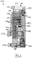
- Fig. 1
- eine perspektivische Ansicht einer Turbomolekularpumpe,
- Fig. 2
- eine Ansicht der Unterseite der Turbomolekularpumpe von
Fig. 1 , - Fig. 3
- einen Querschnitt der Turbomolekularpumpe längs der in
Fig. 2 gezeigten Schnittlinie A-A, - Fig. 4
- eine Querschnittsansicht der Turbomolekularpumpe längs der in
Fig. 2 gezeigten Schnittlinie B-B, - Fig. 5
- eine Querschnittsansicht der Turbomolekularpumpe längs der in
Fig. 2 gezeigten Schnittlinie C-C, - Fig. 6
- Einbaumöglichkeiten der Abschirmung, und
- Fig. 7
- eine Aufbaumöglichkeit der Abschirmung.
- In den
Fig. 1 bis 5 wird ein möglicher Aufbau einer Vakuumpumpe 111 beschrieben. Die Beschreibung erfolgt hier ohne die Darstellung der Abschirmung. Die Einbaumöglichkeiten der Abschirmung sind inFig. 6 in Kombination gezeigt. Diese Möglichkeiten sind als mit den Merkmalen derFig. 1 bis 5 kombinierbar zu verstehen.Fig. 7 zeigt den möglichen Aufbau einer Abschirmung, was wiederum als mit den Merkmalen derFig. 6 und derFig. 1 bis 5 kombinierbar zu verstehen ist. - Die in
Fig. 1 gezeigte Turbomolekularpumpe 111 umfasst einen von einem Einlassflansch 113 umgebenen Pumpeneinlass 115, an welchen in an sich bekannter Weise ein nicht dargestellter Rezipient angeschlossen werden kann. Das Gas aus dem Rezipienten kann über den Pumpeneinlass 115 aus dem Rezipienten gesaugt und durch die Pumpe hindurch zu einem Pumpenauslass 117 gefördert werden, an den eine Vorvakuumpumpe, wie etwa eine Drehschieberpumpe, angeschlossen sein kann. - Der Einlassflansch 113 bildet bei der Ausrichtung der Vakuumpumpe gemäß
Fig. 1 das obere Ende des Gehäuses 119 der Vakuumpumpe 111. Das Gehäuse 119 umfasst ein Unterteil 121, an welchem seitlich ein Elektronikgehäuse 123 angeordnet ist. In dem Elektronikgehäuse 123 sind elektrische und/oder elektronische Komponenten der Vakuumpumpe 111 untergebracht, z.B. zum Betreiben eines in der Vakuumpumpe angeordneten Elektromotors 125. Am Elektronikgehäuse 123 sind mehrere Anschlüsse 127 für Zubehör vorgesehen. Außerdem sind eine Datenschnittstelle 129, z.B. gemäß dem RS485-Standard, und ein Stromversorgungsanschluss 131 am Elektronikgehäuse 123 angeordnet. - Am Gehäuse 119 der Turbomolekularpumpe 111 ist ein Fluteinlass 133, insbesondere in Form eines Flutventils, vorgesehen, über den die Vakuumpumpe 111 geflutet werden kann. Im Bereich des Unterteils 121 ist ferner noch ein Sperrgasanschluss 135, der auch als Spülgasanschluss bezeichnet wird, angeordnet, über welchen Spülgas zum Schutz des Elektromotors 125 (siehe z.B.
Fig. 3 ) vor dem von der Pumpe geförderten Gas in den Motorraum 137, in welchem der Elektromotor 125 in der Vakuumpumpe 111 untergebracht ist, gebracht werden kann. Im Unterteil 121 sind ferner noch zwei Kühlmittelanschlüsse 139 angeordnet, wobei einer der Kühlmittelanschlüsse als Einlass und der andere Kühlmittelanschluss als Auslass für Kühlmittel vorgesehen ist, das zu Kühlzwecken in die Vakuumpumpe geleitet werden kann. - Die untere Seite 141 der Vakuumpumpe kann als Standfläche dienen, sodass die Vakuumpumpe 111 auf der Unterseite 141 stehend betrieben werden kann. Die Vakuumpumpe 111 kann aber auch über den Einlassflansch 113 an einem Rezipienten befestigt werden und somit gewissermaßen hängend betrieben werden. Außerdem kann die Vakuumpumpe 111 so gestaltet sein, dass sie auch in Betrieb genommen werden kann, wenn sie auf andere Weise ausgerichtet ist als in
Fig. 1 gezeigt ist. Es lassen sich auch Ausführungsformen der Vakuumpumpe realisieren, bei der die Unterseite 141 nicht nach unten, sondern zur Seite gewandt oder nach oben gerichtet angeordnet werden kann. - An der Unterseite 141, die in
Fig. 2 dargestellt ist, sind noch diverse Schrauben 143 angeordnet, mittels denen hier nicht weiter spezifizierte Bauteile der Vakuumpumpe aneinander befestigt sind. Beispielsweise ist ein Lagerdeckel 145 an der Unterseite 141 befestigt. - An der Unterseite 141 sind außerdem Befestigungsbohrungen 147 angeordnet, über welche die Pumpe 111 beispielsweise an einer Auflagefläche befestigt werden kann.
- In den
Figuren 2 bis 5 ist eine Kühlmittelleitung 148 dargestellt, in welcher das über die Kühlmittelanschlüsse 139 ein- und ausgeleitete Kühlmittel zirkulieren kann. - Wie die Schnittdarstellungen der
Figuren 3 bis 5 zeigen, umfasst die Vakuumpumpe mehrere Prozessgaspumpstufen zur Förderung des an dem Pumpeneinlass 115 anstehenden Prozessgases zu dem Pumpenauslass 117. - In dem Gehäuse 119 ist ein Rotor (auch als "Pumpenrotor" angesprochen) 149 angeordnet, der eine um eine Rotationsachse 151 drehbare Rotorwelle 153 aufweist.
- Die Turbomolekularpumpe 111 umfasst mehrere pumpwirksam miteinander in Serie geschaltete turbomolekulare Pumpstufen mit mehreren an der Rotorwelle 153 befestigten radialen Rotorscheiben 155 und zwischen den Rotorscheiben 155 angeordneten und in dem Gehäuse 119 festgelegten Statorscheiben 157 (zusammen auch als "Pumpenstator 157" angesprochen). Dabei bilden eine Rotorscheibe 155 und eine benachbarte Statorscheibe 157 jeweils eine turbomolekulare Pumpstufe. Die Statorscheiben 157 sind durch Abstandsringe 159 in einem gewünschten axialen Abstand zueinander gehalten.
- Die Vakuumpumpe umfasst außerdem in radialer Richtung ineinander angeordnete und pumpwirksam miteinander in Serie geschaltete Holweck-Pumpstufen. Der Rotor der Holweck-Pumpstufen umfasst eine an der Rotorwelle 153 angeordnete Rotornabe 161 und zwei an der Rotornabe 161 befestigte und von dieser getragene zylindermantelförmige Holweck-Rotorhülsen 163, 165, die koaxial zur Rotationsachse 151 orientiert und in radialer Richtung ineinander geschachtelt sind. Ferner sind zwei zylindermantelförmige Holweck-Statorhülsen 167, 169 vorgesehen, die ebenfalls koaxial zu der Rotationsachse 151 orientiert und in radialer Richtung gesehen ineinander geschachtelt sind.
- Die pumpaktiven Oberflächen der Holweck-Pumpstufen sind durch die Mantelflächen, also durch die radialen Innen- und/oder Außenflächen, der Holweck-Rotorhülsen 163, 165 und der Holweck-Statorhülsen 167, 169 gebildet. Die radiale Innenfläche der äußeren Holweck-Statorhülse 167 liegt der radialen Außenfläche der äußeren Holweck-Rotorhülse 163 unter Ausbildung eines radialen Holweck-Spalts 171 gegenüber und bildet mit dieser die der Turbomolekularpumpen nachfolgende erste Holweck-Pumpstufe. Die radiale Innenfläche der äußeren Holweck-Rotorhülse 163 steht der radialen Außenfläche der inneren Holweck-Statorhülse 169 unter Ausbildung eines radialen Holweck-Spalts 173 gegenüber und bildet mit dieser eine zweite Holweck-Pumpstufe. Die radiale Innenfläche der inneren Holweck-Statorhülse 169 liegt der radialen Außenfläche der inneren Holweck-Rotorhülse 165 unter Ausbildung eines radialen Holweck-Spalts 175 gegenüber und bildet mit dieser die dritte Holweck-Pumpstufe.
- Am unteren Ende der Holweck-Rotorhülse 163 kann ein radial verlaufender Kanal vorgesehen sein, über den der radial außenliegende Holweck-Spalt 171 mit dem mittleren Holweck-Spalt 173 verbunden ist. Außerdem kann am oberen Ende der inneren Holweck-Statorhülse 169 ein radial verlaufender Kanal vorgesehen sein, über den der mittlere Holweck-Spalt 173 mit dem radial innenliegenden Holweck-Spalt 175 verbunden ist. Dadurch werden die ineinander geschachtelten Holweck-Pumpstufen in Serie miteinander geschaltet. Am unteren Ende der radial innenliegenden Holweck-Rotorhülse 165 kann ferner ein Verbindungskanal 179 zum Auslass 117 vorgesehen sein.
- Die vorstehend genannten pumpaktiven Oberflächen der Holweck-Statorhülsen 163, 165 weisen jeweils mehrere spiralförmig um die Rotationsachse 151 herum in axialer Richtung verlaufende Holweck-Nuten auf, während die gegenüberliegenden Mantelflächen der Holweck-Rotorhülsen 163, 165 glatt ausgebildet sind und das Gas zum Betrieb der Vakuumpumpe 111 in den Holweck-Nuten vorantreiben.
- Zur drehbaren Lagerung der Rotorwelle 153 sind ein Wälzlager 181 im Bereich des Pumpenauslasses 117 und ein Permanentmagnetlager 183 im Bereich des Pumpeneinlasses 115 vorgesehen.
- Im Bereich des Wälzlagers 181 ist an der Rotorwelle 153 eine konische Spritzmutter 185 mit einem zu dem Wälzlager 181 hin zunehmenden Außendurchmesser vorgesehen. Die Spritzmutter 185 steht mit mindestens einem Abstreifer eines Betriebsmittelspeichers in gleitendem Kontakt. Der Betriebsmittelspeicher umfasst mehrere aufeinander gestapelte saugfähige Scheiben 187, die mit einem Betriebsmittel für das Wälzlager 181, z.B. mit einem Schmiermittel, getränkt sind.
- Im Betrieb der Vakuumpumpe 111 wird das Betriebsmittel durch kapillare Wirkung von dem Betriebsmittelspeicher über den Abstreifer auf die rotierende Spritzmutter 185 übertragen und in Folge der Zentrifugalkraft entlang der Spritzmutter 185 in Richtung des größer werdenden Außendurchmessers der Spritzmutter 185 zu dem Wälzlager 181 hin gefördert, wo es z.B. eine schmierende Funktion erfüllt. Das Wälzlager 181 und der Betriebsmittelspeicher sind durch einen wannenförmigen Einsatz 189 und den Lagerdeckel 145 in der Vakuumpumpe eingefasst.
- Das Permanentmagnetlager 183 kann eine rotorseitige Lagerhälfte 191 und eine statorseitige Lagerhälfte 193 umfassen, welche jeweils einen Ringstapel aus mehreren in axialer Richtung aufeinander gestapelten permanentmagnetischen Ringen 195, 197 umfassen. Die Ringmagnete 195, 197 liegen einander unter Ausbildung eines radialen Lagerspalts 199 gegenüber, wobei die rotorseitigen Ringmagnete 195 radial außen und die statorseitigen Ringmagnete 197 radial innen angeordnet sind. Das in dem Lagerspalt 199 vorhandene magnetische Feld ruft magnetische Abstoßungskräfte zwischen den Ringmagneten 195, 197 hervor, welche eine radiale Lagerung der Rotorwelle 153 bewirken. Die rotorseitigen Ringmagnete 195 sind von einem Trägerabschnitt 201 der Rotorwelle 153 getragen, der umlaufend hülsenförmig ausgebildet sein kann und die Ringmagnete 195 radial außen hält und ggf. umgibt. Die statorseitigen Ringmagnete 197 sind von einem statorseitigen Trägerabschnitt 203 getragen, welcher sich durch die Ringmagnete 197 hindurch erstreckt und an radialen Streben 205 des Gehäuses 119 aufgehängt ist. Parallel zu der Rotationsachse 151 sind die rotorseitigen Ringmagnete 195 durch ein mit dem Trägerabschnitt 203 gekoppeltes Deckelelement 207 festgelegt. Die statorseitigen Ringmagnete 197 sind parallel zu der Rotationsachse 151 in der einen Richtung durch einen mit dem Trägerabschnitt 203 verbundenen Befestigungsring 209 sowie einen mit dem Trägerabschnitt 203 verbundenen Befestigungsring 211 festgelegt. Zwischen dem Befestigungsring 211 und den Ringmagneten 197 kann außerdem eine Tellerfeder 213 vorgesehen sein.
- Innerhalb des Magnetlagers ist ein Not- bzw. Fanglager 215 vorgesehen, welches im normalen Betrieb der Vakuumpumpe 111 ohne Berührung leer läuft und erst bei einer übermäßigen radialen Auslenkung des Rotors 149 relativ zu dem Stator in Eingriff gelangt, um einen radialen Anschlag für den Rotor 149 zu bilden, da eine Kollision der rotorseitigen Strukturen mit den statorseitigen Strukturen verhindert wird. Das Fanglager 215 ist als ungeschmiertes Wälzlager ausgebildet und bildet mit dem Rotor 149 und/oder dem Stator einen radialen Spalt, welcher bewirkt, dass das Fanglager 215 im normalen Pumpbetrieb außer Eingriff ist. Die radiale Auslenkung, bei der das Fanglager 215 in Eingriff gelangt, ist groß genug bemessen, sodass das Fanglager 215 im normalen Betrieb der Vakuumpumpe nicht in Eingriff gelangt, und gleichzeitig klein genug, sodass eine Kollision der rotorseitigen Strukturen mit den statorseitigen Strukturen unter allen Umständen verhindert wird.
- Die Vakuumpumpe 111 umfasst den Elektromotor 125 zum drehenden Antreiben des Rotors 149. Der Anker des Elektromotors 125 ist durch den Rotor 149 gebildet, dessen Rotorwelle 153 sich durch den Motorstator 217 hindurch erstreckt. Auf den sich durch den Motorstator 217 hindurch erstreckenden Abschnitt der Rotorwelle 153 kann radial außenseitig oder eingebettet eine Permanentmagnetanordnung angeordnet sein. Zwischen dem Motorstator 217 und dem sich durch den Motorstator 217 hindurch erstreckenden Abschnitt des Rotors 149 ist ein Zwischenraum 219 angeordnet, welcher einen radialen Motorspalt umfasst, über den sich der Motorstator 217 und die Permanentmagnetanordnung zur Übertragung des Antriebsmoments magnetisch beeinflussen können.
- Der Motorstator 217 ist in dem Gehäuse innerhalb des für den Elektromotor 125 vorgesehenen Motorraums 137 festgelegt. Über den Sperrgasanschluss 135 kann ein Sperrgas, das auch als Spülgas bezeichnet wird, und bei dem es sich beispielsweise um Luft oder um Stickstoff handeln kann, in den Motorraum 137 gelangen. Über das Sperrgas kann der Elektromotor 125 vor Prozessgas, z.B. vor korrosiv wirkenden Anteilen des Prozessgases, geschützt werden. Der Motorraum 137 kann auch über den Pumpenauslass 117 evakuiert werden, d.h. im Motorraum 137 herrscht zumindest annäherungsweise der von der am Pumpenauslass 117 angeschlossenen Vorvakuumpumpe bewirkte Vakuumdruck.
- Zwischen der Rotornabe 161 und einer den Motorraum 137 begrenzenden Wandung 221 kann außerdem eine sog. und an sich bekannte Labyrinthdichtung 223 vorgesehen sein, insbesondere um eine bessere Abdichtung des Motorraums 217 gegenüber den radial außerhalb liegenden Holweck-Pumpstufen zu erreichen.
-
Fig. 6 zeigt schematisiert und vereinfacht, was in ähnlicher Weise inFig. 3 gezeigt wurde, jedoch mit Einbaumöglichkeiten der genannten Abschirmung. Die Abschirmungen derFig. 6 sind mit den Bezugsziffern 601 bis 605 bezeichnet. Wie schon vorher erwähnt, kann eine einzelne dieser Abschirmungen vorgesehen sein, oder es können mehrere der Abschirmungen kombiniert miteinander vorgesehen sein. - Allgemein kann die Abschirmung als selbsttragendes Bauteil oder als nicht selbsttragendes Bauteil oder als Beschichtung ausgebildet sein. Es kann sich um ein geeignet geformtes flächensteifes Material handeln, bspw. ein Blech, oder um ein folienartiges Material oder um eine an den dargestellten Orten durch geeignete Verfahren aufgebrachte Beschichtung. Bauteil oder Beschichtung sind mit dem gewünschten Material in der gewünschten Dicke gefertigt.
- Mit 601 ist eine Abschirmung bezeichnet, die am Innenumfang des Gehäuses 119 anliegt. Sie kann eine selbsttragende stabile Hülse sein oder kann eine weniger stabile Struktur sein, die auf die Innenoberfläche des Gehäuses 119 aufgeklebt oder sonstwie geeignet befestigt ist. Sie kann, wie in
Fig. 6 angedeutet, in axialer Richtung das Pumpeninnere weitgehend vollständig überdecken. Sie kann aber, wenn beispielsweise nur das Magnetlager abgeschirmt werden soll, auch (in axialer Richtung betrachtet) nur im Bereich des Magnetlagers vorgesehen sein. - Der Bedeckungsgrad des Magnetlagers mit der Abschirmung in axialer Richtung betrachtet kann eine Untergrenze von 80% seiner axialen Länge oder von 90% oder von 100% oder von 110% haben und/oder kann eine Obergrenze von 90% oder 95% oder 100% oder 110% oder 120% oder 150% haben. In Umfangsrichtung läuft die Abschirmung 601 vorzugsweise vollständig um den Umfang um.
- Die Abschirmung 601 kann eine stabile Hülse sein. Sie kann einen zylindrischen Teil aufweisen, der in
Fig. 6 von unten nach oben verlaufend mit Bezugsziffer 601a bezeichnet ist. Sie kann weiterhin einen am einen axialen Ende des zylindrischen Teils 601a angesetzten radial verlaufenden Teil (Kragen) 601b aufweisen, der sich vom zylindrischen Teil 601a aus radial einwärts erstreckt und etwa noch den Flansch 113 der Pumpe innen überdeckt. Die radiale Erstreckung einwärts des Kragens 601b kann so weit sein, dass die Öffnung 115 der Pumpe im Wesentlichen unbedeckt bleibt. Es ist aber auch möglich, den Kragen 601b gitterartig weiter nach radial innen zu ziehen, so dass einerseits ein Splitterschutz entsteht und andererseits auch in axialer Richtung eine magnetische Abschirmung gegeben ist. In diesem Fall kann der Kragen 601b (nicht gezeigt) bis über die radial innere Grenze der Öffnung 115 hinaus nach innen laufen. - Die
Fig. 6 zeigt schematisch die Pumpstufen von sich radial erstreckenden Stator- und Rotorelementen, die von der Abschirmung 601 überdeckt sind. Sie kann aber auch oder stattdessen noch so weit gezogen sein, dass sie auch eine Holweck-Statorhülse 167, 169 radial außen mit abdeckt. - Wenn eine Holweck-Hülse 167, 169 vorgesehen ist, kann diese aber auch selbst aus magnetfeldschirmendem Material hergestellt sein und dan in geeigneter Weise verbaut werden. Vorzugsweise wird dies dann mit der radial äußersten Holweck-Hülse gemacht, die in der Regel eine Statorhülse ist.
-
Fig. 6 zeigt als Option auch, dass Abstandsringe 159, 604 als Abschirmung gebaut werden können, indem sie aus einem geeigneten schirmenden Material hergestellt werden. In axialer Richtung betrachtet nehmen die Abstandsringe 159, 604 einen merklichen Anteil der Länge ein, in der Regel über 70% oder über 80%, so dass durch entsprechende Ausbildung dieser Ringe 70 bis 80% der Länge magnetisch abgeschirmt werden können. Da die Ringe auch eine gewisse Dicke haben, kann entsprechend der Dicke die Abschirmung gewünscht gestaltet werden. - Die bisher beschriebenen Abschirmungen 601 und 604 liegen weitgehend außerhalb der Stator- und Rotorkomponenten. Es ist aber auch möglich, die Abschirmung radial betrachtet innerhalb von Rotorkomponenten vorzusehen. In
Fig. 6 ist dies mit den Bezugsziffern 602, 603 und 605 gezeigt. - Bezugsziffer 201, 605 zeigt die Halterung für die radial außenliegenden Magnetringe 195 des Magnetlagers. In der Regel sind dies die Magnetringe der rotorseitigen Lagerhälfte, während die Ringe 197 der statorseitigen Lagerhälfte auf einem Zapfen radial innen sitzen. Die Verhältnisse können bei anderen Konstruktionen aber auch anders herum sein (also dass die statorseitige Lagerhälfte radial außen liegt).
- In jedem Fall sind die radial außenliegenden Magnetringe (195 in
Fig. 6 ) durch eine geeignete Haltestruktur zu halten, die ihrerseits wieder weiter radial außen liegt. In der Regel ist sie hülsenförmig oder becherförmig aufgebaut und bildet einen Trägerabschnitt 201, der dann Teil der Rotorwelle 153 bilden kann. Der Trägerabschnitt 201, 605 selbst kann aus einem schirmenden Material gefertigt sein und dann in geeigneter Weise mit der Welle 153 bzw. einem Statorteil verbunden sein, etwa durch Verschrauben oder ähnliches. Der Trägerabschnitt 201, 605 läuft vorzugsweise lückenlos um den Umfang der Lagermagnete um und überdeckt in axialer Richtung betrachtet die radial außenliegenden Magnetringe 195 sowie auch die radial innenliegenden Magnetringe 197 vorzugsweise vollständig. Am Boden des Bechers können auch Komponenten, die sich radial einwärts zur Achse 151 der Pumpe hin erstrecken, noch mit dem schirmenden Material ausgeführt sein. Nicht dargestellt ist inFig. 6 eine Unterbrechung des Aufbaus der Welle 153 dahingehend, dass der Trägerabschnitt 201 letztlich ein anderes Bauteil sein kann als der Hauptteil der Welle 153 und mit diesem geeignet verbunden ist. - Sinngemäß gleiche Gedanken gelten, wenn der Rotorteil des Lagers radial innen liegt. Dann liegen die Statormagneten radial außen und werden von dem dazu radial außen liegenden Trägerabschnitt 201 gehalten, der mit statischen Teilen der Pumpe verbunden ist.
- Weitere Ausführungsformen des Einbaus der Abschirmung zeigen optional als Kombination die Bezugsziffern 602 und 603. Radial innen und/oder radial außen am (womöglich konventionell ausgebildeten) Trägerabschnitt 201 liegen Abschirmungen. Zur Überdeckung der abgeschirmten Komponenten, insbesondere der Magneten des Magnetlagers gilt sinngemäß das Gleiche wie zur Überdeckung durch die Hülse 601 gesagt wurde.
- Die innen und/oder außen am Trägerabschnitt 201 vorgesehenen Abschirmungen 603, 602 können selbst wieder selbsttragende Bauteile sein, die selbstständig hergestellt und gehandhabt werden können, oder es kann sich um nicht selbsttragende Teile handeln ähnlich einer Folie, wie dies schon zu Bezugszeichen 601 erläutert wurde.
- Das Vorsehen der Abschirmung unmittelbar im Bereich des Magnetlagers (also Bezugsziffern 602, 603, 605) hat den Vorteil, dass wegen des kleinen Radius die schirmenden Strukturen umlaufend relativ klein sind, so dass dementsprechend auch Materialkosten für schirmende Materialien relativ gering bleiben. Darüber hinaus ist dann auch das Pumpeninnere gegenüber Auswirkungen der Magnetfelder des Magnetlagers abgeschirmt.
- Die Abschirmung weist ein Material auf, das Magnetfelder in gewünschter Weise dämpft. Das Material hat vorzugsweise eine vergleichsweise hohe relative magnetische Permeabilität und hat vorzugsweise hinreichend elektrische Leitfähigkeit. Die relative magnetische Permeabilität µr kann größer 300 oder größer 1.000 oder größer 10.000 oder größer 30.000 oder sogar größer als 100.000 sein. Die elektrische Leitfähigkeit des schirmenden Materials ist mindestens 1% oder mindestens 10% oder mindestens 20% oder mindestens 50% die von Kupfer.
- Wenn mehrere Abschirmungen (601 und/oder 602 und/oder 603 und/oder 604 und/oder 605) vorgesehen sind, können sie teils als selbsttragendes oder nicht selbsttragendes Bauteil und teils als Beschichtung ausgebildet sein. Sie können aber auch nur als selbsttragendes oder nicht selbsttragendes Bauteil oder nur als Beschichtung ausgebildet sein.
- Das schirmende Material ist vorzugsweise ein metallisches Material oder weist wenigstens metallisches Material auf. Das metallische Material kann eine Legierung sein. Die Legierung kann überwiegend Nickel aufweisen und kann beispielsweise Mu-Metall sein, oder sie weist vergleichsweise viel Kobalt auf und weist vorzugsweise Vitrovac auf.
- Implizit wurde bisher ein intern homogener Aufbau der Abschirmung 601 - 605 beschrieben. Tatsächlich kann dies auch der Fall sein, indem die Abschirmung homogen aus einem geeigneten Material gefertigt ist. Genauso gut ist es aber möglich, die Abschirmung als Kompositaufbau vorzusehen und insbesondere als ein Bauteil mit mehreren Lagen/Schichten auszubilden.
Fig. 7 zeigt dies schematisch im Querschnitt. Gezeigt sind zwei Lagen, die eine Trägerlage 701 und eine Abschirmlage 702 aufweisen können. Die Trägerlage kann mechanisch stabil und reißfest und biegefest sein. Sie kann zu einer vorgeformten selbsttragenden Struktur formbar sein, um etwa Hülsen entsprechend 601, 602 oder 603 zu bilden. - Die Trägerlage kann aus einem metallischen Material bestehen, insbesondere einem Blech, das vergleichsweise dünn sein kann, beispielsweise dünner als 1 mm oder dünner als 500 µm. Vorzugsweise weist die Trägerlage eine Dicke von weniger als 250 µm auf, beispielsweise konkret eine Dicke von ca. 200 µm. Es kann sich beispielsweise um Stahlblech handeln oder ein sonst geeignetes Blech. Die Trägerlage kann metallisch leitend sein.
- Die Abschirmung 601 bis 605 bzw. die Abschirmschicht 702 kann eine Dicke von unter 2 mm oder unter 1 mm aufweisen. Sie kann auch unter 500 µm oder unter 200 µm oder unter 100 µm oder unter 50 µm Dicke liegen.
- Auf der Trägerlage ist eine Abschirmlage 702 ausgebildet. Die Abschirmlage kann, muss aber nicht selbsttragend sein. Sie kann auch für sich alleine instabil oder nur gering biegebeständig sein und wird dann mechanisch im Wesentlichen von der Trägerlage 701 gehalten. Das Aufbringen der Abschirmlage 702 auf der Trägerlage 701 kann durch geeignete Prozessschritte erfolgen. Sie kann erfolgen, nachdem die Trägerlage 701 in die gewünschte Form gebracht wurde.
- Es ist aber möglich, die Trägerlage 701 nicht selbsttragend auszubilden. Sie weist dann noch eine gewisse Reißfestigkeit auf, um ein womöglich sprödes Material der Abschirmlage beieinander halten zu können. Sie kann bspw. eine Trägerfolie eines darauf ausgebildeten abschirmenden Materials sein.
- Das Befestigen der Abschirmlage 702 auf der Trägerlage 701 kann beispielsweise durch Verkleben erfolgen. Der Klebstoff kann als eigene (in
Fig. 7 nicht gezeigte) Lage/Schicht erkennbar sein. Auch die Anbringung der Abschirmung gemäßFig. 7 in der Pumpe kann durch Verkleben erfolgen, so dass an einer der freien Oberflächen, z. B. an der freien Oberfläche der Trägerlage 701, eine Klebeschicht vorgesehen sein kann. Sie kann punktuell oder flächendeckend vorgesehen sein. - Die
Fig. 6 zeigt die vorwiegend in radialer Richtung wirkenden Abschirmungen 601 bis 605. Es kann darüber hinaus eine in axialer Richtung nach oben wirkende Abschirmung der Öffnung 115 vorgesehen sein. Sie kann gitterförmig ausgebildet sein, um den Durchtritt des durch die Pumpe abzusaugenden Gases zu gestatten. Die Abschirmung kann dann gitterförmig über der Öffnung 115 liegen. Wie schon gesagt, kann sie als Baueinheit mit beispielsweise der hülsenförmigen Abschirmung 601 ausgebildet sein. Sie kann aber auch separat anbringbar und montierbar sein oder kann in Baueinheit mit einer der Abschirmungen 602, 603 oder 605 vorgesehen sein. Sie kann auch als Baueinheit mit dem obersten Abstandshalter 159, 604 ausgebildet sein. - Der zweilagige Aufbau der
Fig. 7 bzw. allgemein ein mehrlagiger Aufbau kann in allen Abschirmungen 601 bis 605 gewählt sein. Die Abstandsringe 604 können mehrere Lagen in Form mehrerer in radialer Richtung verschachtelter Ringe aufweisen. Die Abschirmlage 701 kann dann radial innerhalb oder radial außerhalb der Trägerlage 702 liegen. - Merkmale, die in dieser Beschreibung und in den Patentansprüchen dargestellt sind, sollen auch dann als miteinander kombinierbar verstanden werden, wenn die Kombination nicht explizit angegeben ist, soweit die Kombination technisch möglich ist. Merkmale aus gewissen Figuren, Ausführungsformen, Ansprüchen oder Kontexten sollen auch aus diesen Ansprüchen, Kontexten, Ausführungsformen bzw. Figuren herauslösbar verstanden werden, soweit dies technisch möglich ist, und sollen mit anderen Ansprüchen, Figuren, Kontexten oder Ausführungsformen kombinierbar verstanden werden.
-
- 111
- Vakuumpumpe
- 113
- Einlassflansch
- 115
- Pumpeneinlass
- 117
- Pumpenauslass
- 119
- Gehäuse
- 121
- Unterteil
- 123
- Elektronikgehäuse
- 125
- Elektromotor
- 127
- Anschlüsse
- 129
- Datenschnittstelle
- 131
- Stromversorgungsanschluss
- 133
- Fluteinlass
- 135
- Sperrgasanschluss
- 137
- Motorraum
- 139
- Kühlmittelanschlüsse
- 141
- untere Seite
- 143
- Schrauben
- 145
- Lagerdeckel
- 147
- Befestigungsbohrungen
- 148
- Kühlmittelleitung
- 149
- Pumpenrotor
- 151
- Rotorachse
- 153
- Rotorwelle
- 155
- Rotorscheibe
- 157
- Statorscheibe
- 159
- Abstandsring
- 161
- Rotornabe
- 163, 165
- Holweck-Rotorhülse
- 167, 169
- Holweck-Statorhülse
- 171
- Spalt
- 173, 175
- Holweckspalt
- 179
- Verbindungskanal
- 181
- Wälzlager
- 183
- Permanentmagnetlager
- 185
- Spritzmutter
- 187
- Scheiben
- 191
- rotorseitige Lagerhälfte
- 193
- statorseitige Lagerhälfte
- 195, 197
- Ringmagnete
- 203
- Trägerabschnitt
- 207
- Deckelelement
- 211
- Befestigungsring
- 213
- Tellerfeder
- 215
- Fanglager
- 217
- Motorstator
- 219
- Zwischenraum
- 221
- Wandung
- 223
- Labyrinthdichtung
- 601 - 605
- Abschirmung
- 701
- Trägerlage
- 702
- Abschirmungslage
Claims (15)
- Vakuumpumpe mit
einem Gehäuse (119),
einem Pumpenrotor (149, 163, 165) mit einer Rotorwelle (153) im Gehäuse (119),
einem Pumpenstator (157, 167, 169) im Gehäuse (119), der relativ zum Pumpenrotor (149) pumpwirksam angeordnet ist,
einem Pumpeneinlass (115) im Bereich eines Endes der Rotorwelle (153), einem Magnetlager, insbesondere Permanentmagnetlager (183) für die Rotorwelle (153) im Bereich des Pumpeneinlasses (115),
einer Abschirmung (601 - 605) von Magnetfeldern,
dadurch gekennzeichnet, dass die Abschirmung (601 - 605) im Inneren des Gehäuses (119) vorgesehen ist und in axialer Richtung und/oder in Umfangsrichtung betrachtet das Magnetlager (183) ganz oder teilweise überdeckt und/oder in axialer Richtung und/oder in Umfangsrichtung betrachtet den Pumpenrotor (149) und den Pumpenstator (157) ganz oder teilweise überdeckt. - Pumpe nach Anspruch 1,
dadurch gekennzeichnet, dass die Abschirmung (602, 603) in radialer Richtung betrachtet innerhalb von Komponenten des Pumpenstators (157) liegt. - Pumpe nach Anspruch 1 oder 2,
dadurch gekennzeichnet, dass die Abschirmung (601) in radialer Richtung betrachtet außerhalb des Pumpenrotors (149) und außerhalb des Pumpenstators (157) angebracht ist und an der Innenwand des Gehäuses (119) anliegen kann. - Pumpe nach zumindest einem der vorstehenden Ansprüche,
dadurch gekennzeichnet, dass die Abschirmung (601 - 603) eine Hülse mit einem zylindrischen Hülsenbereich (601a) aufweist und einen am Hülsenbereich (601a) angesetzten Kragenbereich (601b) aufweisen kann, der sich radial einwärts erstreckt und der am pumpeneinlassseitigen Ende der Hülse liegt. - Pumpe nach zumindest einem der vorstehenden Ansprüche,
dadurch gekennzeichnet, dass der Pumpenstator (157) in axialer Richtung gestapelt Statorscheiben (157) und Abstandsringe (159, 604) aufweist, wobei die Abstandsringe (159, 604) ein die Abschirmung bildendes Material aufweisen. - Pumpe nach zumindest einem der vorstehenden Ansprüche,
dadurch gekennzeichnet, dass das Permanentmagnetlager (183) eine mit dem Pumpenstator (157) verbundenen statorseitige Lagerhälfte (193) mit Statormagneten (197) und eine mit dem Pumpenrotor (149) verbundenen rotorseitige Lagerhälfte (191) mit Rotormagneten (195) aufweist, die radial außerhalb der statorseitigen Lagerhälfte (193) liegt, wobei die Rotormagneten (195) von einer radial außen liegenden hülsenförmigen Trägerabschnitt (201, 605) gehalten werden, der aus einem die Abschirmung bildenden Material hoher relativer magnetischer Permeabilität gefertigt ist. - Pumpe nach zumindest einem der vorstehenden Ansprüche,
dadurch gekennzeichnet, dass das Permanentmagnetlager (183) eine mit dem Pumpenstator (157) verbundene statorseitige Lagerhälfte (193) mit Statormagneten (197) und eine mit dem Pumpenrotor (149) verbundene rotorseitige Lagerhälfte (191) mit Rotormagneten (195) aufweist, die radial außerhalb der statorseitigen Lagerhälfte (193) liegt, wobei die Rotormagneten (195) von einer radial außen liegenden hülsenförmigen Trägerabschnitt (201) gehalten werden, wobei die Abschirmung (602, 603) von einer an der Außenoberfläche und/oder der Innenoberfläche des Trägerabschnitts (201) anliegenden Hülse oder Folie aus einem die Abschirmung bildenden Material hoher relativer magnetischer Permeabilität gefertigt ist. - Pumpe nach zumindest einem der Ansprüche 1 bis 5,
dadurch gekennzeichnet, dass das Permanentmagnetlager eine mit dem Pumpenstator verbundene statorseitige Lagerhälfte mit Statormagneten und eine mit dem Pumpenrotor verbundene rotorseitige Lagerhälfte mit Rotormagneten aufweist, die radial innerhalb der statorseitigen Lagerhälfte liegt, wobei die Statormagneten von einer radial außen liegenden hülsenförmigen Trägerabschnitt gehalten werden, der aus einem die Abschirmung bildenden Material hoher relativer magnetischer Permeabilität gefertigt ist. - Pumpe nach zumindest einem der vorstehenden Ansprüche,
dadurch gekennzeichnet, dass sie eine Holweck-Statorhülse (167, 169) aufweist und die Abschirmung radial außerhalb derselben ausgebildet ist oder die Holweckhülse selbst aus einem magnetfeldschirmenden Material gefertigt ist. - Pumpe nach zumindest einem der vorstehenden Ansprüche,
dadurch gekennzeichnet, dass der Einlass die Öffnung des Pumpeneinlasses (115) ein Gitter aufweist, das ein magnetfeldschirmendes Material aufweist. - Pumpe nach zumindest einem der vorstehenden Ansprüche,
dadurch gekennzeichnet, dass die Abschirmung (601 - 605) eine Folie oder ein flächensteifes Material aufweist, die bzw. das mehrlagig mit einer Trägerlage (701) und einer Abschirmlage (702) ausgebildet ist und die eine vorab aufgebrachte Klebeschicht aufweisen kann. - Pumpe nach Anspruch 11,
dadurch gekennzeichnet, dass die Trägerlage (701) ferromagnetischen Stahl und/oder Kupfer und/oder Aluminium aufweist. - Pumpe nach Anspruch 11 oder 12,
dadurch gekennzeichnet, dass die Trägerlage (701) selbsttragend ist und die Abschirmungslage (702) auf die Trägerlage (701) aufgebracht ist und von ihr getragen wird. - Pumpe nach zumindest einem der vorstehenden Ansprüche,
dadurch gekennzeichnet, dass die Abschirmung (601 - 605) ein metallisches Material aufweist, das insbesondere eine Legierung mit überwiegend Nickel, insbesondere Mu-Metall und/oder Vitrovac® und/oder eine Legierung mit überwiegend Kobalt aufweisen kann und/oder das ein Material mit einer hohen relativen magnetischen Permeabilität (µr) aufweisen kann, die über 1.000 oder über 3.000 oder über 10.000 oder über 30.000 oder über 100.000 liegen kann. - Pumpe nach zumindest einem der vorstehenden Ansprüche,
dadurch gekennzeichnet, dass
die Abschirmung (601 - 605) ein elektrisch leitfähiges Material aufweist, dessen spezifische elektrische Leitfähigkeit mindestens 1% oder mindestens10% oder mindestens 20% oder mindestens 50% der Leitfähigkeit von Kupfer beträgt.
Priority Applications (1)
| Application Number | Priority Date | Filing Date | Title |
|---|---|---|---|
| EP18200472.1A EP3640481B1 (de) | 2018-10-15 | 2018-10-15 | Vakuumpumpe |
Applications Claiming Priority (1)
| Application Number | Priority Date | Filing Date | Title |
|---|---|---|---|
| EP18200472.1A EP3640481B1 (de) | 2018-10-15 | 2018-10-15 | Vakuumpumpe |
Publications (2)
| Publication Number | Publication Date |
|---|---|
| EP3640481A1 true EP3640481A1 (de) | 2020-04-22 |
| EP3640481B1 EP3640481B1 (de) | 2023-05-03 |
Family
ID=63862041
Family Applications (1)
| Application Number | Title | Priority Date | Filing Date |
|---|---|---|---|
| EP18200472.1A Active EP3640481B1 (de) | 2018-10-15 | 2018-10-15 | Vakuumpumpe |
Country Status (1)
| Country | Link |
|---|---|
| EP (1) | EP3640481B1 (de) |
Citations (8)
| Publication number | Priority date | Publication date | Assignee | Title |
|---|---|---|---|---|
| JPH01190991A (ja) * | 1988-01-26 | 1989-08-01 | Osaka Shinku Kiki Seisakusho:Kk | 真空ポンプ |
| US5679992A (en) * | 1995-10-11 | 1997-10-21 | Ebara Corporation | Bearing unit |
| US20010012488A1 (en) * | 1999-12-21 | 2001-08-09 | Yoshinobu Ohtachi | Vaccum pump |
| JP3119272U (ja) * | 2005-12-08 | 2006-02-16 | 株式会社島津製作所 | 分子ポンプ |
| EP1669608A2 (de) | 2004-11-24 | 2006-06-14 | Pfeiffer Vacuum GmbH | Vakuumpumpe |
| US20130129482A1 (en) * | 2010-08-06 | 2013-05-23 | Shimadzu Corporation | Vacuum pump |
| EP3034881A1 (de) | 2014-12-18 | 2016-06-22 | Pfeiffer Vacuum GmbH | Vakuumpumpe |
| EP3088746A1 (de) * | 2015-04-30 | 2016-11-02 | Pfeiffer Vacuum Gmbh | Vakuumpumpe |
-
2018
- 2018-10-15 EP EP18200472.1A patent/EP3640481B1/de active Active
Patent Citations (8)
| Publication number | Priority date | Publication date | Assignee | Title |
|---|---|---|---|---|
| JPH01190991A (ja) * | 1988-01-26 | 1989-08-01 | Osaka Shinku Kiki Seisakusho:Kk | 真空ポンプ |
| US5679992A (en) * | 1995-10-11 | 1997-10-21 | Ebara Corporation | Bearing unit |
| US20010012488A1 (en) * | 1999-12-21 | 2001-08-09 | Yoshinobu Ohtachi | Vaccum pump |
| EP1669608A2 (de) | 2004-11-24 | 2006-06-14 | Pfeiffer Vacuum GmbH | Vakuumpumpe |
| JP3119272U (ja) * | 2005-12-08 | 2006-02-16 | 株式会社島津製作所 | 分子ポンプ |
| US20130129482A1 (en) * | 2010-08-06 | 2013-05-23 | Shimadzu Corporation | Vacuum pump |
| EP3034881A1 (de) | 2014-12-18 | 2016-06-22 | Pfeiffer Vacuum GmbH | Vakuumpumpe |
| EP3088746A1 (de) * | 2015-04-30 | 2016-11-02 | Pfeiffer Vacuum Gmbh | Vakuumpumpe |
Also Published As
| Publication number | Publication date |
|---|---|
| EP3640481B1 (de) | 2023-05-03 |
Similar Documents
| Publication | Publication Date | Title |
|---|---|---|
| EP2807732B1 (de) | Elektrische maschine mit einem rotor zur kühlung der elektrischen maschine | |
| EP2829734B1 (de) | Vakuumpumpe | |
| EP3657021B1 (de) | Vakuumpumpe | |
| EP1767786A1 (de) | Tauchpumpenaggregat | |
| EP1768233A1 (de) | Spaltrohr | |
| EP3447299B1 (de) | Einstellring | |
| EP3693610B1 (de) | Molekularvakuumpumpe | |
| EP3318763B1 (de) | Vakuumdichtung, doppeldichtung, vakuumsystem und vakuumpumpe | |
| EP3135932B1 (de) | Vakuumpumpe und permanentmagnetlager | |
| EP1767787B2 (de) | Pumpenaggregat | |
| EP3640481B1 (de) | Vakuumpumpe | |
| EP2910791A1 (de) | Vakuumpumpe | |
| EP4325061B1 (de) | Turbomolekularvakuumpumpe | |
| EP4194700B1 (de) | Vakuumpumpe mit einer holweck-pumpstufe mit veränderlicher holweck-geometrie | |
| EP3327293B1 (de) | Vakuumpumpe mit mehreren einlässen | |
| EP3683447A1 (de) | Vakuumpumpe | |
| EP3196471B1 (de) | Vakuumpumpe | |
| EP3575610B1 (de) | Vakuumpumpe mit betriebsmittelspeicher | |
| EP3088746B1 (de) | Vakuumpumpe | |
| EP3339651B1 (de) | Vakuumpumpe | |
| EP3628883B1 (de) | Vakuumpumpe | |
| EP4151860B1 (de) | Vakuumpumpe | |
| EP4474654B1 (de) | Turbomolekularvakuumpumpe | |
| EP4155549B1 (de) | Vakuumpumpe mit verbessertem saugvermögen der holweck-pumpstufe | |
| EP3561307A1 (de) | Vakuumpumpe mit einem einlassflansch und einem lagerträger im einlass |
Legal Events
| Date | Code | Title | Description |
|---|---|---|---|
| PUAI | Public reference made under article 153(3) epc to a published international application that has entered the european phase |
Free format text: ORIGINAL CODE: 0009012 |
|
| STAA | Information on the status of an ep patent application or granted ep patent |
Free format text: STATUS: THE APPLICATION HAS BEEN PUBLISHED |
|
| AK | Designated contracting states |
Kind code of ref document: A1 Designated state(s): AL AT BE BG CH CY CZ DE DK EE ES FI FR GB GR HR HU IE IS IT LI LT LU LV MC MK MT NL NO PL PT RO RS SE SI SK SM TR |
|
| AX | Request for extension of the european patent |
Extension state: BA ME |
|
| STAA | Information on the status of an ep patent application or granted ep patent |
Free format text: STATUS: REQUEST FOR EXAMINATION WAS MADE |
|
| 17P | Request for examination filed |
Effective date: 20201014 |
|
| RBV | Designated contracting states (corrected) |
Designated state(s): AL AT BE BG CH CY CZ DE DK EE ES FI FR GB GR HR HU IE IS IT LI LT LU LV MC MK MT NL NO PL PT RO RS SE SI SK SM TR |
|
| STAA | Information on the status of an ep patent application or granted ep patent |
Free format text: STATUS: EXAMINATION IS IN PROGRESS |
|
| 17Q | First examination report despatched |
Effective date: 20211005 |
|
| GRAP | Despatch of communication of intention to grant a patent |
Free format text: ORIGINAL CODE: EPIDOSNIGR1 |
|
| STAA | Information on the status of an ep patent application or granted ep patent |
Free format text: STATUS: GRANT OF PATENT IS INTENDED |
|
| RIC1 | Information provided on ipc code assigned before grant |
Ipc: F04D 29/058 20060101ALI20230125BHEP Ipc: F04D 29/02 20060101ALI20230125BHEP Ipc: F04D 19/04 20060101AFI20230125BHEP |
|
| INTG | Intention to grant announced |
Effective date: 20230210 |
|
| GRAS | Grant fee paid |
Free format text: ORIGINAL CODE: EPIDOSNIGR3 |
|
| GRAA | (expected) grant |
Free format text: ORIGINAL CODE: 0009210 |
|
| STAA | Information on the status of an ep patent application or granted ep patent |
Free format text: STATUS: THE PATENT HAS BEEN GRANTED |
|
| AK | Designated contracting states |
Kind code of ref document: B1 Designated state(s): AL AT BE BG CH CY CZ DE DK EE ES FI FR GB GR HR HU IE IS IT LI LT LU LV MC MK MT NL NO PL PT RO RS SE SI SK SM TR |
|
| REG | Reference to a national code |
Ref country code: GB Ref legal event code: FG4D Free format text: NOT ENGLISH |
|
| REG | Reference to a national code |
Ref country code: AT Ref legal event code: REF Ref document number: 1564821 Country of ref document: AT Kind code of ref document: T Effective date: 20230515 Ref country code: CH Ref legal event code: EP |
|
| REG | Reference to a national code |
Ref country code: DE Ref legal event code: R096 Ref document number: 502018012069 Country of ref document: DE |
|
| REG | Reference to a national code |
Ref country code: IE Ref legal event code: FG4D Free format text: LANGUAGE OF EP DOCUMENT: GERMAN |
|
| REG | Reference to a national code |
Ref country code: LT Ref legal event code: MG9D |
|
| REG | Reference to a national code |
Ref country code: NL Ref legal event code: MP Effective date: 20230503 |
|
| PG25 | Lapsed in a contracting state [announced via postgrant information from national office to epo] |
Ref country code: SE Free format text: LAPSE BECAUSE OF FAILURE TO SUBMIT A TRANSLATION OF THE DESCRIPTION OR TO PAY THE FEE WITHIN THE PRESCRIBED TIME-LIMIT Effective date: 20230503 Ref country code: PT Free format text: LAPSE BECAUSE OF FAILURE TO SUBMIT A TRANSLATION OF THE DESCRIPTION OR TO PAY THE FEE WITHIN THE PRESCRIBED TIME-LIMIT Effective date: 20230904 Ref country code: NO Free format text: LAPSE BECAUSE OF FAILURE TO SUBMIT A TRANSLATION OF THE DESCRIPTION OR TO PAY THE FEE WITHIN THE PRESCRIBED TIME-LIMIT Effective date: 20230803 Ref country code: NL Free format text: LAPSE BECAUSE OF FAILURE TO SUBMIT A TRANSLATION OF THE DESCRIPTION OR TO PAY THE FEE WITHIN THE PRESCRIBED TIME-LIMIT Effective date: 20230503 Ref country code: ES Free format text: LAPSE BECAUSE OF FAILURE TO SUBMIT A TRANSLATION OF THE DESCRIPTION OR TO PAY THE FEE WITHIN THE PRESCRIBED TIME-LIMIT Effective date: 20230503 |
|
| PG25 | Lapsed in a contracting state [announced via postgrant information from national office to epo] |
Ref country code: RS Free format text: LAPSE BECAUSE OF FAILURE TO SUBMIT A TRANSLATION OF THE DESCRIPTION OR TO PAY THE FEE WITHIN THE PRESCRIBED TIME-LIMIT Effective date: 20230503 Ref country code: PL Free format text: LAPSE BECAUSE OF FAILURE TO SUBMIT A TRANSLATION OF THE DESCRIPTION OR TO PAY THE FEE WITHIN THE PRESCRIBED TIME-LIMIT Effective date: 20230503 Ref country code: LV Free format text: LAPSE BECAUSE OF FAILURE TO SUBMIT A TRANSLATION OF THE DESCRIPTION OR TO PAY THE FEE WITHIN THE PRESCRIBED TIME-LIMIT Effective date: 20230503 Ref country code: LT Free format text: LAPSE BECAUSE OF FAILURE TO SUBMIT A TRANSLATION OF THE DESCRIPTION OR TO PAY THE FEE WITHIN THE PRESCRIBED TIME-LIMIT Effective date: 20230503 Ref country code: IS Free format text: LAPSE BECAUSE OF FAILURE TO SUBMIT A TRANSLATION OF THE DESCRIPTION OR TO PAY THE FEE WITHIN THE PRESCRIBED TIME-LIMIT Effective date: 20230903 Ref country code: HR Free format text: LAPSE BECAUSE OF FAILURE TO SUBMIT A TRANSLATION OF THE DESCRIPTION OR TO PAY THE FEE WITHIN THE PRESCRIBED TIME-LIMIT Effective date: 20230503 Ref country code: GR Free format text: LAPSE BECAUSE OF FAILURE TO SUBMIT A TRANSLATION OF THE DESCRIPTION OR TO PAY THE FEE WITHIN THE PRESCRIBED TIME-LIMIT Effective date: 20230804 |
|
| PG25 | Lapsed in a contracting state [announced via postgrant information from national office to epo] |
Ref country code: FI Free format text: LAPSE BECAUSE OF FAILURE TO SUBMIT A TRANSLATION OF THE DESCRIPTION OR TO PAY THE FEE WITHIN THE PRESCRIBED TIME-LIMIT Effective date: 20230503 |
|
| PG25 | Lapsed in a contracting state [announced via postgrant information from national office to epo] |
Ref country code: SK Free format text: LAPSE BECAUSE OF FAILURE TO SUBMIT A TRANSLATION OF THE DESCRIPTION OR TO PAY THE FEE WITHIN THE PRESCRIBED TIME-LIMIT Effective date: 20230503 |
|
| PG25 | Lapsed in a contracting state [announced via postgrant information from national office to epo] |
Ref country code: SM Free format text: LAPSE BECAUSE OF FAILURE TO SUBMIT A TRANSLATION OF THE DESCRIPTION OR TO PAY THE FEE WITHIN THE PRESCRIBED TIME-LIMIT Effective date: 20230503 Ref country code: SK Free format text: LAPSE BECAUSE OF FAILURE TO SUBMIT A TRANSLATION OF THE DESCRIPTION OR TO PAY THE FEE WITHIN THE PRESCRIBED TIME-LIMIT Effective date: 20230503 Ref country code: RO Free format text: LAPSE BECAUSE OF FAILURE TO SUBMIT A TRANSLATION OF THE DESCRIPTION OR TO PAY THE FEE WITHIN THE PRESCRIBED TIME-LIMIT Effective date: 20230503 Ref country code: EE Free format text: LAPSE BECAUSE OF FAILURE TO SUBMIT A TRANSLATION OF THE DESCRIPTION OR TO PAY THE FEE WITHIN THE PRESCRIBED TIME-LIMIT Effective date: 20230503 Ref country code: DK Free format text: LAPSE BECAUSE OF FAILURE TO SUBMIT A TRANSLATION OF THE DESCRIPTION OR TO PAY THE FEE WITHIN THE PRESCRIBED TIME-LIMIT Effective date: 20230503 |
|
| REG | Reference to a national code |
Ref country code: DE Ref legal event code: R097 Ref document number: 502018012069 Country of ref document: DE |
|
| PLBE | No opposition filed within time limit |
Free format text: ORIGINAL CODE: 0009261 |
|
| STAA | Information on the status of an ep patent application or granted ep patent |
Free format text: STATUS: NO OPPOSITION FILED WITHIN TIME LIMIT |
|
| 26N | No opposition filed |
Effective date: 20240206 |
|
| PG25 | Lapsed in a contracting state [announced via postgrant information from national office to epo] |
Ref country code: SI Free format text: LAPSE BECAUSE OF FAILURE TO SUBMIT A TRANSLATION OF THE DESCRIPTION OR TO PAY THE FEE WITHIN THE PRESCRIBED TIME-LIMIT Effective date: 20230503 |
|
| PG25 | Lapsed in a contracting state [announced via postgrant information from national office to epo] |
Ref country code: SI Free format text: LAPSE BECAUSE OF FAILURE TO SUBMIT A TRANSLATION OF THE DESCRIPTION OR TO PAY THE FEE WITHIN THE PRESCRIBED TIME-LIMIT Effective date: 20230503 Ref country code: MC Free format text: LAPSE BECAUSE OF FAILURE TO SUBMIT A TRANSLATION OF THE DESCRIPTION OR TO PAY THE FEE WITHIN THE PRESCRIBED TIME-LIMIT Effective date: 20230503 |
|
| REG | Reference to a national code |
Ref country code: CH Ref legal event code: PL |
|
| REG | Reference to a national code |
Ref country code: BE Ref legal event code: MM Effective date: 20231031 |
|
| PG25 | Lapsed in a contracting state [announced via postgrant information from national office to epo] |
Ref country code: LU Free format text: LAPSE BECAUSE OF NON-PAYMENT OF DUE FEES Effective date: 20231015 |
|
| PG25 | Lapsed in a contracting state [announced via postgrant information from national office to epo] |
Ref country code: LU Free format text: LAPSE BECAUSE OF NON-PAYMENT OF DUE FEES Effective date: 20231015 |
|
| PG25 | Lapsed in a contracting state [announced via postgrant information from national office to epo] |
Ref country code: CH Free format text: LAPSE BECAUSE OF NON-PAYMENT OF DUE FEES Effective date: 20231031 |
|
| PG25 | Lapsed in a contracting state [announced via postgrant information from national office to epo] |
Ref country code: FR Free format text: LAPSE BECAUSE OF NON-PAYMENT OF DUE FEES Effective date: 20231031 Ref country code: CH Free format text: LAPSE BECAUSE OF NON-PAYMENT OF DUE FEES Effective date: 20231031 |
|
| PG25 | Lapsed in a contracting state [announced via postgrant information from national office to epo] |
Ref country code: BE Free format text: LAPSE BECAUSE OF NON-PAYMENT OF DUE FEES Effective date: 20231031 |
|
| PG25 | Lapsed in a contracting state [announced via postgrant information from national office to epo] |
Ref country code: IE Free format text: LAPSE BECAUSE OF NON-PAYMENT OF DUE FEES Effective date: 20231015 |
|
| PG25 | Lapsed in a contracting state [announced via postgrant information from national office to epo] |
Ref country code: IE Free format text: LAPSE BECAUSE OF NON-PAYMENT OF DUE FEES Effective date: 20231015 |
|
| PG25 | Lapsed in a contracting state [announced via postgrant information from national office to epo] |
Ref country code: BG Free format text: LAPSE BECAUSE OF FAILURE TO SUBMIT A TRANSLATION OF THE DESCRIPTION OR TO PAY THE FEE WITHIN THE PRESCRIBED TIME-LIMIT Effective date: 20230503 |
|
| PG25 | Lapsed in a contracting state [announced via postgrant information from national office to epo] |
Ref country code: BG Free format text: LAPSE BECAUSE OF FAILURE TO SUBMIT A TRANSLATION OF THE DESCRIPTION OR TO PAY THE FEE WITHIN THE PRESCRIBED TIME-LIMIT Effective date: 20230503 |
|
| REG | Reference to a national code |
Ref country code: AT Ref legal event code: MM01 Ref document number: 1564821 Country of ref document: AT Kind code of ref document: T Effective date: 20231015 |
|
| PG25 | Lapsed in a contracting state [announced via postgrant information from national office to epo] |
Ref country code: AT Free format text: LAPSE BECAUSE OF NON-PAYMENT OF DUE FEES Effective date: 20231015 |
|
| PG25 | Lapsed in a contracting state [announced via postgrant information from national office to epo] |
Ref country code: AT Free format text: LAPSE BECAUSE OF NON-PAYMENT OF DUE FEES Effective date: 20231015 |
|
| PG25 | Lapsed in a contracting state [announced via postgrant information from national office to epo] |
Ref country code: CY Free format text: LAPSE BECAUSE OF FAILURE TO SUBMIT A TRANSLATION OF THE DESCRIPTION OR TO PAY THE FEE WITHIN THE PRESCRIBED TIME-LIMIT; INVALID AB INITIO Effective date: 20181015 |
|
| PG25 | Lapsed in a contracting state [announced via postgrant information from national office to epo] |
Ref country code: HU Free format text: LAPSE BECAUSE OF FAILURE TO SUBMIT A TRANSLATION OF THE DESCRIPTION OR TO PAY THE FEE WITHIN THE PRESCRIBED TIME-LIMIT; INVALID AB INITIO Effective date: 20181015 |
|
| PG25 | Lapsed in a contracting state [announced via postgrant information from national office to epo] |
Ref country code: TR Free format text: LAPSE BECAUSE OF FAILURE TO SUBMIT A TRANSLATION OF THE DESCRIPTION OR TO PAY THE FEE WITHIN THE PRESCRIBED TIME-LIMIT Effective date: 20230503 |
|
| PGFP | Annual fee paid to national office [announced via postgrant information from national office to epo] |
Ref country code: GB Payment date: 20251022 Year of fee payment: 8 |
|
| PGFP | Annual fee paid to national office [announced via postgrant information from national office to epo] |
Ref country code: IT Payment date: 20251024 Year of fee payment: 8 |
|
| PGFP | Annual fee paid to national office [announced via postgrant information from national office to epo] |
Ref country code: CZ Payment date: 20251009 Year of fee payment: 8 |
|
| PGFP | Annual fee paid to national office [announced via postgrant information from national office to epo] |
Ref country code: DE Payment date: 20251229 Year of fee payment: 8 |