EP3640468A1 - Conduite de fluide destinée à conduire un fluide - Google Patents
Conduite de fluide destinée à conduire un fluide Download PDFInfo
- Publication number
- EP3640468A1 EP3640468A1 EP19192488.5A EP19192488A EP3640468A1 EP 3640468 A1 EP3640468 A1 EP 3640468A1 EP 19192488 A EP19192488 A EP 19192488A EP 3640468 A1 EP3640468 A1 EP 3640468A1
- Authority
- EP
- European Patent Office
- Prior art keywords
- plastic
- struts
- tube
- grid
- pipe
- Prior art date
- Legal status (The legal status is an assumption and is not a legal conclusion. Google has not performed a legal analysis and makes no representation as to the accuracy of the status listed.)
- Pending
Links
Images

Classifications
-
- F—MECHANICAL ENGINEERING; LIGHTING; HEATING; WEAPONS; BLASTING
- F02—COMBUSTION ENGINES; HOT-GAS OR COMBUSTION-PRODUCT ENGINE PLANTS
- F02M—SUPPLYING COMBUSTION ENGINES IN GENERAL WITH COMBUSTIBLE MIXTURES OR CONSTITUENTS THEREOF
- F02M35/00—Combustion-air cleaners, air intakes, intake silencers, or induction systems specially adapted for, or arranged on, internal-combustion engines
- F02M35/10—Air intakes; Induction systems
- F02M35/10314—Materials for intake systems
- F02M35/10321—Plastics; Composites; Rubbers
-
- F—MECHANICAL ENGINEERING; LIGHTING; HEATING; WEAPONS; BLASTING
- F02—COMBUSTION ENGINES; HOT-GAS OR COMBUSTION-PRODUCT ENGINE PLANTS
- F02M—SUPPLYING COMBUSTION ENGINES IN GENERAL WITH COMBUSTIBLE MIXTURES OR CONSTITUENTS THEREOF
- F02M35/00—Combustion-air cleaners, air intakes, intake silencers, or induction systems specially adapted for, or arranged on, internal-combustion engines
- F02M35/12—Intake silencers ; Sound modulation, transmission or amplification
- F02M35/1277—Reinforcement of walls, e.g. with ribs or laminates; Walls having air gaps or additional sound damping layers
-
- F—MECHANICAL ENGINEERING; LIGHTING; HEATING; WEAPONS; BLASTING
- F16—ENGINEERING ELEMENTS AND UNITS; GENERAL MEASURES FOR PRODUCING AND MAINTAINING EFFECTIVE FUNCTIONING OF MACHINES OR INSTALLATIONS; THERMAL INSULATION IN GENERAL
- F16L—PIPES; JOINTS OR FITTINGS FOR PIPES; SUPPORTS FOR PIPES, CABLES OR PROTECTIVE TUBING; MEANS FOR THERMAL INSULATION IN GENERAL
- F16L11/00—Hoses, i.e. flexible pipes
- F16L11/04—Hoses, i.e. flexible pipes made of rubber or flexible plastics
- F16L11/12—Hoses, i.e. flexible pipes made of rubber or flexible plastics with arrangements for particular purposes, e.g. specially profiled, with protecting layer, heated, electrically conducting
- F16L11/121—Hoses, i.e. flexible pipes made of rubber or flexible plastics with arrangements for particular purposes, e.g. specially profiled, with protecting layer, heated, electrically conducting specially profiled cross sections
-
- F—MECHANICAL ENGINEERING; LIGHTING; HEATING; WEAPONS; BLASTING
- F16—ENGINEERING ELEMENTS AND UNITS; GENERAL MEASURES FOR PRODUCING AND MAINTAINING EFFECTIVE FUNCTIONING OF MACHINES OR INSTALLATIONS; THERMAL INSULATION IN GENERAL
- F16L—PIPES; JOINTS OR FITTINGS FOR PIPES; SUPPORTS FOR PIPES, CABLES OR PROTECTIVE TUBING; MEANS FOR THERMAL INSULATION IN GENERAL
- F16L11/00—Hoses, i.e. flexible pipes
- F16L11/26—Hoses, i.e. flexible pipes made of sound-absorbing materials or with sound-absorbing structure
-
- F—MECHANICAL ENGINEERING; LIGHTING; HEATING; WEAPONS; BLASTING
- F16—ENGINEERING ELEMENTS AND UNITS; GENERAL MEASURES FOR PRODUCING AND MAINTAINING EFFECTIVE FUNCTIONING OF MACHINES OR INSTALLATIONS; THERMAL INSULATION IN GENERAL
- F16L—PIPES; JOINTS OR FITTINGS FOR PIPES; SUPPORTS FOR PIPES, CABLES OR PROTECTIVE TUBING; MEANS FOR THERMAL INSULATION IN GENERAL
- F16L55/00—Devices or appurtenances for use in, or in connection with, pipes or pipe systems
- F16L55/04—Devices damping pulsations or vibrations in fluids
- F16L55/041—Devices damping pulsations or vibrations in fluids specially adapted for preventing vibrations
-
- F—MECHANICAL ENGINEERING; LIGHTING; HEATING; WEAPONS; BLASTING
- F02—COMBUSTION ENGINES; HOT-GAS OR COMBUSTION-PRODUCT ENGINE PLANTS
- F02M—SUPPLYING COMBUSTION ENGINES IN GENERAL WITH COMBUSTIBLE MIXTURES OR CONSTITUENTS THEREOF
- F02M35/00—Combustion-air cleaners, air intakes, intake silencers, or induction systems specially adapted for, or arranged on, internal-combustion engines
- F02M35/10—Air intakes; Induction systems
- F02M35/1015—Air intakes; Induction systems characterised by the engine type
- F02M35/10157—Supercharged engines
Definitions
- the present invention relates to a fluid line for conducting a fluid, in particular a fluid line in a vehicle for conducting a fluid.
- a variety of fluid lines are used in a vehicle to transport gases or liquids.
- charge air is passed through a fluid line designed as a charge air line.
- Charge air lines of this type must be mechanically stable in order to be able to advantageously withstand the increased pressure and temperature conditions of the conducted charge air.
- Conventional charge air ducts made of metal often have a high weight.
- Conventional charge air lines made of plastic can have an adverse mechanical stability and / or adverse resonance vibrations can occur.
- the object is achieved by a fluid line for conducting a fluid, with a plastic tube for conducting the fluid; and a plastic grille, which surrounds the plastic tube and is provided to dampen a resonance vibration of the plastic tube, the plastic grille being inseparably connected to the plastic tube.
- the inseparable connection between the plastic grid and the plastic tube can also advantageously reduce the tube thickness of the plastic tube.
- the plastic tube has a tube thickness of less than 2.5 mm, in particular less than 2.0 mm, in particular less than 1.5 mm.
- the plastic grid only partially surrounds the plastic tube.
- the plastic tube has tube regions which favor the occurrence of resonance vibrations of the plastic tube, the plastic grating in particular surrounding these tube regions in order to dampen a resonance vibration of the plastic tube.
- the tube areas of the plastic tube which favor the occurrence of resonance vibrations of the plastic tube can be determined, for example, by means of calculations or computer simulation, or can be determined by experiments on a plastic tube without a plastic grid.
- the fluid line in particular the plastic tube, is designed to conduct fluid in a temperature range between 80 ° C. and 250 ° C. and / or fluid in a pressure range between 1 bar and 5 bar.
- the fluid line is shaped as a charge air line of a vehicle, the charge air line being designed to conduct charge air, in particular charge air with acids, condensates, and / or engine oil, in a vehicle.
- the plastic tube and the plastic grid comprise the same plastic or different plastics.
- the plastic tube and / or the plastic grid comprises a thermoplastic, in particular polyphenylene sulfide (PPS) and / or polyamide (PA).
- the plastic grid and the plastic pipe are formed in one piece, in particular as an injection molded component, or the plastic grid is integrally connected, in particular welded, to the plastic pipe.
- the plastic tube has a tube wall which delimits a tube interior, the tube wall having a wall interior facing the tube interior and a wall exterior facing away from the tube interior, and wherein the plastic grid is inseparably connected to the wall exterior of the tube wall.
- the plastic grille has a first grille section which is arranged on an upper side of the plastic tube, in particular the outside of the wall, and / or the plastic grille has a second grille section which is arranged on an underside of the plastic tube, in particular the outside of the wall, facing away from the upper side , is arranged.
- the plastic pipe has a rough pipe shell and a lower pipe shell, which are inseparably connected to one another, the plastic grid being inseparably connected to the rough pipe shell and / or with the lower pipe shell, in particular a pipe flange being arranged between the rough pipe shell and the lower pipe shell, or the plastic pipe has a first pipe section and a second pipe section, which are connected to one another by a welding area which runs around the plastic pipe, in particular along a transverse axis of the plastic pipe, the plastic grid being inseparably connected to the first and / or second pipe section.
- the pipe shell and pipe lower shell ensure the formation of a stable plastic pipe.
- the pipe flange in particular runs around the plastic pipe along a longitudinal axis of the plastic pipe.
- the technical advantage is achieved that the first and second pipe sections connected to one another by the welding area ensure the formation of a stable plastic pipe.
- the welding area arranged between the first and second tube sections runs around the plastic tube, in particular along a transverse axis of the plastic tube.
- the fluid line has a plurality of side struts which are inseparably connected to the plastic grid, in particular to the first and / or second grid section, and the plastic pipe, the side struts extending in particular from the plastic grid along a lateral side of the plastic pipe , wherein the lateral side is arranged between the top and the bottom of the plastic tube.
- the side webs ensure a particularly effective stabilization of the plastic tube and the plastic grid.
- the side struts extend in particular along the lateral side of the plastic tube, an effective stabilization of the lateral side is ensured by the side webs.
- the side struts extend from the plastic grid along a wall outside of the plastic tube.
- the side struts have a first side strut section and / or a second side strut section, the second side strut section extending in particular at an angle to the first side strut section, the first side strut section in particular abutting an outer wall of the plastic tube and in particular the second side strut section being attached to one Pipe flange of the plastic pipe is applied.
- first side strut section lying on the outside of the wall of the plastic tube ensures an effective stabilizing connection between the side strut and the plastic tube.
- the second side strut section which extends at an angle to the first side strut section and lies against the pipe flange, enables the side strut to be effectively supported on the pipe flange.
- the plastic grid has a plurality of grid struts, which in particular have different strengths and / or different strut thicknesses in certain areas.
- the lattice struts ensure an effective structure of the plastic lattice.
- the different strengths and / or different strut thicknesses of the lattice struts ensure that the lattice struts can be specifically adapted to the areas of the plastic tube to be stabilized.
- the lattice struts comprise a plurality of longitudinal struts extending along a longitudinal axis of the plastic tube, and / or a plurality of cross struts extending along a transverse axis of the plastic tube, and / or a plurality of diagonally to a longitudinal axis and a transverse axis of the plastic tube extending diagonal struts, wherein the plurality of longitudinal struts, cross struts and / or diagonal struts cross each other in particular.
- the plastic grid in particular the first and second grid section, has first mounts and second mounts which are delimited by the grid struts, in particular longitudinal struts, transverse struts and / or diagonal struts, and in particular the diagonal struts passing through the second borders.
- the first and second borders ensure a particularly effective stabilizing structure of the plastic grid.
- the first borders are delimited by the longitudinal struts, transverse struts and diagonal struts, the diagonal struts not passing through the first borders.
- the second borders are delimited by the longitudinal struts and transverse struts, the diagonal struts running through the second borders.
- the first and second borders of the plastic grid are alternately arranged side by side.
- the first and second borders of the plastic grid form a checkerboard-like pattern.
- the plastic tube has a first opening nozzle and a second opening nozzle facing away from the first opening nozzle, the first and / or second opening nozzle extending in particular at an angle to a longitudinal axis of the plastic tube.
- the plastic tube is designed as a plastic tube bent with respect to a longitudinal axis of the plastic tube.
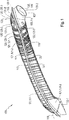
- Fig. 1 shows a perspective view of a fluid line 100 according to a first embodiment.
- the fluid line 100 in particular comprises a fluid line 100 for vehicles, in particular for motor vehicles with an internal combustion engine.
- Motor vehicles with internal combustion engines have fluid lines 100, which in particular comprise a charge air line, which is designed to supply charge air to the internal combustion engine.
- the charge air conducted through a charge air line can also contain impurities, e.g. Engine oil, fuel vapors, fuel condensates, exhaust gases, blowby gases and / or acids.
- impurities e.g. Engine oil, fuel vapors, fuel condensates, exhaust gases, blowby gases and / or acids.
- fluid lines 100 for conducting charge air must have sufficient chemical resistance to the conducted fluid. In order to be able to withstand the fluids conducted at high temperatures and high pressure, the corresponding fluid lines 100 must also have sufficient mechanical resistance.
- the fluid line 100 is designed according to the present disclosure to conduct fluid in a temperature range between 80 ° C. and 250 ° C. and / or fluid in a pressure range between 1 bar and 5 bar.
- the fluid line 100 has a plastic tube 101 for conducting a fluid.
- the fluid line 100 has a plastic grid 103 which surrounds the plastic pipe 101, the plastic pipe 101 and the plastic grid 103 being inseparably connected.
- the plastic grille 103 which is inseparably connected to the plastic tube 101, can also effectively reduce the tube thickness of the plastic tube 101 without the fluid line 100 having an adverse stability.
- the tube thickness of the plastic tube 101 according to the present disclosure is less than 2.5 mm, in particular less than 2.0 mm, in particular less than 1.5 mm.
- the fluid line 100 in accordance with the present disclosure enables an effective replacement of conventionally used metal pipes for conducting fluid, in particular for conducting charge air.
- the plastic grid 103 and the plastic tube 101 are made in one piece, in particular as an injection molded component, or the plastic grid 103 is integrally connected, in particular welded, to the plastic grid 103.
- the plastic tube 101 has a tube wall 105 which delimits a tube interior 107, the tube wall 105 having a wall interior 109 facing the tube interior 107 and a wall exterior 111 facing away from the tube interior 107, and wherein the plastic grid 103 is inseparable from the wall exterior 111 of the tube wall 105 connected is.
- the plastic grid 103 has a first grid section 103-1, which is arranged on an upper side 113 of the plastic tube 101, in particular on the outside of the wall 111, and the plastic grid 103 in particular has a second grid section 103-2, which is remote on an upper side 113 Underside 115 of the plastic tube 101, in particular the wall outside 111, is arranged.
- the plastic pipe 101 has a raw pipe shell 101-1 and a lower pipe shell 101-2, which are inseparably connected to one another, in particular a pipe flange 117 being arranged between the rough pipe shell 101-1 and the lower pipe shell 101-2, and the plastic grid 103 with the raw robot shell 101-1 and / or with the lower tube shell 101-2 is inseparably connected.
- the first grid section 103-1 is inseparably connected to the raw robot shell 101-1 and the second grid section 103-2 is inseparably connected to the lower pipe shell 101-2.
- the pipe flange 117 in particular runs around the plastic pipe 101 along a longitudinal axis 119 of the plastic pipe 101.
- the fluid line 100 has a plurality of side struts 121, which are inseparably connected to the plastic grid 103, in particular to the first and / or second grid section 103-1, 103-2, and the plastic pipe 101, the side struts 121 in particular being separated from one another the plastic grid 103 from along a lateral side 123 of the plastic tube 101, the lateral side 123 between the top 113 and the bottom 115 of the plastic tube 101 is arranged.
- the side struts 121 extend from the plastic grid 103 along the wall outside 111.
- the side struts 121 have a first side strut section 121-1 and a second side strut section 121-2, the second side strut section 121-2 extending at an angle to the first side strut section 121-1, in particular the first side strut section 121-1 on a wall outside 111 of the plastic tube 101 and in particular the second side strut section 121-2 abuts a tube flange 117 of the plastic tube 101.
- the side struts 121 thus ensure effective stabilization of the plastic tube 101.
- the plastic grid 103 has a plurality of grid struts 125, which have different strengths and / or different strut thicknesses 127 in some areas, the strut thicknesses 127 in Fig. 1 are not shown.
- the plastic grid 103 in particular the first and or second grid section 103-1, 103-2, has in particular a plurality of longitudinal struts 125-1 extending along a longitudinal axis 119 of the plastic tube 101, and / or a plurality of along a transverse axis 129 of the Plastic struts 101 extending transverse struts 125-2, and a plurality of diagonal struts 125-3 extending diagonally to a longitudinal axis 119 and transverse axis 129 of the plastic pipe 101, the plurality of longitudinal struts 125-1, cross struts 125-2 and / or diagonal struts 125 -3 especially cross each other.
- the plastic grid 103 in particular the first and second grid sections 103-1, 103-2, has first mounts 131-1 and second mounts 131-2.
- the first enclosures 131-1 are delimited by the lattice struts 125, in particular longitudinal struts 125-1, cross struts 125-2 and / or diagonal struts 125-3.
- the first surrounds 131-1 are delimited by the longitudinal struts 125-1, transverse struts 125-2 and diagonal struts 125-3, the diagonal struts 125-3 not passing through the first surrounds 131-1.
- the second Boundaries 131-2 delimited by the longitudinal struts 125-1 and transverse struts 125-2, the diagonal struts 125-3 passing through the second borders 131-2.
- the first and second borders 131-1, 131-2 of the plastic grid 103 are alternately arranged next to one another.
- the first and second borders 131-1, 131-2 of the plastic grid 103 form a checkerboard-like pattern.
- the plastic tube 101 is in particular designed as a plastic tube 101 that is bent relative to a longitudinal axis 119 of the plastic tube 101.
- the plastic tube 101 has, in particular, a first opening connection piece 133-1 and a second opening connection piece 133-2 facing away from the first opening connection piece 133-1, the first and / or second opening connection piece 133-1, 133-2 being in particular at an angle to the longitudinal axis 119 of the Plastic tube 101 extends. Fluid can be effectively introduced or discharged into the plastic tube 101 through the two opening sockets 133-1, 133-2.
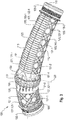
- Fig. 2 shows a perspective view of the fluid line according to the in Fig. 1 illustrated first embodiment.
- FIG. 2 shown view of the fluid line 100, the top 113 of the plastic tube 101, in particular the top 113 of the raw robot shell 101-1 of the plastic tube 101 is shown.
- the lower pipe shell 101-2 of the plastic pipe 101 is in the Fig. 2 only shown in sections.
- a pipe flange 117 is arranged between the raw pipe shell 101-1 and the lower pipe shell 101-2, which in particular rotates at least in sections around the plastic pipe 101 along a longitudinal axis 119 of the plastic pipe 101.
- the fluid line 100 also has a plastic grid 103 which is inseparably connected to the plastic tube 101.
- a plastic grid 103 which is inseparably connected to the plastic tube 101.
- a first grating section 103-1 of the plastic grating 103 arranged on the upper side 113 of the plastic tube 101 is shown.
- the fluid line 100 has a plurality of side struts 121, which are connected to the plastic grid 103, in particular to the in Fig. 2 shown first grid section 103-1, and the plastic tube 101 are inseparably connected.
- the side struts 121 extend in particular from the plastic grid 103 along a lateral side 123 of the plastic tube 101, the lateral side 123 being arranged between the upper side 113 and the lower side 115 of the plastic tube 101.
- the side struts 121 have a first side strut section 121-1 and a second side strut section 121-2, the second side strut section 121-2 extending at an angle to the first side strut section 121-1.
- the first side strut section 121-1 is in particular in contact with an outer wall 111 of the plastic tube 101.
- the second side strut section 121-2 lies in particular on the pipe flange 117 of the plastic pipe 101. Effective stabilization on the lateral side 123 of the plastic tube 101 can thus be ensured by the side struts 121.
- the plastic grid 103 arranged on the top 113 of the plastic tube 101 has a plurality of grid struts 125, which in particular have different strengths and / or different strut thicknesses 127 in certain areas.
- a strut thickness 127 of a lattice strut 125 is in the Fig. 2 shown as an example.
- the lattice struts 125 in particular have a plurality of longitudinal struts 125-1 extending along the longitudinal axis 119 of the plastic tube 101, and / or a plurality of cross struts 125-2 extending along a transverse axis 129 of the plastic tube 101, and / or a plurality of diagonally to a longitudinal axis 119 and transverse axis 129 of the plastic tube 101 extending diagonal struts 125-3, the plurality of longitudinal struts 125-1, cross struts 125-2 and / or diagonal struts 125-3 crossing one another in particular.
- the plastic grid 103 in particular the first grid section 103-1, has first mounts 131-1 and second mounts 131-2.
- the first enclosures 131-1 are delimited by the lattice struts 125, in particular longitudinal struts 125-1, cross struts 125-2 and diagonal struts 125-3.
- the second surrounds 131-2 are delimited by the lattice struts 125, in particular longitudinal struts 125-1 and transverse struts 125-2, the diagonal struts 125-3 passing through the second surrounds 131-2.
- first and second borders 131-1, 131-2 of the plastic grid 103 are alternately arranged next to one another.
- the first and second borders 131-1, 131-2 of the plastic grid 103 form a checkerboard pattern.
- Fig. 3 shows a perspective view of the fluid line according to a second embodiment.
- the in the Fig. 3 The second embodiment shown comprises a fluid line 100 with a plastic tube 101 and a plastic grid 103, which is inseparably connected to the plastic tube 101.
- the plastic grid 103 comprises a first grid section 103-1, which is arranged on an upper side 113 of the plastic tube 101, and comprises a second grid section 103-2, which is arranged on a lower side 115 of the plastic pipe 101.
- the fluid line 100 also has side struts 121 which are inseparably connected to the plastic tube 101 and the plastic grid 103.
- side struts 121 which are inseparably connected to the plastic tube 101 and the plastic grid 103.
- side struts 121 only a first side strut portion 121-1 abutting the wall outside 111 of the plastic tube 101.
- the in the Fig. 3 The side struts 121 shown do not have a second side strut section 121-2, since the plastic tube 101 has no tube flange 117 against which the side struts 121 rest.
- the illustrated side struts 121 extend along the wall outside 111 of the plastic tube 101 from the first grid section 103-1 along the lateral side 123 to the second grid section 103-2.
- Plastic grid 103 shown also has the in the Fig. 3 Plastic grid 103 shown extends along a longitudinal axis 119, longitudinal struts 125-1, cross struts 125-2 extending along a transverse axis 129 of the plastic tube 101, and diagonal struts 125-3 extending diagonally to the longitudinal axis 119 and the transverse axis 129.
- the plastic grid 103 in particular the first and second grid sections 103-1, 103-2, has first mounts 131-1 and second mounts 131-2.
- the first enclosures 131-1 are delimited by the lattice struts 125, in particular longitudinal struts 125-1, cross struts 125-2 and / or diagonal struts 125-3.
- the second surrounds 131-2 are delimited by the lattice struts 125, in particular longitudinal struts 125-1 and transverse struts 125-2, the diagonal struts 125-3 passing through the second surrounds 131-2.
- the in the Fig. 3 Fluid line 100 shown according to the first embodiment differs from that in FIGS Figures 1 and 2nd Fluid line 100 shown according to the second embodiment in that the plastic pipe 101 has a first pipe section 101-3 and a second pipe section 101-4, which are connected to one another by a welding area 135.
- the welding area 135 runs around the plastic pipe 101, in particular along a transverse axis 129, of the plastic pipe 101.
- the plastic grid 103 is inseparably connected to the first and / or second pipe section 101-3, 101-4.
- the welding area 135 comprises in particular a plurality of stabilizing ribs 137 which run around the plastic tube 101, in particular along the transverse axis 129.
- the stabilizing ribs 137 are stabilized in particular by longitudinal ribs 139 extending along the longitudinal axis 119.
- the plastic pipe 101 in particular the first and second pipe sections 101-3, 101-4, is in particular designed as a plastic pipe 101 bent with respect to a longitudinal axis 119 of the plastic pipe 101.
- the plastic pipe 101 in particular the first pipe section 101-3, in particular has a first opening stub 133-1.
- the plastic pipe 101, in particular the second pipe section 101-4 has a second opening stub 133-2 facing away from the first opening stub 133-1.
- the first and / or second opening connection piece 133-1, 133-2 has in particular a hose connection piece.
Landscapes
- Engineering & Computer Science (AREA)
- General Engineering & Computer Science (AREA)
- Mechanical Engineering (AREA)
- Chemical & Material Sciences (AREA)
- Combustion & Propulsion (AREA)
- Rigid Pipes And Flexible Pipes (AREA)
Applications Claiming Priority (1)
| Application Number | Priority Date | Filing Date | Title |
|---|---|---|---|
| DE102018122988.7A DE102018122988A1 (de) | 2018-09-19 | 2018-09-19 | Fluidleitung zum leiten eines fluids |
Publications (1)
| Publication Number | Publication Date |
|---|---|
| EP3640468A1 true EP3640468A1 (fr) | 2020-04-22 |
Family
ID=67659416
Family Applications (1)
| Application Number | Title | Priority Date | Filing Date |
|---|---|---|---|
| EP19192488.5A Pending EP3640468A1 (fr) | 2018-09-19 | 2019-08-20 | Conduite de fluide destinée à conduire un fluide |
Country Status (2)
| Country | Link |
|---|---|
| EP (1) | EP3640468A1 (fr) |
| DE (1) | DE102018122988A1 (fr) |
Families Citing this family (1)
| Publication number | Priority date | Publication date | Assignee | Title |
|---|---|---|---|---|
| US12326126B2 (en) * | 2022-08-29 | 2025-06-10 | Subaru Corporation | Resonator structure |
Citations (6)
| Publication number | Priority date | Publication date | Assignee | Title |
|---|---|---|---|---|
| DE102004029221A1 (de) * | 2004-06-16 | 2006-01-12 | Geiger Technik Gmbh | Vorrichtung zur Schalldämpfung und Vorrichtung zur Leitung eines Fluids |
| EP1777061A2 (fr) * | 2005-10-21 | 2007-04-25 | Lisa Dräxlmaier GmbH | Procédé pour fabriquer des corps creux en matière plastique |
| EP2754881A1 (fr) * | 2011-09-05 | 2014-07-16 | Roki Co., Ltd. | Conduit d'aspiration |
| CN204126784U (zh) * | 2014-10-20 | 2015-01-28 | 安徽江淮汽车股份有限公司 | 一种汽车空滤器的出气管总成以及空滤器 |
| KR101782448B1 (ko) * | 2016-04-18 | 2017-09-27 | 코리아웨코스타 주식회사 | 차량용 패치형 흡기덕트 및 그 제조방법 |
| KR101814468B1 (ko) * | 2017-05-02 | 2018-01-05 | 주식회사 화승알앤에이 | 보강용 구조물 및 보강용 구조물을 포함하는 호스 |
-
2018
- 2018-09-19 DE DE102018122988.7A patent/DE102018122988A1/de active Pending
-
2019
- 2019-08-20 EP EP19192488.5A patent/EP3640468A1/fr active Pending
Patent Citations (6)
| Publication number | Priority date | Publication date | Assignee | Title |
|---|---|---|---|---|
| DE102004029221A1 (de) * | 2004-06-16 | 2006-01-12 | Geiger Technik Gmbh | Vorrichtung zur Schalldämpfung und Vorrichtung zur Leitung eines Fluids |
| EP1777061A2 (fr) * | 2005-10-21 | 2007-04-25 | Lisa Dräxlmaier GmbH | Procédé pour fabriquer des corps creux en matière plastique |
| EP2754881A1 (fr) * | 2011-09-05 | 2014-07-16 | Roki Co., Ltd. | Conduit d'aspiration |
| CN204126784U (zh) * | 2014-10-20 | 2015-01-28 | 安徽江淮汽车股份有限公司 | 一种汽车空滤器的出气管总成以及空滤器 |
| KR101782448B1 (ko) * | 2016-04-18 | 2017-09-27 | 코리아웨코스타 주식회사 | 차량용 패치형 흡기덕트 및 그 제조방법 |
| KR101814468B1 (ko) * | 2017-05-02 | 2018-01-05 | 주식회사 화승알앤에이 | 보강용 구조물 및 보강용 구조물을 포함하는 호스 |
Also Published As
| Publication number | Publication date |
|---|---|
| DE102018122988A1 (de) | 2020-03-19 |
Similar Documents
| Publication | Publication Date | Title |
|---|---|---|
| DE10348575B4 (de) | Abgasrückführsystem für einen Verbrennungsmotor | |
| DE102013003753A1 (de) | Filter, Filterelement und Filtergehäuse | |
| DE112012003317B4 (de) | EGR-Vorrichtung für Verbrennungsmotor | |
| DE202008014511U1 (de) | Filtereinrichtung, insbesondere Luftfilter | |
| DE19701977A1 (de) | Brennkraftmaschine mit einem Ventilkammerdeckel | |
| DE102015012505A1 (de) | Dichtungsanordnung für eine Anschlussvorrichtung und Anschlussvorrichtung für eine Klimaanlage | |
| DE102007050655A1 (de) | Wellenschlauch | |
| DE102018122988A1 (de) | Fluidleitung zum leiten eines fluids | |
| EP2639423B1 (fr) | Silencieux d'échappement | |
| EP1520977B1 (fr) | Dispositif d'admission pour un dispositif de prépurification en connection avec une enveloppe de ventilateur | |
| DE60123350T2 (de) | Zylinderkopfdeckel für eine Brennmaschine | |
| EP1283351B1 (fr) | Système d'admission pour un moteur à combustion interne | |
| DE102018216737A1 (de) | Ventil, Ölabscheider sowie Entlüftungssystem | |
| DE102021131859A1 (de) | Luftleitbaugruppe | |
| WO2025108671A1 (fr) | Élément filtrant, en particulier pour filtration de gaz | |
| DE102012216531A1 (de) | Ölabscheideranordnung für einen Verbrennungsmotor | |
| DE102017116807A1 (de) | Luftkanalsystem | |
| DE102008038052A1 (de) | Dichtungsanordnung | |
| DE2739290A1 (de) | Gasfilter | |
| DE102019117640A1 (de) | Rohrbauteil | |
| DE102017116410A1 (de) | AUSSTOßVENTIL MIT VERLÄNGERUNGSROHR ZUM SPÜLEN VON BRENNSTOFFZELLEN | |
| WO2017144129A1 (fr) | Système d'étanchéité pour un composant de moteur et composant de moteur pourvu de ce système d'étanchéité | |
| DE102023128199A1 (de) | Ansaugkrümmer | |
| DE102019101498A1 (de) | Ansaugkrümmer für einen Verbrennungsmotor | |
| DE102018124954A1 (de) | Rohreinheit-Kopplungsstruktur |
Legal Events
| Date | Code | Title | Description |
|---|---|---|---|
| PUAI | Public reference made under article 153(3) epc to a published international application that has entered the european phase |
Free format text: ORIGINAL CODE: 0009012 |
|
| STAA | Information on the status of an ep patent application or granted ep patent |
Free format text: STATUS: THE APPLICATION HAS BEEN PUBLISHED |
|
| AK | Designated contracting states |
Kind code of ref document: A1 Designated state(s): AL AT BE BG CH CY CZ DE DK EE ES FI FR GB GR HR HU IE IS IT LI LT LU LV MC MK MT NL NO PL PT RO RS SE SI SK SM TR |
|
| AX | Request for extension of the european patent |
Extension state: BA ME |
|
| STAA | Information on the status of an ep patent application or granted ep patent |
Free format text: STATUS: REQUEST FOR EXAMINATION WAS MADE |
|
| 17P | Request for examination filed |
Effective date: 20201005 |
|
| RBV | Designated contracting states (corrected) |
Designated state(s): AL AT BE BG CH CY CZ DE DK EE ES FI FR GB GR HR HU IE IS IT LI LT LU LV MC MK MT NL NO PL PT RO RS SE SI SK SM TR |
|
| STAA | Information on the status of an ep patent application or granted ep patent |
Free format text: STATUS: EXAMINATION IS IN PROGRESS |
|
| 17Q | First examination report despatched |
Effective date: 20220104 |
|
| P01 | Opt-out of the competence of the unified patent court (upc) registered |
Effective date: 20230515 |
|
| GRAP | Despatch of communication of intention to grant a patent |
Free format text: ORIGINAL CODE: EPIDOSNIGR1 |
|
| STAA | Information on the status of an ep patent application or granted ep patent |
Free format text: STATUS: GRANT OF PATENT IS INTENDED |
|
| INTG | Intention to grant announced |
Effective date: 20250217 |
|
| 19U | Interruption of proceedings before grant |
Effective date: 20200728 |
|
| 19W | Proceedings resumed before grant after interruption of proceedings |
Effective date: 20260102 |