EP3639757A2 - Mécanisme de découplage pour agrafeuse chirurgicale linéaire - Google Patents
Mécanisme de découplage pour agrafeuse chirurgicale linéaire Download PDFInfo
- Publication number
- EP3639757A2 EP3639757A2 EP19204124.2A EP19204124A EP3639757A2 EP 3639757 A2 EP3639757 A2 EP 3639757A2 EP 19204124 A EP19204124 A EP 19204124A EP 3639757 A2 EP3639757 A2 EP 3639757A2
- Authority
- EP
- European Patent Office
- Prior art keywords
- proximal
- surgical stapler
- elongate
- anvil
- distal
- Prior art date
- Legal status (The legal status is an assumption and is not a legal conclusion. Google has not performed a legal analysis and makes no representation as to the accuracy of the status listed.)
- Granted
Links
- 230000007246 mechanism Effects 0.000 title claims abstract description 35
- 230000004044 response Effects 0.000 claims abstract description 17
- 238000010168 coupling process Methods 0.000 claims description 13
- 230000008878 coupling Effects 0.000 claims description 12
- 238000005859 coupling reaction Methods 0.000 claims description 12
- 238000010304 firing Methods 0.000 description 90
- 210000003811 finger Anatomy 0.000 description 54
- 238000000034 method Methods 0.000 description 11
- 239000000463 material Substances 0.000 description 10
- 230000003872 anastomosis Effects 0.000 description 6
- 238000000926 separation method Methods 0.000 description 6
- 230000006870 function Effects 0.000 description 5
- 230000014509 gene expression Effects 0.000 description 5
- 230000005855 radiation Effects 0.000 description 4
- 230000000717 retained effect Effects 0.000 description 4
- 238000004140 cleaning Methods 0.000 description 3
- 239000012636 effector Substances 0.000 description 3
- 230000003993 interaction Effects 0.000 description 3
- 230000004048 modification Effects 0.000 description 3
- 238000012986 modification Methods 0.000 description 3
- 238000001356 surgical procedure Methods 0.000 description 3
- 230000002496 gastric effect Effects 0.000 description 2
- 238000011282 treatment Methods 0.000 description 2
- 241000894006 Bacteria Species 0.000 description 1
- IAYPIBMASNFSPL-UHFFFAOYSA-N Ethylene oxide Chemical compound C1CO1 IAYPIBMASNFSPL-UHFFFAOYSA-N 0.000 description 1
- 239000004775 Tyvek Substances 0.000 description 1
- 229920000690 Tyvek Polymers 0.000 description 1
- 230000009471 action Effects 0.000 description 1
- 230000006978 adaptation Effects 0.000 description 1
- 238000013459 approach Methods 0.000 description 1
- 230000000712 assembly Effects 0.000 description 1
- 238000000429 assembly Methods 0.000 description 1
- 230000008901 benefit Effects 0.000 description 1
- 230000000295 complement effect Effects 0.000 description 1
- 230000007423 decrease Effects 0.000 description 1
- 230000003247 decreasing effect Effects 0.000 description 1
- 230000000881 depressing effect Effects 0.000 description 1
- 210000004247 hand Anatomy 0.000 description 1
- 238000003780 insertion Methods 0.000 description 1
- 230000037431 insertion Effects 0.000 description 1
- 230000002452 interceptive effect Effects 0.000 description 1
- 238000002955 isolation Methods 0.000 description 1
- 238000004806 packaging method and process Methods 0.000 description 1
- 230000011664 signaling Effects 0.000 description 1
- 230000001954 sterilising effect Effects 0.000 description 1
- 238000004659 sterilization and disinfection Methods 0.000 description 1
- 210000003813 thumb Anatomy 0.000 description 1
- 238000013519 translation Methods 0.000 description 1
Images


Classifications
-
- A—HUMAN NECESSITIES
- A61—MEDICAL OR VETERINARY SCIENCE; HYGIENE
- A61B—DIAGNOSIS; SURGERY; IDENTIFICATION
- A61B17/00—Surgical instruments, devices or methods, e.g. tourniquets
- A61B17/068—Surgical staplers, e.g. containing multiple staples or clamps
- A61B17/072—Surgical staplers, e.g. containing multiple staples or clamps for applying a row of staples in a single action, e.g. the staples being applied simultaneously
- A61B17/07207—Surgical staplers, e.g. containing multiple staples or clamps for applying a row of staples in a single action, e.g. the staples being applied simultaneously the staples being applied sequentially
-
- A—HUMAN NECESSITIES
- A61—MEDICAL OR VETERINARY SCIENCE; HYGIENE
- A61B—DIAGNOSIS; SURGERY; IDENTIFICATION
- A61B17/00—Surgical instruments, devices or methods, e.g. tourniquets
- A61B17/068—Surgical staplers, e.g. containing multiple staples or clamps
-
- A—HUMAN NECESSITIES
- A61—MEDICAL OR VETERINARY SCIENCE; HYGIENE
- A61B—DIAGNOSIS; SURGERY; IDENTIFICATION
- A61B17/00—Surgical instruments, devices or methods, e.g. tourniquets
- A61B17/28—Surgical forceps
- A61B17/2812—Surgical forceps with a single pivotal connection
- A61B17/2833—Locking means
-
- A—HUMAN NECESSITIES
- A61—MEDICAL OR VETERINARY SCIENCE; HYGIENE
- A61B—DIAGNOSIS; SURGERY; IDENTIFICATION
- A61B17/00—Surgical instruments, devices or methods, e.g. tourniquets
- A61B2017/00367—Details of actuation of instruments, e.g. relations between pushing buttons, or the like, and activation of the tool, working tip, or the like
-
- A—HUMAN NECESSITIES
- A61—MEDICAL OR VETERINARY SCIENCE; HYGIENE
- A61B—DIAGNOSIS; SURGERY; IDENTIFICATION
- A61B17/00—Surgical instruments, devices or methods, e.g. tourniquets
- A61B2017/0042—Surgical instruments, devices or methods, e.g. tourniquets with special provisions for gripping
-
- A—HUMAN NECESSITIES
- A61—MEDICAL OR VETERINARY SCIENCE; HYGIENE
- A61B—DIAGNOSIS; SURGERY; IDENTIFICATION
- A61B17/00—Surgical instruments, devices or methods, e.g. tourniquets
- A61B2017/00477—Coupling
-
- A—HUMAN NECESSITIES
- A61—MEDICAL OR VETERINARY SCIENCE; HYGIENE
- A61B—DIAGNOSIS; SURGERY; IDENTIFICATION
- A61B17/00—Surgical instruments, devices or methods, e.g. tourniquets
- A61B2017/00526—Methods of manufacturing
-
- A—HUMAN NECESSITIES
- A61—MEDICAL OR VETERINARY SCIENCE; HYGIENE
- A61B—DIAGNOSIS; SURGERY; IDENTIFICATION
- A61B17/00—Surgical instruments, devices or methods, e.g. tourniquets
- A61B2017/00831—Material properties
- A61B2017/00862—Material properties elastic or resilient
-
- A—HUMAN NECESSITIES
- A61—MEDICAL OR VETERINARY SCIENCE; HYGIENE
- A61B—DIAGNOSIS; SURGERY; IDENTIFICATION
- A61B17/00—Surgical instruments, devices or methods, e.g. tourniquets
- A61B2017/00982—General structural features
- A61B2017/00991—Telescopic means
-
- A—HUMAN NECESSITIES
- A61—MEDICAL OR VETERINARY SCIENCE; HYGIENE
- A61B—DIAGNOSIS; SURGERY; IDENTIFICATION
- A61B17/00—Surgical instruments, devices or methods, e.g. tourniquets
- A61B17/068—Surgical staplers, e.g. containing multiple staples or clamps
- A61B17/072—Surgical staplers, e.g. containing multiple staples or clamps for applying a row of staples in a single action, e.g. the staples being applied simultaneously
- A61B2017/07214—Stapler heads
- A61B2017/0725—Stapler heads with settable gap between anvil and cartridge, e.g. for different staple heights at different shots
-
- A—HUMAN NECESSITIES
- A61—MEDICAL OR VETERINARY SCIENCE; HYGIENE
- A61B—DIAGNOSIS; SURGERY; IDENTIFICATION
- A61B17/00—Surgical instruments, devices or methods, e.g. tourniquets
- A61B17/068—Surgical staplers, e.g. containing multiple staples or clamps
- A61B17/072—Surgical staplers, e.g. containing multiple staples or clamps for applying a row of staples in a single action, e.g. the staples being applied simultaneously
- A61B2017/07214—Stapler heads
- A61B2017/07257—Stapler heads characterised by its anvil
- A61B2017/07264—Stapler heads characterised by its anvil characterised by its staple forming cavities, e.g. geometry or material
-
- A—HUMAN NECESSITIES
- A61—MEDICAL OR VETERINARY SCIENCE; HYGIENE
- A61B—DIAGNOSIS; SURGERY; IDENTIFICATION
- A61B17/00—Surgical instruments, devices or methods, e.g. tourniquets
- A61B17/068—Surgical staplers, e.g. containing multiple staples or clamps
- A61B17/072—Surgical staplers, e.g. containing multiple staples or clamps for applying a row of staples in a single action, e.g. the staples being applied simultaneously
- A61B2017/07214—Stapler heads
- A61B2017/07271—Stapler heads characterised by its cartridge
-
- A—HUMAN NECESSITIES
- A61—MEDICAL OR VETERINARY SCIENCE; HYGIENE
- A61B—DIAGNOSIS; SURGERY; IDENTIFICATION
- A61B17/00—Surgical instruments, devices or methods, e.g. tourniquets
- A61B17/068—Surgical staplers, e.g. containing multiple staples or clamps
- A61B17/072—Surgical staplers, e.g. containing multiple staples or clamps for applying a row of staples in a single action, e.g. the staples being applied simultaneously
- A61B2017/07214—Stapler heads
- A61B2017/07278—Stapler heads characterised by its sled or its staple holder
-
- A—HUMAN NECESSITIES
- A61—MEDICAL OR VETERINARY SCIENCE; HYGIENE
- A61B—DIAGNOSIS; SURGERY; IDENTIFICATION
- A61B17/00—Surgical instruments, devices or methods, e.g. tourniquets
- A61B17/068—Surgical staplers, e.g. containing multiple staples or clamps
- A61B17/072—Surgical staplers, e.g. containing multiple staples or clamps for applying a row of staples in a single action, e.g. the staples being applied simultaneously
- A61B2017/07214—Stapler heads
- A61B2017/07285—Stapler heads characterised by its cutter
-
- A—HUMAN NECESSITIES
- A61—MEDICAL OR VETERINARY SCIENCE; HYGIENE
- A61B—DIAGNOSIS; SURGERY; IDENTIFICATION
- A61B17/00—Surgical instruments, devices or methods, e.g. tourniquets
- A61B17/28—Surgical forceps
- A61B17/29—Forceps for use in minimally invasive surgery
- A61B2017/2926—Details of heads or jaws
- A61B2017/2927—Details of heads or jaws the angular position of the head being adjustable with respect to the shaft
-
- A—HUMAN NECESSITIES
- A61—MEDICAL OR VETERINARY SCIENCE; HYGIENE
- A61B—DIAGNOSIS; SURGERY; IDENTIFICATION
- A61B17/00—Surgical instruments, devices or methods, e.g. tourniquets
- A61B17/32—Surgical cutting instruments
- A61B2017/320044—Blunt dissectors
-
- A—HUMAN NECESSITIES
- A61—MEDICAL OR VETERINARY SCIENCE; HYGIENE
- A61B—DIAGNOSIS; SURGERY; IDENTIFICATION
- A61B90/00—Instruments, implements or accessories specially adapted for surgery or diagnosis and not covered by any of the groups A61B1/00 - A61B50/00, e.g. for luxation treatment or for protecting wound edges
- A61B90/08—Accessories or related features not otherwise provided for
- A61B2090/0807—Indication means
- A61B2090/0811—Indication means for the position of a particular part of an instrument with respect to the rest of the instrument, e.g. position of the anvil of a stapling instrument
Definitions
- a linear surgical stapler generally includes a first half (referred to as a “cartridge half” or “reload half”) having a distal jaw configured to support a staple cartridge (or “reload”), and a second half (referred to as an “anvil half”) having a distal jaw that supports an anvil surface having staple forming features.
- the stapler further includes a moveable clamp lever configured to releasably clamp the stapler halves together.
- the stapler halves are configured to pivot relative to one another to receive and clamp tissue between the two distal jaws when the clamp lever is closed.
- a firing assembly of the stapler is configured to be actuated to cut the clamped layers and simultaneously drive staples through the tissue on either side of the cut line. After firing the stapler, the clamp lever may be opened, and the stapler halves separated to release the severed and stapled tissue.
- proximal and distal are defined herein relative to a surgeon, or other operator, grasping a surgical instrument having a distal surgical end effector.
- proximal refers to the position of an element arranged closer to the surgeon
- distal refers to the position of an element arranged closer to the surgical end effector of the surgical instrument and further away from the surgeon.
- spatial terms such as “upper,” “lower,” “vertical,” “horizontal,” or the like are used herein with reference to the drawings, it will be appreciated that such terms are used for exemplary description purposes only and are not intended to be limiting or absolute. In that regard, it will be understood that surgical instruments such as those disclosed herein may be used in a variety of orientations and positions not limited to those shown and described herein.
- FIGS. 1 and 2 show an exemplary linear surgical stapler (10) (also referred to as a "linear cutter”) suitable for use in a variety of cutting and stapling procedures, such as a gastrointestinal anastomosis procedure.
- Linear surgical stapler (10) includes a cartridge half (12) (also referred to as a “reload half”) and an anvil half (14) configured to releasably couple together to clamp tissue therebetween.
- Cartridge half (12) includes an elongate cartridge channel (16) having a proximal frame portion (18) that slidably retains a portion of a firing assembly (34), a distal jaw portion (20) that supports a staple cartridge (80) (or “reload”), and a pair of upright side flanges (22) arranged medially therebetween.
- Cartridge half (12) further includes a clamp lever (24) pivotably coupled to an underside of cartridge channel (16) in approximate alignment with side flanges (22).
- Clamp lever (24) includes an elongate lever arm (26) having a free proximal end and a distal end that is pivotably coupled to cartridge channel (16) with a pivot pin (28).
- a pair of opposed jaws (30) extends distally from the distal end of lever arm (26) alongside flanges (22) of cartridge channel (16).
- Each jaw (30) includes a respective elongate slot (32) having a closed proximal end and an open distal end, and which defines upper and lower camming surfaces configured to engage a respective latch projection (56) of anvil half (14).
- clamp lever (24) is operable to pivot relative to cartridge channel (16) between open and closed positions to releasably clamp anvil half (14) against cartridge half (12) and thereby capture tissue layers therebetween.
- firing assembly (34) of cartridge half (12) includes a slider block (36) slidably retained within proximal frame portion (18) of cartridge channel (16), an actuator (38) (or “firing knob") movably coupled with slider block (36), and an elongate actuating beam (not shown) extending distally from slider block (36) and configured to couple with a sled (100) (see FIG. 3 ) housed within staple cartridge (80).
- Actuator (38) of the present example is configured to pivot about the proximal end of cartridge half (12) to provide for "dual-sided firing" of stapler (10).
- actuator (38) may be positioned along either lateral side of cartridge half (12) to perform a distal firing stroke, such that stapler (10) may be conveniently fired in a variety of orientations during a surgical procedure.
- Slider block (36) is configured to be translatably driven within proximal frame portion (18) by actuator (38) between a proximal home position shown in FIGS. 2 and 5A , and a distal fired position shown in FIG. 5B .
- actuator (38) In the proximal home position, slider block (36) abuts a post (40) fixed at a proximal end of cartridge channel (16).
- a free end of post (40) supports a laterally extending pivot pin (42).
- actuator (38) may be driven distally when stapler halves (12, 14) are fully coupled together and clamp lever (24) is closed.
- Distal advancement of actuator (38) along either lateral side of stapler (10) drives slider block (36) and the elongate actuating beam distally, which in turn drives sled (100) distally through staple cartridge (80).
- sled (100) distally through staple cartridge (80)
- distal translation of sled (100) through staple cartridge (80) provides for simultaneous stapling and cutting of tissue clamped between stapler halves (12, 14).
- anvil half (14) of linear surgical stapler (10) includes an elongate anvil channel (50) having a proximal frame portion (52) and a distal jaw portion (54).
- Anvil channel (50) further includes a latch feature in the form of a pair of projections (56) that extend transversely from a medial portion of anvil channel (50) in a direction toward cartridge half (12).
- Each latch projection (56) may include a circular rotating cap configured to be captured within the slot (32) of a respective clamp lever jaw (30) when anvil half (14) is coupled with cartridge half (12) and clamp lever (24) is pivoted from the open position to the closed position, as described below.
- a pair of hooks (58) extend proximally from a proximal end of frame portion (52) and are configured to releasably capture opposed lateral ends of proximal pivot pin (42) of cartridge half (12).
- Distal jaw portion (54) supports an anvil surface in the form of an anvil plate (60) having a plurality of staple forming pockets (not shown), and additionally supports a distal tip member (62).
- the anvil surface may be formed integrally with or otherwise be rigidly connected to distal jaw portion (54) of anvil channel (50).
- Anvil half (14) of the present example further includes a staple height adjustment mechanism (64) mounted to a medial portion of anvil channel (50).
- Staple height adjustment mechanism (64) is operatively coupled with anvil plate (60), for example via one or more camming features (not shown), and includes a pair of user-engageable projections (66). Longitudinal adjustment of projections (66) between a plurality of predetermined positions causes anvil plate (60) to move transversely relative to distal jaw portion (54) of anvil channel (50). This enables adjustment of a transverse gap distance between anvil plate (60) and a deck (94) of staple cartridge (80) that defines the height of staples being formed.
- staple height adjustment mechanism (64) may be omitted in some versions, in which case the anvil surface may be fixed relative to anvil channel (50). For instance, the anvil surface may be formed integrally with or otherwise fixedly secured to distal jaw portion (54).
- linear surgical stapler (10) further includes a plurality of shrouds (70, 72, 74) that cover select portions of stapler (10) and promote effective grip and manipulation of stapler (10) by an operator during use.
- cartridge half (12) includes a first shroud (70) that covers an outwardly facing side of proximal frame portion (18) of cartridge channel (16).
- Cartridge half (12) further includes a second shroud (72) that covers an outwardly facing side of clamp lever (24) and is configured to pivot with clamp lever (24) relative to cartridge channel (16) and first shroud (70).
- Anvil half (14) includes a third shroud (74) that covers an outwardly facing side of proximal frame portion (52) of anvil channel (50), including proximal hooks (58).
- Each shroud (70, 72, 74) may be coupled with its respective components of stapler (10) by any suitable means apparent to those of ordinary skill in the art. Additionally, each shroud (70, 72, 74) may be formed of one or more materials and be provided with texturing suitable to promote effective gripping of the shroud (70, 72, 74) by an operator to enable safe and efficient use of stapler (10) during a surgical procedure.
- staple cartridge (80) of the present example is an assembly that comprises a cartridge body (82), a pan (84) that covers an open lower side of cartridge body (82), and a plurality of staple drivers (86) housed within cartridge body (82) and each being configured to drive a respective staple (88).
- Cartridge body (82) includes a proximal end having coupling features (90) configured to releasably engage corresponding coupling features (not shown) of distal jaw portion (20) of cartridge channel (16), and a distal end defining a tapered nose (92).
- An upper side of cartridge body (82) defines a generally planar deck (94) through which a longitudinal slot (96) and a plurality of staple cavities (98) open.
- Each staple cavity (98) houses a respective staple driver (86) and a staple (88).
- an interior of cartridge body (82) slidably houses a sled (100) that comprises a sled body (102) and knife member (104). Lateral sides of sled body (102) support a plurality of cam ramps (106) that taper distally.
- a proximal end of sled body (102) includes a downwardly extending tab (108) configured to lockingly engage a distal end of the elongate actuating beam (not shown) of firing assembly (34) when staple cartridge (80) is mounted to cartridge half (12) of stapler (10).
- Knife member (104) extends upwardly from an upper side of sled body (102) and presents a distally facing cutting edge (110) configured to cut tissue.
- Sled (100) is configured to translate distally through cartridge body (82) in response to distal actuation of firing assembly (34), such that knife member (104) translates distally through longitudinal slot (96) to cut tissue clamped between stapler halves (12, 14).
- cam ramps (106) translate distally through respective interior slots (not shown) of cartridge body (82) to actuate staple drivers (86) and staples (88) upwardly through staple cavities (98) so that free ends of staples (88) pierce through the clamped tissue and deform against staple forming pockets of anvil plate (60).
- distal actuation of firing assembly (34) provides for simultaneous severing and stapling of tissue clamped between the distal end effector portions of stapler halves (12, 14).
- Linear surgical stapler (10) and staple cartridge (80) may be further configured and operable in accordance with one or more teachings of U.S. Pat. 7,905,381 , entitled “Surgical Stapling Instrument with Cutting Member Arrangement,” issued March 15, 2011; U.S. Pat. No. 7,954,686 , entitled “Surgical Stapler with Apparatus for Adjusting Staple Height,” issued June 7, 2011; U.S. Pat. No. 8,348,129 , entitled “Surgical Stapler Having A Closure Mechanism,” issued January 8, 2013; and/or U.S. Pat. No. 8,789,740 , entitled “Linear Cutting and Stapling Device with Selectively Disengageable Cutting Member,” issued July 29, 2014.
- the disclosure of each of these references is incorporated by reference herein.
- FIGS. 4A-4C show exemplary coupling of stapler halves (12, 14) during a surgical procedure.
- the proximal end of anvil half (14) is aligned with the proximal end of cartridge half (12) such that proximal pivot pin (42) of cartridge half (12) is received by proximal hooks (58) of anvil half (14).
- anvil half (14) With clamp lever (24) in the open position, anvil half (14) is then pivoted toward cartridge half (12), about proximal pivot pin (42), to direct latch projections of anvil half (14) into slots (32) of clamp lever jaws (30). Once latch projections (56) are received by clamp lever jaws (30), clamp lever (24) is pivoted toward the partially closed position shown in FIG. 4B .
- anvil half (14) is partially clamped with cartridge half (12) such that stapler (10) may now be held with a single hand without halves (12, 14) undesirably separating from one another. Additionally, in this state, the distal portions of stapler halves (12, 14) remain spaced apart from one another to permit positioning of tissue between the distal portions. It will be appreciated that tissue may be positioned between the distal portions of stapler halves (12, 14) before or upon achieving this partially clamped state.
- clamp lever (24) is then pivoted further toward its fully closed position such that the camming surfaces of clamp lever jaws (30) draw latch projections of anvil half (14) proximally against the closed proximal ends of slots (32) of clamp lever jaws (30), thereby fully clamping stapler halves (12, 14) together with tissue positioned securely therebetween.
- actuator (38) may be manipulated to fire staple cartridge (80).
- actuator (38) is pivoted about the proximal end of stapler (10) to overlie one of the lateral sides of stapler (10).
- Actuator (38) is then driven distally to actuate firing assembly (34) in the manner described above and thereby simultaneously sever and staple the clamped tissue.
- actuator (38) may be returned to its proximal home position shown in FIG. 2 , and clamp lever (24) may then be opened to separate stapler halves (12, 14) from one another and release the stapled and severed tissue.
- clamp lever (24) must be actuated from its fully open position to at least a partially closed position in which lever jaws (30) initially capture latch projections (56) of anvil half (14) in order to prevent separation of anvil half (14) from cartridge half (12).
- this initial coupling process requires the use of both hands of an operator, thus preventing the operator from being able to mount tissue to stapler (10) when clamp lever (24) is fully opened. Because it is generally easier to mount tissue to stapler halves (12, 14) while clamp lever (24) is fully opened, thus allowing the distal portions of stapler halves (12, 14) to be spaced further apart from one another, the operator will often enlist the help of an assistant in a "4-hands" assembly approach.
- an operator may be able to mount tissue to the separate halves of a linear surgical stapler with the clamp lever in a fully open position and without the aid of an assistant, such that the operator may use a first hand to hold the stapler and a second hand to position tissue relative to the stapler.
- the exemplary stapler (200) described below includes features that enable proximal ends of the first and second stapler halves to remain coupled together while the clamp lever is in a fully open position. This configuration enables the operator to suitably manipulate stapler (200) with a first hand, while leaving the other hand free to manipulate tissue relative to stapler (200).
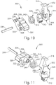
- FIGS. 6 and 7 show another exemplary linear surgical stapler (200) (or “linear cutter”) that is generally similar to linear surgical stapler (10) described above except as otherwise described below.
- Linear surgical stapler (200) includes a cartridge half (202) (or “reload half”) and an anvil half (204) configured to releasably couple together to clamp tissue therebetween for simultaneous cutting and stapling of the clamped tissue.
- Cartridge half (202) includes an elongate cartridge channel (206) having a proximal frame portion (208) and a distal jaw portion (210).
- Proximal frame portion (208) slidably retains a firing assembly (350) and includes a laterally opposed pair of upright side flanges (212).
- Each side flange (212) includes a vertical slot (214) arranged at a distal end thereof, and a tapered notch (216) arranged at a proximal end thereof.
- An outwardly projecting stiffening rib (218) extends longitudinally between distal slot (214) and the proximal notch (216) of each side flange (212) and is configured to provide the side flange (212) with enhanced stiffness.
- An outwardly flared upper segment (220) defines an upper edge of a proximal portion of each side flange (212) and is configured to facilitate receipt of anvil half (204) by cartridge half (202), as described in greater detail below.
- Each side flange (212) further includes an elongate firing slot (222) extending longitudinally between proximal notch (216) and distal slot (214) along a lower side of side flange (212). Elongate firing slots (222) are configured to guide firing assembly (350) between proximal and distal positions. Firing assembly (350) is described in greater detail below in connection with FIGS. 16-21 .
- Distal jaw portion (210) of cartridge channel (206) is configured to receive a staple cartridge (230) (or "reload"), which may be similar to staple cartridge (80) described above except as otherwise described below.
- Staple cartridge (230) includes a cartridge body (232) that houses a plurality of staple drivers and staples (not shown) similar to staple drivers (86) and staples (88).
- Cartridge body (232) further includes a longitudinal slot (234) configured to slidably receive a knife member (366) (see FIG. 16 ) of firing assembly (350), and a pair of interior slots (not shown) configured to slidably receive a pair of cam ramps (360) (see FIG. 16 ) of firing assembly (350).
- staple cartridge (230) and firing assembly (350) may be alternatively configured such that knife member (366) and cam ramps (360) are housed within cartridge body (232), similar to staple cartridge (80).
- Staple cartridge (230) of the present version further includes a pair of proximal coupling legs (236) configured to be directed through an opening (not shown) in a lower wall of cartridge channel (206) and releasably couple to a clamp lever pivot pin (242) with a snap-fit engagement.
- Cartridge half (202) further includes a clamp lever (240) pivotably coupled to cartridge channel (206) with clamp lever pivot pin (242), which is arranged in approximate alignment with distal slots (214) of cartridge channel side flanges (212).
- Clamp lever (240) includes an elongate lever arm (244) having a free proximal end (246) and a distal end that is pivotably coupled to a lower portion of cartridge channel (206) with pivot pin (242).
- a pair of opposed jaws (248) extend distally from the distal end of lever arm (244) alongside cartridge channel side flanges (212).
- Each jaw (248) includes a curved slot (250) having a closed proximal end and an open distal end configured to receive a latch projection of anvil half (204), as described below.
- Clamp lever (240) is operable to pivot relative to cartridge channel (206) between an open position in which proximal end (246) of lever arm (244) is spaced from cartridge channel frame portion (208), and a closed position in which proximal end (246) confronts cartridge channel frame portion (208). Actuation of clamp lever (240) from the open position to the closed position operates to clamp anvil half (204) against cartridge half (202).
- the curvature of each jaw slot (250) defines respective upper and lower camming surfaces configured to engage and draw the respective latch projection of anvil half (204) toward cartridge channel (206) as clamp lever (240) is pivotably closed, as described below.
- Cartridge half (202) of the present example further includes a resilient member shown in the form of a flat spring (252) that biases lever arm (244) toward the open position. Accordingly, flat spring (252) promotes disengagement of lever jaws (248) from anvil half (204) upon initial advancement of clamp lever (240) from the closed position toward the open position.
- Cartridge half (202) further includes a clamp lever latch member (254) arranged at proximal end (246) of lever arm (244). As described in greater detail below, clamp lever latch member (254) is resiliently biased to engage a proximal end of cartridge channel (206) and thereby releasably retain clamp lever (240) in the closed position, for instance while stapler (200) is being fired.
- Anvil half (204) of linear surgical stapler (200) includes an elongate anvil channel (260) having a proximal frame portion (262) and a distal jaw portion (264).
- Proximal frame portion (262) includes a laterally opposed pair of upright side flanges (266) that are configured to be received between cartridge channel side flanges (212) when anvil half (204) is coupled with cartridge half (202).
- a distal latch projection in the form of a distal pin (268) extends laterally through the distal ends of anvil channel side flanges (266), and a proximal pivot projection in the form of a proximal pin (270) extends laterally through the proximal ends of anvil channel side flanges (266).
- Anvil pins (268, 270) are configured to facilitate coupling of anvil half (204) with cartridge half (202) as described below.
- Distal jaw portion (264) of anvil half (204) supports an anvil surface (272) having a plurality of staple forming pockets (not shown) configured to deform the legs of staples ejected by staple cartridge (230) when stapler (200) is fired.
- anvil surface (272) may be formed integrally with or otherwise be rigidly connected to distal jaw portion (264), for example as described below in connection with FIGS. 37A-39.
- anvil surface (272) may be adjustable relative to distal jaw portion (264) in a manner similar to anvil plate (60) of stapler (10) described above.
- Distal jaw portion (264) of anvil half (204) additionally supports a tapered distal tip member (274).
- linear surgical stapler (200) includes a plurality of shrouds (256, 276) that cover select portions of stapler (200) and promote effective grip and manipulation of stapler (200) by an operator during use.
- a clamp lever shroud (256) is affixed to and covers an outwardly facing side of clamp lever (240) such that clamp lever shroud (256) is configured to pivot with clamp lever (240) relative to cartridge channel (206).
- an anvil shroud (276) is affixed to and covers an outwardly facing side of anvil channel (260).
- anvil shroud (276) may be coupled with anvil channel (260) in accordance with the teachings of U.S. Pat. App. No.
- shrouds 16/102,170 , entitled “Clamping Assembly for Linear Surgical Stapler,” filed on August 13, 2018, the disclosure of which is incorporated by reference herein. It will be appreciated that in other versions, shrouds (256, 276) may be coupled with clamp lever (240) and anvil channel (260) in a variety of other manners readily apparent to those of ordinary skill in the art.
- proximal pin (270) of anvil half (204) is directed into proximal tapered notches (216) of cartridge channel (206).
- clamp lever (240) is held in the open position by resilient member (252) such that the open distal ends of curved jaw slots (250) align with the open upper ends of cartridge channel distal slots (214).
- Anvil half (204) is then pivoted about proximal pin (270) to direct distal pin (268) of anvil half (204) into vertical distal slots (214) of cartridge channel (206) and curved jaw slots (250) of clamp lever (240).
- Clamp lever (240) is then pivoted from the open position to the closed position, which causes the upper and lower camming surfaces of curved jaw slots (250) to engage and draw distal pin (268) toward the closed proximal ends of curved jaw slots (250).
- This action draws distal jaw portion (264) of anvil channel (260) closer toward distal jaw portion (210) of cartridge channel (206), thereby clamping any tissue positioned between anvil surface (272) and staple cartridge (230).
- clamp lever latch member (254) engages the proximal end of cartridge channel (206) to maintain clamp lever (240) in the closed position.
- Stapler (200) may then be fired by actuating firing assembly (350) distally similar to firing assembly (34). After firing, firing assembly (350) is returned to its proximal home position, and clamp lever latch member (254) is disengaged from cartridge channel (206) to enable opening of clamp lever (240) and subsequent separation of stapler halves (202, 204).
- FIGS. 8-11 show details of an exemplary retaining assembly (300) arranged at a proximal end of linear surgical stapler (200) and which is configured to releasably retain portions of anvil half (204) and firing assembly (350) as described below.
- Retaining assembly (300) of the present example includes an anvil latch member (302) and a detent member (304), both of which are rotatably coupled with a proximal end of cartridge channel (206) via a laterally extending pin (306) arranged proximally of firing slots (222).
- anvil latch member (302) includes a central body (308), a latch finger (310) extending upwardly from an upper side of central body (308), a release button (312) extending downwardly from a lower side central body (308), and a stop tab (314) arranged on an outwardly facing lateral side of central body (308) opposed from detent member (304).
- An upper end of latch finger (310) tapers distally and defines an upper cam ramp (316) configured to engage proximal pin (270) of anvil half (204) in the manner described below.
- Anvil latch member (302) further includes a central cutout feature (318) shaped to receive a portion of detent member (304) as described below, and an opening (320) extending laterally through central body (308).
- Detent member (304) includes a generally cylindrical central body (322), a distal finger (324) extending distally from a distal side of central body (322), a hook element (326) extending proximally from a proximal side of central body (322), and a stop tab (328) arranged on an outwardly facing lateral side of central body (322) opposed from anvil latch member (302).
- a lateral side of detent member (304) that confronts anvil latch member (302) includes an annular recess (330) and a shaft (332) extending laterally from annular recess (330) in a direction toward anvil latch member (302).
- Distal finger (324) of detent member (304) includes a proximal uppercut feature (334) that defines a proximal cam ramp of distal finger (324), and a sloped distal end that defines a distal cam ramp of distal finger (324). These proximal and distal cam ramps of distal finger (324) are configured to interact with firing assembly (350) as described in greater detail below.
- Anvil latch member (302) and detent member (304) are configured to mate together such that their inwardly facing lateral sides confront one another along a plane that extends generally parallel to a longitudinal axis of linear surgical stapler (200).
- Central body (322) of detent member (304) is received within central cutout feature (318) of anvil latch member (302) such that latch finger (310) and release button (312) of anvil latch member (302) laterally overlie central body (322) of detent member (304).
- lateral shaft (332) of detent member (304) is received through lateral opening (320) of anvil latch member (302), such that anvil latch member (302) may rotate about shaft (332).
- Pin (306) is then received through a central bore of lateral shaft (332) and is secured at its lateral ends to cartridge channel side flanges (212), as shown in FIGS. 8 and 9 . Accordingly, anvil latch member (302) and detent member (304) are arranged coaxially about a lateral axis defined by pin (306) and shaft (332). As described below, anvil latch member (302) and detent member (304) are configured to rotate independently from and relative to one another about the shared axis.
- Retaining assembly (300) further includes a resilient member shown in the form of a torsion spring (340) positioned between anvil latch member (302) and detent member (304).
- a first lateral side of torsion spring (340) and a corresponding first spring leg (342) is captured within a complementary shaped recess (321) formed in central body (308) of anvil latch member (302).
- a second lateral side of torsion spring (340) is received within annular recess (330) of detent member (304) such that a corresponding second spring leg (344) is captured within a radially extending slot (336) formed in central body (322) of detent member (304).
- Torsion spring (340) is configured to resiliently bias anvil latch member (302) and detent member in opposite rotational directions about the lateral axis defined by pin (306).
- torsion spring (340) is configured to bias anvil latch member (302) in a counter-clockwise direction about pin (306) such that latch finger (310) is biased distally.
- torsion spring (340) is configured to bias detent member (304) in a clockwise direction such that distal finger (324) is biased upwardly and proximal hook element (326) is biased downwardly.
- stop tab (314) of anvil latch member (302) is configured to abut the upper surface of an adjacent first stop notch (224) formed in the distal end of a corresponding first side flange (212) of cartridge channel (206).
- stop tab (328) of detent member (304) is configured to abut the lower surface of an adjacent second stop notch (226) formed in the distal end of a corresponding second side flange (212) of cartridge channel (206).
- Anvil latch member stop tab (314) and its respective channel stop notch (224) are configured to interact such that anvil latch member (302) is biased toward a rotational orientation in which latch finger (310) extends generally vertically.
- detent member stop tab (328) and its respective channel stop notch (226) are configured to interact such that detent member (304) is biased toward a rotational orientation in which distal finger (324) and proximal hook element (326) extend generally horizontally.
- FIGS. 12A-12C show engagement of anvil latch member (302) with proximal pin (270) of anvil half (204) to provide for releasable coupling of the proximal end of anvil half (204) with the proximal end of cartridge half (202).
- FIG. 12A shows cartridge half (202) and anvil half (204) in a pre-assembled state in which anvil half (204) is separated from cartridge half (202), clamp lever (240) (not depicted) is in a fully open position, and firing assembly (350) is held in a proximal home position by distal finger (324) of detent member (304), as described in greater detail below.
- FIGS. 12A shows cartridge half (202) and anvil half (204) in a pre-assembled state in which anvil half (204) is separated from cartridge half (202), clamp lever (240) (not depicted) is in a fully open position, and firing assembly (350) is held in a proximal home position by distal finger (324) of detent member (304
- the proximal end of anvil half (204) is aligned with and brought toward the proximal end of cartridge half (202) such that proximal pin (270) is directed into proximal tapered notches (216) of cartridge channel (206) and contacts upper cam ramp (316) of anvil latch member (302).
- This engagement forces anvil latch member (302) to rotate clockwise such that latch finger (310) moves proximally, which allows proximal pin (270) to slip over the tapered distal tip of latch finger (310).
- anvil latch member (302) then snaps back counter-clockwise such that latch finger (310) hooks over and captures proximal pin (270), thereby coupling the proximal end of anvil half (204) with the proximal end of cartridge half (202). Because anvil latch member (302) is rotatable independently of detent member (304), detent member (304) remains rotationally stationary throughout the coupling steps shown in FIGS. 12A-12C .
- release button (312) of anvil latch member (302) is exposed and accessible to an operator only when clamp lever (240) is in the open position.
- release button (312) extends through an opening formed in a bottom wall (228) of cartridge channel (206).
- clamp lever (240) in the closed position conceals and blocks access to release button (312), thereby preventing unintentional actuation of release button (312) and resulting separation of the proximal ends of stapler halves (202, 204) during or immediately before a firing stroke.
- slider block (352) of firing assembly (350) is configured to releasably engage detent member (304) of retaining assembly (300) to provide an operator with a tactile indication of when firing assembly (350) is in a proximal home assembly, as described below.
- slider block (352) includes a block body (370) that is slidably housed between side flanges (212) of cartridge channel (206), and a finger (372) extending proximally from a proximal end of block body (370).
- Block finger (372) has a rounded proximal end that defines a proximal cam ramp of block finger (372), and an undercut feature (374) that defines a distal cam ramp of block finger (372).
- FIG. 15A shows firing assembly (350) in a proximal home position in which slider block (352) is arranged proximally within cartridge channel (206).
- block finger (372) hooks over and interlocks with detent finger (324) such that the proximal cam ramp of detent finger (324) contacts the distal cam ramp of block finger (372).
- This interaction between block finger (372) and detent finger (324) urges detent member (304) slightly in a counter-clockwise direction (in the view of FIG. 15A ), against the bias of torsion spring (340), such that detent stop tab (328) is slightly spaced from the lower surface of the respective cartridge channel stop notch (226).
- torsion spring (340) urges detent member (304) in a clockwise direction so that detent finger (324) exerts an upwardly directed force on block finger (372). This exertion of forces provides a detent engagement that releasably retains firing assembly (350), via slider block (352), in the proximal home position.
- block finger (372) drives detent finger (324) downwardly such that detent member (304) rotates in a counter-clockwise direction.
- block finger (372) disengages detent finger (324) and the bias of torsion spring (340) rotates detent member (304) in a clockwise direction so that detent stop tab (328) abuts the lower surface of the respective cartridge channel stop notch (226).
- hook element (326) of detent member (304) hooks over an upper tip (255) of clamp lever latch member (254), thereby preventing clamp lever latch member (254) from being actuated to release clamp lever (240) from cartridge channel (206).
- hook element (326) functions as a safety lockout feature that prevents clamp lever (240) from be opened unless firing assembly (350) is in the proximal home position.
- this feature ensures that stapler halves (202, 204) cannot be separated from one another while a knife member (366) (see FIG. 16 ) of stapler (200) is exposed through an upper deck of staple cartridge (230) during a firing stroke.
- firing assembly (350) is returned to its proximal home position within cartridge channel (206). As firing assembly (350) is advanced proximally, the proximal cam ramp of block finger (372) engages the distal cam ramp of detent finger (324), thereby driving detent finger (324) downwardly and rotating detent member (304) in the counter-clockwise direction against the bias of torsion spring (340). As firing assembly (350) reaches the proximal home position shown in FIG.
- block finger (372) settles within uppercut feature (334) of detent finger (324) and block finger (372) holds detent member (304) in a slightly counter-clockwise position such that proximal hook element (326) no longer obstructs upper tip (255) of clamp lever latch member (254). Accordingly, clamp lever latch member (254) may be actuated to disengage cartridge channel (206) and permit opening of clamp lever (240) for separation of stapler halves (202, 204).
- detent interaction between detent member (304) and slider block (352) as described above provides an operator with a tactile indication of when firing assembly (350) is separated from and returned to its proximal home position, thereby signaling to the operator when it is safe to open clamp lever (240) and separate stapler halves (202, 204).
- FIGS. 16-21 show additional details of firing assembly (350) of linear surgical stapler (200).
- firing assembly (350) of the present example includes a slider block (352), a pair of actuators (354, 356) (or “firing knobs") pivotably coupled to slider block (352), and a plurality of elongate beams (358, 360) extending distally from slider block (352).
- a pair of side beams (358) are coupled at their proximal ends to a distal end of slider block (352) and terminate distally in a pair of cam ramps (360).
- Cam ramps (360) are configured to actuate staple drivers (not shown) housed within staple cartridge (230) to fire staples (not shown) from cartridge (230), in a manner similar to cam ramps (106) of sled (100) described above.
- a center beam (362) is coupled with side beams (358) via a bridge element (364) spaced distally from slider block (352).
- Center beam (362) terminates distally in an angled knife member (366) having a distal cutting edge (368) configured to cut tissue clamped between the distal portions of stapler halves (202, 204).
- Firing assembly (350) is operable to be driven distally through cartridge channel (206) to simultaneously cut and staple tissue clamped between stapler halves (202, 204), in response to an operator pushing distally on an exposed one of actuators (354, 356) as described below.
- actuators (354, 356) are rotationally coupled to slider block body (370) with a pivot pin (376) such that each actuator (354, 356) extends outwardly from a respective lateral side of block body (370) and is configured to rotate through a lateral opening (378) formed in block body (370).
- Each actuator (354, 356) includes an actuator body (380) and a paddle (382) extending transversely from an outer end of actuator body (380), such that actuator bodies (380) are generally horizontal and paddles (382) are generally vertical in the orientations depicted herein. As shown in FIG.
- each actuator body (380) includes a wedge feature (384) at its inner end that is configured to move through lateral opening (378) of block body (370).
- Wedge features (384) are configured to abut one another such that each actuator (354, 356) is configured automatically, rotationally retract relative to slider block (352) when the opposing actuator (354, 356) is rotationally exposed by an operator, as described in greater detail below in connection with FIGS. 20A and 20B .
- each actuator body (380) further includes a detent projection (386) and a stop tab (388) projecting downwardly from a lower surface of actuator body (380).
- Each detent projection (386) is configured to slidably engage a respective detent groove (375) formed in the proximal portion of a respective lateral side of slider block body (370).
- Each stop tab (388) is configured to be received within a recess (379) formed in the distal portion of a respective lateral side of slider block body (370).
- each actuator (354, 356) rotates between a retracted rotational positional and an exposed rotational position, its detent projection (386) slides longitudinally within the respective detent groove (375). Additionally, as an actuator (354, 356) is rotated from its exposed rotational position to its retracted rotational position, its stop tab (388) is received within and abuts an inner side wall of the respective recess (379).
- Actuators (354, 356) of linear surgical stapler (200) are configured to enable dual-sided firing of stapler (200) such that stapler (200) may be fired by driving an actuator (354, 356) distally along either lateral side of stapler (200). Actuators (354, 356) are further configured such that at least one actuator (354, 356) remains retracted at all times to prevent an unused actuator (354, 356) from interfering with an operator's ability to securely grip stapler (200) with a supporting hand while firing stapler (200) with a firing hand. As described below, each actuator (354, 356) of the present version is rotatable relative to slider block (352) by approximately 90 degrees between a retracted rotational position and an exposed rotational position.
- FIG. 20A shows first actuator (354) in an exposed rotational position in which its paddle (382) is oriented distally and extends transversely to a longitudinal axis of firing assembly (350), and second actuator (356) in a retracted rotational position in which its paddle (382) is oriented proximally and extends parallel to the longitudinal axis.
- an operator may grip, with a first hand, the second lateral side of stapler (200) along which paddle (382) of second actuator (356) is retracted, and simultaneously drive with a second hand the exposed paddle (382) of first actuator (354) distally to perform a firing stroke.
- FIG. 20B shows actuators (354, 356) in an opposite orientation achieved by driving paddle (382) of retracted second actuator (356) distally to rotate second actuator body (380) about pin (376) such that wedge feature (384) of second actuator (356) drives against wedge feature (384) of first actuator (354).
- This interaction causes first actuator (354) to automatically rotate from an exposed rotational position to a retracted rotational position, shown in FIG. 20B .
- an operator grips, with a first hand, the first lateral side of stapler (200) along which paddle (382) of first actuator (354) is retracted, and simultaneously drive with a second hand the exposed paddle (382) of second actuator (356) distally to perform a firing stroke.
- second actuator (356) may also automatically rotate from its exposed rotational position to its retracted rotational position in response to rotation of first actuator (354).
- FIG. 20C shows both actuators (354, 356) in retracted rotational positions in which both paddles (382) are oriented proximally such that they extend generally parallel to the longitudinal axis of firing assembly (350).
- Such a configuration may provide surgical stapler (200) with a compact profile suitable for device packaging and other storage or transportation purposes, for example.
- each longitudinal firing slot (222) of cartridge channel (206) is suitably shaped to permit the respective actuator (354, 356) to rotate between its retracted and exposed positions while firing assembly (350) is in its proximal home position.
- firing slots (222) prevent actuators (354, 356) from rotating until firing assembly (350) is returned to its proximal home position following completion of the firing stroke. For instance, FIG.
- first actuator (354) in an exposed position and being driven distally through a respective longitudinal firing slot (222) such that its stop tab (388), and subsequently its detent projection (386), are captured between slider block body (370) and a confronting inner surface of the respective side flange (212) of cartridge channel (206). Accordingly, stop tab (388) and detent projection (386) of first actuator (354) become constrained to prevent unintentional rotation of first actuator (354) from its exposed position to its retracted position while stapler (200) is being fired. It will be understood that second actuator (356) is constrained in a similar manner by slider block body (370) and the adjacent cartridge channel side flange (212) when second actuator (356) is in the exposed position and is being driven distally to fire stapler (200).
- FIGS. 22-27 show another exemplary linear surgical stapler (400) having exemplary versions of such decoupling features, and which is otherwise similar to stapler (200) described above except as otherwise described below.
- linear surgical stapler (400) includes a cartridge half (402) (or “reload half") and an anvil half (404) configured to releasably couple together to clamp tissue therebetween for simultaneous cutting and stapling of the clamped tissue.
- stapler halves (402, 404) may include shrouds similar to shrouds (256, 276) described above, for example as shown in FIGS. 31A and 31B .
- Cartridge half (402) includes an elongate cartridge channel (406) having a proximal frame portion (408) and a distal jaw portion (210).
- Proximal frame portion (408) slidably retains a firing assembly (418) similar to firing assembly (350) described above, and includes a laterally opposed pair of upright side flanges (412).
- Each side flange (412) includes a vertical slot (414) arranged at a distal end thereof, and a tapered notch (416) arranged at a proximal end thereof.
- Distal jaw portion (410) of cartridge channel (406) is configured to receive a staple cartridge (or "reload") (not shown), which may be similar to staple cartridge (230) described above.
- Cartridge half (402) further includes a clamp lever (420) pivotably coupled to cartridge channel (406) with clamp lever pivot pin (422).
- Clamp lever (420) includes an elongate lever arm (424) having a free proximal end (426) and a distal end pivotably coupled to cartridge channel (406) and having a pair of opposed jaws (428).
- Each jaw (428) has a curved camming slot (430) configured to capture a respective lateral end of distal anvil pin (448) of anvil half (404).
- Clamp lever (420) further includes a clamp lever latch member (432) arranged at proximal end (426) of lever arm (424) and configured to engage a proximal end of cartridge channel (406) to releasably retain clamp lever (240) in the closed position during firing.
- Clamp lever (420) is resiliently biased toward an open position by a resilient member in the form of a flat spring (434).
- Anvil half (404) of linear surgical stapler (400) includes an elongate anvil channel (440) having a proximal frame portion (442) and a distal jaw portion (446).
- Proximal frame portion (442) includes a laterally opposed pair of upright side flanges (446) that are configured to be received between cartridge channel side flanges (412) when anvil half (404) is coupled with cartridge half (402).
- a distal anvil pin (448) extends laterally through the distal ends of anvil channel side flanges (446), and a proximal anvil pin (450) extends laterally through the proximal ends of anvil channel side flanges (446).
- Anvil pins (448, 450) are configured to facilitate coupling of anvil half (404) with cartridge half (402) similar to anvil pins (268, 270) described above.
- Distal jaw portion (444) of anvil half (404) supports an anvil surface (452) having a plurality of staple forming pockets (454) (see FIG. 28 ) configured to deform the legs of staples ejected by a staple cartridge (not shown) when stapler (400) is fired.
- Distal jaw portion (446) of anvil half (404) additionally supports an extendable distal tip member (510), described in greater detail below.
- FIGS. 23-24B show details of a proximal retaining assembly (460) arranged at a proximal end of linear surgical stapler (400), and which is similar to proximal retaining assembly (300) of stapler (200) described above except as otherwise described below.
- Proximal retaining assembly (460) includes an anvil latch member (462) and a detent member (464), both of which are rotatably coupled with a proximal end of cartridge channel (406) via a laterally extending pin (466).
- Anvil latch member (462) and detent member (464) are configured to rotate independently about pin (466), and are resiliently biased in opposite rotational directions by a torsion spring (not shown), similar to torsion spring (340) described above.
- anvil latch member (462) includes a central body (468), a latch finger (470) extending upwardly from central body (308), and a release button (472) extending downwardly from central body (468) through a base wall of proximal frame portion (408) of cartridge channel (406).
- An upper end of latch finger (470) tapers distally and is configured to releasably capture proximal anvil pin (450) of anvil half (404) with an angled latching surface (474) that overlies proximal anvil pin (450) once captured.
- Anvil latch member (462) further includes a pin ejection feature in the form of an angled projection (476) extending distally from a base portion of latch finger (470) and which defines an ejection cam ramp (478) that faces proximally toward latch finger (470).
- Detent member (464) of proximal retaining assembly (460) is similar in structure and function to detent member (304) described above.
- detent member (464) includes a generally cylindrical central body (480), a distal finger (482) extending distally from central body (480), and a proximal hook element (484) extending proximally from central body (480).
- Distal finger (482) is configured to releasably engage and retain firing assembly (418) in a proximal home position.
- Proximal hook element (484) is configured to overlie and capture an upper tip of clamp lever latch member (432) when clamp lever (420) is closed and firing assembly (418) is translated distally from its proximal home position, thereby preventing clamp lever (420) from opening during a firing stroke, for example as described in U.S. Pat. App. No. 16/102,170 , incorporated by reference above.
- Cartridge half (402) of the present version includes a stationary gripping projection (490) that extends downwardly from a base wall of proximal frame portion (408) of cartridge channel (406) at a location distal to lower release button (472), and is configured to facilitate actuation of release button (472).
- a user may apply his or her thumb to a proximal side of release button (472) and one or more fingers to a distal side of gripping projection (490), and then squeeze release button (472) distally toward stationary gripping projection (490) to rotate latch finger (470) out of engagement with proximal anvil pin (450) and eject pin (450) upwardly from cartridge channel (406) with ejection cam ramp (478).
- a proximal end of linear surgical stapler (400) of the present example further includes a decoupling mechanism (500).
- decoupling mechanism (500) is configured to release proximal anvil pin (450) from latch finger (470) of anvil latch member (462) and thereby decouple the proximal ends of stapler halves (402, 404) from one another in response to anvil half (404) being pivoted away from cartridge half (402) when clamp lever (420) is open.
- decoupling mechanism (500) is configured to decouple the proximal ends of stapler halves (402, 404) from one another without user-actuation of lower release button (472), such that decoupling mechanism (500) may be used as an alternative to release button (472) at the user's preference.
- Decoupling mechanism (500) of the present example includes a pair of laterally opposed cartridge channel stop tabs (502) and an anvil channel stop tab (504) configured to engage and pivot relative to cartridge channel stop tabs (502) in a lever-fulcrum arrangement.
- Each cartridge channel stop tab (502) is defined by a proximal end of a respective cartridge channel side flange (412) and projects vertically at a location proximal to the respective tapered notch (416) to define a corresponding fulcrum notch (506) positioned along a distal face of cartridge channel stop tab (502).
- Anvil channel stop tab (504) projects proximally from the proximal end of a base wall (443) of anvil channel (440), and has a T-like shape defining a lateral width that increases proximally.
- Anvil channel stop tab (504) of the present example has a maximum lateral width at its proximal end that is equal to or greater than an outer lateral width of cartridge channel (406) defined by cartridge channel stop tabs (502). Accordingly, the proximal end of anvil channel stop tab (504) has a lateral width that is greater than an outer lateral width defined by anvil channel side flanges (446).
- anvil half (404) is configured to pivot away from cartridge half (402) through successive first and second ranges of motion about respective first and second lateral pivot axes to thereby release proximal anvil pin (450) from proximal latch member (462) without depressing lower release button (472).
- the first pivot axis is defined by proximal anvil pin (450) when retained within proximal tapered notches (416) of cartridge channel (406) by proximal latch member (462).
- the second pivot axis is arranged proximal to the first pivot axis and is defined by a lateral line of contact established between the distal faces of cartridge channel stop tabs (502) and the proximal face of anvil channel stop tab (504) as the opposed lateral ends of anvil channel stop tab (504) are received within fulcrum notches (506).
- FIG. 26A shows the proximal ends of stapler halves (402, 404) in an initial state in which anvil channel (440) extends generally parallel to cartridge channel (406) and in which clamp lever (420) is open.
- Proximal anvil pin (450) is fully seated within proximal tapered notches (416) of cartridge channel (406) and is pivotably retained therein by latch finger (470) of proximal latch member (462).
- FIG. 26B shows stapler halves (402, 404) in a second state in which anvil channel (440) has been pivoted away from cartridge channel (406) through a first range of motion about the first pivot axis defined by proximal anvil pin (450). Upon reaching the end of this first range of motion, the proximal end of anvil channel stop tab (504) is received with fulcrum notches (506) and abuts the distal faces of cartridge channel stop tabs (502).
- anvil channel (440) is pivoted further away from cartridge channel (406) through a second range of motion about the second pivot axis defined by stop tabs (502, 504), proximal anvil pin (450) contacts angled latching surface (474) of latch finger (470) in camming engagement.
- proximal anvil pin (450) contacts angled latching surface (474) of latch finger (470) in camming engagement.
- proximal anvil pin (450) is fully released from latch member (462) such that pin (450) may be withdrawn vertically from tapered notches (416) of cartridge channel (406) to fully separate the proximal ends of stapler halves (402, 404) from one another. Latch member (462) then automatically returns to its original rotational position under its resilient bias.
- latching surface (474) may be shaped with any suitable angle ( ⁇ ) to tune the requisite input torque for decoupling as desired.
- FIGS. 28A and 28B depict the proximal end of an exemplary alternative linear surgical stapler (600) having a decoupling mechanism (630) with such a configuration.
- Stapler (600) is similar to staplers (200, 400) described except as otherwise described below.
- Linear surgical stapler (600) includes a cartridge half (602) and an anvil half (604) configured to releasably couple together to simultaneously cut and staple tissue clamped therebetween.
- Cartridge half (602) includes an elongate cartridge channel (606) having a proximal frame portion (608) that supports a proximal retaining assembly (610) similar to proximal retaining assemblies (300, 460) described above, except as otherwise described.
- An anvil latch member (612) of proximal retaining assembly (610) includes a generally cylindrical body (614), a latch finger (616) extending upwardly from body (614), a release button (618) extending downwardly from body (614), and a torque arm (620) extending proximally from body (614).
- Anvil half (604) of stapler (600) is similar to anvil halves (204, 404) described above in that anvil half (604) includes an elongate anvil channel (not shown) having a proximal frame portion that supports a proximal anvil pin (622), and an anvil shroud (624) coupled to the proximal frame portion. It will be appreciated that cartridge half (602) and anvil half (604) may omit any stop tab features at the proximal ends thereof, for example similar to those shown and/or described above in connection with staplers (200, 400), to accommodate the structure and function of torque arm (620) of anvil latch member (612).
- anvil half (604) is configured to be pivoted open relative to cartridge half (602) through a first range of motion about a first pivot axis defined by proximal anvil pin (622) to a predetermined degree at which a proximal end of anvil shroud (624) directly contacts an upper surface of torque arm (620).
- pivoting anvil half (604) further open through a second range of motion about proximal anvil pin (622) causes the proximal end of anvil shroud (624) to drive torque arm (620) downwardly.
- torque arm (620) causes anvil latch member (612) to rotate such that latch finger (616) moves proximally to release proximal anvil pin (622).
- torque arm (620) and the proximal end of anvil shroud (624) cooperate to define a decoupling mechanism (630) that is similar in function to decoupling mechanism (650) described above.
- further opening of anvil half (604) causes anvil half (604) to pivot relative to cartridge half (602) about a second pivot axis defined by the point of contact between torque arm (620) and the proximal end of anvil shroud (624).
- this second pivot axis of decoupling mechanism (630) is located proximal to the first pivot axis defined by proximal anvil pin (622). Pivoting anvil half (604) about this second pivot axis lifts proximal anvil pin (622) from proximal tapered notches (609) of cartridge half (602) while latch member (612) remains in the release position, such that the proximal ends of stapler halves (602, 604) may be separated from one another.
- the modified anvil latch member (612) of linear surgical stapler (600) may be suitably resiliently biased toward its distal latching position to resist a predetermined amount of torque applied by the proximal end of anvil shroud (624) via torque arm (620). This may enable a user to hold stapler (600) in a "hang open” configuration in which stapler halves (602, 604) are pivotably opened to the point that the proximal end of anvil shroud (624) rests upon the torque arm (620) of anvil latch member (612).
- anvil latch member (612) maintains its distal latching position to prevent decoupling of the proximal ends of stapler halves (602, 604) until the user actively forces anvil half (604) further open relative to cartridge half (602).
- linear surgical stapler (400) When forming a side-by-side anastomosis between first and second tubular tissue structures, it may be desirable to insert the distal ends of linear surgical stapler (400) into the respective tubular tissue structures successively, rather than simultaneously, to ensure that the distal jaw portion (410, 444) of each stapler half (402, 404) is successfully received within an inner lumen of the respective tissue structure.
- extendable distal tip member (510) of anvil half (404) is selectively extendable to provide anvil half (404) with a longer length than cartridge half (402), thereby enabling such use of stapler (400).
- extendable distal tip member (510) of the present example includes an elongate body (512) having a cross-sectional shape that corresponds to a cross-sectional shape of an interior of distal jaw portion (444) of anvil channel (440), such that elongate body (512) is slidable within distal jaw portion (444).
- a tapered distal tip element (514) is arranged at a distal end of elongate body (512) and is configured to remain distal to a distal end of distal jaw portion (444) throughout the various longitudinal positions of tip member (510) described below.
- Elongate body (512) includes a longitudinal slot (516) in an upper surface thereof through which a knife member (not shown) of firing assembly (418) is configured to translate longitudinally when stapler (400) is fired.
- a proximal portion of elongate body (512) includes an elongate recess (518) having a base surface along which a plurality of detent bumps (520) are spaced longitudinally.
- detent bumps (520) are configured to resiliently engage an underside of distal anvil pin (448) to releasably retain extendable distal tip member (510) in a corresponding plurality of longitudinal positions relative to anvil channel (440).
- FIG. 30A shows extendable distal tip member (510) in a fully-retracted proximal position in which distal anvil pin (448) is positioned at a distal end of elongate recess (518).
- a proximal end of elongate body (512) abuts a fin-like inner tab (not shown) of a shroud of anvil half (404), and a proximal end of tapered distal tip element (514) is spaced apart from a distal end of distal jaw portion (444) to define a slight axial gap therebetween.
- FIG. 30B shows extendable distal tip member (510) in an exemplary partially-extended position in which distal anvil pin (448) is positioned between an adjacent set of detent bumps (520) within a medial portion of elongate recess (518).
- FIG. 30C shows extendable distal tip member (510) in a fully-extended distal position in which distal anvil pin (448) is positioned at a proximal end of elongate recess (518).
- Each longitudinally adjacent set of detent bumps (520) within elongate recess (518) defines a corresponding longitudinal position of extendable distal tip member (510) relative to anvil channel (440). Accordingly, it will be appreciated that elongate recess (518) may be provided with any suitable length and with any suitable quantity of detent bumps (520) to define a corresponding quantity of longitudinal positions for extendable distal tip member (510).
- extendable distal tip member (510) of the present example is releasably retained in various longitudinal positions by detent bumps (520) provided within recess (518) of elongate body (512), it will be appreciated that various other types, quantities, and arrangements of releasable retaining features may be employed in other examples. Such features may be arranged on elongate body (512) and/or on another portion of anvil half (404), such as anvil channel (440) or a corresponding anvil shroud, for example as shown in FIGS. 31A and 31B .
- extendable distal tip member (510) may include one or more resilient members arranged on a proximal portion of elongate body (512) and which are configured to frictionally engage a fin-like inner tab of the anvil shroud.
- resilient members arranged on a proximal portion of elongate body (512) and which are configured to frictionally engage a fin-like inner tab of the anvil shroud.
- Such an inner tab and other features of the anvil shroud may be constructed in accordance with the teachings of U.S. Pat. App. No. 16/102,170 , incorporated by reference above.
- FIG. 31A shows linear surgical stapler (400) being positioned relative to first and second tubular tissue structures (530, 532) between which a side-by-side anastomosis is to be formed using stapler (400).
- Extendable distal tip member (510) is fully extended to provide anvil half (404) with a longer length than cartridge half (402). Accordingly, with clamp lever (420) in the open position, stapler (400) is manipulated by the user to insert extended distal tip member (510) into the inner lumen of first tissue structure (530).
- stapler (400) may be held at an angle by the user as needed to better align extended distal tip member (510) with a longitudinal axis of first tissue structure (530).
- stapler (400) may be repositioned angularly as needed to align the distal end of cartridge half (402) with a longitudinal axis of second tissue structure (532). stapler (400) is then advanced distally to insert distal jaw portion (410) of cartridge half (402) into an inner lumen of second tissue structure (532) and simultaneously advance distal jaw portion (444) of anvil half (404) within the inner lumen of first tissue structure (530). As shown in FIG.
- stapler halves (402, 404) are thus suitably positioned relative to tissue structures (530, 532), such that clamp lever (420) may be closed and firing assembly (418) may be advanced distally to fire stapler (400) and form a side-by-side anastomosis between tissue structures (530, 532).
- FIGS. 32A and 32B show distal jaw portion (444) of anvil channel (440) equipped with an exemplary alternative extendable distal tip member (540).
- Extendable distal tip member (540) includes a proximal head (542) and a shaft (544) extending distally from head (542) and defining distal end of tip member (540).
- Tip member (540) is slidable within a cavity (548) formed in a stationary insert (546) disposed within a distal end of distal jaw portion (444).
- Cavity (548) includes a proximal cavity portion (550) having an enlarged width sized to slidably receive proximal head (542) of tip member (540), and a distal cavity portion (552) having a narrowed width sized to slidably received shaft (544) of tip member (540).
- Extendable distal tip member (540) is slidable within cavity (548) between a proximal retracted position shown in FIG. 32A in which a distal end of tip member (540) aligns with a tapered distal end of stationary insert (546), and a distal extended position shown in FIG. 32B in which the distal end of tip member (540) extends distally beyond the tapered distal end of stationary insert (546).
- tip member (540) and/or stationary insert (546) may include one or more retaining features of any suitable type configured to releasably retain tip member (540) in any one or more longitudinal positions relative to stationary insert (546).
- tip member (540) may be extended to facilitate insertion of distal jaw portions (410, 444) of linear surgical stapler (400) into first and second tubular tissue structures (530, 532) in a manner similar to that described above in connection with FIGS. 32A and 32B .
- a surgical stapler comprising: (a) a first elongate member having a distal portion that supports a plurality of staple forming pockets; (b) a second elongate member having a distal portion configured to receive a staple cartridge; (c) a clamp member operable to releasably clamp the first and second elongate members together; (d) a retaining member provided on one of the first elongate member or the second elongate member, wherein the retaining member is configured to releasably couple proximal ends of the first and second elongate members together with a resilient bias such that the first and second elongate members are pivotable relative to one another at the proximal ends; and (e) a decoupling mechanism, wherein the decoupling mechanism is configured to overcome the resilient bias of the retaining member and thereby decouple the proximal ends from one another in response to the first and second elongate members being pivoted away from one another.
- the decoupling mechanism comprises: (a) a first decoupling feature provided at the proximal end of the first elongate member, and (b) a second decoupling feature provided at the proximal end of the second elongate member, wherein the first and second decoupling features are configured to engage and thereby overcome the resilient bias of the retaining member to decouple the proximal ends in response to the first and second elongate members being pivoted away from one another.
- Example 3 The surgical stapler of Example 3, wherein the first decoupling feature comprises a first projection and the second decoupling feature comprises a second projection that extends transversely to the second projection.
- first decoupling feature comprises a first stop tab
- second projection comprises a second stop tab
- first and second elongate members are configured to pivot about a first pivot axis when coupled together by the retaining member, wherein the first and second elongate members are configured to pivot about a second pivot axis when the first and second decoupling features engage.
- the other of the first elongate member or the second elongate member comprises a pivot projection
- the retaining member is configured to releasably capture the pivot projection to pivotably couple the proximal ends of the first and second elongate members.
- the retaining member comprises a rotatable latch member.
- the surgical stapler of any of the preceding Examples further comprising an extendable tip arranged at a distal end of the first elongate member, wherein the extendable tip is selectively movable between a first longitudinal position and a second longitudinal position.
- a surgical stapler comprising: (a) a first elongate member having a distal portion that supports a plurality of staple forming pockets; (b) a second elongate member having a distal portion configured to receive a staple cartridge, wherein proximal ends of the first and second elongate members are configured to releasably couple together to define a first pivot axis about which the first and second elongate members are configured to pivot relative to one another through a first range of motion; (c) a clamp member operable to releasably clamp the first and second elongate members together; (d) a first decoupling feature provided on the first elongate member; and (e) a second decoupling feature provided on the second elongate member, wherein the first and second decoupling features are configured to cooperate to define a second pivot axis about which the first and second elongate members are configured to pivot relative to one another through a second range of motion, wherein the first and second elongate
- first decoupling feature comprises a first stop tab
- second decoupling feature comprises a second stop tab
- a surgical stapler comprising: (a) a first elongate member having a distal portion that supports a plurality of staple forming pockets; (b) a second elongate member having a distal portion configured to receive a staple cartridge, wherein proximal ends of the first and second elongate members are configured to pivotably couple together; (c) a clamp member operable to releasably clamp the first and second elongate members together; (d) a lever feature arranged at the proximal end of one of the first elongate member or the second elongate member; and (e) a fulcrum feature arranged at the proximal end of the other of the first elongate member or the second elongate member, wherein the lever feature is configured to engage the fulcrum feature when the first and second elongate members are pivoted away from one another, wherein the proximal ends of the first and second elongate members are configured to pivotably decouple from one another in response to
- the surgical stapler of Example 19 further comprising a latch member configured to releasably maintain the pivotable coupling between the proximal ends of the first and second elongate members, wherein the lever feature is configured to engage the fulcrum feature at a location proximal to a latching surface of the latch member.
- Example 3 The surgical stapler of Example 3, wherein the second decoupling feature comprises a torque arm coupled to the retaining member.
- any one or more of the teachings, expressions, embodiments, examples, etc. described herein may be combined with any one or more of the teachings, expressions, embodiments, examples, etc. described in U.S. App. No. 15/889,363 , entitled “Release Mechanism for Linear Surgical Stapler,” filed on February 6, 2018; U.S. App. No. 15/889,370 , entitled “Lockout Assembly for Linear Surgical Stapler,” filed on February 6, 2018; U.S. App. No. 15/889,374 , entitled “Features to Align and Close Linear Surgical Stapler”,” filed on February 6, 2018; U.S. App. No.
- Versions of the devices described above may have application in conventional medical treatments and procedures conducted by a medical professional, as well as application in robotic-assisted medical treatments and procedures.
- various teachings herein may be readily incorporated into a robotic surgical system such as the DAVINCITM system by Intuitive Surgical, Inc., of Sunnyvale, California.
- Versions of the devices described above may be designed to be disposed of after a single use, or they can be designed to be used multiple times. Versions may, in either or both cases, be reconditioned for reuse after at least one use. Reconditioning may include any combination of the steps of disassembly of the device, followed by cleaning or replacement of particular pieces, and subsequent reassembly. In particular, some versions of the device may be disassembled, and any number of the particular pieces or parts of the device may be selectively replaced or removed in any combination. Upon cleaning and/or replacement of particular parts, some versions of the device may be reassembled for subsequent use either at a reconditioning facility, or by a user immediately prior to a procedure.
- reconditioning of a device may utilize a variety of techniques for disassembly, cleaning/replacement, and reassembly. Use of such techniques, and the resulting reconditioned device, are all within the scope of the present application.
- versions described herein may be sterilized before and/or after a procedure.
- the device is placed in a closed and sealed container, such as a plastic or TYVEK bag.
- the container and device may then be placed in a field of radiation that can penetrate the container, such as gamma radiation, x-rays, or high-energy electrons.
- the radiation may kill bacteria on the device and in the container.
- the sterilized device may then be stored in the sterile container for later use.
- a device may also be sterilized using any other technique known in the art, including but not limited to beta or gamma radiation, ethylene oxide, or steam.
Landscapes
- Health & Medical Sciences (AREA)
- Life Sciences & Earth Sciences (AREA)
- Surgery (AREA)
- Heart & Thoracic Surgery (AREA)
- Engineering & Computer Science (AREA)
- Biomedical Technology (AREA)
- Nuclear Medicine, Radiotherapy & Molecular Imaging (AREA)
- Medical Informatics (AREA)
- Molecular Biology (AREA)
- Animal Behavior & Ethology (AREA)
- General Health & Medical Sciences (AREA)
- Public Health (AREA)
- Veterinary Medicine (AREA)
- Surgical Instruments (AREA)
Applications Claiming Priority (1)
| Application Number | Priority Date | Filing Date | Title |
|---|---|---|---|
| US16/165,587 US11033266B2 (en) | 2018-08-13 | 2018-10-19 | Decoupling mechanism for linear surgical stapler |
Publications (4)
| Publication Number | Publication Date |
|---|---|
| EP3639757A2 true EP3639757A2 (fr) | 2020-04-22 |
| EP3639757A3 EP3639757A3 (fr) | 2020-05-06 |
| EP3639757B1 EP3639757B1 (fr) | 2023-12-20 |
| EP3639757C0 EP3639757C0 (fr) | 2023-12-20 |
Family
ID=86733554
Family Applications (1)
| Application Number | Title | Priority Date | Filing Date |
|---|---|---|---|
| EP19204124.2A Active EP3639757B1 (fr) | 2018-10-19 | 2019-10-18 | Mécanisme de découplage pour agrafeuse chirurgicale linéaire |
Country Status (9)
| Country | Link |
|---|---|
| US (1) | US11033266B2 (fr) |
| EP (1) | EP3639757B1 (fr) |
| JP (1) | JP7423620B2 (fr) |
| CN (1) | CN112888376A (fr) |
| BR (1) | BR112021006962A2 (fr) |
| ES (1) | ES2969439T3 (fr) |
| MX (1) | MX2021004459A (fr) |
| PL (1) | PL3639757T3 (fr) |
| WO (1) | WO2020079550A2 (fr) |
Cited By (1)
| Publication number | Priority date | Publication date | Assignee | Title |
|---|---|---|---|---|
| WO2023242702A1 (fr) * | 2022-06-14 | 2023-12-21 | Cilag Gmbh International | Agrafeuse chirurgicale linéaire |
Families Citing this family (21)
| Publication number | Priority date | Publication date | Assignee | Title |
|---|---|---|---|---|
| US10932781B2 (en) * | 2018-02-06 | 2021-03-02 | Ethicon Llc | Features to align and close linear surgical stapler |
| US10631866B2 (en) * | 2018-02-06 | 2020-04-28 | Ethicon Llc | Release mechanism for linear surgical stapler |
| US10898187B2 (en) | 2018-08-13 | 2021-01-26 | Ethicon Llc | Firing system for linear surgical stapler |
| US10905419B2 (en) | 2018-10-11 | 2021-02-02 | Ethicon Llc | Closure assembly for linear surgical stapler |
| USD955575S1 (en) | 2019-08-09 | 2022-06-21 | Cilag Gmbh International | Staple cartridge assembly for linear surgical stapler |
| US11229433B2 (en) | 2019-08-09 | 2022-01-25 | Cilag Gmbh International | Linear surgical stapler |
| USD956230S1 (en) | 2019-08-09 | 2022-06-28 | Cilag Gmbh International | Staple cartridge assembly for linear surgical stapler |
| USD954949S1 (en) | 2019-08-09 | 2022-06-14 | Cilag Gmbh International | Retainer for surgical staple cartridge |
| US11399827B2 (en) | 2020-05-29 | 2022-08-02 | Cilag Gmbh International | Separation mechanism for surgical linear cutter |
| US11219454B2 (en) | 2020-05-29 | 2022-01-11 | Cilag Gmbh International | Pin trap mechanism for surgical linear cutter |
| US11224425B2 (en) * | 2020-05-29 | 2022-01-18 | Cilag Gmbh International | Surgical linear cutter wishbone separation mechanism with detent |
| US11553912B2 (en) | 2020-11-04 | 2023-01-17 | Cilag Gmbh International | Surgical stapler end effector sled having multiple surface finishes |
| US11832814B2 (en) | 2020-11-04 | 2023-12-05 | Cilag Gmbh International | Surgical stapler end effector sled having tapered distal end |
| US11701112B2 (en) | 2020-11-04 | 2023-07-18 | Cilag Gmbh International | Surgical stapler end effector sled having staple driver support feature |
| US11540826B2 (en) | 2020-11-04 | 2023-01-03 | Cilag Gmbh International | Surgical stapler end effector sled having cartridge wall support feature |
| US20220133316A1 (en) | 2020-11-04 | 2022-05-05 | Ethicon Llc | Surgical stapler end effector sled having cartridge biasing feature |
| US20220142641A1 (en) | 2020-11-10 | 2022-05-12 | Ethicon Llc | System and method for forming pockets in anvil of surgical stapler |
| US20230108568A1 (en) | 2021-09-27 | 2023-04-06 | Cilag Gmbh International | Staple and staple-forming pocket arrangements for surgical staplers |
| US11937812B2 (en) | 2021-09-30 | 2024-03-26 | Cilag Gmbh International | Lockout feature for linear surgical stapler cartridge |
| US20230140285A1 (en) | 2021-10-29 | 2023-05-04 | Cilag Gmbh International | Compressible adjunct for surgical stapler |
| US11950781B2 (en) | 2021-10-29 | 2024-04-09 | Cilag Gmbh International | Discrete adjunct attachment features for surgical stapler |
Citations (3)
| Publication number | Priority date | Publication date | Assignee | Title |
|---|---|---|---|---|
| US7905381B2 (en) | 2008-09-19 | 2011-03-15 | Ethicon Endo-Surgery, Inc. | Surgical stapling instrument with cutting member arrangement |
| US8348129B2 (en) | 2009-10-09 | 2013-01-08 | Ethicon Endo-Surgery, Inc. | Surgical stapler having a closure mechanism |
| US8789740B2 (en) | 2010-07-30 | 2014-07-29 | Ethicon Endo-Surgery, Inc. | Linear cutting and stapling device with selectively disengageable cutting member |
Family Cites Families (57)
| Publication number | Priority date | Publication date | Assignee | Title |
|---|---|---|---|---|
| AU534210B2 (en) * | 1980-02-05 | 1984-01-12 | United States Surgical Corporation | Surgical staples |
| EP0061466A1 (fr) | 1980-09-18 | 1982-10-06 | Hospital Products Limited | Agrafeuse chirurgicale jetable |
| US4608981A (en) | 1984-10-19 | 1986-09-02 | Senmed, Inc. | Surgical stapling instrument with staple height adjusting mechanism |
| US4863088A (en) * | 1988-03-09 | 1989-09-05 | Minnesota Mining And Manufacturing Company | Surgical stapling instrument |
| US4991764A (en) | 1989-01-23 | 1991-02-12 | Edward Weck Incorporated | Surgical stapling instrument |
| US5083695A (en) | 1990-12-18 | 1992-01-28 | Minnesota Mining And Manufacturing Company | Stapler and firing device |
| US5141144A (en) | 1990-12-18 | 1992-08-25 | Minnesota Mining And Manufacturing Company | Stapler and firing device |
| US5657429A (en) | 1992-08-10 | 1997-08-12 | Computer Motion, Inc. | Automated endoscope system optimal positioning |
| EP0699053B1 (fr) | 1993-05-14 | 1999-03-17 | Sri International | Appareil chirurgical |
| US5489058A (en) | 1994-05-02 | 1996-02-06 | Minnesota Mining And Manufacturing Company | Surgical stapler with mechanisms for reducing the firing force |
| US5636779A (en) | 1994-12-13 | 1997-06-10 | United States Surgical Corporation | Apparatus for applying surgical fasteners |
| US5792135A (en) | 1996-05-20 | 1998-08-11 | Intuitive Surgical, Inc. | Articulated surgical instrument for performing minimally invasive surgery with enhanced dexterity and sensitivity |
| US6364888B1 (en) | 1996-09-09 | 2002-04-02 | Intuitive Surgical, Inc. | Alignment of master and slave in a minimally invasive surgical apparatus |
| US6331181B1 (en) | 1998-12-08 | 2001-12-18 | Intuitive Surgical, Inc. | Surgical robotic tools, data architecture, and use |
| US6231565B1 (en) | 1997-06-18 | 2001-05-15 | United States Surgical Corporation | Robotic arm DLUs for performing surgical tasks |
| US6459926B1 (en) | 1998-11-20 | 2002-10-01 | Intuitive Surgical, Inc. | Repositioning and reorientation of master/slave relationship in minimally invasive telesurgery |
| US7334717B2 (en) * | 2001-10-05 | 2008-02-26 | Tyco Healthcare Group Lp | Surgical fastener applying apparatus |
| US6783524B2 (en) | 2001-04-19 | 2004-08-31 | Intuitive Surgical, Inc. | Robotic surgical tool with ultrasound cauterizing and cutting instrument |
| JP4347043B2 (ja) | 2001-06-29 | 2009-10-21 | イントゥイティブ・サージカル・インコーポレーテッド | プラットフォーム関節手首 |
| US9060770B2 (en) | 2003-05-20 | 2015-06-23 | Ethicon Endo-Surgery, Inc. | Robotically-driven surgical instrument with E-beam driver |
| US7328829B2 (en) * | 2004-12-13 | 2008-02-12 | Niti Medical Technologies Ltd. | Palm size surgical stapler for single hand operation |
| US8800838B2 (en) | 2005-08-31 | 2014-08-12 | Ethicon Endo-Surgery, Inc. | Robotically-controlled cable-based surgical end effectors |
| US20110290856A1 (en) | 2006-01-31 | 2011-12-01 | Ethicon Endo-Surgery, Inc. | Robotically-controlled surgical instrument with force-feedback capabilities |
| US7845537B2 (en) | 2006-01-31 | 2010-12-07 | Ethicon Endo-Surgery, Inc. | Surgical instrument having recording capabilities |
| US8992422B2 (en) | 2006-03-23 | 2015-03-31 | Ethicon Endo-Surgery, Inc. | Robotically-controlled endoscopic accessory channel |
| US8403196B2 (en) | 2006-09-08 | 2013-03-26 | Covidien Lp | Dissection tip and introducer for surgical instrument |
| US10130359B2 (en) | 2006-09-29 | 2018-11-20 | Ethicon Llc | Method for forming a staple |
| US8684253B2 (en) | 2007-01-10 | 2014-04-01 | Ethicon Endo-Surgery, Inc. | Surgical instrument with wireless communication between a control unit of a robotic system and remote sensor |
| US8931682B2 (en) | 2007-06-04 | 2015-01-13 | Ethicon Endo-Surgery, Inc. | Robotically-controlled shaft based rotary drive systems for surgical instruments |
| JP5683775B2 (ja) | 2007-07-16 | 2015-03-11 | エシコン・エンド−サージェリィ・インコーポレイテッドEthicon Endo−Surgery,Inc. | 部分的に再利用可能な外科用ステープラー |
| US8727199B2 (en) * | 2008-01-03 | 2014-05-20 | Covidien Lp | Surgical stapler |
| US9179912B2 (en) | 2008-02-14 | 2015-11-10 | Ethicon Endo-Surgery, Inc. | Robotically-controlled motorized surgical cutting and fastening instrument |
| US8573465B2 (en) | 2008-02-14 | 2013-11-05 | Ethicon Endo-Surgery, Inc. | Robotically-controlled surgical end effector system with rotary actuated closure systems |
| US20090308907A1 (en) | 2008-06-12 | 2009-12-17 | Nalagatla Anil K | Partially reusable surgical stapler |
| US9386983B2 (en) | 2008-09-23 | 2016-07-12 | Ethicon Endo-Surgery, Llc | Robotically-controlled motorized surgical instrument |
| JP5554722B2 (ja) | 2008-12-25 | 2014-07-23 | 泉工医科工業株式会社 | クランプ部材、クランプ及び吻合器 |
| US8365971B1 (en) | 2009-09-23 | 2013-02-05 | Cardica, Inc. | True multi-fire linear cutter |
| US9820741B2 (en) | 2011-05-12 | 2017-11-21 | Covidien Lp | Replaceable staple cartridge |
| US9451959B2 (en) | 2011-06-09 | 2016-09-27 | Covidien Lp | Surgical fastener applying apparatus |
| US9271728B2 (en) | 2011-06-09 | 2016-03-01 | Covidien Lp | Surgical fastener applying apparatus |
| US9289209B2 (en) | 2011-06-09 | 2016-03-22 | Covidien Lp | Surgical fastener applying apparatus |
| US9539007B2 (en) | 2011-08-08 | 2017-01-10 | Covidien Lp | Surgical fastener applying aparatus |
| US9155537B2 (en) | 2011-08-08 | 2015-10-13 | Covidien Lp | Surgical fastener applying apparatus |
| US9724095B2 (en) | 2011-08-08 | 2017-08-08 | Covidien Lp | Surgical fastener applying apparatus |
| US9987007B2 (en) | 2012-01-18 | 2018-06-05 | Covidien Lp | Surgical fastener applying apparatus |
| CN104066388B (zh) | 2012-01-18 | 2017-05-31 | 柯惠Lp公司 | 手术紧固件施加设备 |
| CN202875415U (zh) | 2012-11-01 | 2013-04-17 | 苏州天臣国际医疗科技有限公司 | 医用钉合切割器械 |
| CN105682568B (zh) | 2013-11-04 | 2018-10-23 | 柯惠Lp公司 | 手术紧固件施加装置 |
| CA2926751A1 (fr) | 2013-11-04 | 2015-05-07 | Covidien Lp | Appareil d'application d'agrafes chirurgicales |
| US11033264B2 (en) | 2013-11-04 | 2021-06-15 | Covidien Lp | Surgical fastener applying apparatus |
| WO2015174985A1 (fr) | 2014-05-15 | 2015-11-19 | Lp Covidien | Appareil d'application d'agrafe chirurgicale |
| EP3142568A1 (fr) | 2014-05-15 | 2017-03-22 | Covidien LP | Appareil d'application d'agrafe chirurgicale |
| PL236356B1 (pl) | 2015-09-30 | 2021-01-11 | Konmex Spolka Z Ograniczona Odpowiedzialnoscia | Mechanizm pośredniego zamknięcia staplera liniowego na ładunek z nożem oraz stapler liniowy na ładunek z nożem |
| US10682137B2 (en) * | 2016-08-29 | 2020-06-16 | Ethicon Llc | Surgical stapler |
| US10898197B2 (en) | 2018-02-06 | 2021-01-26 | Ethicon Llc | Releasable coupling features for proximal portions of linear surgical stapler |
| US10932781B2 (en) | 2018-02-06 | 2021-03-02 | Ethicon Llc | Features to align and close linear surgical stapler |
| US10898187B2 (en) * | 2018-08-13 | 2021-01-26 | Ethicon Llc | Firing system for linear surgical stapler |
-
2018
- 2018-10-19 US US16/165,587 patent/US11033266B2/en active Active
-
2019
- 2019-10-11 WO PCT/IB2019/058696 patent/WO2020079550A2/fr active Application Filing
- 2019-10-11 MX MX2021004459A patent/MX2021004459A/es unknown
- 2019-10-11 BR BR112021006962-3A patent/BR112021006962A2/pt unknown
- 2019-10-11 JP JP2021521277A patent/JP7423620B2/ja active Active
- 2019-10-11 CN CN201980068411.5A patent/CN112888376A/zh active Pending
- 2019-10-18 ES ES19204124T patent/ES2969439T3/es active Active
- 2019-10-18 EP EP19204124.2A patent/EP3639757B1/fr active Active
- 2019-10-18 PL PL19204124.2T patent/PL3639757T3/pl unknown
Patent Citations (4)
| Publication number | Priority date | Publication date | Assignee | Title |
|---|---|---|---|---|
| US7905381B2 (en) | 2008-09-19 | 2011-03-15 | Ethicon Endo-Surgery, Inc. | Surgical stapling instrument with cutting member arrangement |
| US7954686B2 (en) | 2008-09-19 | 2011-06-07 | Ethicon Endo-Surgery, Inc. | Surgical stapler with apparatus for adjusting staple height |
| US8348129B2 (en) | 2009-10-09 | 2013-01-08 | Ethicon Endo-Surgery, Inc. | Surgical stapler having a closure mechanism |
| US8789740B2 (en) | 2010-07-30 | 2014-07-29 | Ethicon Endo-Surgery, Inc. | Linear cutting and stapling device with selectively disengageable cutting member |
Cited By (1)
| Publication number | Priority date | Publication date | Assignee | Title |
|---|---|---|---|---|
| WO2023242702A1 (fr) * | 2022-06-14 | 2023-12-21 | Cilag Gmbh International | Agrafeuse chirurgicale linéaire |
Also Published As
| Publication number | Publication date |
|---|---|
| CN112888376A (zh) | 2021-06-01 |
| ES2969439T3 (es) | 2024-05-20 |
| JP7423620B2 (ja) | 2024-01-29 |
| MX2021004459A (es) | 2021-07-07 |
| BR112021006962A2 (pt) | 2021-07-13 |
| JP2022505306A (ja) | 2022-01-14 |
| US20200046351A1 (en) | 2020-02-13 |
| EP3639757B1 (fr) | 2023-12-20 |
| EP3639757A3 (fr) | 2020-05-06 |
| WO2020079550A3 (fr) | 2020-08-06 |
| EP3639757C0 (fr) | 2023-12-20 |
| WO2020079550A2 (fr) | 2020-04-23 |
| US11033266B2 (en) | 2021-06-15 |
| PL3639757T3 (pl) | 2024-05-13 |
Similar Documents
| Publication | Publication Date | Title |
|---|---|---|
| EP3639757B1 (fr) | Mécanisme de découplage pour agrafeuse chirurgicale linéaire | |
| EP3610802B1 (fr) | Système de déclenchement pour agrafeuse chirurgicale linéaire | |
| US11957340B2 (en) | Pin trap mechanism for surgical linear cutter | |
| EP3610801A2 (fr) | Ensemble de serrage pour agrafeuse chirurgicale linéaire | |
| EP3520710B1 (fr) | Caractéristiques de couplage libérables pour parties proximales d'agrafeuse chirurgicale linéaire | |
| EP3636168B1 (fr) | Ensemble de fermeture pour agrafeuse chirurgicale linéaire | |
| EP3730071A1 (fr) | Mécanisme de verrouillage basé sur le serrage pour agrafeuse chirurgicale à angle droit | |
| EP3730070A1 (fr) | Mécanisme de verrouillage basé sur cartouche pour agrafeuse chirurgicale à angle droit | |
| US11801049B2 (en) | Actuator support structure for surgical stapler | |
| EP3738524A1 (fr) | Dispositif de retenue d'actionneur pour agrafeuse chirurgicale | |
| CN112584778B (zh) | 用于线性外科缝合器的击发系统 |
Legal Events
| Date | Code | Title | Description |
|---|---|---|---|
| PUAI | Public reference made under article 153(3) epc to a published international application that has entered the european phase |
Free format text: ORIGINAL CODE: 0009012 |
|
| STAA | Information on the status of an ep patent application or granted ep patent |
Free format text: STATUS: THE APPLICATION HAS BEEN PUBLISHED |
|
| PUAL | Search report despatched |
Free format text: ORIGINAL CODE: 0009013 |
|
| AK | Designated contracting states |
Kind code of ref document: A2 Designated state(s): AL AT BE BG CH CY CZ DE DK EE ES FI FR GB GR HR HU IE IS IT LI LT LU LV MC MK MT NL NO PL PT RO RS SE SI SK SM TR |
|
| AX | Request for extension of the european patent |
Extension state: BA ME |
|
| AK | Designated contracting states |
Kind code of ref document: A3 Designated state(s): AL AT BE BG CH CY CZ DE DK EE ES FI FR GB GR HR HU IE IS IT LI LT LU LV MC MK MT NL NO PL PT RO RS SE SI SK SM TR |
|
| AX | Request for extension of the european patent |
Extension state: BA ME |
|
| RIC1 | Information provided on ipc code assigned before grant |
Ipc: A61B 17/072 20060101ALI20200331BHEP Ipc: A61B 17/285 20060101ALI20200331BHEP Ipc: A61B 17/068 20060101AFI20200331BHEP Ipc: A61B 17/28 20060101ALI20200331BHEP Ipc: A61B 17/064 20060101ALN20200331BHEP Ipc: A61B 17/32 20060101ALN20200331BHEP Ipc: A61B 17/00 20060101ALN20200331BHEP |
|
| STAA | Information on the status of an ep patent application or granted ep patent |
Free format text: STATUS: REQUEST FOR EXAMINATION WAS MADE |
|
| 17P | Request for examination filed |
Effective date: 20201106 |
|
| RBV | Designated contracting states (corrected) |
Designated state(s): AL AT BE BG CH CY CZ DE DK EE ES FI FR GB GR HR HU IE IS IT LI LT LU LV MC MK MT NL NO PL PT RO RS SE SI SK SM TR |
|
| GRAP | Despatch of communication of intention to grant a patent |
Free format text: ORIGINAL CODE: EPIDOSNIGR1 |
|
| STAA | Information on the status of an ep patent application or granted ep patent |
Free format text: STATUS: GRANT OF PATENT IS INTENDED |
|
| RIC1 | Information provided on ipc code assigned before grant |
Ipc: A61B 90/00 20160101ALN20230622BHEP Ipc: A61B 17/32 20060101ALN20230622BHEP Ipc: A61B 17/064 20060101ALN20230622BHEP Ipc: A61B 17/00 20060101ALN20230622BHEP Ipc: A61B 17/285 20060101ALI20230622BHEP Ipc: A61B 17/28 20060101ALI20230622BHEP Ipc: A61B 17/072 20060101ALI20230622BHEP Ipc: A61B 17/068 20060101AFI20230622BHEP |
|
| INTG | Intention to grant announced |
Effective date: 20230705 |
|
| GRAS | Grant fee paid |
Free format text: ORIGINAL CODE: EPIDOSNIGR3 |
|
| GRAA | (expected) grant |
Free format text: ORIGINAL CODE: 0009210 |
|
| STAA | Information on the status of an ep patent application or granted ep patent |
Free format text: STATUS: THE PATENT HAS BEEN GRANTED |
|
| AK | Designated contracting states |
Kind code of ref document: B1 Designated state(s): AL AT BE BG CH CY CZ DE DK EE ES FI FR GB GR HR HU IE IS IT LI LT LU LV MC MK MT NL NO PL PT RO RS SE SI SK SM TR |
|
| REG | Reference to a national code |
Ref country code: GB Ref legal event code: FG4D |
|
| REG | Reference to a national code |
Ref country code: CH Ref legal event code: EP |
|
| REG | Reference to a national code |
Ref country code: DE Ref legal event code: R096 Ref document number: 602019043511 Country of ref document: DE |
|
| REG | Reference to a national code |
Ref country code: IE Ref legal event code: FG4D |
|
| U01 | Request for unitary effect filed |
Effective date: 20240109 |
|
| U07 | Unitary effect registered |
Designated state(s): AT BE BG DE DK EE FI FR IT LT LU LV MT NL PT SE SI Effective date: 20240118 |
|
| PG25 | Lapsed in a contracting state [announced via postgrant information from national office to epo] |
Ref country code: GR Free format text: LAPSE BECAUSE OF FAILURE TO SUBMIT A TRANSLATION OF THE DESCRIPTION OR TO PAY THE FEE WITHIN THE PRESCRIBED TIME-LIMIT Effective date: 20240321 |
|
| PG25 | Lapsed in a contracting state [announced via postgrant information from national office to epo] |
Ref country code: GR Free format text: LAPSE BECAUSE OF FAILURE TO SUBMIT A TRANSLATION OF THE DESCRIPTION OR TO PAY THE FEE WITHIN THE PRESCRIBED TIME-LIMIT Effective date: 20240321 |
|
| REG | Reference to a national code |
Ref country code: ES Ref legal event code: FG2A Ref document number: 2969439 Country of ref document: ES Kind code of ref document: T3 Effective date: 20240520 |