EP3610801A2 - Ensemble de serrage pour agrafeuse chirurgicale linéaire - Google Patents
Ensemble de serrage pour agrafeuse chirurgicale linéaire Download PDFInfo
- Publication number
- EP3610801A2 EP3610801A2 EP19191305.2A EP19191305A EP3610801A2 EP 3610801 A2 EP3610801 A2 EP 3610801A2 EP 19191305 A EP19191305 A EP 19191305A EP 3610801 A2 EP3610801 A2 EP 3610801A2
- Authority
- EP
- European Patent Office
- Prior art keywords
- anvil
- elongate member
- pin
- shroud
- distal
- Prior art date
- Legal status (The legal status is an assumption and is not a legal conclusion. Google has not performed a legal analysis and makes no representation as to the accuracy of the status listed.)
- Pending
Links
Images


Classifications
-
- A—HUMAN NECESSITIES
- A61—MEDICAL OR VETERINARY SCIENCE; HYGIENE
- A61B—DIAGNOSIS; SURGERY; IDENTIFICATION
- A61B17/00—Surgical instruments, devices or methods, e.g. tourniquets
- A61B17/068—Surgical staplers, e.g. containing multiple staples or clamps
- A61B17/072—Surgical staplers, e.g. containing multiple staples or clamps for applying a row of staples in a single action, e.g. the staples being applied simultaneously
- A61B17/07207—Surgical staplers, e.g. containing multiple staples or clamps for applying a row of staples in a single action, e.g. the staples being applied simultaneously the staples being applied sequentially
-
- A—HUMAN NECESSITIES
- A61—MEDICAL OR VETERINARY SCIENCE; HYGIENE
- A61B—DIAGNOSIS; SURGERY; IDENTIFICATION
- A61B17/00—Surgical instruments, devices or methods, e.g. tourniquets
- A61B2017/00477—Coupling
-
- A—HUMAN NECESSITIES
- A61—MEDICAL OR VETERINARY SCIENCE; HYGIENE
- A61B—DIAGNOSIS; SURGERY; IDENTIFICATION
- A61B17/00—Surgical instruments, devices or methods, e.g. tourniquets
- A61B17/068—Surgical staplers, e.g. containing multiple staples or clamps
- A61B17/072—Surgical staplers, e.g. containing multiple staples or clamps for applying a row of staples in a single action, e.g. the staples being applied simultaneously
- A61B2017/07214—Stapler heads
- A61B2017/07228—Arrangement of the staples
-
- A—HUMAN NECESSITIES
- A61—MEDICAL OR VETERINARY SCIENCE; HYGIENE
- A61B—DIAGNOSIS; SURGERY; IDENTIFICATION
- A61B17/00—Surgical instruments, devices or methods, e.g. tourniquets
- A61B17/068—Surgical staplers, e.g. containing multiple staples or clamps
- A61B17/072—Surgical staplers, e.g. containing multiple staples or clamps for applying a row of staples in a single action, e.g. the staples being applied simultaneously
- A61B2017/07214—Stapler heads
- A61B2017/0725—Stapler heads with settable gap between anvil and cartridge, e.g. for different staple heights at different shots
-
- A—HUMAN NECESSITIES
- A61—MEDICAL OR VETERINARY SCIENCE; HYGIENE
- A61B—DIAGNOSIS; SURGERY; IDENTIFICATION
- A61B17/00—Surgical instruments, devices or methods, e.g. tourniquets
- A61B17/068—Surgical staplers, e.g. containing multiple staples or clamps
- A61B17/072—Surgical staplers, e.g. containing multiple staples or clamps for applying a row of staples in a single action, e.g. the staples being applied simultaneously
- A61B2017/07214—Stapler heads
- A61B2017/07257—Stapler heads characterised by its anvil
-
- A—HUMAN NECESSITIES
- A61—MEDICAL OR VETERINARY SCIENCE; HYGIENE
- A61B—DIAGNOSIS; SURGERY; IDENTIFICATION
- A61B17/00—Surgical instruments, devices or methods, e.g. tourniquets
- A61B17/068—Surgical staplers, e.g. containing multiple staples or clamps
- A61B17/072—Surgical staplers, e.g. containing multiple staples or clamps for applying a row of staples in a single action, e.g. the staples being applied simultaneously
- A61B2017/07214—Stapler heads
- A61B2017/07271—Stapler heads characterised by its cartridge
Definitions
- a linear surgical stapler generally includes a first half (referred to as a “cartridge half' or “reload half') having a distal jaw configured to support a staple cartridge (or "reload”), and a second half (referred to as an "anvil half') having a distal jaw that supports an anvil surface having staple forming features.
- the stapler further includes a moveable clamp lever configured to releasably clamp the stapler halves together.
- the stapler halves are configured to pivot relative to one another to receive and clamp tissue between the two distal jaws when the clamp lever is closed.
- a firing assembly of the stapler is configured to be actuated to cut the clamped layers and simultaneously drive staples through the tissue on either side of the cut line. After firing the stapler, the clamp lever may be opened and the stapler halves separated to release the severed and stapled tissue.
- proximal and distal are defined herein relative to a surgeon, or other operator, grasping a surgical instrument having a distal surgical end effector.
- proximal refers to the position of an element arranged closer to the surgeon
- distal refers to the position of an element arranged closer to the surgical end effector of the surgical instrument and further away from the surgeon.
- spatial terms such as “upper,” “lower,” “vertical,” “horizontal,” or the like are used herein with reference to the drawings, it will be appreciated that such terms are used for exemplary description purposes only and are not intended to be limiting or absolute. In that regard, it will be understood that surgical instruments such as those disclosed herein may be used in a variety of orientations and positions not limited to those shown and described herein.
- FIGS. 1 and 2 show an exemplary linear surgical stapler (10) (also referred to as a "linear cutter") suitable for use in a variety of cutting and stapling procedures, such as a gastrointestinal anastomosis procedure.
- Linear surgical stapler (10) includes a cartridge half (12) (also referred to as a "reload half') and an anvil half (14) configured to releasably couple together to clamp tissue therebetween.
- Cartridge half (12) includes an elongate cartridge channel (16) having a proximal frame portion (18) that slidably retains a portion of a firing assembly (34), a distal jaw portion (20) that supports a staple cartridge (80) (or “reload”), and a pair of upright side flanges (22) arranged medially therebetween.
- Cartridge half (12) further includes a clamp lever (24) pivotably coupled to an underside of cartridge channel (16) in approximate alignment with side flanges (22).
- Clamp lever (24) includes an elongate lever arm (26) having a free proximal end and a distal end that is pivotably coupled to cartridge channel (16) with a pivot pin (28).
- a pair of opposed jaws (30) extends distally from the distal end of lever arm (26) alongside flanges (22) of cartridge channel (16).
- Each jaw (30) includes a respective elongate slot (32) having a closed proximal end and an open distal end, and which defines upper and lower camming surfaces configured to engage a respective latch projection (56) of anvil half (14).
- clamp lever (24) is operable to pivot relative to cartridge channel (16) between open and closed positions to releasably clamp anvil half (14) against cartridge half (12) and thereby capture tissue layers therebetween.
- firing assembly (34) of cartridge half (12) includes a slider block (36) slidably retained within proximal frame portion (18) of cartridge channel (16), an actuator (38) (or “firing knob") movably coupled with slider block (36), and an elongate actuating beam (not shown) extending distally from slider block (36) and configured to couple with a sled (100) (see FIG. 3 ) housed within staple cartridge (80).
- Actuator (38) of the present example is configured to pivot about the proximal end of cartridge half (12) to provide for "dual-sided firing" of stapler (10).
- actuator (38) may be positioned along either lateral side of cartridge half (12) to perform a distal firing stroke, such that stapler (10) may be conveniently fired in a variety of orientations during a surgical procedure.
- Slider block (36) is configured to be translatably driven within proximal frame portion (18) by actuator (38) between a proximal home position shown in FIGS. 2 and 5A , and a distal fired position shown in FIG. 5B .
- actuator (38) In the proximal home position, slider block (36) abuts a post (40) fixed at a proximal end of cartridge channel (16).
- a free end of post (40) supports a laterally extending pivot pin (42).
- actuator (38) may be driven distally when stapler halves (12, 14) are fully coupled together and clamp lever (24) is closed.
- Distal advancement of actuator (38) along either lateral side of stapler (10) drives slider block (36) and the elongate actuating beam distally, which in turn drives sled (100) distally through staple cartridge (80).
- sled (100) distally through staple cartridge (80)
- distal translation of sled (100) through staple cartridge (80) provides for simultaneous stapling and cutting of tissue clamped between stapler halves (12, 14).
- anvil half (14) of linear surgical stapler (10) includes an elongate anvil channel (50) having a proximal frame portion (52) and a distal jaw portion (54).
- Anvil channel (50) further includes a latch feature in the form of a pair of projections (56) that extend transversely from a medial portion of anvil channel (50) in a direction toward cartridge half (12).
- Each latch projection (56) may include a circular rotating cap configured to be captured within the slot (32) of a respective clamp lever jaw (30) when anvil half (14) is coupled with cartridge half (12) and clamp lever (24) is pivoted from the open position to the closed position, as described below.
- a pair of hooks (58) extend proximally from a proximal end of frame portion (52) and are configured to releasably capture opposed lateral ends of proximal pivot pin (42) of cartridge half (12).
- Distal jaw portion (54) supports an anvil surface in the form of an anvil plate (60) having a plurality of staple forming pockets (not shown), and additionally supports a distal tip member (62).
- the anvil surface may be formed integrally with or otherwise be rigidly connected to distal jaw portion (54) of anvil channel (50).
- Anvil half (14) of the present example further includes a staple height adjustment mechanism (64) mounted to a medial portion of anvil channel (50).
- Staple height adjustment mechanism (64) is operatively coupled with anvil plate (60), for example via one or more camming features (not shown), and includes a pair of user-engageable projections (66). Longitudinal adjustment of projections (66) between a plurality of predetermined positions causes anvil plate (60) to move transversely relative to distal jaw portion (54) of anvil channel (50). This enables adjustment of a transverse gap distance between anvil plate (60) and a deck (94) of staple cartridge (80) that defines the height of staples being formed.
- staple height adjustment mechanism (64) may be omitted in some versions, in which case the anvil surface may be fixed relative to anvil channel (50). For instance, the anvil surface may be formed integrally with or otherwise fixedly secured to distal jaw portion (54).
- linear surgical stapler (10) further includes a plurality of shrouds (70, 72, 74) that cover select portions of stapler (10) and promote effective grip and manipulation of stapler (10) by an operator during use.
- cartridge half (12) includes a first shroud (70) that covers an outwardly facing side of proximal frame portion (18) of cartridge channel (16).
- Cartridge half (12) further includes a second shroud (72) that covers an outwardly facing side of clamp lever (24) and is configured to pivot with clamp lever (24) relative to cartridge channel (16) and first shroud (70).
- Anvil half (14) includes a third shroud (74) that covers an outwardly facing side of proximal frame portion (52) of anvil channel (50), including proximal hooks (58).
- Each shroud (70, 72, 74) may be coupled with its respective components of stapler (10) by any suitable means apparent to those of ordinary skill in the art. Additionally, each shroud (70,72,74) may be formed of one or more materials and be provided with texturing suitable to promote effective gripping of the shroud (70, 72, 74) by an operator to enable safe and efficient use of stapler (10) during a surgical procedure.
- staple cartridge (80) of the present example is an assembly that comprises a cartridge body (82), a pan (84) that covers an open lower side of cartridge body (82), and a plurality of staple drivers (86) housed within cartridge body (82) and each being configured to drive a respective staple (88).
- Cartridge body (82) includes a proximal end having coupling features (90) configured to releasably engage corresponding coupling features (not shown) of distal jaw portion (20) of cartridge channel (16), and a distal end defining a tapered nose (92).
- An upper side of cartridge body (82) defines a generally planar deck (94) through which a longitudinal slot (96) and a plurality of staple cavities (98) open.
- Each staple cavity (98) houses a respective staple driver (86) and a staple (88).
- an interior of cartridge body (82) slidably houses a sled (100) that comprises a sled body (102) and knife member (104). Lateral sides of sled body (102) support a plurality of cam ramps (106) that taper distally.
- a proximal end of sled body (102) includes a downwardly extending tab (108) configured to lockingly engage a distal end of the elongate actuating beam (not shown) of firing assembly (34) when staple cartridge (80) is mounted to cartridge half (12) of stapler (10).
- Knife member (104) extends upwardly from an upper side of sled body (102) and presents a distally facing cutting edge (110) configured to cut tissue.
- Sled (100) is configured to translate distally through cartridge body (82) in response to distal actuation of firing assembly (34), such that knife member (104) translates distally through longitudinal slot (96) to cut tissue clamped between stapler halves (12, 14).
- cam ramps (106) translate distally through respective interior slots (not shown) of cartridge body (82) to actuate staple drivers (86) and staples (88) upwardly through staple cavities (98) so that free ends of staples (88) pierce through the clamped tissue and deform against staple forming pockets of anvil plate (60).
- distal actuation of firing assembly (34) provides for simultaneous severing and stapling of tissue clamped between the distal end effector portions of stapler halves (12, 14).
- Linear surgical stapler (10) and staple cartridge (80) may be further configured and operable in accordance with one or more teachings of U.S. Pat. 7,905,381 , entitled “Surgical Stapling Instrument with Cutting Member Arrangement,” issued March 15, 2011; U.S. Pat. No. 7,954,686 , entitled “Surgical Stapler with Apparatus for Adjusting Staple Height,” issued June 7, 2011; U.S. Pat. No. 8,348,129 , entitled “Surgical Stapler Having A Closure Mechanism,” issued January 8, 2013; and/or U.S. Pat. No. 8,789,740 , entitled “Linear Cutting and Stapling Device with Selectively Disengageable Cutting Member,” issued July 29, 2014.
- the disclosure of each of these references is incorporated by reference herein.
- FIGS. 4A-4C show exemplary coupling of stapler halves (12, 14) during a surgical procedure.
- the proximal end of anvil half (14) is aligned with the proximal end of cartridge half (12) such that proximal pivot pin (42) of cartridge half (12) is received by proximal hooks (58) of anvil half (14).
- anvil half (14) With clamp lever (24) in the open position, anvil half (14) is then pivoted toward cartridge half (12), about proximal pivot pin (42), to direct latch projections of anvil half (14) into slots (32) of clamp lever jaws (30). Once latch projections (56) are received by clamp lever jaws (30), clamp lever (24) is pivoted toward the partially closed position shown in FIG. 4B .
- anvil half (14) is partially clamped with cartridge half (12) such that stapler (10) may now be held with a single hand without halves (12, 14) undesirably separating from one another. Additionally, in this state, the distal portions of stapler halves (12, 14) remain spaced apart from one another to permit positioning of tissue between the distal portions. It will be appreciated that tissue may be positioned between the distal portions of stapler halves (12, 14) before or upon achieving this partially clamped state.
- clamp lever (24) is then pivoted further toward its fully closed position such that the camming surfaces of clamp lever jaws (30) draw latch projections of anvil half (14) proximally against the closed proximal ends of slots (32) of clamp lever jaws (30), thereby fully clamping stapler halves (12, 14) together with tissue positioned securely therebetween.
- actuator (38) may be manipulated to fire staple cartridge (80).
- actuator (38) is pivoted about the proximal end of stapler (10) to overlie one of the lateral sides of stapler (10).
- Actuator (38) is then driven distally to actuate firing assembly (34) in the manner described above and thereby simultaneously sever and staple the clamped tissue.
- actuator (38) may be returned to its proximal home position shown in FIG. 2 , and clamp lever (24) may then be opened to separate stapler halves (12, 14) from one another and release the stapled and severed tissue.
- anvil half (14) of linear surgical stapler (10) is clamped against cartridge half (12) by closing clamp lever (24) such that clamp lever jaws (30) capture and draw latch projections (56) proximally into jaw slots (32).
- Frictional engagement between jaws (30) and latch projections (56) is a significant contributing factor in the amount of closing force that an operator must exert on clamp lever (24).
- the exemplary linear surgical stapler (200) described below is suitably configured to minimize this frictional engagement to thereby minimize the requisite closing force.
- stapler (200) includes a stepped distal anvil pin (278) configured to rotate when engaged by clamp lever (240), as described in greater detail below.
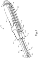
- FIGS. 6 and 7 show an exemplary linear surgical stapler (200) (or “linear cutter") that is generally similar to linear surgical stapler (10) described above except as otherwise described below.
- Linear surgical stapler (200) includes a cartridge half (202) (or “reload half') and an anvil half (204) configured to releasably couple together to clamp tissue therebetween for simultaneous cutting and stapling of the clamped tissue.
- Cartridge half (202) includes an elongate cartridge channel (206) having a proximal frame portion (208) and distal jaw portion (210).
- Proximal frame portion (208) includes a laterally opposed pair of upright side flanges (212), each having a vertical slot (214) arranged at a distal end thereof, and a tapered notch (216) arranged at a proximal end thereof.
- An outwardly projecting stiffening rib (218) extends longitudinally between distal slot (214) and the proximal notch (216) of each side flange (212) and is configured to provide the side flange (212) with enhanced stiffness.
- An outwardly flared upper segment (220) defines an upper edge of a proximal portion of each side flange (212) and is configured to facilitate receipt of anvil half (204) by cartridge half (202), described in greater detail below.
- Each side flange (212) of cartridge half (202) further includes an elongate firing slot (222) extending longitudinally between proximal notch (216) and distal slot (214) along a lower side of side flange (212).
- Elongate firing slots (222) are configured to guide a firing assembly (224) slidably retained within proximal frame portion (208) between proximal and distal positions.
- Firing assembly (224) includes, among other features, a slider block (226) and a pair of actuators (228) (or “firing knobs”) pivotably coupled with slider block (226) to provide dual-sided firing of stapler (10).
- Firing assembly (224) may be further configured in accordance with the teachings of U.S. Pat. App. No. [Atty Dkt. END8623USNP], entitled “Firing System for Linear Surgical Stapler,” filed on even date herewith, the disclosure of which is incorporated by reference herein.
- Distal jaw portion (210) of cartridge channel (206) is configured to receive a staple cartridge (230) (or "reload"), which may be similar to staple cartridge (80) described above except as otherwise described below.
- Staple cartridge (230) includes a cartridge body (232) that houses a plurality of staple drivers and staples (not shown) similar to staple drivers (86) and staples (88).
- Cartridge body (232) further includes a longitudinal slot (234) configured to slidably receive a knife member (not shown) of firing assembly (224), and a pair of interior slots (not shown) configured to slidably receive a pair of cam ramps (not shown) of firing assembly (224).
- staple cartridge (230) and firing assembly (224) may be alternatively configured such that the knife member and cam ramps are housed within cartridge body (232), similar to staple cartridge (80).
- Staple cartridge (230) of the present version further includes a pair of proximal coupling legs (236) configured to be directed through an opening (not shown) in a base wall of cartridge channel (206) and releasably coupled to a clamp lever pivot pin (242) with a snap-fit engagement.
- Cartridge half (202) further includes a clamp lever (240) pivotably coupled to cartridge channel (206) with clamp lever pivot pin (242), which is arranged in approximate alignment with distal slots (214) of cartridge channel side flanges (212).
- Clamp lever (240) includes an elongate lever arm (244) having a free proximal end (245) and a distal end that is pivotably coupled to a lower portion of cartridge channel (206) with pivot pin (242).
- a pair of opposed jaws (246) extend distally from the distal end of lever arm (244) alongside cartridge channel side flanges (212).
- Each jaw (246) includes a curved slot (248) having a closed proximal end and an open distal end configured to receive a distal coupling member (278) of anvil half (204), as described below.
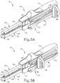
- Clamp lever (240) is operable to pivot relative to cartridge channel (206) between an open position (see FIG. 11A ) in which proximal end (245) of lever arm (244) is spaced from cartridge channel frame portion (208), and a closed position (see FIG. 11B ) in which proximal end (245) confronts cartridge channel frame portion (208).
- Actuation of clamp lever (240) from the open position to the closed position operates to clamp anvil half (204) against cartridge half (202).
- the curvature of each jaw slot (248) defines respective upper and lower camming surfaces configured to engage and draw the distal coupling member (278) of anvil half (204) toward cartridge channel (206) as clamp lever (240) is pivotably closed, as described in greater detail below.
- cartridge half (202) further includes a clamp lever latch member (250) arranged at proximal end (245) of lever arm (244).
- clamp lever latch member (250) is resiliently biased to engage a proximal end of cartridge channel (206) and thereby releasably retain clamp lever (240) in the closed position, for instance while stapler (200) is being fired.
- a resilient member shown in the form of a flat spring (252) biases clamp lever (240) toward the open position. Accordingly, flat spring (252) promotes disengagement of lever jaws (246) from anvil half (204) upon disengagement of clamp lever latch member (250) from the proximal end of cartridge channel (206), as described below.
- Cartridge half (202) further includes a retaining assembly (260) arranged at a proximal end thereof.
- retaining assembly (260) includes an anvil latch member (262) and a detent member (264) rotatably coupled to a proximal end of cartridge channel (206).
- Anvil latch member (262) and detent member (264) are configured to rotate independently of one another about a shared rotational axis.
- Anvil latch member (262) is configured to releasably capture a proximal pin (280) of anvil half (204) and thereby pivotably couple a proximal end of cartridge half (202) with a proximal end of anvil half (204). As shown in FIG.
- anvil latch member (262) includes a lower release button (266) that is exposed through an underside of cartridge channel (206) when clamp lever (240) is opened, and which is concealed when clamp lever (240) is closed.
- Release button (266) is configured to be depressed by an operator to selectively disengage anvil latch member (262) from proximal anvil pin (280) and thereby permit separation of the proximal ends of stapler halves (202, 204).
- Detent member (264) of retaining assembly (260) is configured to releasably retain firing assembly (224) in a proximal home position. As shown in FIGS.
- detent member (264) includes a proximal hook (268) configured to maintain clamp lever (240) in the closed position while firing assembly (224) is translated distally from its proximal home position, as described below.
- Retaining assembly (260) may be further configured and operable in accordance with the teachings of U.S. Pat. App. No. [Atty Dkt. END8623USNP], incorporated by reference above.
- anvil half (204) of linear surgical stapler (200) includes an elongate anvil channel (270) having a proximal frame portion (272) and a distal jaw portion (274).
- Proximal frame portion (272) includes a laterally opposed pair of side flanges (276) that are configured to be received between cartridge channel side flanges (212) when anvil half (204) is coupled with cartridge half (202).
- a distal coupling member in the form of a distal anvil pin (278) extends laterally through the distal ends of anvil channel side flanges (276), and a proximal coupling member in the form of a proximal anvil pin (280) extends laterally through the proximal ends of anvil channel side flanges (276).
- Anvil pins (278, 280) are configured to facilitate coupling of anvil half (204) with cartridge half (202) as described below.
- Distal jaw portion (274) of anvil half (204) supports an anvil surface (282) having a plurality of staple forming pockets (not shown) configured to deform the legs of staples ejected by staple cartridge (230) when stapler (200) is fired.
- anvil surface (282) may be formed integrally with or otherwise be rigidly connected to distal jaw portion (274).
- anvil surface (282) maybe adjustable relative to distal jaw portion (274) in a manner similar to anvil plate (60) of stapler (10) described above.
- Distal jaw portion (274) of anvil half (204) additionally supports a tapered distal tip member (284).
- linear surgical stapler (200) includes a plurality of shrouds (254, 300) that cover select portions of stapler (200) and promote effective grip and manipulation of stapler (200) by an operator during use.
- a clamp lever shroud (254) is affixed to and covers an outwardly facing side of clamp lever (240) such that clamp lever shroud (254) is configured to pivot with clamp lever (240) relative to cartridge channel (206).
- an anvil shroud (300) is affixed to and covers an outwardly facing side of anvil channel (270). Exemplary methods of securing anvil shroud (300) to anvil channel (270) are described below.
- proximal anvil pin (280) of anvil half (204) is directed into proximal tapered notches (216) of cartridge channel (206).
- clamp lever (240) is held in the open position by resilient member (252) such that the open distal ends of curved jaw slots (248) align with the open upper ends of cartridge channel distal slots (214).
- Anvil half (204) is then pivoted about proximal anvil pin (280) to direct distal anvil pin (278) into vertical distal slots (214) of cartridge channel (206) and curved jaw slots (248) of clamp lever (240).
- Clamp lever (240) is then pivoted from the open position to the closed position, which causes the upper and lower camming surfaces of curved jaw slots (248) to engage and draw distal anvil pin (278) toward the closed proximal ends of curved jaw slots (248). This action draws distal jaw portion (274) of anvil channel (270) closer toward distal jaw portion (210) of cartridge channel (206), thereby clamping any tissue positioned between anvil surface (282) and staple cartridge (230).
- clamp lever latch member (250) engages the proximal end of cartridge channel (206) to maintain clamp lever (240) in the closed position.
- Stapler (200) may then be fired by actuating firing assembly (224) distally, similar to firing assembly (34).
- firing assembly (224) is returned to its proximal home position, and clamp lever latch member (250) is disengaged from cartridge channel (206) to enable opening of clamp lever (240) and subsequent separation of stapler halves (202, 204).
- FIGS. 8-10C show additional details of components of anvil half (204), and corresponding steps of assembling such components.
- anvil channel side flanges (276) include a pair of distal openings (286) configured to receive distal anvil pin (278) laterally therethrough, and a pair of proximal openings (288) configured to receive proximal anvil pin (280) laterally therethrough.
- a base wall of proximal frame portion (272) includes an elongate distal slot (290) arranged approximately in alignment with distal openings (286), and a proximal slot (292) arranged longitudinally between distal openings (286) and proximal openings (288).
- Proximal and distal slots (290, 292) are positioned along a longitudinal centerline of anvil channel (270).
- Anvil shroud (300), shown in partial cross-section in FIG. 8 includes an inner flange (302) extending longitudinally within an interior of anvil shroud (300), parallel to the longitudinal centerline of anvil channel (270), and projecting transversely in a direction toward anvil channel (270).
- Inner flange (302) includes a foot-shaped distal tab (304) extending transversely toward anvil channel (270) and having a distal nose (306) that extends distally beyond a distal end (308) of a base portion of inner flange (302).
- Distal tab (304) includes a keyhole slot (310) having a circular entry portion (312) and an elongate retaining portion (314) extending proximally from circular entry portion (312).
- keyhole slot (310) is oriented parallel to a longitudinal axis of anvil channel (270).
- Inner flange (302) further includes a rectangular proximal tab (316) extending transversely toward anvil channel (270).
- Distal slot (290) of anvil channel (270) is configured to receive distal tab (304) of anvil shroud (300), and proximal slot (292) is configured to receive proximal tab (316).
- anvil channel slots (290, 292) are suitably sized such that the respective tab (304, 316) is slidable longitudinally therein.
- Anvil shroud (300) further includes a pair of proximal openings (318) extending laterally through a proximal end of anvil shroud (300), and are configured to receive proximal anvil pin (280) therethrough as described below.
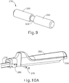
- distal anvil pin (278) of the present version is in the form of a stepped pin having a pair of cylindrical shoulders (320) and a cylindrical neck (322) arranged medially therebetween.
- Pin neck (322) is formed with a smaller outer diameter than pin shoulders (320) such that pin shoulders (320) define a maximum outer diameter of distal anvil pin (278) and pin neck (322) defines a minimum outer diameter of distal anvil pin (278).
- proximal pin (280) of the present example is cylindrical with a non-stepped configuration.
- FIG. 10A depicts components of anvil half (204) during an initial stage of assembly, showing anvil shroud (300) having been lowered onto anvil channel (270) such that distal tab (304) of anvil shroud (300) is received through distal slot (290) of anvil channel (270) and proximal tab (316) is received through proximal slot (292).
- anvil shroud tabs (304, 316) are positioned proximally within slots (290, 292) such that circular entry portion (312) of keyhole slot (310) aligns longitudinally with distal openings (286) of anvil channel (270).
- Stepped distal anvil pin (278) is then inserted laterally through distal openings (286) and circular entry portion (312), such that narrowed neck (322) of distal anvil pin (278) resides within keyhole slot (310).
- anvil shroud (300) is then translated distally relative to anvil channel (270) such that anvil shroud tabs (304, 316) slide distally within their respective anvil channel slots (290, 292), and such that proximal shroud openings (318) are brought into alignment with proximal anvil channel openings (288).
- Proximal anvil pin (280) is then inserted laterally through aligned proximal openings (288, 318), thereby fixing anvil shroud (300) longitudinally relative to anvil channel (270), and fixing the proximal end of anvil shroud (300) transversely relative to anvil channel (270).
- Proximal shroud openings (318) may be sized to receive proximal anvil pin (280) with an interference fit, thereby securing proximal pin (280) laterally relative to anvil shroud (300) and anvil channel (270) once inserted.
- anvil shroud (300) The distal translation of anvil shroud (300) relative to anvil channel (270) shown in FIG. 10C also operates to position distal nose (306) of distal shroud tab (304) distally of a distal end of distal anvil channel slot (290), thereby securing the distal end of anvil shroud (300) transversely relative to anvil channel (270). Additionally, narrowed neck (322) of distal anvil pin (278) is received within elongate retaining portion (314) of keyhole slot (310) of anvil shroud (300).
- Each pin shoulder (320) is formed with an outer diameter that is slightly larger than the diameter of elongate retaining portion (314) such that distal anvil pin (278) is constrained laterally relative to anvil shroud (300) and anvil channel (270). Furthermore, distal openings (286) of anvil channel (270) are sized slightly larger than pin shoulders (320), and elongate retaining portion (314) of keyhole slot (310) is sized slightly larger than pin neck (322), such that distal anvil pin (278) is configured to rotate relative to anvil channel (270) and anvil shroud (300) with a slip fit engagement even though constrained laterally.
- anvil half (204) is mounted to cartridge half (202) in the manner generally described above, such that proximal anvil pin (280) is received within proximal tapered notches (216) (see FIG. 7 ) of cartridge channel (206).
- a medial portion of proximal anvil pin (280) is captured by anvil latch member (262) (see FIG. 12 ) of proximal retaining assembly (260) of cartridge half (202), thereby pivotably coupling the proximal end of anvil half (204) with the proximal end of cartridge half (202).
- Anvil half (204) is then pivoted about proximal anvil pin (280) to direct pin shoulders (320) of distal anvil pin (278) into distal vertical slots (214) of cartridge channel (206) (see FIG. 7 ) and curved slots (248) of clamp lever jaws (246).
- Clamp lever (240) is then pivoted from the open position to the closed position so that the upper and lower camming surfaces of jaw slots (248) engage distal pin shoulders (320).
- distal anvil pin (278) rotates relative to anvil channel (270) and anvil shroud (300), and thereby rolls along the camming surfaces of jaw slots (248).
- distal anvil pin (278) rotates in a counter-clockwise direction when clamp lever (240) is closed, and in a clockwise direction when clamp lever (240) is opened.
- this rotation of distal anvil pin (278) helps to minimize friction between clamp lever jaws (246) and distal anvil pin (278) when clamp lever (240) is closed and opened, and consequently minimize the forces that an operator must exert on clamp lever (240) to transition stapler (200) between unclamped and clamped states.
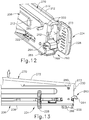
- FIGS. 12 and 13 show details of an exemplary pair of hinge stops (330) rigidly coupled with a proximal end of cartridge channel (206).
- hinge stops (330) are in the form of tabs integrally formed with the upper proximal ends of cartridge channel side flanges (212), and have free ends that wrap inwardly to define a proximal-most end of cartridge channel (206).
- hinge stops (330) are configured to abut a proximal face (273) of proximal frame portion (272) of anvil channel (270) to limit the degree to which anvil half (204) may pivotably open relative to cartridge half (202).
- Hinge stops (330) may be suitably configured to permit any desired degree of pivoting of anvil half (204) relative to cartridge half (202) so as to permit a corresponding maximum aperture distance between the distal ends of anvil half (204) and cartridge half (202).
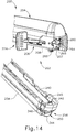
- FIGS. 14-16D show additional details and functionality of clamp lever latch member (250) of linear surgical stapler (200).
- clamp lever latch member (250) is configured to releasably couple free proximal end (245) of clamp lever (240) to proximal frame portion (208) of cartridge channel (206), and thereby releasably maintain clamp lever (240) in the closed position.
- clamp lever latch member (250) includes an upwardly extending finger (340) having a distally facing cam surface (342), a downwardly extending release button (344), and a pair of distally extending stop arms (346).
- Clamp lever latch member (250) is pivotably coupled to proximal end (245) of clamp lever (240) with a laterally extending pin (348) such that upper finger (340) extends transversely toward cartridge channel (206) and lower release button (344) extends transversely away from cartridge channel (206).
- a proximal end of clamp lever shroud (254) wraps around clamp lever latch member (250) and includes an opening (256) that exposes lower release button (344) for access by an operator.
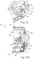
- Clamp lever latch member (250) is configured to rotate relative to lever arm (244) about pivot pin (348).
- a resilient member shown in the form of a torsion spring (350) biases latch member (250) rotationally such that distal stop arms (346) rest against an inner base surface of lever arm (244).
- latch member (250) is configured to rotate against the bias of torsion spring (350) when distal cam surface (342) contacts a proximal ledge (207) of cartridge channel (206) during closure of clamp lever (240).
- FIG. 16B when clamp lever (240) reaches a fully closed position, upper finger (340) of clamp lever latch member (250) hooks over proximal ledge (207), thereby maintaining clamp lever (240) in the closed position.
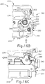
- slider block (226) disengages detent member (264) of proximal retaining assembly (260).
- This disengagement enables detent member (264) to rotate clockwise (in the left-side view shown in FIG. 16C ) under rotational bias such that proximal hook (268) of detent member (264) latches over the tip of upper finger (340) of clamp lever latch member (250).
- This engagement of detent member (264) with clamp lever latch member (250) prevents latch member (250) from being rotated via release button (344) to disengage latch member (250) from cartridge channel (206).
- clamp lever (240) is locked in the closed position while firing assembly (224) is translated distally from its proximal home position during a firing stroke.
- firing assembly (224) is translated distally from its proximal home position during a firing stroke.
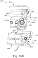
- return of slider block (226) of firing assembly (224) to its proximal home position rotates detent member (264) and its hook (268) away from clamp lever latch member (250). Consequently, lower release button (344) may be depressed by an operator to disengage clamp lever latch member (250) from cartridge channel (206) and then open clamp lever (240).
- clamp lever latch member (250) is configured such that its latch feature (340) and its release feature (344) are both arranged at the proximal end of clamp lever (240).
- Such a configuration may enable an operator to more easily release the latch mechanism and open clamp lever (240) with a single hand.
- FIG. 17 and 18 show an exemplary cartridge half (360) of a linear surgical stapler that includes a clamp lever latch mechanism (380) having a configuration of the type described above.
- Cartridge half (360) and/or one or more of its components are suitable for use with the complementary portions of linear surgical stapler (200) described above.
- Cartridge half (360) is similar to cartridge half (202) of stapler (200) except as otherwise described below.
- cartridge half (360) includes an elongate cartridge channel (362), a clamp lever (364) pivotably coupled with cartridge channel (362) and having a lever arm (366) and a pair of lever jaws (368), and a clamp lever shroud (370) coupled to lever arm (366) and having a distal shoulder (372).
- cartridge half (360) further includes a clamp lever latch mechanism (380) that is received within clamp lever shroud (370) and about an exterior of clamp lever (364).
- Latch mechanism (380) of the present example includes a translating structure (382) having a central body (384), a latch finger (386) rigidly coupled to and extending proximally from central body (384), and a pair of actuator arms (388) rigidly coupled to and extending distally from central body (384).
- Each actuator arm (388) includes a distal actuator knob (390).
- Clamp lever latch mechanism (380) further includes a resilient member shown in the form of a compression spring (392).
- Spring (392) is constrained at a proximal end by an anchor element (374) rigidly coupled with a base surface of clamp lever shroud (370), and at a distal end by a spring basket (394) of central body (384).
- translating structure (382) is configured to translate relative to clamp lever (364) and clamp lever shroud (370) between proximal and distal positions
- compression spring (392) is configured to bias translating structure (382) distally.
- Clamp lever (364), clamp lever shroud (370), and clamp lever latch mechanism (380) are configured to be assembled such that latch mechanism (380) is slidably received within an interior of shroud (370).
- Actuator arms (388) are configured to flex laterally relative to central body (384) to facilitate assembly.
- Each actuator knob (390) is exposed through a distal opening (376) formed in a respective lateral side of shroud shoulder (372), and proximal latch finger (386) is exposed through a proximal opening (378) formed in a proximal end of shroud (370).
- Latch mechanism (380) and shroud (370) are then mounted to clamp lever arm (366) such that shroud (370) is fixed relative to lever arm (366) while translating structure (382) of latch mechanism (380) remains longitudinally translatable relative to clamp lever (364) and shroud (370).
- translating structure (382) of clamp lever latch mechanism (380) is configured to translate between a distal home position ( FIG. 19A ), and a proximal extended position ( FIG. 19B ).
- Compression spring (392) biases translating structure (382) toward the distal home position.
- a proximal cam surface (387) of latch finger (386) engages the proximal end of a base wall (363) of cartridge channel (362) and drives translating structure (382) proximally through proximal opening (378) of shroud (370).
- translating structure (382) Upon clamp lever (364) reaching a fully closed position, translating structure (382) automatically returns to its distal home position via compression spring (392) so that proximal latch finger (386) hooks over and captures a proximal end of cartridge channel base wall (363), thereby releasably securing clamp lever (364) in the closed position.
- an operator actuates knobs (390) proximally, which in turn drives latch finger (386) proximally via actuator arms (388) and central body (384).
- anvil latch member (262) of proximal retaining assembly (260) of cartridge half (202) is configured to releasably capture proximal anvil pin (280) of anvil half (204) to couple the proximal ends of stapler halves (202, 204) together, even while clamp lever (240) remains in a fully open position.
- Release button (266) of retaining assembly (260) may then be actuated by an operator to disengage anvil latch member (262) from proximal anvil pin (280) and permit manual separation of stapler halves (202, 204) by the operator.
- anvil latch member of a linear surgical stapler such that the release feature not only enables separation of the proximal ends of the stapler halves, but furthermore drives automatic separation of the proximal ends.
- the exemplary alternative anvil latch member (408) described below incorporates features that provide such functionality.
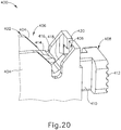
- FIG. 20 shows the proximal end of an exemplary cartridge half (400) that is similar to cartridge half (202) described above except as otherwise described below.
- Cartridge half (400) includes, among other components not shown, an elongate cartridge channel (402) having a proximal frame portion that includes a pair of upright side flanges (404).
- a pair of tapered notches (406) are formed in the proximal ends of upright side flanges (404) and are configured to receive a proximal pin (422) (see FIGS. 21A-21D ) of an anvil half (not shown), which may be similar to anvil half (204) described above.
- Cartridge half (400) further includes an anvil latch member (408) moveably coupled to a proximal end of cartridge channel (402).
- anvil latch member (408) is configured to releasably couple the proximal end of cartridge half (400) with the proximal end of an anvil half (not shown).
- Anvil latch member (408) of the present example includes a tab-like latch body (410), a transversely oriented release button (412) arranged at a proximal end of latch body (410), and a proximally facing latch finger (414) arranged at a distal end of latch body (410).
- An upper face of distal latch finger (414) defines a loading cam surface (416) that slopes proximally, and a distal face of latch body (410) defines an unloading cam surface (418) that slopes distally such that cam surfaces (416, 418) are sloped toward one another.
- Latch body (410) is configured to translate longitudinally through a slot (420) formed in the proximal end of cartridge channel (402), and a resilient member (not shown) is configured to bias anvil latch member (408) proximally.
- Slot (420) may be sized slightly larger than latch body (410) in a vertical direction to enable anvil latch member (408) to both translate and pivot relative to cartridge channel (402), as shown in FIGS. 21A-21C .
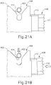
- FIGS. 21A-21C show exemplary coupling and decoupling of the proximal end of an anvil half (not shown) having a proximal pin (422), with the proximal end of cartridge half (400).
- the proximal end of the anvil half is aligned with the proximal end of cartridge half (400) so as to direct proximal anvil pin (422) into channel notches (406) and into engagement with loading cam surface (416) of latch finger (414).
- this engagement drives anvil latch member (408) distally against the bias of its resilient member (not shown), until anvil pin (422) is captured by latch finger (414) as shown in FIG. 21C .
- release button (412) of anvil latch member (408) is depressed distally by an operator as shown in FIG. 21D .
- This actuation causes anvil latch member (408) to simultaneously translate and pivot distally such that unloading cam surface (418) drives anvil pin (422) upwardly and ejects pin (422) from proximal notches (406) of cartridge channel (402).
- the proximal end of the anvil half is automatically separated from the proximal end of cartridge half (400) upon actuation of release button (412), without requiring the operator to manually pull the stapler halves apart to release anvil pin (422) from cartridge channel (402).
- anvil shroud (300) includes features that facilitate assembly of the components of anvil half (204) and permit distal anvil pin (278) to freely rotate during clamping of stapler halves (202, 204).
- FIGS. 22A-26F show additional exemplary anvil halves (430, 500, 530) suitable for use with cartridge half (202) and having exemplary alternative features configured to permit rotation of a distal anvil pin during clamping of the stapler halves.
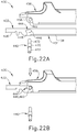
- FIGS. 22A-24B show an exemplary anvil half (430) that is similar to anvil half (204) described above except as otherwise described below.
- Anvil half (430) includes, among other components, an elongate anvil channel (432) having a proximal frame portion (434) and a distal jaw portion (436).
- Proximal frame portion (434) includes a laterally opposed pair of upright side flanges (438) that are configured to be received between the side flanges of a cartridge half, such as cartridge half (202) described above, when anvil half (430) is coupled with the cartridge half.
- Anvil half (430) further includes a distal coupling member in the form of a laterally extending distal pin (440), and a proximal coupling member in the form of a laterally extending proximal pin (442) (see FIG. 24A ).
- anvil pins (440, 442) are configured to secure an anvil shroud (456) to anvil channel (432), in addition to being configured to facilitate coupling of anvil half (430) with a cartridge half in the manner described above in connection with stapler (200).
- anvil channel (432) further includes a pair of keyhole slots (444) that are oriented longitudinally on the distal ends of side flanges (438) and are configured to receive distal anvil pin (440) laterally therethrough with a slip fit.
- Each keyhole slot (444) includes a circular entry portion (446) oriented proximally and an elongate retaining portion (448) oriented distally, such that keyhole slots (444) extend parallel to a longitudinal axis of anvil channel (432).
- Anvil channel (432) further includes a pair of proximal openings (450) (see FIG. 24A ) that are arranged at the proximal ends of side flanges (438) and are configured to receive proximal anvil pin (442) laterally therethrough.
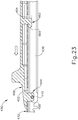
- anvil shroud (456) includes a distal inner tab (458) and a proximal inner tab (460) (see FIG. 23 ) extending transversely toward anvil channel (432) along a longitudinal centerline of anvil shroud (456).
- Distal inner tab (458) includes a circular opening (462) configured to receive distal anvil pin (440) laterally therethrough with a slip fit.
- Proximal inner tab (460) is generally foot-shaped and has a distally extending tip (464).
- Tabs (458, 460) of anvil shroud (456) are configured to be received through and translate longitudinally within respective elongate slots (452, 454) formed in abase wall of anvil channel (432) (see FIG. 23 ).
- anvil shroud (456) further includes a pair of proximal projections (466) extending inwardly from the proximal ends of opposed inner walls of anvil shroud (456).
- distal anvil pin (440) is in the form of a stepped pin having a medial shoulder (470) and a pair of cylindrical shafts (472) extending outwardly from either end of shoulder (470).
- Pin shoulder (470) is formed with a larger outer diameter than pin shafts (472) such that pin shoulder (470) defines a maximum outer diameter of distal anvil pin (440) and pin shafts (472) each define a minimum outer diameter of distal anvil pin (440).
- proximal anvil pin (442) of the present example is cylindrical with a non-stepped configuration.
- FIGS. 22A and 22B depict the components of anvil half (430) during an initial stage of assembly in which anvil shroud (456) is lowered onto anvil channel (432) such that distal inner tab (458) of anvil shroud (456) is received through distal anvil channel slot (452) and proximal inner tab (460) is received through proximal anvil channel slot (454).
- Anvil shroud (456) is positioned proximally relative to anvil channel (432) such that circular entry portions (446) of keyhole slots (444) on anvil channel (432) align with circular opening (462) on distal inner tab (458) of anvil shroud (456).
- Distal anvil pin (440) is then inserted laterally through circular entry portions (446) and circular opening (462) such that pin shoulder (470) resides within circular opening (462).
- the insertion of distal anvil pin (440) operates to secure the distal end of anvil shroud (456) transversely relative to anvil channel (432).
- proximal anvil pin (442) is inserted laterally through proximal openings (450) of anvil channel (432) prior to mounting anvil shroud (456) to anvil channel (432).
- anvil shroud (456) and distal anvil pin (440) are then translated distally relative to anvil channel (432) such that pin shafts (472) are received within elongate retaining portions (448) of keyhole slots (444) on anvil channel (432).
- Pin shoulder (470) is sized larger than elongate retaining portions (448) such that distal anvil pin (440) becomes constrained laterally relative to anvil channel (432) and anvil shroud (456) as a result of the distal translation of anvil shroud (456) and distal anvil pin (440), as shown in FIG. 22D .
- FIG. 22D As shown in FIG.
- anvil shroud (456) operates to advance additional features of anvil shroud (456) relative to anvil channel (432).
- distal tip (464) of proximal inner tab (460) is advanced distally beyond a distal end of proximal anvil channel slot (454), thus securing the proximal end of anvil shroud (456) transversely relative to anvil channel (432).
- proximal inner projections (466) of anvil shroud (456) are advanced distally over and beyond the lateral ends of proximal anvil pin (442) in a detent-like engagement, thereby securing anvil shroud (456) longitudinally relative to anvil channel (432).
- anvil half (430) is fully assembled such that distal anvil pin (440) is constrained laterally while still being permitted to rotate relative to anvil channel (432) and anvil shroud (456).
- distal anvil pin (440) provides friction-reducing advantages when clamping of anvil half (430) against a corresponding cartridge half of a linear surgical stapler.
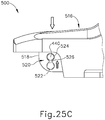
- FIGS. 25A-25C show another exemplary anvil half (500) that is similar to anvil halves (204, 430) described above except as otherwise described below.
- Anvil half (500) includes, among other components, an elongate anvil channel (502) having a proximal frame portion (504) and a distal jaw portion (506).
- Proximal frame portion (504) includes a laterally opposed pair of upright side flanges (508) that are configured to be received between side flanges of a cartridge half, such as cartridge half (202) described above, when anvil half (500) is coupled with the cartridge half.
- Anvil half (500) further includes a distal coupling member in the form of stepped distal anvil pin (440), described above.
- anvil half (500) further includes a proximal coupling member in the form of a laterally extending proximal pin, which may be similar to proximal anvil pins (280, 442) described above.
- Distal anvil pin (440) and the proximal anvil pin are configured to secure an anvil shroud (516) to anvil channel (502), in addition to being configured to facilitate coupling of anvil half (500) with a cartridge half in the manner described above in connection with stapler (200).
- anvil channel (502) further includes a pair of keyhole slots (510) that are oriented transversely on the distal ends of side flanges (508) and are configured to receive distal anvil pin (440) laterally therethrough with a slip fit.
- Each keyhole slot (510) includes a circular entry portion (512) oriented toward a base wall of anvil channel (502), and an elongate retaining portion (514) oriented toward a free edge of the respective side flange (508).
- Anvil channel (502) further includes a pair of proximal openings (not shown), similar to proximal openings (288, 450), that are arranged at the proximal ends of side flanges (508) and are configured to receive the proximal anvil pin (not shown) laterally therethrough.
- anvil shroud (516) includes a distal inner tab (518) extending transversely toward anvil channel (502) and having a detented slot (520).
- Detented slot (520) includes a generally circular entry portion (522) and a generally circular retaining portion (524) separated from one another by a pair of detent bumps (526). Entry portion (522) and retaining portion (524) are each similar in size and are configured to receive distal anvil pin (440) therethrough with a slip fit. Entry and retaining portions (522, 524) cooperate to define a centerline of detented slot (520) that is oriented transversely to a longitudinal axis of anvil half (500). Accordingly, detented slot (520) and keyhole slots (510) of the present example are oriented parallel to one another, and transversely to a longitudinal axis of anvil half (500).
- FIG. 25A depicts the components of anvil half (500) in an initial stage of assembly in which anvil shroud (516) is lowered onto anvil channel (502) such that entry portion (522) of detented slot (520) aligns with entry portions (512) of keyhole slots (510).
- Distal anvil pin (440) is then inserted laterally through entry portions (512, 522), as shown in FIG. 25A , and anvil shroud (516) is then lowered further relative to anvil channel (502) to seat pin shafts (472) within retaining portions (514) of keyhole slots (510). Consequently, distal anvil pin (440) is now constrained laterally relative to anvil channel (502) and anvil shroud (516), and anvil shroud (516) is secured longitudinally relative to anvil channel (502).
- anvil shroud (516) is pressed further transversely toward anvil channel (502).
- Distal anvil pin (440) resists further movement in this direction as a result of being seated within retaining portions (514) of keyhole slots (510). Accordingly, anvil shroud (516) advances transversely relative to distal anvil pin (440) such that pin shoulder (470) passes from entry portion (522) of detented slot (520), over detent bumps (526), and into retaining portion (524) of detented slot (520), as shown in FIG. 25C .
- Detent bumps (526) thus secure the proximal end of anvil shroud (516) transversely relative to anvil channel (502) while still permitting distal anvil pin (440) to freely rotate relative to anvil shroud (516) and anvil channel (502).
- the proximal end of anvil shroud (516) may be secured to anvil channel (502) with a proximal anvil pin (not shown) in a manner similar to that described above in connection with anvil half (204).
- anvil half (500) is fully assembled such that distal anvil pin (440) is constrained laterally while still being permitted to rotate relative to anvil channel (502) and anvil shroud (516).
- distal anvil pin (440) provides friction-reducing advantages when clamping of anvil half (500) against a corresponding cartridge half of a linear surgical stapler.
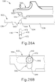
- FIGS. 26A-26F show another exemplary anvil half (530) that is similar to anvil halves (204, 430, 500) described above except as otherwise described below.
- Anvil half (530) includes, among other components, an elongate anvil channel (532) having a proximal frame portion (534) and a distal jaw portion (536).
- Proximal frame portion (534) includes a laterally opposed pair of upright side flanges (538) that are configured to be received between the side flanges of a cartridge half, such as cartridge half (202) described above, when anvil half (530) is coupled with the cartridge half.
- Anvil half (530) further includes a distal coupling member in the form of stepped distal anvil pin (440) described above, and a proximal coupling member in the form of cylindrical proximal anvil pin (442) described above.
- Anvil pins (440, 442) are configured to secure an anvil shroud (550) to anvil channel (432), in addition to being configured to facilitate coupling of anvil half (530) with a cartridge half in the manner described above in connection with stapler (200).
- anvil channel (532) further includes a pair of keyhole slots (540) that are oriented transversely on the distal ends of side flanges (538) and are configured to receive distal anvil pin (440) laterally therethrough with a slip fit.
- Each keyhole slot (540) includes a circular entry portion (542) oriented toward a base wall of anvil channel (532), and an elongate retaining portion (544) oriented toward a free edge of the respective side flange (538).
- Anvil channel (532) further includes a pair of proximal openings (not shown), similar to proximal openings (288, 450) that are arranged at the proximal ends of side flanges (538) and are configured to receive proximal anvil pin (442) laterally therethrough.
- a base wall of anvil channel (532) includes a distal slot (not shown), similar to distal slot (290), configured to slidably receive a distal inner tab (552) of anvil shroud (550) therethrough, and a proximal slot (546) (see FIG. 26E ) configured to slidably receive a proximal inner tab (556) of anvil shroud (550) therethrough.
- distal inner tab (552) of anvil shroud (550) extends transversely toward anvil channel (532) and has a longitudinal slot (554) configured to receive distal anvil pin (440) laterally therethrough with a slip fit.
- proximal inner tab (556) of anvil shroud (550) extends transversely toward anvil channel (532) and has a circular opening (558).
- anvil shroud (550) further includes a pair of proximal openings (560) extending laterally through opposed sidewalls of anvil shroud (550).
- proximal openings (560) are formed with hexagonal shapes.
- Circular opening (558) of proximal inner tab (556) and proximal openings (560) of the shroud sidewalls are aligned with one another and are configured to receive proximal anvil pin (442) laterally therethrough with an interference fit.
- FIGS. 26A and 26B depict the components of anvil half (530) in an initial stage of assembly in which anvil shroud (550) is lowered onto anvil channel (532) such that distal inner tab (552) is received through the distal slot (not shown) of anvil channel (532).
- Anvil shroud (550) is initially positioned such that longitudinal slot (554) of distal inner tab (552) is aligned with circular entry portions (542) of keyhole slots (540) of anvil channel (532).
- Distal anvil pin (440) is then inserted laterally through circular entry portions (542) and longitudinal slot (554), as shown in FIG. 26B .
- FIG. 26B depict the components of anvil half (530) in an initial stage of assembly in which anvil shroud (550) is lowered onto anvil channel (532) such that distal inner tab (552) is received through the distal slot (not shown) of anvil channel (532).
- Anvil shroud (550) is initially positioned such that longitudinal slot (554) of
- anvil shroud (550) is lowered further to seat pin shafts (472) within lower retaining portions (544) of keyhole slots (540), thereby constraining distal anvil pin (440) laterally relative to anvil channel (532) and anvil shroud (550).
- anvil shroud (550) is then translated proximally relative to anvil channel (532) to align opening (558) of proximal inner tab (556) and proximal openings (560) of the sidewalls of shroud (550) with the proximal openings (not shown) of anvil channel (532).
- proximal anvil pin (442) is then inserted laterally through the anvil and shroud openings (558, 560), thereby securing anvil shroud (550) longitudinally and transversely relative to anvil channel (532).
- anvil half (530) is fully assembled such that distal anvil pin (440) is constrained laterally while still being permitted to rotate relative to anvil channel (532) and anvil shroud (550).
- distal anvil pin (440) provides friction-reducing advantages when clamping of anvil half (530) against a corresponding cartridge half of a linear surgical stapler.
- clamp lever latch member (250) and proximal hook (268) of retaining assembly (260) are configured to releasably lock clamp lever (240) in the closed position.
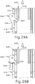
- 27-29C includes such a clamp lever lockout member (640), which is operable to prevent closure of clamp lever (618) until stapler halves (602, 604) are properly aligned to ensure that distal anvil pin (636) is effectively captured by clamp lever jaws (622).
- a clamp lever lockout member 640
- Linear surgical stapler (600) is generally similar to linear surgical stapler (200) described above except as otherwise described below. Moreover, any one or more features of stapler (600), such as lockout member (640), may be implemented with stapler (200) or any of other exemplary stapler halves disclosed herein. Similar to stapler (200), stapler (600) includes a cartridge half (602) and an anvil half (604) configured to releasably couple together to clamp tissue therebetween.
- Cartridge half (602) includes an elongate cartridge channel (606) having a proximal frame portion (608) configured to slidably house a firing assembly (not shown), which may be similar to firing assembly (224), and a distal jaw portion (610) configured to receive a staple cartridge (not shown), which may be similar to staple cartridge (230).
- Proximal frame portion (608) includes a laterally opposed pair of upright side flanges (612), a pair of vertical slots (614) arranged in the distal ends of side flanges (612), and a pair of tapered notches (616) arranged in the proximal ends of side flanges (612).
- Cartridge half (602) further includes a clamp lever (618) pivotably coupled to proximal frame portion (608).
- Clamp lever (618) includes an elongate lever arm (620) and a pair of laterally opposed jaws (622) extending distally from a distal end of elongate lever arm (620).
- Each jaw (622) includes a curved jaw slot (624) defining upper and lower camming surfaces.
- Anvil half (604) of linear surgical stapler (600) includes an elongate anvil channel (630) having a proximal frame portion (632) and a distal jaw portion (634) that supports an anvil surface (not shown) configured to deform staples ejected by the staple cartridge (not shown).
- Anvil half (604) further includes a distal coupling member in the form of a laterally extending distal pin (636), and a proximal coupling member in the form of a laterally extending proximal pin (638).
- stapler (600) may further include a plurality of shrouds, such as a clamp lever shroud and an anvil shroud similar to clamp lever shroud (254) and anvil shroud (300) described above, for example.
- Cartridge half (602) of stapler (600) further includes a clamp lever lockout member (640) pivotably coupled to a distal end of a cartridge channel side flange (612) via outwardly projecting support tabs (642) arranged proximally of vertical slots (614).
- Clamp lever lockout member (640) is configured to pivot about a horizontal axis, which extends parallel to a longitudinal axis of cartridge channel (606), to prevent closure of clamp lever (618) until stapler halves (602, 604) are properly aligned with one another, as described in greater detail below.
- clamp lever lockout member (640) includes an outer arm (644) that extends along an exterior of cartridge channel side flange (612), and an inner arm (646) that is angled relative to outer arm (644) and extends into an interior of cartridge channel (606). As shown in FIGS. 27 and 29A , outer arm (644) is configured to engage a jaw shoulder (626) of clamp lever (618) and hold clamp lever (618) in the fully open position such that the open distal ends of jaw slots (624) remain aligned with vertical slots (614) of cartridge channel (606).
- Inner arm (646) of lockout member (640) is configured to be engaged by proximal frame portion (632) of anvil channel (630) when anvil half (604) is initially received by cartridge half (602). Specifically, as shown in FIGS. 29A and 29B , engagement of anvil proximal frame portion (632) with inner arm (646) causes lockout member (640) to pivot outwardly such that outer arm (644) disengages jaw shoulder (626) and permits clamp lever (618) to be closed, as shown in FIG. 29C .
- clamp lever lockout member (640) ensures that clamp lever (618) may be closed only once distal anvil pin (636) of anvil half (604) has been received by vertical slots (614) of cartridge channel (606) and jaw slots (624) of clamp lever (618), thereby preventing premature closure of clamp lever (618).
- lockout member (640) Upon return of clamp lever (618) to the fully open position, lockout member (640) automatically returns to its lockout position to reengage jaw shoulder (626) in the manner described above.
- FIGS. 30-32 show another exemplary linear surgical stapler (700) having a cartridge half (702) and an anvil half (704) that are substantially similar to stapler halves (202, 204) described above, as indicated by use of like reference numerals in FIGS. 30-32 , except as otherwise described below.
- stapler halves (702, 704) are resiliently biased away from one another to provide assisted separation of halves (702, 704) and enhanced one-handed usability of stapler (700), as described in greater detail below.
- Anvil half (704) of linear surgical stapler (700) includes a resilient member shown in the form of a compression spring (706) housed within the interior of a distal shoulder (324) of anvil shroud (300).
- the interior of shoulder (324) includes a post (708) that projects inwardly toward proximal frame portion (272) of anvil channel (270).
- An outer end (710) of spring (706) encircles post (708) and is thereby constrained relative to anvil shroud (300), and a free inner end (712) of spring (706) extends transversely toward proximal frame portion (272) of anvil channel (270).
- a compression spring 706 housed within the interior of a distal shoulder (324) of anvil shroud (300).
- the interior of shoulder (324) includes a post (708) that projects inwardly toward proximal frame portion (272) of anvil channel (270).
- An outer end (710) of spring (706) encircles post (708) and
- inner spring end (712) is configured to confront an outer surface of the base wall of anvil channel (270) when spring (706) is in a relaxed stated.
- Post (708) may be formed integrally with anvil shroud (300) or otherwise rigidly connected to shroud (300). In some versions, post (708) may be omitted and outer spring end (710) may be secured directly to anvil shroud (300).
- compression spring (706) may be substituted with various alternative types of resilient members readily apparent to those of ordinary skill in the art in view of the teachings herein, such as a leaf spring or a wave spring, for example.
- inner end (712) of compression spring (706) defines a spring width that is greater than a width of proximal frame portion (272) of anvil channel (270), and greater than or equal to a width of proximal frame portion (208) of cartridge channel (206).
- inner spring end (712) flares outwardly relative to outer spring end (710), though in other versions spring (706) may be formed with a constant outer diameter.
- inner spring end (712) is configured to directly contact the upper surfaces of cartridge channel side flanges (212) when anvil half (704) is clamped against cartridge half (702) by closing clamp lever (240) in the manner described above in connection with stapler (200). Consequently, as shown in FIG. 31A , cartridge channel side flanges (212) compress inner spring end (712) toward outer spring end (710) when stapler halves (702, 704) are fully clamped together by clamp lever (240).
- compression spring (706) decompresses and drives against cartridge channel side flanges (212) to push cartridge channel (206) away from anvil channel (270).
- spring (706) urges stapler halves (702, 704) to pivot open about proximal anvil pin (280) such that a distal aperture (714) is formed between the distal portions of stapler halves (702, 704). Because stapler halves (702, 704) remain coupled together at their proximal ends via anvil latch member (262) (see FIGS. 16A-16D ), the operator is enabled to easily remove tissue from staple halves (702, 704) while holding stapler (700) with a single hand.
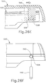
- FIG. 32 shows an exemplary alternative cartridge half (720) suitable for use with anvil half (704) of linear surgical stapler (700).
- Cartridge half (720) is similar to cartridge halves (202, 702) described above except as otherwise described below. Similar to cartridge halves (202, 702), cartridge half (720) includes an elongate cartridge channel (722) having a proximal frame portion with upright side flanges (724), and a clamp lever (730) pivotably coupled with cartridge channel (722). Cartridge half (720) further includes a pair of protrusions shown in the form of raised tabs (726) extending upwardly from distal portions of cartridge channel side flanges (724).
- Tabs (726) may be formed integrally with side flanges (724), or otherwise be rigidly coupled to side flanges (724). The upper end of each tab (726) is configured to engage a respective side of inner end (712) of compression spring (706) of anvil half (704) in a manner similar to side flanges (212) of cartridge channel (206). Each tab (726) is formed with a transverse height (H) above the upper edge of the respective cartridge channel side flange (724). Tab heights (H) may be selected to compress spring (706) by a predetermined amount when anvil half (704) is clamped against cartridge half (720), and thereby tune the resulting spring force exerted by compression spring (706) on cartridge channel (722). It will be appreciated that the selected tab heights (H) will also dictate a size of the resulting aperture defined between the distal ends of stapler halves (704, 720) when clamp lever (730) is opened, for example as seen in FIG. 31C .
- each jaw (246) of clamp lever (240) includes a curved slot (248) that defines first and second camming structures arranged on opposing sides of curved slot (248).
- the first (or proximal) camming structure defines a first camming surface configured to draw distal anvil pin (278) into jaw slot (248) and the respective cartridge channel distal slot (214) when clamp lever (240) is closed.
- the second (or distal) camming structure defines a second camming surface configured to eject distal anvil pin (278) from jaw slot (248) and the respective cartridge channel distal slot (214) when clamp lever (240) is opened.
- Clamp lever (730) of cartridge half (720) differs from clamp lever (240) in that clamp lever (720) includes a pair of jaws (732) each having a single camming structure.
- the single camming structure defines a curved distal camming surface (734) configured to draw in distal anvil pin (278) for clamping an anvil half (204, 704) against cartridge half (720).
- This configuration of jaws (732), in which second camming structures are omitted reduces the risk of a "friction-locking" scenario in which clamp lever (730) becomes stuck in the closed position, particularly when clamping tissues of greater thicknesses.
- jaws (732) are configured to enhance the spring-assisted separation of stapler halves (704, 720) provided by compression spring (706).
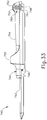
- FIG. 33 shows an exemplary alternative anvil half (740) configured in such a manner as described below, and which is suitable for use with any of the exemplary cartridge halves (202, 702, 720) described above.
- Anvil half (740) is similar to anvil halves (204, 704) in that anvil half (740) includes an elongate anvil channel (742) and an anvil shroud (744) secured to a proximal frame portion of anvil channel (742) with a distal anvil pin (746) and a proximal anvil pin (748).
- Anvil shroud (744) is similar to anvil shroud (300) described above except as otherwise described below. Like anvil shroud (300), anvil shroud (744) includes a distal shoulder (750) arranged at a distal end of shroud (744). However, anvil shroud (744) further includes a proximal grip feature shown in the form of a second shoulder (752) arranged at a proximal end of shroud (744). Proximal shoulder (752) of the present example protrudes outwardly relative to a medial portion (754) of anvil shroud (744) and has a hollow interior similar to distal shoulder (750).
- medial shroud portion (754) is configured to be gripped by the operator such that proximal shoulder (752) constrains the operator's hand proximally, for instance during distal firing of firing assembly (224), and distal shoulder (750) constrains the operator's hand distally, for instance during proximal retraction of firing assembly (224).
- Anvil half (740) further includes a resilient member shown schematically in the form of a compression spring (760) that is similar in structure and function to compression spring (706) of anvil half (704) described above.
- compression spring (760) is housed within the open interior of proximal shoulder (752) of anvil shroud (744) at a location just distally of proximal anvil pin (748).
- Compression spring (760) includes an outer end (762) that is fixed relative to anvil shroud (744), and a free inner end (764) that extends toward and confronts a proximal end of anvil channel (742).
- Inner spring end (764) is configured to directly contact and provide for resilient compression of spring (760) against upper surfaces of the proximal ends of cartridge channel side flanges (212, 724) when anvil half (740) is clamped against cartridge half (202, 702, 720). Accordingly, similar to compression spring (706) described above, compression spring (760) is configured to provide spring-assisted opening of anvil half (740) relative to a cartridge half (202, 702, 720) when clamp lever (240, 730) is opened.
- raised tabs (726) of cartridge half (720) may be located proximally to interact with compression spring (760) of anvil half (740). Additionally, in some versions compression spring (760) may be housed within distal shoulder (750) of anvil shroud (744), similar to compression spring (760). In other versions, resilient members such as compression springs (706, 760) may be housed within both distal shoulder (750) and proximal shoulder (752).
- a surgical stapler comprising: (a) a first elongate member having a distal portion that supports an anvil surface, wherein the anvil surface includes a plurality of staple forming pockets; (b) a second elongate member having a distal portion configured to receive a staple cartridge; (c) a pin rotatably coupled with the first elongate member; and (d) a clamp member movably coupled with the second elongate member, wherein the clamp member is operable to releasably capture the pin to thereby clamp the first elongate member against the second elongate member, wherein the pin is configured to rotate relative to the first elongate member in response to being captured by the clamp member.
- the pin includes a first cylindrical end portion, a second cylindrical end portion, and a medial portion extending therebetween, when the medial portion has a different outer diameter than the first cylindrical end portion and the second cylindrical end portion.
- the surgical stapler of any of the preceding Examples further comprising a shroud configured to cover at least a portion of the first elongate member, wherein the pin couples the shroud with the first elongate member.
- the surgical stapler of Examples 4 through 6 further comprising a keyhole slot arranged on one of the shroud or the first elongate member, wherein the pin extends through the keyhole slot.
- Example 7 The surgical stapler of Example 7, wherein the keyhole slot is configured to constrain the pin laterally relative to the shroud and the first elongate member.
- clamp member is moveable from an unclamped position to a clamped position to clamp the first elongate member against the second elongate member, wherein the clamp member includes a latching feature configured to releasably retain the clamp member in the clamped position.
- Example 13 The surgical stapler of Example 13, wherein the clamp member comprises a lever, wherein the latching feature comprises a latch member pivotably coupled to a free end of the lever.
- the surgical stapler of any of the preceding Examples further comprising a latch member movably coupled to a proximal end of the second elongate member, wherein the latch member is operable to releasably couple the proximal end of the second elongate member with a proximal end of the first elongate member.
- a surgical stapler comprising: (a) a first stapler half comprising: (i) an elongate member having a distal portion that supports an anvil surface, wherein the anvil surface includes a plurality of staple forming pockets, (ii) a shroud, (iii) a keyhole slot arranged in one of the elongate member or the shroud, and (iv) a coupling member, wherein the coupling member extends through the keyhole slot and couples the shroud with the elongate member; and (b) a second stapler half comprising: (i) a distal portion configured to support a staple cartridge, and (ii) a clamp member operable to releasably capture the coupling member to thereby clamp the first stapler half against the second stapler half.
- the coupling member comprises a pin
- the keyhole slot is configured to constrain the pin laterally relative to the elongate member and the shroud.
- a surgical stapler comprising: A surgical stapler comprising: (a) a first elongate member having a distal portion that supports an anvil surface, wherein the anvil surface includes a plurality of staple forming pockets; (b) a second elongate member having a distal portion configured to receive a staple cartridge; (c) a clamp lever operable to pivot from a first position to a second position to clamp the first elongate member against the second elongate member; and (d) a latch member coupled to the clamp lever, wherein the latch member is operable to releasably couple a free end of the clamp lever with the second elongate member when the clamp lever is in the second position.
- a surgical stapler comprising: (a) a first elongate member having a distal portion that supports an anvil surface, wherein the anvil surface includes a plurality of staple forming pockets; (b) a second elongate member having a distal portion configured to receive a staple cartridge; (c) a clamp member, wherein the clamp member is moveable from a first position to a second position to releasably clamp the first elongate member against the second elongate member; and (d) a resilient member, wherein the resilient member is configured to urge the distal portion of the first elongate member away from the distal portion of the second elongate member when the clamp member is in the first position.
- the surgical stapler of Example 21 further comprising a shroud that covers at least a portion of the first elongate member, wherein the resilient member is housed at least partially within the shroud.
- the shroud includes a shoulder that projects away from the first elongate member, wherein the resilient member is housed at least partially within an interior of the shoulder.
- an interior of the shroud includes a post, wherein the resilient member is coupled to the post.
- Example 27 The surgical stapler of Example 27, wherein the second elongate member includes at least one protrusion that extends toward the first elongate member, wherein the resilient member is configured to resiliently contact the at least one protrusion.
- Example 28 The surgical stapler of Example 28, wherein the at least one protrusion comprises a pair of tabs.
- a proximal end of the first elongate member is configured to releasably couple with a proximal end of the second elongate member
- the resilient member is configured to urge the distal portion of the first elongate member away from the distal portion of the second elongate member while the proximal ends of the first and second elongate members remain coupled together.
- any one or more of the teachings, expressions, embodiments, examples, etc. described herein may be combined with any one or more of the teachings, expressions, embodiments, examples, etc. described in U.S. App. No. 15/889,363 , entitled “Release Mechanism for Linear Surgical Stapler,” filed on February 6, 2018; U.S. App. No. 15/889,370 , entitled “Lockout Assembly for Linear Surgical Stapler,” filed on February 6, 2018; U.S. App. No. 15/889,374 , entitled “Features to Align and Close Linear Surgical Stapler”,” filed on February 6, 2018; U.S. App. No.
- Versions of the devices described above may be designed to be disposed of after a single use, or they can be designed to be used multiple times. Versions may, in either or both cases, be reconditioned for reuse after at least one use. Reconditioning may include any combination of the steps of disassembly of the device, followed by cleaning or replacement of particular pieces, and subsequent reassembly. In particular, some versions of the device may be disassembled, and any number of the particular pieces or parts of the device may be selectively replaced or removed in any combination. Upon cleaning and/or replacement of particular parts, some versions of the device may be reassembled for subsequent use either at a reconditioning facility, or by a user immediately prior to a procedure.
- reconditioning of a device may utilize a variety of techniques for disassembly, cleaning/replacement, and reassembly. Use of such techniques, and the resulting reconditioned device, are all within the scope of the present application.
- versions described herein may be sterilized before and/or after a procedure.
- the device is placed in a closed and sealed container, such as a plastic or TYVEK bag.
- the container and device may then be placed in a field of radiation that can penetrate the container, such as gamma radiation, x-rays, or high-energy electrons.
- the radiation may kill bacteria on the device and in the container.
- the sterilized device may then be stored in the sterile container for later use.
- a device may also be sterilized using any other technique known in the art, including but not limited to beta or gamma radiation, ethylene oxide, or steam.
Landscapes
- Health & Medical Sciences (AREA)
- Life Sciences & Earth Sciences (AREA)
- Surgery (AREA)
- Heart & Thoracic Surgery (AREA)
- Engineering & Computer Science (AREA)
- Biomedical Technology (AREA)
- Nuclear Medicine, Radiotherapy & Molecular Imaging (AREA)
- Medical Informatics (AREA)
- Molecular Biology (AREA)
- Animal Behavior & Ethology (AREA)
- General Health & Medical Sciences (AREA)
- Public Health (AREA)
- Veterinary Medicine (AREA)
- Surgical Instruments (AREA)
Applications Claiming Priority (1)
| Application Number | Priority Date | Filing Date | Title |
|---|---|---|---|
| US16/102,170 US11278285B2 (en) | 2018-08-13 | 2018-08-13 | Clamping assembly for linear surgical stapler |
Publications (2)
| Publication Number | Publication Date |
|---|---|
| EP3610801A2 true EP3610801A2 (fr) | 2020-02-19 |
| EP3610801A3 EP3610801A3 (fr) | 2020-04-01 |
Family
ID=67614510
Family Applications (1)
| Application Number | Title | Priority Date | Filing Date |
|---|---|---|---|
| EP19191305.2A Pending EP3610801A3 (fr) | 2018-08-13 | 2019-08-12 | Ensemble de serrage pour agrafeuse chirurgicale linéaire |
Country Status (6)
| Country | Link |
|---|---|
| US (2) | US11278285B2 (fr) |
| EP (1) | EP3610801A3 (fr) |
| JP (2) | JP7367000B2 (fr) |
| BR (1) | BR112021002623A2 (fr) |
| MX (1) | MX2021001782A (fr) |
| WO (1) | WO2020035763A2 (fr) |
Cited By (1)
| Publication number | Priority date | Publication date | Assignee | Title |
|---|---|---|---|---|
| WO2023242702A1 (fr) * | 2022-06-14 | 2023-12-21 | Cilag Gmbh International | Agrafeuse chirurgicale linéaire |
Families Citing this family (123)
| Publication number | Priority date | Publication date | Assignee | Title |
|---|---|---|---|---|
| US11871901B2 (en) | 2012-05-20 | 2024-01-16 | Cilag Gmbh International | Method for situational awareness for surgical network or surgical network connected device capable of adjusting function based on a sensed situation or usage |
| US11504192B2 (en) | 2014-10-30 | 2022-11-22 | Cilag Gmbh International | Method of hub communication with surgical instrument systems |
| US10709448B2 (en) * | 2017-06-05 | 2020-07-14 | Grena Usa Llc | Linear cutter stapler |
| US11291510B2 (en) | 2017-10-30 | 2022-04-05 | Cilag Gmbh International | Method of hub communication with surgical instrument systems |
| US11071560B2 (en) | 2017-10-30 | 2021-07-27 | Cilag Gmbh International | Surgical clip applier comprising adaptive control in response to a strain gauge circuit |
| US11510741B2 (en) | 2017-10-30 | 2022-11-29 | Cilag Gmbh International | Method for producing a surgical instrument comprising a smart electrical system |
| US11311342B2 (en) | 2017-10-30 | 2022-04-26 | Cilag Gmbh International | Method for communicating with surgical instrument systems |
| US11911045B2 (en) | 2017-10-30 | 2024-02-27 | Cllag GmbH International | Method for operating a powered articulating multi-clip applier |
| US11801098B2 (en) | 2017-10-30 | 2023-10-31 | Cilag Gmbh International | Method of hub communication with surgical instrument systems |
| US11045197B2 (en) | 2017-10-30 | 2021-06-29 | Cilag Gmbh International | Clip applier comprising a movable clip magazine |
| US11564756B2 (en) | 2017-10-30 | 2023-01-31 | Cilag Gmbh International | Method of hub communication with surgical instrument systems |
| US11229436B2 (en) | 2017-10-30 | 2022-01-25 | Cilag Gmbh International | Surgical system comprising a surgical tool and a surgical hub |
| US11317919B2 (en) | 2017-10-30 | 2022-05-03 | Cilag Gmbh International | Clip applier comprising a clip crimping system |
| US11304720B2 (en) | 2017-12-28 | 2022-04-19 | Cilag Gmbh International | Activation of energy devices |
| US11678881B2 (en) | 2017-12-28 | 2023-06-20 | Cilag Gmbh International | Spatial awareness of surgical hubs in operating rooms |
| US11659023B2 (en) | 2017-12-28 | 2023-05-23 | Cilag Gmbh International | Method of hub communication |
| US11696760B2 (en) | 2017-12-28 | 2023-07-11 | Cilag Gmbh International | Safety systems for smart powered surgical stapling |
| US11278281B2 (en) | 2017-12-28 | 2022-03-22 | Cilag Gmbh International | Interactive surgical system |
| US11832899B2 (en) | 2017-12-28 | 2023-12-05 | Cilag Gmbh International | Surgical systems with autonomously adjustable control programs |
| US11234756B2 (en) | 2017-12-28 | 2022-02-01 | Cilag Gmbh International | Powered surgical tool with predefined adjustable control algorithm for controlling end effector parameter |
| US11424027B2 (en) | 2017-12-28 | 2022-08-23 | Cilag Gmbh International | Method for operating surgical instrument systems |
| US11284936B2 (en) | 2017-12-28 | 2022-03-29 | Cilag Gmbh International | Surgical instrument having a flexible electrode |
| US11202570B2 (en) | 2017-12-28 | 2021-12-21 | Cilag Gmbh International | Communication hub and storage device for storing parameters and status of a surgical device to be shared with cloud based analytics systems |
| US11179208B2 (en) | 2017-12-28 | 2021-11-23 | Cilag Gmbh International | Cloud-based medical analytics for security and authentication trends and reactive measures |
| US11857152B2 (en) | 2017-12-28 | 2024-01-02 | Cilag Gmbh International | Surgical hub spatial awareness to determine devices in operating theater |
| US11423007B2 (en) | 2017-12-28 | 2022-08-23 | Cilag Gmbh International | Adjustment of device control programs based on stratified contextual data in addition to the data |
| US20190201039A1 (en) | 2017-12-28 | 2019-07-04 | Ethicon Llc | Situational awareness of electrosurgical systems |
| US11832840B2 (en) | 2017-12-28 | 2023-12-05 | Cilag Gmbh International | Surgical instrument having a flexible circuit |
| US11324557B2 (en) | 2017-12-28 | 2022-05-10 | Cilag Gmbh International | Surgical instrument with a sensing array |
| US11253315B2 (en) | 2017-12-28 | 2022-02-22 | Cilag Gmbh International | Increasing radio frequency to create pad-less monopolar loop |
| US11589888B2 (en) | 2017-12-28 | 2023-02-28 | Cilag Gmbh International | Method for controlling smart energy devices |
| US11410259B2 (en) | 2017-12-28 | 2022-08-09 | Cilag Gmbh International | Adaptive control program updates for surgical devices |
| US11896443B2 (en) | 2017-12-28 | 2024-02-13 | Cilag Gmbh International | Control of a surgical system through a surgical barrier |
| US11559308B2 (en) | 2017-12-28 | 2023-01-24 | Cilag Gmbh International | Method for smart energy device infrastructure |
| US11432885B2 (en) | 2017-12-28 | 2022-09-06 | Cilag Gmbh International | Sensing arrangements for robot-assisted surgical platforms |
| US11576677B2 (en) | 2017-12-28 | 2023-02-14 | Cilag Gmbh International | Method of hub communication, processing, display, and cloud analytics |
| US11213359B2 (en) | 2017-12-28 | 2022-01-04 | Cilag Gmbh International | Controllers for robot-assisted surgical platforms |
| US11389164B2 (en) | 2017-12-28 | 2022-07-19 | Cilag Gmbh International | Method of using reinforced flexible circuits with multiple sensors to optimize performance of radio frequency devices |
| US11364075B2 (en) | 2017-12-28 | 2022-06-21 | Cilag Gmbh International | Radio frequency energy device for delivering combined electrical signals |
| US11308075B2 (en) | 2017-12-28 | 2022-04-19 | Cilag Gmbh International | Surgical network, instrument, and cloud responses based on validation of received dataset and authentication of its source and integrity |
| US11937769B2 (en) | 2017-12-28 | 2024-03-26 | Cilag Gmbh International | Method of hub communication, processing, storage and display |
| US11744604B2 (en) | 2017-12-28 | 2023-09-05 | Cilag Gmbh International | Surgical instrument with a hardware-only control circuit |
| US11969216B2 (en) | 2017-12-28 | 2024-04-30 | Cilag Gmbh International | Surgical network recommendations from real time analysis of procedure variables against a baseline highlighting differences from the optimal solution |
| US11786245B2 (en) | 2017-12-28 | 2023-10-17 | Cilag Gmbh International | Surgical systems with prioritized data transmission capabilities |
| US11376002B2 (en) | 2017-12-28 | 2022-07-05 | Cilag Gmbh International | Surgical instrument cartridge sensor assemblies |
| US10892995B2 (en) | 2017-12-28 | 2021-01-12 | Ethicon Llc | Surgical network determination of prioritization of communication, interaction, or processing based on system or device needs |
| US11559307B2 (en) | 2017-12-28 | 2023-01-24 | Cilag Gmbh International | Method of robotic hub communication, detection, and control |
| US11273001B2 (en) | 2017-12-28 | 2022-03-15 | Cilag Gmbh International | Surgical hub and modular device response adjustment based on situational awareness |
| US11612444B2 (en) | 2017-12-28 | 2023-03-28 | Cilag Gmbh International | Adjustment of a surgical device function based on situational awareness |
| US11602393B2 (en) | 2017-12-28 | 2023-03-14 | Cilag Gmbh International | Surgical evacuation sensing and generator control |
| US11132462B2 (en) | 2017-12-28 | 2021-09-28 | Cilag Gmbh International | Data stripping method to interrogate patient records and create anonymized record |
| US11026751B2 (en) | 2017-12-28 | 2021-06-08 | Cilag Gmbh International | Display of alignment of staple cartridge to prior linear staple line |
| US11419667B2 (en) | 2017-12-28 | 2022-08-23 | Cilag Gmbh International | Ultrasonic energy device which varies pressure applied by clamp arm to provide threshold control pressure at a cut progression location |
| US11317937B2 (en) | 2018-03-08 | 2022-05-03 | Cilag Gmbh International | Determining the state of an ultrasonic end effector |
| US11896322B2 (en) | 2017-12-28 | 2024-02-13 | Cilag Gmbh International | Sensing the patient position and contact utilizing the mono-polar return pad electrode to provide situational awareness to the hub |
| US10758310B2 (en) | 2017-12-28 | 2020-09-01 | Ethicon Llc | Wireless pairing of a surgical device with another device within a sterile surgical field based on the usage and situational awareness of devices |
| US11464535B2 (en) | 2017-12-28 | 2022-10-11 | Cilag Gmbh International | Detection of end effector emersion in liquid |
| US11446052B2 (en) | 2017-12-28 | 2022-09-20 | Cilag Gmbh International | Variation of radio frequency and ultrasonic power level in cooperation with varying clamp arm pressure to achieve predefined heat flux or power applied to tissue |
| US11633237B2 (en) | 2017-12-28 | 2023-04-25 | Cilag Gmbh International | Usage and technique analysis of surgeon / staff performance against a baseline to optimize device utilization and performance for both current and future procedures |
| US11464559B2 (en) | 2017-12-28 | 2022-10-11 | Cilag Gmbh International | Estimating state of ultrasonic end effector and control system therefor |
| US11529187B2 (en) | 2017-12-28 | 2022-12-20 | Cilag Gmbh International | Surgical evacuation sensor arrangements |
| US11612408B2 (en) | 2017-12-28 | 2023-03-28 | Cilag Gmbh International | Determining tissue composition via an ultrasonic system |
| US11257589B2 (en) | 2017-12-28 | 2022-02-22 | Cilag Gmbh International | Real-time analysis of comprehensive cost of all instrumentation used in surgery utilizing data fluidity to track instruments through stocking and in-house processes |
| US11109866B2 (en) | 2017-12-28 | 2021-09-07 | Cilag Gmbh International | Method for circular stapler control algorithm adjustment based on situational awareness |
| US11311306B2 (en) | 2017-12-28 | 2022-04-26 | Cilag Gmbh International | Surgical systems for detecting end effector tissue distribution irregularities |
| US11903601B2 (en) | 2017-12-28 | 2024-02-20 | Cilag Gmbh International | Surgical instrument comprising a plurality of drive systems |
| US11160605B2 (en) | 2017-12-28 | 2021-11-02 | Cilag Gmbh International | Surgical evacuation sensing and motor control |
| US11291495B2 (en) | 2017-12-28 | 2022-04-05 | Cilag Gmbh International | Interruption of energy due to inadvertent capacitive coupling |
| US11304745B2 (en) | 2017-12-28 | 2022-04-19 | Cilag Gmbh International | Surgical evacuation sensing and display |
| US11266468B2 (en) | 2017-12-28 | 2022-03-08 | Cilag Gmbh International | Cooperative utilization of data derived from secondary sources by intelligent surgical hubs |
| US11969142B2 (en) | 2017-12-28 | 2024-04-30 | Cilag Gmbh International | Method of compressing tissue within a stapling device and simultaneously displaying the location of the tissue within the jaws |
| US11540855B2 (en) | 2017-12-28 | 2023-01-03 | Cilag Gmbh International | Controlling activation of an ultrasonic surgical instrument according to the presence of tissue |
| US11864728B2 (en) | 2017-12-28 | 2024-01-09 | Cilag Gmbh International | Characterization of tissue irregularities through the use of mono-chromatic light refractivity |
| US11786251B2 (en) | 2017-12-28 | 2023-10-17 | Cilag Gmbh International | Method for adaptive control schemes for surgical network control and interaction |
| US11013563B2 (en) | 2017-12-28 | 2021-05-25 | Ethicon Llc | Drive arrangements for robot-assisted surgical platforms |
| US11419630B2 (en) | 2017-12-28 | 2022-08-23 | Cilag Gmbh International | Surgical system distributed processing |
| US11166772B2 (en) | 2017-12-28 | 2021-11-09 | Cilag Gmbh International | Surgical hub coordination of control and communication of operating room devices |
| US11304763B2 (en) | 2017-12-28 | 2022-04-19 | Cilag Gmbh International | Image capturing of the areas outside the abdomen to improve placement and control of a surgical device in use |
| US11666331B2 (en) | 2017-12-28 | 2023-06-06 | Cilag Gmbh International | Systems for detecting proximity of surgical end effector to cancerous tissue |
| US11304699B2 (en) | 2017-12-28 | 2022-04-19 | Cilag Gmbh International | Method for adaptive control schemes for surgical network control and interaction |
| US11571234B2 (en) | 2017-12-28 | 2023-02-07 | Cilag Gmbh International | Temperature control of ultrasonic end effector and control system therefor |
| US11818052B2 (en) | 2017-12-28 | 2023-11-14 | Cilag Gmbh International | Surgical network determination of prioritization of communication, interaction, or processing based on system or device needs |
| US10932781B2 (en) * | 2018-02-06 | 2021-03-02 | Ethicon Llc | Features to align and close linear surgical stapler |
| US10631866B2 (en) * | 2018-02-06 | 2020-04-28 | Ethicon Llc | Release mechanism for linear surgical stapler |
| US11589915B2 (en) | 2018-03-08 | 2023-02-28 | Cilag Gmbh International | In-the-jaw classifier based on a model |
| US11707293B2 (en) | 2018-03-08 | 2023-07-25 | Cilag Gmbh International | Ultrasonic sealing algorithm with temperature control |
| US11259830B2 (en) | 2018-03-08 | 2022-03-01 | Cilag Gmbh International | Methods for controlling temperature in ultrasonic device |
| US11207067B2 (en) | 2018-03-28 | 2021-12-28 | Cilag Gmbh International | Surgical stapling device with separate rotary driven closure and firing systems and firing member that engages both jaws while firing |
| US11197668B2 (en) | 2018-03-28 | 2021-12-14 | Cilag Gmbh International | Surgical stapling assembly comprising a lockout and an exterior access orifice to permit artificial unlocking of the lockout |
| US11219453B2 (en) | 2018-03-28 | 2022-01-11 | Cilag Gmbh International | Surgical stapling devices with cartridge compatible closure and firing lockout arrangements |
| US11259806B2 (en) | 2018-03-28 | 2022-03-01 | Cilag Gmbh International | Surgical stapling devices with features for blocking advancement of a camming assembly of an incompatible cartridge installed therein |
| US11471156B2 (en) | 2018-03-28 | 2022-10-18 | Cilag Gmbh International | Surgical stapling devices with improved rotary driven closure systems |
| US11090047B2 (en) | 2018-03-28 | 2021-08-17 | Cilag Gmbh International | Surgical instrument comprising an adaptive control system |
| US11278280B2 (en) | 2018-03-28 | 2022-03-22 | Cilag Gmbh International | Surgical instrument comprising a jaw closure lockout |
| USD913495S1 (en) * | 2018-08-13 | 2021-03-16 | Ethicon Llc | Linear surgical stapler |
| US10898187B2 (en) | 2018-08-13 | 2021-01-26 | Ethicon Llc | Firing system for linear surgical stapler |
| US10905419B2 (en) | 2018-10-11 | 2021-02-02 | Ethicon Llc | Closure assembly for linear surgical stapler |
| US11751872B2 (en) * | 2019-02-19 | 2023-09-12 | Cilag Gmbh International | Insertable deactivator element for surgical stapler lockouts |
| US11357503B2 (en) | 2019-02-19 | 2022-06-14 | Cilag Gmbh International | Staple cartridge retainers with frangible retention features and methods of using same |
| US11317915B2 (en) | 2019-02-19 | 2022-05-03 | Cilag Gmbh International | Universal cartridge based key feature that unlocks multiple lockout arrangements in different surgical staplers |
| US11291444B2 (en) | 2019-02-19 | 2022-04-05 | Cilag Gmbh International | Surgical stapling assembly with cartridge based retainer configured to unlock a closure lockout |
| US11369377B2 (en) | 2019-02-19 | 2022-06-28 | Cilag Gmbh International | Surgical stapling assembly with cartridge based retainer configured to unlock a firing lockout |
| USD928319S1 (en) * | 2019-05-01 | 2021-08-17 | Cilag Gmbh International | Linear surgical stapler |
| USD950728S1 (en) | 2019-06-25 | 2022-05-03 | Cilag Gmbh International | Surgical staple cartridge |
| USD952144S1 (en) | 2019-06-25 | 2022-05-17 | Cilag Gmbh International | Surgical staple cartridge retainer with firing system authentication key |
| USD964564S1 (en) | 2019-06-25 | 2022-09-20 | Cilag Gmbh International | Surgical staple cartridge retainer with a closure system authentication key |
| US11420313B2 (en) * | 2019-07-08 | 2022-08-23 | Apex Mfg. Co., Ltd. | Staple gun |
| WO2021016436A1 (fr) * | 2019-07-24 | 2021-01-28 | Boston Scientific Scimed, Inc. | Dispositif de fermeture |
| US11229433B2 (en) | 2019-08-09 | 2022-01-25 | Cilag Gmbh International | Linear surgical stapler |
| USD956230S1 (en) | 2019-08-09 | 2022-06-28 | Cilag Gmbh International | Staple cartridge assembly for linear surgical stapler |
| USD955575S1 (en) | 2019-08-09 | 2022-06-21 | Cilag Gmbh International | Staple cartridge assembly for linear surgical stapler |
| USD954949S1 (en) | 2019-08-09 | 2022-06-14 | Cilag Gmbh International | Retainer for surgical staple cartridge |
| US11219454B2 (en) | 2020-05-29 | 2022-01-11 | Cilag Gmbh International | Pin trap mechanism for surgical linear cutter |
| US11224425B2 (en) * | 2020-05-29 | 2022-01-18 | Cilag Gmbh International | Surgical linear cutter wishbone separation mechanism with detent |
| US11399827B2 (en) | 2020-05-29 | 2022-08-02 | Cilag Gmbh International | Separation mechanism for surgical linear cutter |
| US11553912B2 (en) | 2020-11-04 | 2023-01-17 | Cilag Gmbh International | Surgical stapler end effector sled having multiple surface finishes |
| US11540826B2 (en) | 2020-11-04 | 2023-01-03 | Cilag Gmbh International | Surgical stapler end effector sled having cartridge wall support feature |
| US11832814B2 (en) | 2020-11-04 | 2023-12-05 | Cilag Gmbh International | Surgical stapler end effector sled having tapered distal end |
| US11701112B2 (en) | 2020-11-04 | 2023-07-18 | Cilag Gmbh International | Surgical stapler end effector sled having staple driver support feature |
| US20220133316A1 (en) | 2020-11-04 | 2022-05-05 | Ethicon Llc | Surgical stapler end effector sled having cartridge biasing feature |
| US20220142641A1 (en) | 2020-11-10 | 2022-05-12 | Ethicon Llc | System and method for forming pockets in anvil of surgical stapler |
| US20230108568A1 (en) | 2021-09-27 | 2023-04-06 | Cilag Gmbh International | Staple and staple-forming pocket arrangements for surgical staplers |
| US11937812B2 (en) | 2021-09-30 | 2024-03-26 | Cilag Gmbh International | Lockout feature for linear surgical stapler cartridge |
Citations (22)
| Publication number | Priority date | Publication date | Assignee | Title |
|---|---|---|---|---|
| US5792135A (en) | 1996-05-20 | 1998-08-11 | Intuitive Surgical, Inc. | Articulated surgical instrument for performing minimally invasive surgery with enhanced dexterity and sensitivity |
| US5817084A (en) | 1993-05-14 | 1998-10-06 | Sri International | Remote center positioning device with flexible drive |
| US5878193A (en) | 1992-08-10 | 1999-03-02 | Computer Motion, Inc. | Automated endoscope system for optimal positioning |
| US6231565B1 (en) | 1997-06-18 | 2001-05-15 | United States Surgical Corporation | Robotic arm DLUs for performing surgical tasks |
| US6364888B1 (en) | 1996-09-09 | 2002-04-02 | Intuitive Surgical, Inc. | Alignment of master and slave in a minimally invasive surgical apparatus |
| US6783524B2 (en) | 2001-04-19 | 2004-08-31 | Intuitive Surgical, Inc. | Robotic surgical tool with ultrasound cauterizing and cutting instrument |
| US7524320B2 (en) | 1998-12-08 | 2009-04-28 | Intuitive Surgical, Inc. | Mechanical actuator interface system for robotic surgical tools |
| US7691098B2 (en) | 2001-06-29 | 2010-04-06 | Intuitive Surgical, Inc. | Platform link wrist mechanism |
| US7806891B2 (en) | 1998-11-20 | 2010-10-05 | Intuitive Surgical Operations, Inc. | Repositioning and reorientation of master/slave relationship in minimally invasive telesurgery |
| US7905381B2 (en) | 2008-09-19 | 2011-03-15 | Ethicon Endo-Surgery, Inc. | Surgical stapling instrument with cutting member arrangement |
| US8348129B2 (en) | 2009-10-09 | 2013-01-08 | Ethicon Endo-Surgery, Inc. | Surgical stapler having a closure mechanism |
| US8479969B2 (en) | 2007-01-10 | 2013-07-09 | Ethicon Endo-Surgery, Inc. | Drive interface for operably coupling a manipulatable surgical tool to a robot |
| US8573461B2 (en) | 2008-02-14 | 2013-11-05 | Ethicon Endo-Surgery, Inc. | Surgical stapling instruments with cam-driven staple deployment arrangements |
| US8573465B2 (en) | 2008-02-14 | 2013-11-05 | Ethicon Endo-Surgery, Inc. | Robotically-controlled surgical end effector system with rotary actuated closure systems |
| US8602288B2 (en) | 2008-09-23 | 2013-12-10 | Ethicon Endo-Surgery. Inc. | Robotically-controlled motorized surgical end effector system with rotary actuated closure systems having variable actuation speeds |
| US8616431B2 (en) | 2007-06-04 | 2013-12-31 | Ethicon Endo-Surgery, Inc. | Shiftable drive interface for robotically-controlled surgical tool |
| US8783541B2 (en) | 2003-05-20 | 2014-07-22 | Frederick E. Shelton, IV | Robotically-controlled surgical end effector system |
| US8789740B2 (en) | 2010-07-30 | 2014-07-29 | Ethicon Endo-Surgery, Inc. | Linear cutting and stapling device with selectively disengageable cutting member |
| US8800838B2 (en) | 2005-08-31 | 2014-08-12 | Ethicon Endo-Surgery, Inc. | Robotically-controlled cable-based surgical end effectors |
| US8820605B2 (en) | 2006-01-31 | 2014-09-02 | Ethicon Endo-Surgery, Inc. | Robotically-controlled surgical instruments |
| US8844789B2 (en) | 2006-01-31 | 2014-09-30 | Ethicon Endo-Surgery, Inc. | Automated end effector component reloading system for use with a robotic system |
| US9301759B2 (en) | 2006-03-23 | 2016-04-05 | Ethicon Endo-Surgery, Llc | Robotically-controlled surgical instrument with selectively articulatable end effector |
Family Cites Families (100)
| Publication number | Priority date | Publication date | Assignee | Title |
|---|---|---|---|---|
| US2066157A (en) * | 1933-01-28 | 1936-12-29 | William G Pankonin | Stapling machine |
| US2083227A (en) * | 1933-10-27 | 1937-06-08 | Lou Obstfeld | Stapling machine |
| US2311412A (en) * | 1940-07-01 | 1943-02-16 | William G Pankonin | Feed mechanism for stapling machines |
| US2469984A (en) * | 1945-04-30 | 1949-05-10 | William G Pankonin | Stapling device |
| US2946059A (en) * | 1956-03-29 | 1960-07-26 | Fastener Corp | Stapling apparatus |
| US2939146A (en) * | 1958-04-02 | 1960-06-07 | Arrow Fastener Co Inc | Table type hand operated stapler |
| US4047654A (en) * | 1976-06-23 | 1977-09-13 | Alfredo Alvarado | Surgical stapler |
| US4180196A (en) * | 1977-08-05 | 1979-12-25 | Senco Products, Inc. | Anvil attachment for a surgical stapling instrument |
| AU534210B2 (en) * | 1980-02-05 | 1984-01-12 | United States Surgical Corporation | Surgical staples |
| US4312363A (en) * | 1980-02-26 | 1982-01-26 | Senco Products, Inc. | Surgical tissue thickness measuring instrument |
| EP0061466A1 (fr) | 1980-09-18 | 1982-10-06 | Hospital Products Limited | Agrafeuse chirurgicale jetable |
| US4354628A (en) * | 1980-09-29 | 1982-10-19 | United States Surgical Corporation | Surgical stapler apparatus having pivotally related staple holder and anvil |
| US4453661A (en) * | 1980-10-23 | 1984-06-12 | Ivano-Frankovsky Gosudarstvenny Meditsinsky Institut | Surgical instrument for applying staples |
| US4522327A (en) * | 1983-05-18 | 1985-06-11 | United States Surgical Corporation | Surgical fastener applying apparatus |
| US4506819A (en) * | 1983-09-19 | 1985-03-26 | Rand Burt E | Staple supply indicator |
| US4580712A (en) * | 1984-10-19 | 1986-04-08 | United States Surgical Corporation | Surgical fastener applying apparatus with progressive application of fastener |
| US4608981A (en) | 1984-10-19 | 1986-09-02 | Senmed, Inc. | Surgical stapling instrument with staple height adjusting mechanism |
| IT1216631B (it) * | 1988-04-22 | 1990-03-08 | Balma Capoduri E C S P A | Cucitrice a punti metallici, adispezionabilita' facilitata. |
| JPH0224068A (ja) * | 1988-07-13 | 1990-01-26 | Yoshio Mihashi | ステープラー装置並びに該装置用フレーム及び針押具 |
| US5071052A (en) * | 1988-09-22 | 1991-12-10 | United States Surgical Corporation | Surgical fastening apparatus with activation lockout |
| US4991764A (en) * | 1989-01-23 | 1991-02-12 | Edward Weck Incorporated | Surgical stapling instrument |
| US4930674A (en) * | 1989-02-24 | 1990-06-05 | Abiomed, Inc. | Surgical stapler |
| US5074454A (en) * | 1990-06-04 | 1991-12-24 | Peters Ronald L | Surgical stapler |
| CA2052176A1 (fr) * | 1990-10-05 | 1992-04-06 | Daniel P. Rodak | Mecanisme a fermeture controlee |
| US5083695A (en) | 1990-12-18 | 1992-01-28 | Minnesota Mining And Manufacturing Company | Stapler and firing device |
| US5141144A (en) * | 1990-12-18 | 1992-08-25 | Minnesota Mining And Manufacturing Company | Stapler and firing device |
| BR9107241A (pt) * | 1990-12-18 | 1994-02-16 | Minnesota Mining & Mfg | Conjunto de cartucho para grampos adaptado para uso em um grampeador cirurgico |
| JPH052878U (ja) * | 1991-06-29 | 1993-01-19 | 三男 宮下 | ホツチキス挾み器 |
| CA2079058A1 (fr) * | 1991-10-18 | 1993-04-19 | Stanley H. Remiszewski | Agrafeuse chirurgicale |
| US5312023A (en) * | 1991-10-18 | 1994-05-17 | United States Surgical Corporation | Self contained gas powered surgical apparatus |
| US5395034A (en) * | 1991-11-07 | 1995-03-07 | American Cyanamid Co. | Linear surgical stapling instrument |
| US5180092A (en) | 1992-02-05 | 1993-01-19 | Lawrence Crainich | Linear surgical stapling instrument |
| US5389098A (en) * | 1992-05-19 | 1995-02-14 | Olympus Optical Co., Ltd. | Surgical device for stapling and/or fastening body tissues |
| DE69414244T2 (de) * | 1993-04-30 | 1999-04-22 | United States Surgical Corp | Chirurgisches instrument mit einer schwenkbaren backenstruktur |
| US5792165A (en) * | 1993-07-21 | 1998-08-11 | Charles H. Klieman | Endoscopic instrument with detachable end effector |
| US5465894A (en) * | 1993-12-06 | 1995-11-14 | Ethicon, Inc. | Surgical stapling instrument with articulated stapling head assembly on rotatable and flexible support shaft |
| WO1995023557A1 (fr) * | 1994-03-01 | 1995-09-08 | United States Surgical Corporation | Agrafeuse chirurgicale pourvue d'un detecteur et d'un systeme de verrouillage au niveau de l'enclume |
| US5489058A (en) | 1994-05-02 | 1996-02-06 | Minnesota Mining And Manufacturing Company | Surgical stapler with mechanisms for reducing the firing force |
| US5551622A (en) * | 1994-07-13 | 1996-09-03 | Yoon; Inbae | Surgical stapler |
| US5533521A (en) * | 1994-07-15 | 1996-07-09 | United States Surgical Corporation | Interchangeable tissue measuring device |
| US5571090A (en) * | 1994-10-07 | 1996-11-05 | United States Surgical Corporation | Vascular suturing apparatus |
| US5988479A (en) * | 1994-12-13 | 1999-11-23 | United States Surgical Corporation | Apparatus for applying surgical fasteners |
| US5636779A (en) * | 1994-12-13 | 1997-06-10 | United States Surgical Corporation | Apparatus for applying surgical fasteners |
| US6152347A (en) * | 1998-01-30 | 2000-11-28 | Acco Brands, Inc. | Vertical Stapler |
| JP4590694B2 (ja) * | 2000-07-14 | 2010-12-01 | マックス株式会社 | ステープラの倍力機構 |
| US7032799B2 (en) * | 2001-10-05 | 2006-04-25 | Tyco Healthcare Group Lp | Surgical stapling apparatus and method |
| US7334717B2 (en) | 2001-10-05 | 2008-02-26 | Tyco Healthcare Group Lp | Surgical fastener applying apparatus |
| DE60135920D1 (de) * | 2000-10-13 | 2008-11-06 | Tyco Healthcare | Chirurgisches instrument zum anlegen von klammern |
| WO2005007349A1 (fr) * | 2003-07-18 | 2005-01-27 | Sebek Limited | Agrafeuse et cassette d'ensembles d'agrafes jointes |
| US7296722B2 (en) * | 2003-10-17 | 2007-11-20 | Tyco Healthcare Group Lp | Surgical fastener applying apparatus with controlled beam deflection |
| JP3593122B2 (ja) | 2003-12-12 | 2004-11-24 | 信越ポリマー株式会社 | 精密基板収納容器 |
| US9237891B2 (en) * | 2005-08-31 | 2016-01-19 | Ethicon Endo-Surgery, Inc. | Robotically-controlled surgical stapling devices that produce formed staples having different lengths |
| US20080167680A1 (en) * | 2007-01-10 | 2008-07-10 | Voegele James W | Fingertip Surgical Instrument |
| US9498277B2 (en) * | 2007-02-01 | 2016-11-22 | Conmed Corporation | Apparatus and method for rapid reliable electrothermal tissue fusion and simultaneous cutting |
| TWI461266B (zh) * | 2007-09-05 | 2014-11-21 | Max Co Ltd | stapler |
| US8678263B2 (en) * | 2007-09-24 | 2014-03-25 | Covidien Lp | Materials delivery system for stapling device |
| US8561870B2 (en) * | 2008-02-13 | 2013-10-22 | Ethicon Endo-Surgery, Inc. | Surgical stapling instrument |
| US8540133B2 (en) * | 2008-09-19 | 2013-09-24 | Ethicon Endo-Surgery, Inc. | Staple cartridge |
| US20090209986A1 (en) * | 2008-02-15 | 2009-08-20 | Stewart Michael C | Devices, Tools and Methods for Atrial Appendage Exclusion |
| US8424738B2 (en) * | 2008-06-04 | 2013-04-23 | Covidien Lp | Attachable clamp for surgical stapler |
| US20090308907A1 (en) | 2008-06-12 | 2009-12-17 | Nalagatla Anil K | Partially reusable surgical stapler |
| JP5554722B2 (ja) * | 2008-12-25 | 2014-07-23 | 泉工医科工業株式会社 | クランプ部材、クランプ及び吻合器 |
| US20110278343A1 (en) * | 2009-01-29 | 2011-11-17 | Cardica, Inc. | Clamping of Hybrid Surgical Instrument |
| US8353436B2 (en) * | 2009-05-06 | 2013-01-15 | Covidien Lp | Pin locking mechanism for a surgical instrument |
| US8365971B1 (en) | 2009-09-23 | 2013-02-05 | Cardica, Inc. | True multi-fire linear cutter |
| US20120248169A1 (en) * | 2010-09-30 | 2012-10-04 | Ethicon Endo-Surgery, Inc. | Methods for forming tissue thickness compensator arrangements for surgical staplers |
| US8998061B2 (en) * | 2010-10-01 | 2015-04-07 | Covidien Lp | Surgical fastener applying apparatus |
| US9161807B2 (en) * | 2011-05-23 | 2015-10-20 | Covidien Lp | Apparatus for performing an electrosurgical procedure |
| US9451959B2 (en) | 2011-06-09 | 2016-09-27 | Covidien Lp | Surgical fastener applying apparatus |
| US9271728B2 (en) | 2011-06-09 | 2016-03-01 | Covidien Lp | Surgical fastener applying apparatus |
| US9289209B2 (en) | 2011-06-09 | 2016-03-22 | Covidien Lp | Surgical fastener applying apparatus |
| US9155537B2 (en) | 2011-08-08 | 2015-10-13 | Covidien Lp | Surgical fastener applying apparatus |
| US9724095B2 (en) | 2011-08-08 | 2017-08-08 | Covidien Lp | Surgical fastener applying apparatus |
| US9539007B2 (en) | 2011-08-08 | 2017-01-10 | Covidien Lp | Surgical fastener applying aparatus |
| US9987007B2 (en) * | 2012-01-18 | 2018-06-05 | Covidien Lp | Surgical fastener applying apparatus |
| CN104066388B (zh) | 2012-01-18 | 2017-05-31 | 柯惠Lp公司 | 手术紧固件施加设备 |
| DE102012110660A1 (de) * | 2012-11-07 | 2014-05-22 | Aesculap Ag | Elektrochirurgisches Instrument mit Klemmdruckregelung für Elektrodenbranchen |
| US9375261B2 (en) * | 2013-01-17 | 2016-06-28 | Covidien Lp | Limited-use medical device |
| US10092292B2 (en) * | 2013-02-28 | 2018-10-09 | Ethicon Llc | Staple forming features for surgical stapling instrument |
| US9295514B2 (en) * | 2013-08-30 | 2016-03-29 | Ethicon Endo-Surgery, Llc | Surgical devices with close quarter articulation features |
| CA2926751A1 (fr) * | 2013-11-04 | 2015-05-07 | Covidien Lp | Appareil d'application d'agrafes chirurgicales |
| CN105682568B (zh) * | 2013-11-04 | 2018-10-23 | 柯惠Lp公司 | 手术紧固件施加装置 |
| US11033264B2 (en) | 2013-11-04 | 2021-06-15 | Covidien Lp | Surgical fastener applying apparatus |
| US9936953B2 (en) * | 2014-03-29 | 2018-04-10 | Standard Bariatrics, Inc. | End effectors, surgical stapling devices, and methods of using same |
| WO2015174985A1 (fr) | 2014-05-15 | 2015-11-19 | Lp Covidien | Appareil d'application d'agrafe chirurgicale |
| EP3142568A1 (fr) | 2014-05-15 | 2017-03-22 | Covidien LP | Appareil d'application d'agrafe chirurgicale |
| CN104490437B (zh) | 2014-12-30 | 2017-02-01 | 苏州天臣国际医疗科技有限公司 | 钉仓组件及应用该钉仓组件的医用吻合器 |
| US10292712B2 (en) | 2015-01-28 | 2019-05-21 | Covidien Lp | Surgical clip applier with integrated cutter |
| CN104739472A (zh) | 2015-03-13 | 2015-07-01 | 天津万和医疗器械有限公司 | 一种具有间隙控制装置的外科切割缝合器械 |
| AU2016225840B2 (en) * | 2015-09-21 | 2021-10-21 | Illinois Tool Works Inc. | Tool and tool attachment |
| PL236356B1 (pl) | 2015-09-30 | 2021-01-11 | Konmex Spolka Z Ograniczona Odpowiedzialnoscia | Mechanizm pośredniego zamknięcia staplera liniowego na ładunek z nożem oraz stapler liniowy na ładunek z nożem |
| EP3373831B1 (fr) * | 2015-11-13 | 2024-01-03 | Intuitive Surgical Operations, Inc. | Agrafeuse push-pull avec poignet à deux degrés de liberté |
| KR20160090776A (ko) * | 2016-07-12 | 2016-08-01 | 김준구 | 실을 이용한 스테이플러 장치 |
| US10682137B2 (en) | 2016-08-29 | 2020-06-16 | Ethicon Llc | Surgical stapler |
| EP3579736A4 (fr) * | 2017-02-09 | 2020-12-23 | Vicarious Surgical Inc. | Système d'instruments chirurgicaux à réalité virtuelle |
| US10765442B2 (en) * | 2017-04-14 | 2020-09-08 | Ethicon Llc | Surgical devices and methods for biasing an end effector to a closed configuration |
| US10687819B2 (en) * | 2018-02-06 | 2020-06-23 | Ethicon Llc | Clamping mechanism for linear surgical stapler |
| JP7134243B2 (ja) * | 2018-03-02 | 2022-09-09 | コヴィディエン リミテッド パートナーシップ | 外科用ステープル留め器具 |
| US10898187B2 (en) * | 2018-08-13 | 2021-01-26 | Ethicon Llc | Firing system for linear surgical stapler |
| US11224425B2 (en) * | 2020-05-29 | 2022-01-18 | Cilag Gmbh International | Surgical linear cutter wishbone separation mechanism with detent |
-
2018
- 2018-08-13 US US16/102,170 patent/US11278285B2/en active Active
-
2019
- 2019-08-06 WO PCT/IB2019/056698 patent/WO2020035763A2/fr active Application Filing
- 2019-08-06 BR BR112021002623-1A patent/BR112021002623A2/pt unknown
- 2019-08-06 MX MX2021001782A patent/MX2021001782A/es unknown
- 2019-08-06 JP JP2021507549A patent/JP7367000B2/ja active Active
- 2019-08-12 EP EP19191305.2A patent/EP3610801A3/fr active Pending
-
2022
- 2022-02-15 US US17/671,843 patent/US20220225987A1/en active Pending
-
2023
- 2023-10-11 JP JP2023175839A patent/JP2023182759A/ja active Pending
Patent Citations (23)
| Publication number | Priority date | Publication date | Assignee | Title |
|---|---|---|---|---|
| US5878193A (en) | 1992-08-10 | 1999-03-02 | Computer Motion, Inc. | Automated endoscope system for optimal positioning |
| US5817084A (en) | 1993-05-14 | 1998-10-06 | Sri International | Remote center positioning device with flexible drive |
| US5792135A (en) | 1996-05-20 | 1998-08-11 | Intuitive Surgical, Inc. | Articulated surgical instrument for performing minimally invasive surgery with enhanced dexterity and sensitivity |
| US6364888B1 (en) | 1996-09-09 | 2002-04-02 | Intuitive Surgical, Inc. | Alignment of master and slave in a minimally invasive surgical apparatus |
| US6231565B1 (en) | 1997-06-18 | 2001-05-15 | United States Surgical Corporation | Robotic arm DLUs for performing surgical tasks |
| US7806891B2 (en) | 1998-11-20 | 2010-10-05 | Intuitive Surgical Operations, Inc. | Repositioning and reorientation of master/slave relationship in minimally invasive telesurgery |
| US7524320B2 (en) | 1998-12-08 | 2009-04-28 | Intuitive Surgical, Inc. | Mechanical actuator interface system for robotic surgical tools |
| US6783524B2 (en) | 2001-04-19 | 2004-08-31 | Intuitive Surgical, Inc. | Robotic surgical tool with ultrasound cauterizing and cutting instrument |
| US7691098B2 (en) | 2001-06-29 | 2010-04-06 | Intuitive Surgical, Inc. | Platform link wrist mechanism |
| US8783541B2 (en) | 2003-05-20 | 2014-07-22 | Frederick E. Shelton, IV | Robotically-controlled surgical end effector system |
| US8800838B2 (en) | 2005-08-31 | 2014-08-12 | Ethicon Endo-Surgery, Inc. | Robotically-controlled cable-based surgical end effectors |
| US8844789B2 (en) | 2006-01-31 | 2014-09-30 | Ethicon Endo-Surgery, Inc. | Automated end effector component reloading system for use with a robotic system |
| US8820605B2 (en) | 2006-01-31 | 2014-09-02 | Ethicon Endo-Surgery, Inc. | Robotically-controlled surgical instruments |
| US9301759B2 (en) | 2006-03-23 | 2016-04-05 | Ethicon Endo-Surgery, Llc | Robotically-controlled surgical instrument with selectively articulatable end effector |
| US8479969B2 (en) | 2007-01-10 | 2013-07-09 | Ethicon Endo-Surgery, Inc. | Drive interface for operably coupling a manipulatable surgical tool to a robot |
| US8616431B2 (en) | 2007-06-04 | 2013-12-31 | Ethicon Endo-Surgery, Inc. | Shiftable drive interface for robotically-controlled surgical tool |
| US8573461B2 (en) | 2008-02-14 | 2013-11-05 | Ethicon Endo-Surgery, Inc. | Surgical stapling instruments with cam-driven staple deployment arrangements |
| US8573465B2 (en) | 2008-02-14 | 2013-11-05 | Ethicon Endo-Surgery, Inc. | Robotically-controlled surgical end effector system with rotary actuated closure systems |
| US7954686B2 (en) | 2008-09-19 | 2011-06-07 | Ethicon Endo-Surgery, Inc. | Surgical stapler with apparatus for adjusting staple height |
| US7905381B2 (en) | 2008-09-19 | 2011-03-15 | Ethicon Endo-Surgery, Inc. | Surgical stapling instrument with cutting member arrangement |
| US8602288B2 (en) | 2008-09-23 | 2013-12-10 | Ethicon Endo-Surgery. Inc. | Robotically-controlled motorized surgical end effector system with rotary actuated closure systems having variable actuation speeds |
| US8348129B2 (en) | 2009-10-09 | 2013-01-08 | Ethicon Endo-Surgery, Inc. | Surgical stapler having a closure mechanism |
| US8789740B2 (en) | 2010-07-30 | 2014-07-29 | Ethicon Endo-Surgery, Inc. | Linear cutting and stapling device with selectively disengageable cutting member |
Cited By (1)
| Publication number | Priority date | Publication date | Assignee | Title |
|---|---|---|---|---|
| WO2023242702A1 (fr) * | 2022-06-14 | 2023-12-21 | Cilag Gmbh International | Agrafeuse chirurgicale linéaire |
Also Published As
| Publication number | Publication date |
|---|---|
| BR112021002623A2 (pt) | 2021-05-11 |
| US20200046353A1 (en) | 2020-02-13 |
| MX2021001782A (es) | 2021-04-19 |
| WO2020035763A2 (fr) | 2020-02-20 |
| US20220225987A1 (en) | 2022-07-21 |
| CN112584777A (zh) | 2021-03-30 |
| JP7367000B2 (ja) | 2023-10-23 |
| US11278285B2 (en) | 2022-03-22 |
| JP2023182759A (ja) | 2023-12-26 |
| EP3610801A3 (fr) | 2020-04-01 |
| WO2020035763A3 (fr) | 2020-04-02 |
| JP2021533880A (ja) | 2021-12-09 |
Similar Documents
| Publication | Publication Date | Title |
|---|---|---|
| US20220225987A1 (en) | Clamping assembly for linear surgical stapler | |
| US11957340B2 (en) | Pin trap mechanism for surgical linear cutter | |
| US11033266B2 (en) | Decoupling mechanism for linear surgical stapler | |
| CN109661201B (zh) | 外科缝合器 | |
| US11779331B2 (en) | Closure assembly for linear surgical stapler | |
| JP7282807B2 (ja) | リニア外科用ステープラの近位部分用の解放可能な連結機構 | |
| EP3730071A1 (fr) | Mécanisme de verrouillage basé sur le serrage pour agrafeuse chirurgicale à angle droit | |
| US11864758B2 (en) | Surgical linear cutter wishbone separation mechanism with detent | |
| CN112584777B (zh) | 用于线性外科缝合器的夹持组件 | |
| CN112584778B (zh) | 用于线性外科缝合器的击发系统 | |
| CN111902091B (zh) | 线性外科缝合器的近侧部分的可释放联接特征部 |
Legal Events
| Date | Code | Title | Description |
|---|---|---|---|
| PUAI | Public reference made under article 153(3) epc to a published international application that has entered the european phase |
Free format text: ORIGINAL CODE: 0009012 |
|
| STAA | Information on the status of an ep patent application or granted ep patent |
Free format text: STATUS: THE APPLICATION HAS BEEN PUBLISHED |
|
| AK | Designated contracting states |
Kind code of ref document: A2 Designated state(s): AL AT BE BG CH CY CZ DE DK EE ES FI FR GB GR HR HU IE IS IT LI LT LU LV MC MK MT NL NO PL PT RO RS SE SI SK SM TR |
|
| AX | Request for extension of the european patent |
Extension state: BA ME |
|
| PUAL | Search report despatched |
Free format text: ORIGINAL CODE: 0009013 |
|
| AK | Designated contracting states |
Kind code of ref document: A3 Designated state(s): AL AT BE BG CH CY CZ DE DK EE ES FI FR GB GR HR HU IE IS IT LI LT LU LV MC MK MT NL NO PL PT RO RS SE SI SK SM TR |
|
| AX | Request for extension of the european patent |
Extension state: BA ME |
|
| RIC1 | Information provided on ipc code assigned before grant |
Ipc: A61B 17/072 20060101AFI20200224BHEP Ipc: A61B 17/00 20060101ALN20200224BHEP Ipc: A61B 17/068 20060101ALI20200224BHEP Ipc: A61B 17/064 20060101ALI20200224BHEP |
|
| STAA | Information on the status of an ep patent application or granted ep patent |
Free format text: STATUS: REQUEST FOR EXAMINATION WAS MADE |
|
| 17P | Request for examination filed |
Effective date: 20200709 |
|
| RBV | Designated contracting states (corrected) |
Designated state(s): AL AT BE BG CH CY CZ DE DK EE ES FI FR GB GR HR HU IE IS IT LI LT LU LV MC MK MT NL NO PL PT RO RS SE SI SK SM TR |
|
| STAA | Information on the status of an ep patent application or granted ep patent |
Free format text: STATUS: EXAMINATION IS IN PROGRESS |
|
| 17Q | First examination report despatched |
Effective date: 20230428 |