EP3639335B1 - Ladestation - Google Patents
Ladestation Download PDFInfo
- Publication number
- EP3639335B1 EP3639335B1 EP18713905.0A EP18713905A EP3639335B1 EP 3639335 B1 EP3639335 B1 EP 3639335B1 EP 18713905 A EP18713905 A EP 18713905A EP 3639335 B1 EP3639335 B1 EP 3639335B1
- Authority
- EP
- European Patent Office
- Prior art keywords
- mast
- housing
- charging
- base plate
- cable
- Prior art date
- Legal status (The legal status is an assumption and is not a legal conclusion. Google has not performed a legal analysis and makes no representation as to the accuracy of the status listed.)
- Active
Links
Images




Classifications
-
- B—PERFORMING OPERATIONS; TRANSPORTING
- B60—VEHICLES IN GENERAL
- B60L—PROPULSION OF ELECTRICALLY-PROPELLED VEHICLES; SUPPLYING ELECTRIC POWER FOR AUXILIARY EQUIPMENT OF ELECTRICALLY-PROPELLED VEHICLES; ELECTRODYNAMIC BRAKE SYSTEMS FOR VEHICLES IN GENERAL; MAGNETIC SUSPENSION OR LEVITATION FOR VEHICLES; MONITORING OPERATING VARIABLES OF ELECTRICALLY-PROPELLED VEHICLES; ELECTRIC SAFETY DEVICES FOR ELECTRICALLY-PROPELLED VEHICLES
- B60L53/00—Methods of charging batteries, specially adapted for electric vehicles; Charging stations or on-board charging equipment therefor; Exchange of energy storage elements in electric vehicles
- B60L53/30—Constructional details of charging stations
- B60L53/31—Charging columns specially adapted for electric vehicles
-
- B—PERFORMING OPERATIONS; TRANSPORTING
- B60—VEHICLES IN GENERAL
- B60L—PROPULSION OF ELECTRICALLY-PROPELLED VEHICLES; SUPPLYING ELECTRIC POWER FOR AUXILIARY EQUIPMENT OF ELECTRICALLY-PROPELLED VEHICLES; ELECTRODYNAMIC BRAKE SYSTEMS FOR VEHICLES IN GENERAL; MAGNETIC SUSPENSION OR LEVITATION FOR VEHICLES; MONITORING OPERATING VARIABLES OF ELECTRICALLY-PROPELLED VEHICLES; ELECTRIC SAFETY DEVICES FOR ELECTRICALLY-PROPELLED VEHICLES
- B60L53/00—Methods of charging batteries, specially adapted for electric vehicles; Charging stations or on-board charging equipment therefor; Exchange of energy storage elements in electric vehicles
- B60L53/30—Constructional details of charging stations
- B60L53/32—Constructional details of charging stations by charging in short intervals along the itinerary, e.g. during short stops
-
- H—ELECTRICITY
- H02—GENERATION; CONVERSION OR DISTRIBUTION OF ELECTRIC POWER
- H02G—INSTALLATION OF ELECTRIC CABLES OR LINES, OR OF COMBINED OPTICAL AND ELECTRIC CABLES OR LINES
- H02G11/00—Arrangements of electric cables or lines between relatively-movable parts
- H02G11/003—Arrangements of electric cables or lines between relatively-movable parts using gravity-loaded or spring-loaded loop
-
- H—ELECTRICITY
- H02—GENERATION; CONVERSION OR DISTRIBUTION OF ELECTRIC POWER
- H02G—INSTALLATION OF ELECTRIC CABLES OR LINES, OR OF COMBINED OPTICAL AND ELECTRIC CABLES OR LINES
- H02G3/00—Installations of electric cables or lines or protective tubing therefor in or on buildings, equivalent structures or vehicles
- H02G3/02—Details
- H02G3/04—Protective tubing or conduits, e.g. cable ladders or cable troughs
- H02G3/0493—Service poles
-
- B—PERFORMING OPERATIONS; TRANSPORTING
- B60—VEHICLES IN GENERAL
- B60L—PROPULSION OF ELECTRICALLY-PROPELLED VEHICLES; SUPPLYING ELECTRIC POWER FOR AUXILIARY EQUIPMENT OF ELECTRICALLY-PROPELLED VEHICLES; ELECTRODYNAMIC BRAKE SYSTEMS FOR VEHICLES IN GENERAL; MAGNETIC SUSPENSION OR LEVITATION FOR VEHICLES; MONITORING OPERATING VARIABLES OF ELECTRICALLY-PROPELLED VEHICLES; ELECTRIC SAFETY DEVICES FOR ELECTRICALLY-PROPELLED VEHICLES
- B60L53/00—Methods of charging batteries, specially adapted for electric vehicles; Charging stations or on-board charging equipment therefor; Exchange of energy storage elements in electric vehicles
- B60L53/50—Charging stations characterised by energy-storage or power-generation means
-
- Y—GENERAL TAGGING OF NEW TECHNOLOGICAL DEVELOPMENTS; GENERAL TAGGING OF CROSS-SECTIONAL TECHNOLOGIES SPANNING OVER SEVERAL SECTIONS OF THE IPC; TECHNICAL SUBJECTS COVERED BY FORMER USPC CROSS-REFERENCE ART COLLECTIONS [XRACs] AND DIGESTS
- Y02—TECHNOLOGIES OR APPLICATIONS FOR MITIGATION OR ADAPTATION AGAINST CLIMATE CHANGE
- Y02T—CLIMATE CHANGE MITIGATION TECHNOLOGIES RELATED TO TRANSPORTATION
- Y02T10/00—Road transport of goods or passengers
- Y02T10/60—Other road transportation technologies with climate change mitigation effect
- Y02T10/70—Energy storage systems for electromobility, e.g. batteries
-
- Y—GENERAL TAGGING OF NEW TECHNOLOGICAL DEVELOPMENTS; GENERAL TAGGING OF CROSS-SECTIONAL TECHNOLOGIES SPANNING OVER SEVERAL SECTIONS OF THE IPC; TECHNICAL SUBJECTS COVERED BY FORMER USPC CROSS-REFERENCE ART COLLECTIONS [XRACs] AND DIGESTS
- Y02—TECHNOLOGIES OR APPLICATIONS FOR MITIGATION OR ADAPTATION AGAINST CLIMATE CHANGE
- Y02T—CLIMATE CHANGE MITIGATION TECHNOLOGIES RELATED TO TRANSPORTATION
- Y02T10/00—Road transport of goods or passengers
- Y02T10/60—Other road transportation technologies with climate change mitigation effect
- Y02T10/7072—Electromobility specific charging systems or methods for batteries, ultracapacitors, supercapacitors or double-layer capacitors
-
- Y—GENERAL TAGGING OF NEW TECHNOLOGICAL DEVELOPMENTS; GENERAL TAGGING OF CROSS-SECTIONAL TECHNOLOGIES SPANNING OVER SEVERAL SECTIONS OF THE IPC; TECHNICAL SUBJECTS COVERED BY FORMER USPC CROSS-REFERENCE ART COLLECTIONS [XRACs] AND DIGESTS
- Y02—TECHNOLOGIES OR APPLICATIONS FOR MITIGATION OR ADAPTATION AGAINST CLIMATE CHANGE
- Y02T—CLIMATE CHANGE MITIGATION TECHNOLOGIES RELATED TO TRANSPORTATION
- Y02T90/00—Enabling technologies or technologies with a potential or indirect contribution to GHG emissions mitigation
- Y02T90/10—Technologies relating to charging of electric vehicles
- Y02T90/12—Electric charging stations
-
- Y—GENERAL TAGGING OF NEW TECHNOLOGICAL DEVELOPMENTS; GENERAL TAGGING OF CROSS-SECTIONAL TECHNOLOGIES SPANNING OVER SEVERAL SECTIONS OF THE IPC; TECHNICAL SUBJECTS COVERED BY FORMER USPC CROSS-REFERENCE ART COLLECTIONS [XRACs] AND DIGESTS
- Y02—TECHNOLOGIES OR APPLICATIONS FOR MITIGATION OR ADAPTATION AGAINST CLIMATE CHANGE
- Y02T—CLIMATE CHANGE MITIGATION TECHNOLOGIES RELATED TO TRANSPORTATION
- Y02T90/00—Enabling technologies or technologies with a potential or indirect contribution to GHG emissions mitigation
- Y02T90/10—Technologies relating to charging of electric vehicles
- Y02T90/14—Plug-in electric vehicles
Definitions
- the subject matter relates to a charging station for electric vehicles comprising a housing, charging electronics arranged in the housing, a mast arranged next to the housing, a charging cable leading out of the housing, and a floor foundation supporting the housing.
- Electric vehicles can be purely battery-operated electric vehicles (BEV, Battery Electric Vehicles) as well as plug-in hybrids (PHEV, plug-in hybrid electric vehicles). Electric vehicles can also be electric two-wheelers, such as electric scooters.
- BEV Battery Electric Vehicles
- PHEV plug-in hybrid electric vehicles
- An important aspect of the charging stations is the convenient access to or the connection option to the charging station.
- On the one hand there is the concept that the users of the electric vehicles carry the charging cable with them and connect the charging cable to both the charging station and the electric vehicle for the charging process.
- the second concept is that the charging cables are firmly attached to the charging stations and only the charging cable plug at the end of the cable has to be plugged into the vehicle to use the charging station.
- the charging cable is permanently at the charging station and must be stowed there in such a way that there is no danger to pedestrians or cyclists.
- the charging cable attached to the charging station must not lead to a Be a stumbling block for pedestrians or cyclists. Damage to the charging cable by driving over it should also be avoided.
- the charging cable is routed to a mast.
- the mast usually protrudes beyond the housing of the charging electronics and is, for example, over two meters, for example between two and three meters high.
- the charging cable is routed flexibly on this mast (also called the gallows) and is brought up to the mast when not in use and can be pulled away from the mast by the user when in use.
- the JP2000287310A discloses a dehumidifying device in an electric vehicle charger.
- the object was thus based on the object of providing a charging station with a housing and a mast which is particularly easy to install.
- Charging stations for electric vehicles can be designed differently.
- An essential design is characterized by a single housing, in which this housing carries the charging electronics and is designed as a charging column.
- the second group of designs also has a housing with the charging electronics and an adjacent mast to which the charging cable is attached.
- prefabricated foundations are particularly suitable for uncomplicated installation of the charging station.
- prefabricated foundations are prefabricated for certain form factors of enclosures and cannot simply be used for other enclosures.
- a foundation suitable for this would have to be made in a conventional construction. This led to a reduction in the number of pieces of the respective prefabricated foundations, as these are divided between the different designs of the charging stations.
- a floor foundation provided for a conventional charging station can be sufficient to also attach the mast to it.
- a base plate is arranged between the housing and the floor foundation.
- the mast is attached to the base plate.
- the base plate is thus a separate component which is arranged between the housing and the base and which can be provided as required. If a charging station is installed without a mast, a base plate is not necessary.
- the conventional Ground foundation can be used and the floor slab is first placed on it. Then both the housing and the mast are attached to the base plate.
- the floor foundation then carries both the housing and the mast via the base plate. This means that a foundation can be used for both a charging station with a mast and a charging station without a mast.
- the bottom plate is attached between the bottom of the housing and the top of the floor foundation.
- the base plate is screwed between the base of the housing and the base.
- the mast is attached to the base of the base plate.
- the mast can be screwed or welded to the base plate.
- the mast has a spring balancer.
- the charging cable can be attached to the spring balancer.
- the spring balancer is arranged in the area of the upper end of the mast.
- the spring balancer can be housed in a housing of the mast which, for example, closes the top end of the mast.
- the spring balancer can have a rope with which the charging cable is attached.
- the charging cable can be pulled away from the mast using the spring balancer. In the unloaded state, the spring balancer pulls the charging cable back to the mast so that it does not lie on the ground.
- the mast can also be a spring mast or have a spring mast and the charging cable can be guided through the spring of the spring mast.
- the charging cable is flexibly attached to the mast by the spring mast and can optionally be moved relative to the mast or relative to the housing.
- the charging cable be connected to the spring balancer at least in the area of the charging cable connector.
- the charging cable is connected to the spring balancer in the area of the charging cable connector Rope connected. This ensures that the charging cable plug is always pulled in the direction of the mast in the unloaded state and preferably does not remain on the ground after a charging process has been completed.
- the charging cable can also be connected to the spring balancer in a central area between the charging cable plug and the housing, possibly via a rope.
- the charging cable can thus be balanced and the user can bring the charging cable particularly easily to his vehicle.
- the weight of the charging cable can be compensated at least in part by the spring balancer.
- the base plate is metallic. This is particularly easy to assemble in order to implement different distances between the housing and the mast, if necessary.
- the base plate can, for example, be punched from sheet metal.
- the base plate can have a material thickness of between 0.5 mm and 5 cm.
- the base plate is preferably made of stainless steel.
- the base plate has at least the size of the base area of the housing and / or the mast.
- the bottom of the housing rests over the entire surface on the base plate.
- the mast which can stand up with its floor over the entire surface of the base plate. This leads to a high stability of the housing as well as the mast on the base plate.
- the base plate has a flange projecting in the direction of the mast and that the mast surrounds the flange on the bottom side. It is also possible for the mast to be enclosed by the flange on the bottom side.
- the flange is preferably a fastening aid.
- the base plate is preferably formed as a flat part and only where the mast is fastened can the flange protrude from the flat surface in the manner of a stop. The mast can then be slipped over this flange. It is also possible that the Flange receives the mast so that the mast is inserted into the flange. In both cases, after the mast has been arranged on the flange, the mast can be fastened to the flange.
- the mast can be fastened with bolts or screws pointing radially towards the center of the flange.
- the flange itself can be welded or screwed to the base plate.
- an axially extending screw or bolt can be provided through the flange and base plate, which fasten the flange to the base plate.
- the base plate have a cable bushing.
- the base plate has a cable bushing in the area in which the base of the housing rests on the base plate.
- an underground cable which is used to supply the charging electronics with electrical power, can be routed both through the floor foundation and through the floor plate into the interior of the housing.
- a cable bushing can also be provided in the base plate in the area of the mast.
- the charging cable is firmly attached to the housing.
- the charging station is also formed by the charging cable.
- This firmly attached cable is guided by guide means, for example the spring balancer, arranged on the mast.
- the mast has a cavity extending in the longitudinal direction and open on the bottom.
- the mast is thus tubular and open at the bottom, so that it can preferably be placed on the flange.
- the charging cable is guided through the cable bushing into the cavity on the bottom side. The charging cable can then be guided from the bottom of the mast to an upper-side area in the interior of the cavity and there can be guided out of the cavity of the mast.
- the cable can be protected by pulleys in the area where the cable passes through the mast.
- the charging cable can be guided on a cable pull within the mast. This can be responsible for the fact that the cable is pulled back into the mast in the unloaded state. A user can then pull the cable out of the mast and insert it into the electric vehicle by applying a tensile force. When the charging process is complete, the cable is pulled back into the mast.
- the base plate have a groove arranged between the housing and the flange on the side facing the base.
- the groove is thus covered by the base plate and runs between the foundation and the base plate.
- the charging cable can be guided in this groove between the housing and the mast.
- a charging station with a housing and a mast can be installed in a particularly simple manner.
- Fig. 1 shows a schematic sectional view of a housing 2 of a charging station 4 with charging electronics 6.
- the charging electronics 6 are housed in the interior of the housing 2.
- the housing 2 can be placed on a floor foundation 8.
- the floor foundation 8 is preferably a concrete foundation, in particular a concrete casting.
- the ground foundation 8 can be a finished cast part which is inserted into a excavation 10 when it is completely cast. The excavation 10 is then filled with a filler material.
- the bolts 14 are firmly anchored in the floor foundation and correspond to openings 16 in the floor of the housing 2.
- the excavation 10 is first made.
- An underground cable 18, which establishes an electrical connection to an electrical supply network, is then passed into the excavation 10. It is also possible that the underground cable 18 is already in the excavation 10.
- the ground foundation 8 is then inserted into the excavation 10 and the underground cable 18 is guided through a passage in the ground foundation 8 to the top of the ground foundation 8.
- the excavation 10 is then filled with filling material 12 so that the ground foundation 8 is securely held in the ground.
- the housing 2 is then placed with its openings 16 on the bolts 14 and screwed to the bolts 14. This ensures that the housing 2 stands securely on the floor foundation 8.
- the charging electronics 6 are connected to the underground cable 18 so that the charging station 4 is electrically connected.
- the mast is usually to the side of the housing 2.
- the mast is usually used to guide a charging cable attached to the housing 2 so that it does not lie on the floor in the rest position and from this rest position by the user in a position of use can be drawn.
- the charging cable should be able to be pulled as flexibly as possible to different positions in the position of use, which is why the mast preferably ensures that the charging cable is returned to its rest position.
- the mast In order to ensure that the charging cable does not rest on the floor in the rest position, the mast has a certain height which is, for example, over 2 m, in particular over 2.50, in particular over 2.80 m, for example 2.85 m.
- a certain height which is, for example, over 2 m, in particular over 2.50, in particular over 2.80 m, for example 2.85 m.
- such a mast must not tip over, so that this mast also needs a foundation.
- the bottom plate 20 is preferably made of metal.
- the base plate 20 is preferably a flat part.
- the base plate 20 is in particular a metal sheet, in particular made of stainless steel.
- the base plate 20 is preferably a stamped part which has been stamped out of sheet metal.
- the base plate 20 has at least openings 22 which correspond to the bolts 14. Before the housing 2 is placed on the base plate 8, the base plate 20 with the openings 22 is pushed over the bolts 14. Then we put the housing 2 as described above, with the openings 16 on the bolts 14 and screwed there. This screw connection has the effect that the floor plate 20 is fixed between the housing 2 and the floor foundation 8 by the bolts 14.
- the floor plate 20 can protrude beyond the base of the floor foundation 8 and, for example, rests on the ground. However, this is not a problem, since the base plate 20 offers sufficient stability for a mast, which can then be arranged on the base plate 20.
- the base plate 20 thus forms the foundation for the mast and is in turn anchored in the ground via a base 8.
- the base plate 20 is exemplified in Figures 3 to 5 shown in exemplary embodiments.
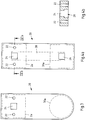
- Fig. 3 shows a plan view of a base plate 20.
- the openings 22, which correspond to the bolts 14, can be seen.
- the base plate 20 has a cable bushing 24, which is already in the Fig. 2 can be seen.
- the underground cable 18 can be passed through the cable bushing 24 from the ground foundation 8 in the direction of the housing 2.
- the base areas of the housing 2 are represented by the dashed lines 2 a, and of a mast by the dashed lines 30.
- the shape of the base plate 20 is adapted to the base surfaces 2a, 30a.
- one end of the base plate 20 may be shaped so that it is congruent to part of the base of the housing 2 and another end of the base plate 20 may be shaped so that it is congruent to part of the base of the mast.
- the base plate 20 is covered as well as possible by the housing 2 and the mast and the base plate 20 does not constitute a trip hazard.
- Figure 4a shows a further exemplary embodiment of a base plate 20.
- the base plate 20 is at least partially adapted at the respective ends to the base surfaces 2a, 30a of the housing 2 and mast.
- a further cable bushing 26 is provided in addition to the cable bushing 24 for the underground cable 18.
- the cable bushing 26 is preferably in the area in which the base of the mast rests on the base plate 20.
- the cable bushing 26 is used to enable a charging cable, which is led from the charging electronics 6 in the direction of the electric vehicle, to be led from the housing 2 into the interior of the mast.
- the base plate 20 has a groove 28.
- the groove 28 preferably runs on the side of the floor plate 20 which, in the assembled state, is directed in the direction of the floor foundation 8.
- the groove 28 preferably runs between the two cable bushings 24, 26.
- the groove 28 is in the sectional view according to Figure 4b ) shown. It can be seen there that the groove 28 is aligned with the cable bushings 24, 26. Furthermore, the openings 22 are arranged to the side of the groove 28.
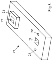
- Fig. 5 shows a further exemplary embodiment of a base plate 2, the flange 32 with which the mast can be attached to the base plate 20 is also shown here.
- the base of the flange 32 is preferably geometrically similar to the base of the mast.
- the flange 32 is geometrically congruent to an opening in the base of the mast.
- the flange 32 is preferably formed in one piece from the base plate 20 or molded onto the base plate 20.
- the flange 32 can be connected to the base plate 20 in a materially and non-positively manner. If necessary, the cable bushing 26 can be continued in the flange 32.
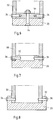
- Possible flanges 32 for connecting a mast to the base plate 20 are in the Figures 6 to 8 shown.
- Fig. 6 shows a cross section through a base plate 20 and a flange 32. A base of the mast 30 is slipped onto the flange 32.
- the flange 32 is screwed to the base plate 20 with a screw 34.
- the mast 30 can then be pushed over the flange 32.
- the mast 30 is screwed to the flange 32 with screws on the bottom, in the area of an edge on the bottom. This gives the mast 30 sufficient support.
- the screws 36 are preferably arranged circumferentially around the mast at equal angular distances from one another. Preferably four, six, eight or ten screws 36 are provided in order to screw the mast 30 to the flange 32. This also applies to the other exemplary embodiments. Instead of the screws, other fastening means, for example bolts or rivets, can also be used.
- Fig. 7 shows a further exemplary embodiment of a base plate 20, in which the flange 32 is formed in one piece with the base plate 20.
- the flange is formed by a preferably completely circumferential projection from the surface of the base plate 20.
- the mast 30 is slipped over the flange 32 on the bottom side. A screw connection then takes place with the screws 36.
- the mast 30 engages.
- the flange 32 is also preferably shaped completely circumferentially and forms a receptacle for the base of the mast 30. After the mast 30 has been inserted into the flange 32, it can be screwed with the screws 36.
- a mounted charging station 4 with mast 30 and housing 2 is in the Fig. 9 shown. It can be seen that the floor plate 20 is fastened to the floor foundation 8. The housing 2 and the mast 30 stand on the base plate 20.
- a charging cable 38 starting from the charging electronics 6, is guided through the groove 28 of the base plate 20 into the interior of the mast 30.
- the charging cable 38 is preferably held by a cable pull.
- An opening 40 is provided in the upper region of the mast 30.
- the opening 40 there are preferably pulleys so that the charging cable 38 is not damaged when it is pulled out and pulled into the mast.
- the charging cable 38 is shown in the solid line in the rest position. In this case, the charging cable 38 is pulled into the interior of the mast 30 and the charging cable plug 42 is not on the ground. To use the charging cable 38, the user can move the charging cable plug 42 and the charging cable 38 freely and, in particular, pull the charging cable 38 out of the guide within the mast 30 and move it into the desired position, as shown with the dashed lines, move. After the end of the charging process, the charging cable 38 is pulled back into the rest position by the cable pull.
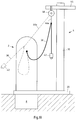
- Fig. 10 shows a further embodiment in which the charging cable 38 is also firmly attached to the housing 2.
- a cover 44 for example a transverse spar, and a spring balancer 46 arranged thereon are provided in the area of the upper end of the mast.
- the spring balancer 46 By means of the spring balancer 46, which is fastened to the charging cable 38 via a rope, the charging cable 38 can be inserted into the FIG Fig. 10 Pull the rest position shown (solid line) so that the charging cable plug 42 does not rest on the floor.
- the user can pull the charging cable 38 into the use position.
- the spring balancer 46 releases the cable 46a. After use, the charging cable 38 is pulled back into the rest position by the spring pull 46.
- Fig. 11 shows a further embodiment of a charging station 4 with a housing 2 and a mast 30.
- the charging cable 38 is connected at several points to a respective rope 46a with a respective spring balancer. This ensures that the charging cable 38 is at least partially balanced in the position of use. In particular, the weight of the charging cable 38 is at least partially balanced by the spring balancer 46 and the cable 46a.
Landscapes
- Engineering & Computer Science (AREA)
- Power Engineering (AREA)
- Transportation (AREA)
- Mechanical Engineering (AREA)
- Architecture (AREA)
- Civil Engineering (AREA)
- Structural Engineering (AREA)
- Charge And Discharge Circuits For Batteries Or The Like (AREA)
- Electric Propulsion And Braking For Vehicles (AREA)
Description
- Der Gegenstand betrifft eine Ladestation für Elektrofahrzeuge umfassend ein Gehäuse, in dem Gehäuse angeordnete Ladeelektronik, einen neben dem Gehäuse angeordneten, ein aus dem Gehäuse herausgeführtes Ladekabel führenden Mast und ein das Gehäuse tragendes Bodenfundament.
- Die Verbreitung von Ladestationen für Elektrofahrzeuge wird entscheidend sein für die Akzeptanz der Elektromobilität. Elektrisch betriebenen Fahrzeuge benötigen eine Ladeinfrastruktur, weshalb zunehmen in öffentlichen als auch halböffentlichen Räumen Ladestationen für Elektrofahrzeuge aufgestellt werden. Elektrofahrzeuge können dabei insbesondere rein batteriebetriebene elektrische Fahrzeuge (BEV, Battery Electric Vehicles) als auch Plug-in-Hybride (PHEV, Plug-in Hybrid-Electric-Vehicles). Elektrofahrzeuge können auch Elektrozweiräder sein, beispielsweise Elektroroller.
- Ein wichtiger Aspekt der Ladestationen ist der komfortable Zugang zu der bzw. die Anschlussmöglichkeit an die Ladestation. Dazu gibt es zwei verschiedene Konzepte. Zum einen gibt es das Konzept, dass die Nutzer der Elektrofahrzeuge das Ladekabel mitführen und für den Ladevorgang das Ladekabel sowohl mit der Ladestation als auch mit dem Elektrofahrzeug verbinden. Das zweite Konzept besteht darin, dass an den Ladestationen die Ladekabel fest angeschlagen sind und zur Nutzung der Ladestation lediglich der kabelendseitige Ladekabelstecker in das Fahrzeug eingesteckt werden muss.
- Gerade bei der letzteren Variante ist das Ladekabel dauerhaft an der Ladestation und muss dort so verstaut werden, dass keine Gefahr für Fußgänger oder Radfahrer besteht. Insbesondere darf das an der Ladestation angeschlagene Ladekabel nicht zu einer Stolperfalle für Fußgänger oder Radfahrer werden. Auch eine Beschädigung des Ladekabels durch ein Überfahren sollte vermieden werden.
- Um das Ladekabel vor Beschädigungen zu schützen und möglichst nicht auf dem Boden herumliegen zu lassen, gibt es Ladestationen, bei denen das Ladekabel an einem Mast geführt ist. Der Mast überragt in der Regel das Gehäuse der Ladeelektronik und ist dabei beispielsweise über zwei Meter, beispielsweise zwischen zwei und drei Meter hoch. Das Ladekabel ist an diesem Mast (auch Galgen genannt) flexibel geführt und wird bei Nichtgebrauch an den Mast herangeführt und kann durch den Nutzer bei Gebrauch von dem Mast weggezogen werden.
- Die Montage eines solchen Mastes ist jedoch herausfordernd, da große Hebelkräfte am Boden des Mastes auftreten können und der Mast sicher gegen ein Umknicken geschützt werden muss.
- Die
JP2000287310A - Dem Gegenstand lag somit die Aufgabe zugrunde, eine Ladestation mit einem Gehäuse und einem Mast zur Verfügung zu stellen, welche besonders einfach installierbar ist.
- Diese Aufgabe wird gegenständlich durch eine Ladestation nach Anspruch 1 gelöst.
- Ladestationen für Elektrofahrzeuge können unterschiedlich gestaltet sein. Eine wesentliche Gestaltungsform ist durch ein einziges Gehäuse gekennzeichnet, bei dem dieses Gehäuse die Ladeelektronik führt und als Ladesäule gebildet ist. Die zweite Gruppe an Gestaltungen weist ebenfalls ein Gehäuse mit der Ladeelektronik auf und einen daneben angeordneten Mast, an dem das Ladekabel befestigt ist. Um nun die Kosten für eine Installation einer Ladestation möglichst gering zu halten, ist man bestrebt, die Anzahl an unterschiedlichen Installationsvorgängen so gering wie möglich zu halten.
- Bei der Installation einer Ladestation ist zunächst die Ausschachtung vorzunehmen. Anschließend ist im Bereich der Ausschachtung das Fundament zu erstellen und dabei sind die elektrischen Anschlüsse erdseitig durch das Fundament zu führen. Es hat sich gezeigt, dass Fertigfundamentteile als Standardbauteile für Standardladestationen besonders kostengünstig sind. Diese lassen sich in einer genormten, industriellen Umgebung fertigen und sind somit weniger fehleranfällig als solche Fundamente, die im freien Feld jeweils individuell gegossen werden. Außerdem ist der Einbau eines Fertigfundamentes erheblich schneller bewerkstelligt, so dass in der Regel Fertigfundamente zum Einsatz kommen, die in die Ausschachtung gesetzt werden. Anschließend ist die Ausschachtung zu verfüllen und die Ladestation ist mechanisch an dem Fundament zu befestigen. Schließlich hat die elektrische Installation der Ladeelektronik innerhalb der Ladestation zu erfolgen.
- Wie ausgeführt, eignen sich insbesondere Fertigfundamente für eine unkomplizierte Installation der Ladestation. Fertigfundamente sind jedoch für bestimmte Formfaktoren von Gehäusen vorgefertigt und lassen sich nicht einfach für andere Gehäuse einsetzen. Insbesondere wenn neben dem eigentlichen Gehäuse für die Ladestation mit der Ladeelektronik auch noch ein Mast installiert werden soll, müsste in herkömmlicher Bauweise ein dafür geeignetes Fundament hergestellt werden. Dies führte dazu sich die Stückzahlen der jeweiligen Fertigfundamente verringern, da diese sich auf die jeweilig unterschiedlichen Gestaltungen der Ladestationen aufteilen.
- Erfindungsgemäß ist nun erkannt worden, dass ein für eine herkömmliche Ladestation bereitgestelltes Bodenfundament ausreichend sein kann, um hieran auch den Mast zu befestigen. Um dies zu erreichen, ist eine Bodenplatte zwischen Gehäuse und Bodenfundament angeordnet. An der Bodenplatte wird der Mast befestigt. Die Bodenplatte ist somit ein zwischen dem Gehäuse und dem Bodenfundament angeordnetes, eigenes Bauteil, welches bedarfsweise beigestellt werden kann. Wird eine Ladestation ohne Mast installiert, ist eine Bodenplatte nicht notwendig. Andererseits kann jedoch bei der Montage einer Ladestation mit Mast das herkömmliche Bodenfundament verwendet werden und darauf zunächst die Bodenplatte aufgelegt werden. Anschließend wird an der Bodenplatte sowohl das Gehäuse, als auch der Mast befestigt. Das Bodenfundament trägt dann über die Bodenplatte sowohl das Gehäuse als auch den Mast. Somit kann ein Bodenfundament sowohl für eine Ladestation mit Mast als auch eine Ladestation ohne Mast eingesetzt werden.
- Die Bodenplatte ist zwischen dem Boden des Gehäuses und der Oberseite des Bodenfundaments befestigt. Erfindungsgemäß wird die Bodenplatte zwischen dem Boden des Gehäuses und dem Bodenfundament verschraubt.
- An der Bodenplatte wird gemäß einem Ausführungsbeispiel der Mast bodenseitig befestigt. Hierbei kann der Mast an der Bodenplatte verschraubt oder verschweißt werden.
- Gemäß einem Ausführungsbeispiel wird vorgeschlagen, dass der Mast einen Federzug aufweist. An dem Federzug kann das Ladekabel befestigt werden. Insbesondere ist der Federzug im Bereich des oberen Endes des Mastes angeordnet. Der Federzug kann in einem Gehäuse des Mastes, welches beispielsweise das oberseitige Ende des Mastes abschließt, eingehaust sein. Der Federzug kann ein Seil aufweisen, mit dem das Ladekabel befestigt ist. Über den Federzug lässt sich das Ladekabel von dem Mast wegziehen. Im unbelasteten Zustand zieht der Federzug das Ladekabel zurück an den Mast, so dass dieses nicht auf dem Boden liegt.
- Auch kann der Mast ein Federmast sein oder einen Federmast aufweisen und das Ladekabel durch die Feder des Federmastes geführt werden. Durch den Federmast ist das Ladekabel flexibel an dem Mast befestigt und kann gegebenenfalls relativ zu dem Mast bzw. relativ zu dem Gehäuse bewegt werden.
- Gemäß einem Ausführungsbeispiel wird vorgeschlagen, dass das Ladekabel zumindest im Bereich des Ladekabelsteckers mit dem Federzug verbunden ist. Insbesondere ist das Ladekabel im Bereich des Ladekabelsteckers mit einem mit dem Federzug verbundenen Seil verbunden. Dadurch wird sichergestellt, dass der Ladekabelstecker stets in Richtung des Mastes im unbelasteten Zustand gezogen wird und vorzugsweise nicht auf dem Boden liegen bleibt, nachdem ein Ladevorgang abgeschlossen wurde.
- Auch kann das Ladekabel alternativ oder kumulativ in einem Mittenbereich zwischen dem Ladekabelstecker und dem Gehäuse mit dem Federzug, ggf. über ein Seil, verbunden sein. Durch geeignete Einstellung der Federkräfte des Federzugs kann das Ladekabel somit austariert sein und der Benutzer kann das Ladekabel besonders einfach an sein Fahrzeug heranführen. Die Gewichtskraft des Ladekabels kann dabei zumindest in Teilen durch den Federzug kompensiert werden.
- Gemäß einem Ausführungsbeispiel ist die Bodenplatte metallisch. Diese lässt sich besonders einfach konfektionieren, um gegebenenfalls unterschiedliche Abstände zwischen Gehäuse und Mast zu realisieren. Außerdem kann die Bodenplatte aus einem Blech beispielsweise gestanzt sein. Insbesondere kann die Bodenplatte eine Materialstärke von zwischen 0,5 mm und 5 cm aufweisen. Die Bodenplatte ist vorzugsweise aus Edelstahl gebildet.
- Gemäß einem Ausführungsbeispiel weist die Bodenplatte zumindest die Größe der Grundfläche des Gehäuses und/oder des Mastes auf. Erfindungsgemäß steht das Gehäuse mit seinem Boden vollflächig auf der Bodenplatte auf. Das Gleiche gilt vorzugsweise für den Mast, der mit seinem Boden vollflächig auf der Bodenplatte aufstehen kann. Dies führt zu einer hohen Stabilität des Gehäuses als auch des Mastes an der Bodenplatte.
- Gemäß einem Ausführungsbeispiel wird vorgeschlagen, dass die Bodenplatte einen in Richtung des Mastes ragenden Flansch aufweist und dass der Mast den Flansch bodenseitig umschließt. Auch ist es möglich, dass der Mast bodenseitig von dem Flansch umschlossen wird. Der Flansch ist vorzugsweise eine Befestigungshilfe. Die Bodenplatte ist vorzugsweise als Flachteil gebildet und lediglich dort, wo der Mast befestigt wird, kann aus der flachen Oberfläche der Flansch in der Art eines Anschlags herausragen. Der Mast kann dann über diesen Flansch gestülpt werden. Auch ist es möglich, dass der Flansch den Mast aufnimmt, so dass der Mast in den Flansch eingesteckt wird. In beiden Fällen kann, nachdem der Mast an dem Flansch angeordnet wurde, eine Befestigung des Mastes an dem Flansch erfolgen. Hierbei ist es beispielsweise möglich, dass der Mast mit radial zum Mittelpunkt des Flansches weisenden Bolzen oder Schrauben befestigt ist. Der Flansch selber kann an der Bodenplatte verschweißt oder verschraubt sein. Insbesondere kann eine axial verlaufende Schraube bzw. Bolzen durch Flansch und Bodenplatte vorgesehen sein, die den Flansch an der Bodenplatte befestigt.
- Gemäß einem Ausführungsbeispiel wird vorgeschlagen, dass die Bodenplatte eine Kabeldurchführung aufweist. Insbesondere weist die Bodenplatte eine Kabeldurchführung in dem Bereich auf, in dem der Boden des Gehäuses auf der Bodenplatte aufsitzt. Somit kann ein Erdkabel, welches zur Versorgung der Ladeelektronik mit elektrischer Leistung dient, sowohl durch das Bodenfundament als auch durch die Bodenplatte in das Innere des Gehäuses geführt werden.
- Für den Fall, dass das Ladekabel im Inneren des Mastes geführt ist, kann auch im Bereich des Mastes eine Kabeldurchführung in der Bodenplatte vorgesehen sein.
- Gemäß einem Ausführungsbeispiel ist das Ladekabel fest an dem Gehäuse angeschlagen. Das bedeutet, dass die Ladestation neben dem Gehäuse und dem Mast auch noch durch das Ladekabel gebildet ist. Dieses fest angeschlagene Kabel wird durch an dem Mast angeordnete Führungsmittel, beispielsweise den Federzug, geführt.
- Gemäß einem Ausführungsbeispiel wird vorgeschlagen, dass der Mast einen sich in Längsrichtung erstreckenden, bodenseitig offenen Hohlraum aufweist. Der Mast ist somit rohrförmig und bodenseitig offen, so dass er vorzugsweise auf den Flansch aufgesetzt werden kann. In diesem Fall kann es vorteilhaft sein, wenn das Ladekabel durch die Kabeldurchführung bodenseitig in den Hohlraum geführt ist. Dann kann das Ladekabel von dem Boden des Mastes bis in einen oberseitigen Bereich im Innern des Hohlraums geführt sein und dort aus dem Hohlraum des Mastes herausgeführt sein.
- Hierbei kann im Bereich der Durchführung des Kabels durch den Mast das Kabel durch Umlenkrollen geschützt sein.
- Innerhalb des Mastes kann das Ladekabel an einem Seilzug geführt sein. Dieser kann dafür verantwortlich sein, dass im unbelasteten Zustand das Kabel in den Mast zurückgezogen wird. Ein Nutzer kann dann unter Aufwendung einer Zugkraft das Kabel aus dem Mast herausziehen und in das Elektrofahrzeug einstecken. Nach Ende des Ladevorgangs wird das Kabel dann durch den Seilzug wieder zurück in den Mast gezogen.
- Gemäß einem Ausführungsbeispiel wird vorgeschlagen, dass die Bodenplatte eine zwischen dem Gehäuse und dem Flansch, auf der dem Bodenfundament zugewandten Seite angeordnete Nut aufweist. Die Nut ist somit durch die Bodenplatte verdeckt und verläuft zwischen Bodenfundament und Bodenplatte. In dieser Nut kann das Ladekabel zwischen dem Gehäuse und dem Mast geführt sein.
- Mit Hilfe der gegenständlichen Bodenplatte ist eine Installation einer Ladestation mit einem Gehäuse und einem Mast in besonders einfacher Weise möglich.
- Nachfolgend wird der Gegenstand anhand einer Ausführungsbeispiele zeigenden Zeichnung näher erläutert. In der Zeichnung zeigen:
- Fig. 1
- eine schematische Ansicht eines Gehäuses einer Ladestation mit einem Bodenfundament;
- Fig. 2
- eine schematische Ansicht des Aufbaus gemäß
Fig. 1 mit einer Bodenplatte; - Fig. 3
- eine Draufsicht auf eine Bodenplatte gemäß einem Ausführungsbeispiel;
- Fig. 4a),b)
- Ansichten einer Bodenplatte gemäß einem Ausführungsbeispiel;
- Fig. 5
- Ansicht einer Bodenplatte gemäß einem Ausführungsbeispiel;
- Fig. 6
- eine schematische Ansicht einer Befestigung eines Mastes an einem Flansch;
- Fig. 7
- eine weitere schematische Ansicht einer Befestigung eines Mastes an einem Flansch;
- Fig. 8
- eine weitere schematische Ansicht einer Befestigung eines Mastes an einem Flansch;
- Fig. 9
- eine Ladestation mit einem Gehäuse und einem Mast gemäß einem Ausführungsbeispiel;
- Fig. 10
- eine Ladestation mit einem Gehäuse und einem Mast gemäß einem weiteren Ausführungsbeispiel;
- Fig. 11
- eine Ladestation mit einem Gehäuse und einem Mast gemäß einem weiteren Ausführungsbeispiel.
-
Fig. 1 zeigt in einer schematischen Schnittansicht ein Gehäuse 2 einer Ladestation 4 mit einer Ladeelektronik 6. Die Ladeelektronik 6 ist im Inneren des Gehäuses 2 untergebracht. - Das Gehäuse 2 ist auf einem Bodenfundament 8 aufsetzbar. Das Bodenfundament 8 ist dabei vorzugsweise ein Betonfundament, insbesondere ein Betongussteil. Das Bodenfundament 8 kann ein Fertiggussteil sein, welches fertig gegossen in eine Ausschachtung 10 eingesetzt wird. Anschließend wir die Ausschachtung 10 mit einem Füllmaterial verfüllt.
- An dem Bodenfundament 8 sind vorzugsweise oberseitig herausragende Schrauben oder Bolzen 14 vorgesehen. Die Bolzen 14 sind in dem Bodenfundament fest verankert und korrespondieren mit Öffnungen 16 im Boden des Gehäuses 2.
- Zur Montage der Ladestation 4 wird zunächst die Ausschachtung 10 hergestellt. Anschließend wird ein Erdkabel 18, welches eine elektrische Verbindung zu einem elektrischen Versorgungsnetz herstellt, in die Ausschachtung 10 geführt. Auch ist es möglich, dass das Erdkabel 18 bereits in der Ausschachtung 10 liegt.
- Anschließend wird das Bodenfundament 8 in die Ausschachtung 10 eingesetzt und das Erdkabel 18 wird durch eine Durchführung in dem Bodenfundament 8 zu der Oberseite des Bodenfundaments 8 geführt. Anschließend wird die Ausschachtung 10 mit Füllmaterial 12 verfüllt, so dass das Bodenfundament 8 sicher im Erdreich gehalten ist.
- Danach wird das Gehäuse 2 mit seinen Öffnungen 16 auf die Bolzen 14 aufgesetzt und an den Bolzen 14 verschraubt. Dies gewährleistet einen sicheren Stand des Gehäuses 2 auf dem Bodenfundament 8.
- Abschließend wird die Ladeelektronik 6 noch mit dem Erdkabel 18 verbunden, so dass die Ladestation 4 elektrisch angeschlossen ist.
- Es ist jedoch so, dass nicht nur solche Ladestationen mit einem einzigen Gehäuse 2 in Betrieb genommen werden, sondern auch solche Ladestationen, die neben dem Gehäuse 2 mit einem zusätzlichen Mast versehen sind. Der Mast steht dabei in der Regel seitlich des Gehäuses 2. Der Mast dient in der Regel dazu, ein fest an dem Gehäuse 2 angeschlagenes Ladekabel zu führen, so dass dies in der Ruhestellung nicht auf dem Boden liegt und von dieser Ruhestellung durch den Nutzer in eine Gebrauchsstellung gezogen werden kann. Dabei soll das Ladekabel möglichst flexibel an unterschiedliche Positionen in Gebrauchsstellung gezogen werden können, weshalb der Mast vorzugsweise eine Rückführung für das Ladekabel in seine Ruhestellung gewährleistet.
- Um sicherzustellen, dass das Ladekabel in der Ruhestellung nicht auf dem Boden aufliegt, hat der Mast eine gewisse Höhe, die beispielsweise über 2 m, insbesondere über 2,50, insbesondere über 2,80m, beispielsweise bei 2,85 m liegt. Ein solcher Mast darf jedoch nicht umkippen, so dass auch dieser Mast ein Fundament braucht.
- Es wurde nun erkannt, dass es vorteilhaft ist, wenn das Bodenfundament 8 einer herkömmlichen Ladestation mit nur einem Gehäuse 2 auch für die Befestigung des Mastes, wie in der
Fig. 2 dargestellt, eingesetzt werden kann. Neben den in derFig. 1 dargestellten Elemente weist dieFig. 2 noch die Bodenplatte 20 auf. Die Bodenplatte 20 ist vorzugsweise aus Metall. Die Bodenplatte 20 ist vorzugsweise ein Flachteil. Die Bodenplatte 20 ist insbesondere ein Metallblech, insbesondere aus Edelstahl. Die Bodenplatte 20 ist vorzugsweise ein Stanzteil, welches aus einem Metallblech ausgestanzt wurde. - Die Bodenplatte 20 weist zumindest Öffnungen 22 auf, die mit den Bolzen 14 korrespondieren. Bevor das Gehäuse 2 auf die Bodenplatte 8 aufgesetzt wird, wird die Bodenplatte 20 mit den Öffnungen 22 über die Bolzen 14 gesteckt. Anschließend wir das Gehäuse 2 wie oben beschrieben, mit den Öffnungen 16 auf die Bolzen 14 gesetzt und dort verschraubt. Diese Verschraubung bewirkt, dass die Bodenplatte 20 zwischen dem Gehäuse 2 und dem Bodenfundament 8 durch die Bolzen 14 fixiert ist.
- Auch ist zu erkennen, dass die Bodenplatte 20 über die Grundfläche des Bodenfundaments 8 hinausragen kann und beispielsweise auf dem Erdreich aufliegt. Dies ist jedoch unproblematisch, da die Bodenplatte 20 eine ausreichende Stabilität für einen Mast bietet, der dann an der Bodenplatte 20 angeordnet werden kann. Die Bodenplatte 20 bildet somit das Fundament für den Mast und ist ihrerseits über ein Bodenfundament 8 im Erdreich verankert.
- Die Bodenplatte 20 ist beispielhaft in den
Figuren 3 bis 5 in Ausführungsbeispielen gezeigt. -
Fig. 3 zeigt eine Draufsicht auf eine Bodenplatte 20. Zu erkennen sind die Öffnungen 22, die zu den Bolzen 14 korrespondieren. Ferner weist die Bodenplatte 20 eine Kabeldurchführung 24 auf, welche auch schon in derFig. 2 zu erkennen ist. Durch die Kabeldurchführung 24 lässt sich das Erdkabel 18 von dem Bodenfundament 8 in Richtung des Gehäuses 2 durchführen. - Ferner ist in der
Fig. 3 eine beispielhafte Form einer Bodenplatte 20 gezeigt. Mit den gestrichelten Linien sind die Grundflächen sowohl des Gehäuses 2 durch die gestrichelten Linien 2a, als auch eines Mastes durch die gestrichelten Linien 30 dargestellt. Wie zu erkennen ist, ist die Bodenplatte 20 in ihrer Form an die Grundflächen 2a, 30a angepasst. Beispielsweise kann ein Ende der Bodenplatte 20 so geformt sein, dass es kongruent zu einem Teil der Grundfläche des Gehäuses 2 ist und ein anderes Ende der Bodenplatte 20 kann so geformt sein, dass es kongruent zu einem Teil der Grundfläche des Mastes ist. Dadurch wird die Bodenplatte 20 durch das Gehäuse 2 und den Mast möglichst gut verdeckt und die Bodenplatte 20 bildet keine Stolperfalle. -
Fig. 4a ) zeigt ein weiteres Ausführungsbeispiel einer Bodenplatte 20. Auch hier ist zu erkennen, dass die Bodenplatte 20 an den jeweiligen Enden zumindest in Teilen an die Grundflächen 2a, 30a von Gehäuse 2 und Mast angepasst ist. Außerdem ist zu erkennen, dass neben der Kabeldurchführung 24 für das Erdkabel 18 eine weitere Kabeldurchführung 26 vorgesehen ist. Die Kabeldurchführung 26 ist vorzugsweise in dem Bereich, in dem die Grundfläche des Mastes auf der Bodenplatte 20 aufsteht. Die Kabeldurchführung 26 dient dazu, ein Ladekabel, welches ausgehend von der Ladeelektronik 6 in Richtung des Elektrofahrzeugs geführt wird, zunächst von dem Gehäuse 2 in das Innere des Mastes geführt werden kann. - Darüber hinaus weist die Bodenplatte 20 eine Nut 28 auf. Die Nut 28 verläuft vorzugsweise auf der Seite der Bodenplatte 20, die im montierten Zustand in Richtung des Bodenfundaments 8 gerichtet ist. Ferner verläuft die Nut 28 vorzugsweise zwischen den beiden Kabeldurchführungen 24, 26.
- Die Nut 28 ist in der Schnittansicht gemäß
Fig. 4b ) dargestellt. Dort ist zu erkennen, dass die Nut 28 mit den Kabeldurchführungen 24, 26 fluchtet. Ferner sind die Öffnungen 22 seitlich von der Nut 28 angeordnet. -
Fig. 5 zeigt ein weiteres Ausführungsbeispiel einer Bodenplatte 2, wobei hier zusätzlich der Flansch 32 gezeigt ist, mit welchem der Mast an der Bodenplatte 20 befestigt werden kann. - Der Flansch 32 ist in seiner Grundfläche vorzugsweise geometrisch ähnlich zu der Grundfläche des Mastes. Insbesondere ist der Flansch 32 geometrisch kongruent zu einer Öffnung im Boden des Mastes. Der Flansch 32 ist vorzugsweise einstückig aus der Bodenplatte 20 geformt oder an die Bodenplatte 20 angeformt. Dabei kann der Flansch 32 stoffschlüssig als auch kraftschlüssig mit der Bodenplatte 20 verbunden sein. In dem Flansch 32 kann, falls notwendig, die Kabeldurchführung 26 fortgeführt sein. Mögliche Flansche 32 zur Verbindung eines Mastes mit der Bodenplatte 20 sind in den
Figuren 6 bis 8 dargestellt. -
Fig. 6 zeigt einen Querschnitt durch eine Bodenplatte 20 und einen Flansch 32. Auf den Flansch 32 ist ein Boden des Mastes 30 aufgesteckt. - Wie zu erkennen ist, ist der Flansch 32 mit einer Schraube 34 mit der Bodenplatte 20 verschraubt. Anschließend lässt sich der Mast 30 über den Flansch 32 stecken. Schließlich wird der Mast 30 bodenseitig, im Bereich einer bodenseitigen Kante, mit Schrauben an dem Flansch 32 verschraubt. Dies gibt dem Mast 30 einen ausreichenden Halt. Die Schrauben 36 sind vorzugsweise umlaufend um den Mast in gleichen Winkelabständen zueinander angeordnet. Vorzugsweise sind vier, sechs, acht oder zehn Schrauben 36 vorgesehen, um den Mast 30 mit dem Flansch 32 zu verschrauben. Dies gilt auch für die weiteren Ausführungsbeispiele. Anstelle der Schrauben können auch andere Befestigungsmittel, z.B. Bolzen oder Nieten verwendet werden.
-
Fig. 7 zeigt ein weiteres Ausführungsbeispiel einer Bodenplatte 20, bei dem der Flansch 32 einstückig mit der Bodenplatte 20 gebildet ist. Der Flansch ist dabei durch eine vorzugsweise vollständig umlaufende Auskragung aus der Oberfläche der Bodenplatte 20 gebildet. Der Mast 30 wird bodenseitig über den Flansch 32 gestülpt. Anschließend erfolgt eine Verschraubung mit den Schrauben 36. - Auch ist es möglich, dass der Flansch 32, wie in
Fig. 8 gezeigt, den Mast 30 umgreift. Hierbei ist der Flansch 32 ebenfalls vorzugsweise vollständig umlaufend geformt und bildet eine Aufnahme für den Boden des Mastes 30. Nachdem der Mast 30 in den Flansch 32 eingesteckt wurde, kann dieser mit den Schrauben 36 verschraubt werden. - Eine montierte Ladestation 4 mit Mast 30 und Gehäuse 2 ist in der
Fig. 9 gezeigt. Zu erkennen ist, dass die Bodenplatte 20 an dem Bodenfundament 8 befestigt ist. Auf der Bodenplatte 20 steht das Gehäuse 2 als auch der Mast 30. - In dem in
Fig. 9 gezeigten Ausführungsbeispiel ist ein Ladekabel 38 ausgehend von der Ladeelektronik 6 durch die Nut 28 der Bodenplatte 20 in das Innere des Mastes 30 geführt. Im Inneren des Mastes 30 ist das Ladekabel 38 vorzugweise durch einen Seilzug gehalten. - Im oberen Bereich des Mastes 30 ist eine Öffnung 40 vorgesehen. In der Öffnung 40 sind vorzugsweise Umlenkrollen, so dass das Ladekabel 38 beim Herausziehen und Einziehen in den Mast nicht beschädigt wird.
- Das Ladekabel 38 ist in der durchgezogenen Linie in der Ruhestellung dargestellt. Hierbei ist das Ladekabel 38 in das Innere des Mastes 30 gezogen und der Ladekabelstecker 42 liegt nicht auf dem Boden auf. Zur Nutzung des Ladekabels 38 kann der Nutzer den Ladekabelstecker 42 und das Ladekabel 38 frei bewegen und insbesondere das Ladekabel 38 aus der Führung innerhalb des Mastes 30 herausziehen und so in die gewünschte Position, wie sie mit den gestrichelten Linien dargestellt ist, bewegen. Nach Beendigung des Ladevorgangs wird das Ladekabel 38 durch den Seilzug wieder in die Ruhestellung zurück gezogen.
-
Fig. 10 zeigt ein weiteres Ausführungsbeispiel, bei dem das Ladekabel 38 ebenfalls fest an dem Gehäuse 2 angeschlagen ist. In diesem Ausführungsbeispiel ist im Bereich des oberen Ende des Mastes beispielsweise eine Abdeckung 44, beispielsweise ein Querholm sowie ein daran angeordneter Federzug 46 vorgesehen. Mittels des Federzugs 46, der über ein Seil an dem Ladekabel 38 befestigt ist, lässt sich das Ladekabel 38 in die inFig. 10 gezeigte Ruhestellung (durchgezogene Linie) ziehen, so dass der Ladekabelstecker 42 nicht auf dem Boden aufliegt. Zur Nutzung kann der Nutzer das Ladekabel 38 in die Gebrauchsstellung ziehen. Dazu gibt der Federzug 46 das Seil 46a frei. Nach Gebrauch wird das Ladekabel 38 durch den Federzug 46 wieder in die Ruhestellung zurückgezogen. -
Fig. 11 zeigt ein weiteres Ausführungsbeispiel einer Ladestation 4 mit einem Gehäuse 2 und einem Mast 30. Hierbei ist das Ladekabel 38 an mehreren Punkten mit einem jeweiligen Seil 46a mit einem jeweiligen Federzug verbunden. Hierdurch wird erreicht, dass in der Gebrauchsstellung das Ladekabel 38 zumindest teilweise austariert ist. Insbesondere wird die Gewichtskraft des Ladekabels 38 zumindest teilweise durch den Federzug 46 und das Seil 46a austariert. -
- 2
- Gehäuse
- 2a
- Grundfläche Gehäuse
- 4
- Ladestation
- 6
- Ladeelektronik
- 8
- Bodenfundament
- 10
- Ausschachtung
- 12
- Füllmaterial
- 14
- Bolzen
- 16
- Öffnung
- 18
- Erdkabel
- 20
- Bodenplatte
- 22
- Öffnung
- 24,26
- Kabeldurchführung
- 28
- Nut
- 30
- Mast
- 30a
- Grundfläche Mast
- 32
- Flansch
- 34,36
- Schrauben/Bolzen
- 38
- Ladekabel
- 40
- Öffnung
- 42
- Ladekabelstecker
- 44
- Abdeckung
- 46
- Federzug
- 46a
- Seil
Claims (12)
- Ladestation (4) für Elektrofahrzeuge umfassend:- ein Gehäuse (2),- in dem Gehäuse (2) angeordnete Ladeelektronik,- einen neben dem Gehäuse (2) angeordneten, ein aus dem Gehäuse (2) heraus geführtes Ladekabel (38) führenden Mast (30), und- ein das Gehäuse (2) tragendes Bodenfundament (8), wobei- eine Bodenplatte (20) auf das Bodenfundament (8) aufgelegt ist, und an der Bodenplatte (20) der Mast (30) befestigt ist,dadurch gekennzeichnet,- dass das Gehäuse (2) mit seinem Boden vollflächig auf der Bodenplatte aufsteht,- dass die Bodenplatte zwischen dem Boden des Gehäuses (2) und einer Oberseite des Bodenfundaments (8) verschraubt ist.
- Ladestation (4) nach Anspruch 1,
dadurch gekennzeichnet,- dass der Mast (30) bodenseitig an der Bodenplatte (20) befestigt ist und dass der Mast (30) das Ladekabel (38) an seiner Oberseite hält. - Ladestation (4) nach Anspruch 1 oder 2,
dadurch gekennzeichnet,- dass der Mast (30) einen Federzug (46)aufweist, dass das Ladekabel (38) an dem Federzug (46)befestigt ist und/oder dass der Mast (30) einen Federmast aufweist, dass das Ladekabel (38) an dem Federmast befestigt ist. - Ladestation (4) nach einem der vorangehenden Ansprüche,
dadurch gekennzeichnet,- dass das Ladekabel (38) zumindest im Bereich des Ladekabelsteckers (42) mit dem Federzug (46)verbunden ist, und/oder dass das Ladekabel (38) in einem Mittenbereich zwischen dem Ladekabelstecker (42) und dem Gehäuse (2) mit dem Federzug (46)verbunden ist. - Ladestation (4) nach einem der vorangehenden Ansprüche,
dadurch gekennzeichnet,- dass die Bodenplatte (20) metallisch ist. - Ladestation (4) nach einem der vorangehenden Ansprüche,
dadurch gekennzeichnet,- dass die Bodenplatte (20) zumindest die Größe der Grundfläche des Gehäuses (2) und des Mastes (30) aufweist. - Ladestation (4) nach einem der vorangehenden Ansprüche,
dadurch gekennzeichnet,- dass die Bodenplatte (20) einen in Richtung des Masts (30) ragenden Flansch (32) aufweist und dass der Mast (30) den Flansch (32) bodenseitig umschließt. - Ladestation (4) nach einem der vorangehenden Ansprüche,
dadurch gekennzeichnet,- dass die Bodenplatte (20) im Bereich des Gehäuses (2) eine Kabeldurchführung (24, 26) aufweist. - Ladestation (4) nach einem der vorangehenden Ansprüche,
dadurch gekennzeichnet,- dass das Ladekabel (38) fest an dem Gehäuse (2) angeschlagen ist. - Ladestation (4) nach einem der vorangehenden Ansprüche,
dadurch gekennzeichnet,- dass der Mast (30) einen sich in Längsrichtung erstreckenden, bodenseitig offenen Hohlraum aufweist und insbesondere dass das Ladekabel (38) bodenseitig in den Hohlraum geführt ist und in einem oberseitigen Bereich des Masts (30) aus dem Hohlraum heraus geführt ist. - Ladestation (4) nach einem der vorangehenden Ansprüche,
dadurch gekennzeichnet,- dass das Ladekabel (38) in dem Mast (30) an einem Seilzug geführt ist. - Ladestation (4) nach einem der vorangehenden Ansprüche,
dadurch gekennzeichnet,- dass die Bodenplatte (20) eine zwischen dem Gehäuse (2) und der Halterung, auf der dem Bodenfundament (8) zugewandten Seite angeordnete Nut (28) aufweist.
Applications Claiming Priority (2)
| Application Number | Priority Date | Filing Date | Title |
|---|---|---|---|
| DE102017113224.4A DE102017113224A1 (de) | 2017-06-16 | 2017-06-16 | Ladestation |
| PCT/EP2018/057756 WO2018228731A1 (de) | 2017-06-16 | 2018-03-27 | Ladestation |
Publications (2)
| Publication Number | Publication Date |
|---|---|
| EP3639335A1 EP3639335A1 (de) | 2020-04-22 |
| EP3639335B1 true EP3639335B1 (de) | 2021-06-02 |
Family
ID=61801965
Family Applications (1)
| Application Number | Title | Priority Date | Filing Date |
|---|---|---|---|
| EP18713905.0A Active EP3639335B1 (de) | 2017-06-16 | 2018-03-27 | Ladestation |
Country Status (5)
| Country | Link |
|---|---|
| US (1) | US20200114774A1 (de) |
| EP (1) | EP3639335B1 (de) |
| CA (1) | CA3067438C (de) |
| DE (1) | DE102017113224A1 (de) |
| WO (1) | WO2018228731A1 (de) |
Cited By (1)
| Publication number | Priority date | Publication date | Assignee | Title |
|---|---|---|---|---|
| DE102022001492A1 (de) | 2022-04-28 | 2023-11-02 | Oliver Jauch | Fundamentblock zur Erzeugung eines ortsfesten Ladepunktes für Elektrofahrzeuge sowie Infrastruktur zur Erzeugung zumindest eines solchen Ladepunktes |
Families Citing this family (16)
| Publication number | Priority date | Publication date | Assignee | Title |
|---|---|---|---|---|
| DE102017118300A1 (de) * | 2017-08-11 | 2019-02-14 | Elektro-Bauelemente Gmbh | Ladestation für Elektrofahrzeuge mit einem höhenverstellbar gehaltenen Ladekabelstecker |
| DE102018122828A1 (de) * | 2018-09-18 | 2020-03-19 | Innogy Se | Ladestation für Elektrofahrzeuge |
| DE102019104107A1 (de) * | 2019-02-19 | 2020-08-20 | Innogy Se | Ladestationsmontageadapter, System mit einem solchen Adapter und Verfahren zur Montage einer Ladestation |
| DE102019213451A1 (de) * | 2019-09-04 | 2021-03-04 | Volkswagen Aktiengesellschaft | Ladestation für ein elektrisch betriebenes Fahrzeug |
| DE102019126794A1 (de) * | 2019-10-04 | 2021-04-08 | Compleo Charging Solutions Ag | Kabelhalteanordnung für ein Anschlusskabel einer Versorgungsstation |
| CN111462455A (zh) * | 2020-04-20 | 2020-07-28 | 湖州杰卡汽车用品有限公司 | 一种新能源汽车充电桩防碰撞报警装置 |
| DE102020207218A1 (de) | 2020-06-09 | 2021-12-23 | Volkswagen Aktiengesellschaft | Ladestation für ein elektrisch betriebenes Fahrzeug |
| CN112356703A (zh) * | 2020-10-12 | 2021-02-12 | 苏州青众创业服务有限公司 | 一种新能源快速充电桩 |
| CN112140933B (zh) * | 2020-10-21 | 2022-05-24 | 阳光电源股份有限公司 | 一种充电桩 |
| CN112977132A (zh) * | 2021-03-08 | 2021-06-18 | 顾朝文 | 一种多功能的基于物联网的电动汽车充电桩 |
| CN113022348B (zh) * | 2021-03-10 | 2021-10-22 | 嘉兴智行物联网技术有限公司 | 一种电动自行车充电桩安装板及其安装装置 |
| EP4113770A1 (de) * | 2021-06-28 | 2023-01-04 | CTEK Sweden AB | Kabelhandhabungsanordnung |
| WO2023250496A1 (en) * | 2022-06-24 | 2023-12-28 | Ross Jette | System and method for installing charging dispensers for an electric vehicle |
| EP4456356A1 (de) * | 2023-04-26 | 2024-10-30 | ABB E-mobility B.V. | Kabelmanagementsystem für eine elektrofahrzeugladestation und elektrofahrzeugladestation |
| DE102023205169B4 (de) * | 2023-06-02 | 2025-11-27 | Siemens Aktiengesellschaft | Kabelmanagement für Ladestationen von Fahrzeugen |
| DE102023127858A1 (de) | 2023-10-12 | 2025-04-17 | Audi Aktiengesellschaft | Carport mit betonfreier Bodenverankerung mit Befestigungsschnittstelle und Versorgungsanschluss für eine Befestigung und Versorgung eines Anbauteils |
Family Cites Families (21)
| Publication number | Priority date | Publication date | Assignee | Title |
|---|---|---|---|---|
| JP2000287310A (ja) * | 1999-03-29 | 2000-10-13 | Harness Syst Tech Res Ltd | 電気自動車用充電設備の除湿装置 |
| GB0820314D0 (en) * | 2008-11-06 | 2008-12-17 | Wilson Russell D | Electric vehicle charging station |
| DE102009016503A1 (de) * | 2009-04-08 | 2010-10-14 | Rwe Ag | Ladesäulensockel für elektrische Ladesäulen |
| DE102009016505A1 (de) * | 2009-04-08 | 2010-10-14 | Rwe Ag | Ladesäule für Elektrofahrzeuge |
| DE102009024721A1 (de) * | 2009-06-12 | 2010-12-16 | Erwin Bienek | Dezentrale Ladestation für batteriebetriebene Elektromobile |
| US9457674B2 (en) * | 2009-09-25 | 2016-10-04 | Control Module, Inc. | Overhead power cable management system |
| US8829851B2 (en) * | 2010-07-13 | 2014-09-09 | Green Charge Networks Llc | Single electric vehicle charger for electrically connecting to multiple electric vehicles simultaneously while automatically charging the multiple electric vehicles sequentially |
| DE102011006104B4 (de) * | 2010-09-15 | 2026-05-21 | Kiekert Aktiengesellschaft | Ladeeinrichtung für ein Elektrofahrzeug |
| DE202011100062U1 (de) * | 2011-04-30 | 2011-11-21 | Semperlux Aktiengesellschaft - Lichttechnische Werke - | Außenleuchte mit Elektroladestation |
| GB201115322D0 (en) * | 2011-09-06 | 2011-10-19 | Electric Car Charging Company Ltd | An improved lamp column |
| US9561731B2 (en) * | 2011-12-13 | 2017-02-07 | Brightfield Transportation Solutions, Inc. | Structural bollard assembly for electric vehicle infrastructure |
| FR2998110B1 (fr) * | 2012-11-13 | 2019-11-15 | Al-Babtain France Sas | Lampadaire muni de prises de rechargement de vehicules |
| DE202013101890U1 (de) * | 2013-04-30 | 2013-05-17 | Quantys Gmbh | Fahrzeugunterstand |
| GB2526307A (en) * | 2014-05-20 | 2015-11-25 | Bombardier Transp Gmbh | A housing for at least one object detection device, a primary unit and a pavement slab assembly |
| DE202014005149U1 (de) * | 2014-06-25 | 2014-07-29 | Arau Technik Gmbh | Carportsystem, insbesondere Solar-Carportsystem |
| EP2993748A1 (de) * | 2014-09-04 | 2016-03-09 | Heberger GmbH | Ladesäule für elektrisch betriebene Fahrzeuge |
| KR20160125848A (ko) * | 2015-04-22 | 2016-11-01 | 엘에스산전 주식회사 | 전기차 충전기의 컨트롤박스 |
| US20170259678A1 (en) * | 2016-03-08 | 2017-09-14 | Faraday&Future Inc. | Electric vehicle charge port |
| US10131237B2 (en) * | 2016-06-22 | 2018-11-20 | Ford Global Technologies, Llc | Illuminated vehicle charging system |
| KR101737819B1 (ko) * | 2016-12-12 | 2017-05-22 | 보타리에너지 주식회사 | 전기차 충전기 다기능 기초대 및 시공방법 |
| US10084337B1 (en) * | 2017-04-20 | 2018-09-25 | Lew Electric Fittings Company | Spill proof electrical charger |
-
2017
- 2017-06-16 DE DE102017113224.4A patent/DE102017113224A1/de not_active Withdrawn
-
2018
- 2018-03-27 EP EP18713905.0A patent/EP3639335B1/de active Active
- 2018-03-27 WO PCT/EP2018/057756 patent/WO2018228731A1/de not_active Ceased
- 2018-03-27 CA CA3067438A patent/CA3067438C/en active Active
-
2019
- 2019-12-16 US US16/716,002 patent/US20200114774A1/en not_active Abandoned
Cited By (1)
| Publication number | Priority date | Publication date | Assignee | Title |
|---|---|---|---|---|
| DE102022001492A1 (de) | 2022-04-28 | 2023-11-02 | Oliver Jauch | Fundamentblock zur Erzeugung eines ortsfesten Ladepunktes für Elektrofahrzeuge sowie Infrastruktur zur Erzeugung zumindest eines solchen Ladepunktes |
Also Published As
| Publication number | Publication date |
|---|---|
| DE102017113224A1 (de) | 2018-12-20 |
| CA3067438A1 (en) | 2018-12-20 |
| WO2018228731A1 (de) | 2018-12-20 |
| EP3639335A1 (de) | 2020-04-22 |
| US20200114774A1 (en) | 2020-04-16 |
| CA3067438C (en) | 2020-11-17 |
Similar Documents
| Publication | Publication Date | Title |
|---|---|---|
| WO2018228731A1 (de) | Ladestation | |
| EP2416983B1 (de) | Ladesäule für elektrofahrzeuge | |
| EP2417679B1 (de) | Ladesäulensockel für elektrische ladesäulen | |
| EP2281116B1 (de) | Windenergieanlage mit stromschienen | |
| EP3406898A1 (de) | Gondelkomponente für eine windenergieanlage und verfahren zum montieren einer gondelkomponente | |
| DE1750240A1 (de) | Wanddurchfuehrung fuer Rohre,elektrische Kabel od.dgl. | |
| EP3711138B1 (de) | Ladestation für elektrofahrzeuge | |
| WO2019228678A1 (de) | Ladesäule für elektrofahrzeuge | |
| EP3947025A1 (de) | Anschlussvorrichtung zum laden eines elektrofahrzeugs | |
| EP3047083B1 (de) | Variables schutzdach | |
| DE4215743A1 (de) | Kabelbaum für ein Kraftfahrzeug mit Kabelbaumsteckern | |
| EP2916407A1 (de) | Verfahren zum zugfesten Abschließen des Endes eines Energiekabels und damit hergestellte Vorrichtung | |
| DE10227145A1 (de) | Vogelabweiser sowie Montagestange hierfür | |
| EP4047137A1 (de) | Fundament für eine säule mit innen geführten kabeln, beispielsweise für eine elektrofahrzeug-ladesäule oder einen parkscheinautomaten | |
| DE618697C (de) | Als Abzweigdose und zum Einbau elektrischer Installationsapparate geeignete gas- undwasserdichte Dose aus Isolierstoff | |
| DE202010009722U1 (de) | Kabel- und Leitungsführung | |
| EP1985502A1 (de) | Kabelführung in einer Antriebseinheit eines deichselgelenkten Flurförderzeugs | |
| DE102007062956B3 (de) | Montagehilfe für das Montieren von wenigstens zwei Kabelschuhen | |
| DE202022002900U1 (de) | Verbundisolator | |
| DE102009031446A1 (de) | Verbindungsmuffe für Innenkonus-Kabelendverschlüsse sowie Verfahren zur Herstellung der Verbindungsmuffe | |
| EP2405536B1 (de) | Fremdstartpunkt | |
| DE102019104375B4 (de) | System zur Positionierung einer Einrichtung, Kanalsystem und Verfahren zur Ladung eines zur induktiven Ladung eingerichteten Gegenstands | |
| EP3113310A1 (de) | Endenabschluss für ein kabel und verfahren zu seiner herstellung | |
| DE19530163C2 (de) | Hochspannungsausleitungs- und -durchführungsanordnung für Transformatoren oder Drosselspulen | |
| EP3164919B1 (de) | Kabelendverschluss zur anbindung einer schaltanlage an ein hochspannungskabel |
Legal Events
| Date | Code | Title | Description |
|---|---|---|---|
| STAA | Information on the status of an ep patent application or granted ep patent |
Free format text: STATUS: UNKNOWN |
|
| STAA | Information on the status of an ep patent application or granted ep patent |
Free format text: STATUS: THE INTERNATIONAL PUBLICATION HAS BEEN MADE |
|
| PUAI | Public reference made under article 153(3) epc to a published international application that has entered the european phase |
Free format text: ORIGINAL CODE: 0009012 |
|
| STAA | Information on the status of an ep patent application or granted ep patent |
Free format text: STATUS: REQUEST FOR EXAMINATION WAS MADE |
|
| 17P | Request for examination filed |
Effective date: 20191209 |
|
| AK | Designated contracting states |
Kind code of ref document: A1 Designated state(s): AL AT BE BG CH CY CZ DE DK EE ES FI FR GB GR HR HU IE IS IT LI LT LU LV MC MK MT NL NO PL PT RO RS SE SI SK SM TR |
|
| AX | Request for extension of the european patent |
Extension state: BA ME |
|
| GRAP | Despatch of communication of intention to grant a patent |
Free format text: ORIGINAL CODE: EPIDOSNIGR1 |
|
| STAA | Information on the status of an ep patent application or granted ep patent |
Free format text: STATUS: GRANT OF PATENT IS INTENDED |
|
| RIC1 | Information provided on ipc code assigned before grant |
Ipc: H02G 3/04 20060101AFI20200713BHEP Ipc: B60L 53/31 20190101ALI20200713BHEP Ipc: H02G 11/00 20060101ALI20200713BHEP |
|
| DAV | Request for validation of the european patent (deleted) | ||
| DAX | Request for extension of the european patent (deleted) | ||
| INTG | Intention to grant announced |
Effective date: 20200819 |
|
| RIN1 | Information on inventor provided before grant (corrected) |
Inventor name: STEFAN, HELNERUS Inventor name: WAFFNER, JUERGEN |
|
| GRAJ | Information related to disapproval of communication of intention to grant by the applicant or resumption of examination proceedings by the epo deleted |
Free format text: ORIGINAL CODE: EPIDOSDIGR1 |
|
| STAA | Information on the status of an ep patent application or granted ep patent |
Free format text: STATUS: REQUEST FOR EXAMINATION WAS MADE |
|
| GRAS | Grant fee paid |
Free format text: ORIGINAL CODE: EPIDOSNIGR3 |
|
| STAA | Information on the status of an ep patent application or granted ep patent |
Free format text: STATUS: GRANT OF PATENT IS INTENDED |
|
| GRAP | Despatch of communication of intention to grant a patent |
Free format text: ORIGINAL CODE: EPIDOSNIGR1 |
|
| INTC | Intention to grant announced (deleted) | ||
| INTG | Intention to grant announced |
Effective date: 20210118 |
|
| GRAA | (expected) grant |
Free format text: ORIGINAL CODE: 0009210 |
|
| STAA | Information on the status of an ep patent application or granted ep patent |
Free format text: STATUS: THE PATENT HAS BEEN GRANTED |
|
| REG | Reference to a national code |
Ref country code: CH Ref legal event code: EP |
|
| AK | Designated contracting states |
Kind code of ref document: B1 Designated state(s): AL AT BE BG CH CY CZ DE DK EE ES FI FR GB GR HR HU IE IS IT LI LT LU LV MC MK MT NL NO PL PT RO RS SE SI SK SM TR |
|
| REG | Reference to a national code |
Ref country code: GB Ref legal event code: FG4D Free format text: NOT ENGLISH |
|
| REG | Reference to a national code |
Ref country code: AT Ref legal event code: REF Ref document number: 1399326 Country of ref document: AT Kind code of ref document: T Effective date: 20210615 |
|
| REG | Reference to a national code |
Ref country code: IE Ref legal event code: FG4D Free format text: LANGUAGE OF EP DOCUMENT: GERMAN |
|
| REG | Reference to a national code |
Ref country code: DE Ref legal event code: R096 Ref document number: 502018005522 Country of ref document: DE |
|
| REG | Reference to a national code |
Ref country code: NL Ref legal event code: FP |
|
| REG | Reference to a national code |
Ref country code: SE Ref legal event code: TRGR |
|
| REG | Reference to a national code |
Ref country code: LT Ref legal event code: MG9D |
|
| PG25 | Lapsed in a contracting state [announced via postgrant information from national office to epo] |
Ref country code: BG Free format text: LAPSE BECAUSE OF FAILURE TO SUBMIT A TRANSLATION OF THE DESCRIPTION OR TO PAY THE FEE WITHIN THE PRESCRIBED TIME-LIMIT Effective date: 20210902 Ref country code: LT Free format text: LAPSE BECAUSE OF FAILURE TO SUBMIT A TRANSLATION OF THE DESCRIPTION OR TO PAY THE FEE WITHIN THE PRESCRIBED TIME-LIMIT Effective date: 20210602 Ref country code: HR Free format text: LAPSE BECAUSE OF FAILURE TO SUBMIT A TRANSLATION OF THE DESCRIPTION OR TO PAY THE FEE WITHIN THE PRESCRIBED TIME-LIMIT Effective date: 20210602 Ref country code: FI Free format text: LAPSE BECAUSE OF FAILURE TO SUBMIT A TRANSLATION OF THE DESCRIPTION OR TO PAY THE FEE WITHIN THE PRESCRIBED TIME-LIMIT Effective date: 20210602 |
|
| PG25 | Lapsed in a contracting state [announced via postgrant information from national office to epo] |
Ref country code: GR Free format text: LAPSE BECAUSE OF FAILURE TO SUBMIT A TRANSLATION OF THE DESCRIPTION OR TO PAY THE FEE WITHIN THE PRESCRIBED TIME-LIMIT Effective date: 20210903 Ref country code: LV Free format text: LAPSE BECAUSE OF FAILURE TO SUBMIT A TRANSLATION OF THE DESCRIPTION OR TO PAY THE FEE WITHIN THE PRESCRIBED TIME-LIMIT Effective date: 20210602 Ref country code: NO Free format text: LAPSE BECAUSE OF FAILURE TO SUBMIT A TRANSLATION OF THE DESCRIPTION OR TO PAY THE FEE WITHIN THE PRESCRIBED TIME-LIMIT Effective date: 20210902 Ref country code: PL Free format text: LAPSE BECAUSE OF FAILURE TO SUBMIT A TRANSLATION OF THE DESCRIPTION OR TO PAY THE FEE WITHIN THE PRESCRIBED TIME-LIMIT Effective date: 20210602 Ref country code: RS Free format text: LAPSE BECAUSE OF FAILURE TO SUBMIT A TRANSLATION OF THE DESCRIPTION OR TO PAY THE FEE WITHIN THE PRESCRIBED TIME-LIMIT Effective date: 20210602 |
|
| PG25 | Lapsed in a contracting state [announced via postgrant information from national office to epo] |
Ref country code: SM Free format text: LAPSE BECAUSE OF FAILURE TO SUBMIT A TRANSLATION OF THE DESCRIPTION OR TO PAY THE FEE WITHIN THE PRESCRIBED TIME-LIMIT Effective date: 20210602 Ref country code: SK Free format text: LAPSE BECAUSE OF FAILURE TO SUBMIT A TRANSLATION OF THE DESCRIPTION OR TO PAY THE FEE WITHIN THE PRESCRIBED TIME-LIMIT Effective date: 20210602 Ref country code: EE Free format text: LAPSE BECAUSE OF FAILURE TO SUBMIT A TRANSLATION OF THE DESCRIPTION OR TO PAY THE FEE WITHIN THE PRESCRIBED TIME-LIMIT Effective date: 20210602 Ref country code: ES Free format text: LAPSE BECAUSE OF FAILURE TO SUBMIT A TRANSLATION OF THE DESCRIPTION OR TO PAY THE FEE WITHIN THE PRESCRIBED TIME-LIMIT Effective date: 20210602 Ref country code: RO Free format text: LAPSE BECAUSE OF FAILURE TO SUBMIT A TRANSLATION OF THE DESCRIPTION OR TO PAY THE FEE WITHIN THE PRESCRIBED TIME-LIMIT Effective date: 20210602 Ref country code: PT Free format text: LAPSE BECAUSE OF FAILURE TO SUBMIT A TRANSLATION OF THE DESCRIPTION OR TO PAY THE FEE WITHIN THE PRESCRIBED TIME-LIMIT Effective date: 20211004 Ref country code: CZ Free format text: LAPSE BECAUSE OF FAILURE TO SUBMIT A TRANSLATION OF THE DESCRIPTION OR TO PAY THE FEE WITHIN THE PRESCRIBED TIME-LIMIT Effective date: 20210602 |
|
| REG | Reference to a national code |
Ref country code: DE Ref legal event code: R097 Ref document number: 502018005522 Country of ref document: DE |
|
| PLBE | No opposition filed within time limit |
Free format text: ORIGINAL CODE: 0009261 |
|
| STAA | Information on the status of an ep patent application or granted ep patent |
Free format text: STATUS: NO OPPOSITION FILED WITHIN TIME LIMIT |
|
| PG25 | Lapsed in a contracting state [announced via postgrant information from national office to epo] |
Ref country code: DK Free format text: LAPSE BECAUSE OF FAILURE TO SUBMIT A TRANSLATION OF THE DESCRIPTION OR TO PAY THE FEE WITHIN THE PRESCRIBED TIME-LIMIT Effective date: 20210602 |
|
| REG | Reference to a national code |
Ref country code: DE Ref legal event code: R081 Ref document number: 502018005522 Country of ref document: DE Owner name: COMPLEO CHARGING SOLUTIONS AG, DE Free format text: FORMER OWNER: INNOGY SE, 45128 ESSEN, DE Ref country code: DE Ref legal event code: R081 Ref document number: 502018005522 Country of ref document: DE Owner name: COMPLEO CHARGING SOLUTIONS GMBH & CO. KG, DE Free format text: FORMER OWNER: INNOGY SE, 45128 ESSEN, DE |
|
| 26N | No opposition filed |
Effective date: 20220303 |
|
| PG25 | Lapsed in a contracting state [announced via postgrant information from national office to epo] |
Ref country code: AL Free format text: LAPSE BECAUSE OF FAILURE TO SUBMIT A TRANSLATION OF THE DESCRIPTION OR TO PAY THE FEE WITHIN THE PRESCRIBED TIME-LIMIT Effective date: 20210602 |
|
| PG25 | Lapsed in a contracting state [announced via postgrant information from national office to epo] |
Ref country code: MC Free format text: LAPSE BECAUSE OF FAILURE TO SUBMIT A TRANSLATION OF THE DESCRIPTION OR TO PAY THE FEE WITHIN THE PRESCRIBED TIME-LIMIT Effective date: 20210602 |
|
| REG | Reference to a national code |
Ref country code: BE Ref legal event code: MM Effective date: 20220331 |
|
| PG25 | Lapsed in a contracting state [announced via postgrant information from national office to epo] |
Ref country code: LU Free format text: LAPSE BECAUSE OF NON-PAYMENT OF DUE FEES Effective date: 20220327 Ref country code: IE Free format text: LAPSE BECAUSE OF NON-PAYMENT OF DUE FEES Effective date: 20220327 |
|
| PG25 | Lapsed in a contracting state [announced via postgrant information from national office to epo] |
Ref country code: BE Free format text: LAPSE BECAUSE OF NON-PAYMENT OF DUE FEES Effective date: 20220331 |
|
| PGFP | Annual fee paid to national office [announced via postgrant information from national office to epo] |
Ref country code: NL Payment date: 20240305 Year of fee payment: 7 |
|
| PGFP | Annual fee paid to national office [announced via postgrant information from national office to epo] |
Ref country code: AT Payment date: 20240305 Year of fee payment: 7 |
|
| PG25 | Lapsed in a contracting state [announced via postgrant information from national office to epo] |
Ref country code: MK Free format text: LAPSE BECAUSE OF FAILURE TO SUBMIT A TRANSLATION OF THE DESCRIPTION OR TO PAY THE FEE WITHIN THE PRESCRIBED TIME-LIMIT Effective date: 20210602 Ref country code: CY Free format text: LAPSE BECAUSE OF FAILURE TO SUBMIT A TRANSLATION OF THE DESCRIPTION OR TO PAY THE FEE WITHIN THE PRESCRIBED TIME-LIMIT Effective date: 20210602 |
|
| PGFP | Annual fee paid to national office [announced via postgrant information from national office to epo] |
Ref country code: DE Payment date: 20240304 Year of fee payment: 7 Ref country code: GB Payment date: 20240304 Year of fee payment: 7 |
|
| PG25 | Lapsed in a contracting state [announced via postgrant information from national office to epo] |
Ref country code: HU Free format text: LAPSE BECAUSE OF FAILURE TO SUBMIT A TRANSLATION OF THE DESCRIPTION OR TO PAY THE FEE WITHIN THE PRESCRIBED TIME-LIMIT; INVALID AB INITIO Effective date: 20180327 |
|
| PGFP | Annual fee paid to national office [announced via postgrant information from national office to epo] |
Ref country code: SE Payment date: 20240304 Year of fee payment: 7 Ref country code: IT Payment date: 20240304 Year of fee payment: 7 Ref country code: FR Payment date: 20240304 Year of fee payment: 7 |
|
| PGFP | Annual fee paid to national office [announced via postgrant information from national office to epo] |
Ref country code: CH Payment date: 20240401 Year of fee payment: 7 |
|
| REG | Reference to a national code |
Ref country code: DE Ref legal event code: R082 Ref document number: 502018005522 Country of ref document: DE Ref country code: DE Ref legal event code: R081 Ref document number: 502018005522 Country of ref document: DE Owner name: COMPLEO CHARGING SOLUTIONS GMBH & CO. KG, DE Free format text: FORMER OWNER: COMPLEO CHARGING SOLUTIONS AG, 44309 DORTMUND, DE |
|
| PG25 | Lapsed in a contracting state [announced via postgrant information from national office to epo] |
Ref country code: MT Free format text: LAPSE BECAUSE OF FAILURE TO SUBMIT A TRANSLATION OF THE DESCRIPTION OR TO PAY THE FEE WITHIN THE PRESCRIBED TIME-LIMIT Effective date: 20210602 |
|
| REG | Reference to a national code |
Ref country code: DE Ref legal event code: R119 Ref document number: 502018005522 Country of ref document: DE |
|
| REG | Reference to a national code |
Ref country code: CH Ref legal event code: H13 Free format text: ST27 STATUS EVENT CODE: U-0-0-H10-H13 (AS PROVIDED BY THE NATIONAL OFFICE) Effective date: 20251023 |
|
| REG | Reference to a national code |
Ref country code: SE Ref legal event code: EUG |
|
| REG | Reference to a national code |
Ref country code: NL Ref legal event code: MM Effective date: 20250401 |
|
| REG | Reference to a national code |
Ref country code: AT Ref legal event code: MM01 Ref document number: 1399326 Country of ref document: AT Kind code of ref document: T Effective date: 20250327 |
|
| GBPC | Gb: european patent ceased through non-payment of renewal fee |
Effective date: 20250327 |
|
| PG25 | Lapsed in a contracting state [announced via postgrant information from national office to epo] |
Ref country code: TR Free format text: LAPSE BECAUSE OF FAILURE TO SUBMIT A TRANSLATION OF THE DESCRIPTION OR TO PAY THE FEE WITHIN THE PRESCRIBED TIME-LIMIT Effective date: 20210602 |
|
| PG25 | Lapsed in a contracting state [announced via postgrant information from national office to epo] |
Ref country code: NL Free format text: LAPSE BECAUSE OF NON-PAYMENT OF DUE FEES Effective date: 20250401 |
|
| PG25 | Lapsed in a contracting state [announced via postgrant information from national office to epo] |
Ref country code: DE Free format text: LAPSE BECAUSE OF NON-PAYMENT OF DUE FEES Effective date: 20251001 |
|
| PG25 | Lapsed in a contracting state [announced via postgrant information from national office to epo] |
Ref country code: GB Free format text: LAPSE BECAUSE OF NON-PAYMENT OF DUE FEES Effective date: 20250327 |
|
| PG25 | Lapsed in a contracting state [announced via postgrant information from national office to epo] |
Ref country code: AT Free format text: LAPSE BECAUSE OF NON-PAYMENT OF DUE FEES Effective date: 20250327 |
|
| PG25 | Lapsed in a contracting state [announced via postgrant information from national office to epo] |
Ref country code: FR Free format text: LAPSE BECAUSE OF NON-PAYMENT OF DUE FEES Effective date: 20250331 Ref country code: IT Free format text: LAPSE BECAUSE OF NON-PAYMENT OF DUE FEES Effective date: 20250327 |
|
| PG25 | Lapsed in a contracting state [announced via postgrant information from national office to epo] |
Ref country code: CH Free format text: LAPSE BECAUSE OF NON-PAYMENT OF DUE FEES Effective date: 20250331 |
|
| PG25 | Lapsed in a contracting state [announced via postgrant information from national office to epo] |
Ref country code: SE Free format text: LAPSE BECAUSE OF NON-PAYMENT OF DUE FEES Effective date: 20250328 |