EP3639261B1 - Applications contextuelles dans un environnement de réalité mixte - Google Patents
Applications contextuelles dans un environnement de réalité mixte Download PDFInfo
- Publication number
- EP3639261B1 EP3639261B1 EP18794296.6A EP18794296A EP3639261B1 EP 3639261 B1 EP3639261 B1 EP 3639261B1 EP 18794296 A EP18794296 A EP 18794296A EP 3639261 B1 EP3639261 B1 EP 3639261B1
- Authority
- EP
- European Patent Office
- Prior art keywords
- contextual
- application
- user
- real
- environment
- Prior art date
- Legal status (The legal status is an assumption and is not a legal conclusion. Google has not performed a legal analysis and makes no representation as to the accuracy of the status listed.)
- Active
Links
- 238000000034 method Methods 0.000 claims description 62
- 230000003993 interaction Effects 0.000 claims description 27
- 230000015654 memory Effects 0.000 claims description 26
- 230000009471 action Effects 0.000 claims description 21
- 230000006870 function Effects 0.000 claims description 17
- 230000000977 initiatory effect Effects 0.000 claims description 7
- 238000013473 artificial intelligence Methods 0.000 claims description 6
- 238000004422 calculation algorithm Methods 0.000 claims description 6
- 230000033001 locomotion Effects 0.000 description 23
- 238000004891 communication Methods 0.000 description 19
- 235000014347 soups Nutrition 0.000 description 19
- 230000008569 process Effects 0.000 description 17
- 238000010411 cooking Methods 0.000 description 16
- 235000013339 cereals Nutrition 0.000 description 15
- 238000001514 detection method Methods 0.000 description 13
- 238000005516 engineering process Methods 0.000 description 12
- 239000004615 ingredient Substances 0.000 description 12
- 230000000007 visual effect Effects 0.000 description 12
- 230000004044 response Effects 0.000 description 10
- 238000010586 diagram Methods 0.000 description 8
- 238000012545 processing Methods 0.000 description 8
- 230000003190 augmentative effect Effects 0.000 description 7
- 230000008878 coupling Effects 0.000 description 7
- 238000010168 coupling process Methods 0.000 description 7
- 238000005859 coupling reaction Methods 0.000 description 7
- 230000001960 triggered effect Effects 0.000 description 7
- 235000001674 Agaricus brunnescens Nutrition 0.000 description 6
- 230000001276 controlling effect Effects 0.000 description 6
- 230000002452 interceptive effect Effects 0.000 description 6
- 230000001413 cellular effect Effects 0.000 description 5
- 230000005540 biological transmission Effects 0.000 description 4
- 230000000670 limiting effect Effects 0.000 description 4
- 238000012544 monitoring process Methods 0.000 description 4
- 238000012546 transfer Methods 0.000 description 4
- 239000008186 active pharmaceutical agent Substances 0.000 description 3
- 230000006399 behavior Effects 0.000 description 3
- 230000018109 developmental process Effects 0.000 description 3
- 230000003292 diminished effect Effects 0.000 description 3
- 239000007789 gas Substances 0.000 description 3
- 230000014509 gene expression Effects 0.000 description 3
- 238000012986 modification Methods 0.000 description 3
- 230000004048 modification Effects 0.000 description 3
- 238000002360 preparation method Methods 0.000 description 3
- 238000009877 rendering Methods 0.000 description 3
- 230000003068 static effect Effects 0.000 description 3
- 238000007792 addition Methods 0.000 description 2
- 238000013528 artificial neural network Methods 0.000 description 2
- 230000002596 correlated effect Effects 0.000 description 2
- 230000000875 corresponding effect Effects 0.000 description 2
- 238000011161 development Methods 0.000 description 2
- 230000007613 environmental effect Effects 0.000 description 2
- 238000010438 heat treatment Methods 0.000 description 2
- 230000006872 improvement Effects 0.000 description 2
- 238000010801 machine learning Methods 0.000 description 2
- 238000005259 measurement Methods 0.000 description 2
- 230000007246 mechanism Effects 0.000 description 2
- 230000006855 networking Effects 0.000 description 2
- 230000002093 peripheral effect Effects 0.000 description 2
- 241001481833 Coryphaena hippurus Species 0.000 description 1
- 230000001133 acceleration Effects 0.000 description 1
- 230000003213 activating effect Effects 0.000 description 1
- 238000013459 approach Methods 0.000 description 1
- 230000004397 blinking Effects 0.000 description 1
- 230000036772 blood pressure Effects 0.000 description 1
- 230000036760 body temperature Effects 0.000 description 1
- 210000004556 brain Anatomy 0.000 description 1
- 239000011449 brick Substances 0.000 description 1
- 230000010267 cellular communication Effects 0.000 description 1
- 230000008859 change Effects 0.000 description 1
- 239000003795 chemical substances by application Substances 0.000 description 1
- 210000005069 ears Anatomy 0.000 description 1
- 230000000694 effects Effects 0.000 description 1
- 230000008451 emotion Effects 0.000 description 1
- 239000003344 environmental pollutant Substances 0.000 description 1
- 230000001815 facial effect Effects 0.000 description 1
- 230000008921 facial expression Effects 0.000 description 1
- 239000011521 glass Substances 0.000 description 1
- 231100001261 hazardous Toxicity 0.000 description 1
- 238000005286 illumination Methods 0.000 description 1
- 230000009191 jumping Effects 0.000 description 1
- 239000004973 liquid crystal related substance Substances 0.000 description 1
- 230000007774 longterm Effects 0.000 description 1
- 239000003550 marker Substances 0.000 description 1
- 230000005055 memory storage Effects 0.000 description 1
- 239000008267 milk Substances 0.000 description 1
- 210000004080 milk Anatomy 0.000 description 1
- 235000013336 milk Nutrition 0.000 description 1
- 238000010295 mobile communication Methods 0.000 description 1
- 239000004570 mortar (masonry) Substances 0.000 description 1
- 230000003287 optical effect Effects 0.000 description 1
- 230000036961 partial effect Effects 0.000 description 1
- 239000002245 particle Substances 0.000 description 1
- 235000013550 pizza Nutrition 0.000 description 1
- 231100000719 pollutant Toxicity 0.000 description 1
- 230000002829 reductive effect Effects 0.000 description 1
- 230000008261 resistance mechanism Effects 0.000 description 1
- 230000002207 retinal effect Effects 0.000 description 1
- 238000010079 rubber tapping Methods 0.000 description 1
- 238000013515 script Methods 0.000 description 1
- 230000011218 segmentation Effects 0.000 description 1
- 230000008054 signal transmission Effects 0.000 description 1
- 235000014214 soft drink Nutrition 0.000 description 1
- 238000006467 substitution reaction Methods 0.000 description 1
- 238000013519 translation Methods 0.000 description 1
- 230000001755 vocal effect Effects 0.000 description 1
Images


Classifications
-
- G—PHYSICS
- G06—COMPUTING; CALCULATING OR COUNTING
- G06T—IMAGE DATA PROCESSING OR GENERATION, IN GENERAL
- G06T19/00—Manipulating 3D models or images for computer graphics
- G06T19/006—Mixed reality
-
- G—PHYSICS
- G02—OPTICS
- G02B—OPTICAL ELEMENTS, SYSTEMS OR APPARATUS
- G02B27/00—Optical systems or apparatus not provided for by any of the groups G02B1/00 - G02B26/00, G02B30/00
- G02B27/01—Head-up displays
- G02B27/017—Head mounted
- G02B27/0172—Head mounted characterised by optical features
-
- G—PHYSICS
- G06—COMPUTING; CALCULATING OR COUNTING
- G06F—ELECTRIC DIGITAL DATA PROCESSING
- G06F3/00—Input arrangements for transferring data to be processed into a form capable of being handled by the computer; Output arrangements for transferring data from processing unit to output unit, e.g. interface arrangements
- G06F3/01—Input arrangements or combined input and output arrangements for interaction between user and computer
- G06F3/011—Arrangements for interaction with the human body, e.g. for user immersion in virtual reality
-
- G—PHYSICS
- G06—COMPUTING; CALCULATING OR COUNTING
- G06F—ELECTRIC DIGITAL DATA PROCESSING
- G06F3/00—Input arrangements for transferring data to be processed into a form capable of being handled by the computer; Output arrangements for transferring data from processing unit to output unit, e.g. interface arrangements
- G06F3/01—Input arrangements or combined input and output arrangements for interaction between user and computer
- G06F3/048—Interaction techniques based on graphical user interfaces [GUI]
- G06F3/0484—Interaction techniques based on graphical user interfaces [GUI] for the control of specific functions or operations, e.g. selecting or manipulating an object, an image or a displayed text element, setting a parameter value or selecting a range
-
- G—PHYSICS
- G06—COMPUTING; CALCULATING OR COUNTING
- G06V—IMAGE OR VIDEO RECOGNITION OR UNDERSTANDING
- G06V20/00—Scenes; Scene-specific elements
- G06V20/60—Type of objects
- G06V20/64—Three-dimensional objects
-
- G—PHYSICS
- G02—OPTICS
- G02B—OPTICAL ELEMENTS, SYSTEMS OR APPARATUS
- G02B27/00—Optical systems or apparatus not provided for by any of the groups G02B1/00 - G02B26/00, G02B30/00
- G02B27/01—Head-up displays
- G02B27/0101—Head-up displays characterised by optical features
- G02B2027/0138—Head-up displays characterised by optical features comprising image capture systems, e.g. camera
-
- G—PHYSICS
- G02—OPTICS
- G02B—OPTICAL ELEMENTS, SYSTEMS OR APPARATUS
- G02B27/00—Optical systems or apparatus not provided for by any of the groups G02B1/00 - G02B26/00, G02B30/00
- G02B27/01—Head-up displays
- G02B27/017—Head mounted
- G02B2027/0178—Eyeglass type
-
- G—PHYSICS
- G02—OPTICS
- G02B—OPTICAL ELEMENTS, SYSTEMS OR APPARATUS
- G02B27/00—Optical systems or apparatus not provided for by any of the groups G02B1/00 - G02B26/00, G02B30/00
- G02B27/01—Head-up displays
- G02B27/0179—Display position adjusting means not related to the information to be displayed
- G02B2027/0187—Display position adjusting means not related to the information to be displayed slaved to motion of at least a part of the body of the user, e.g. head, eye
Definitions
- the subject matter disclosed herein generally relates to the technical field of computer systems and, more specifically, to computer systems and methods for facilitating contextual applications in virtual or mixed reality environments.
- VR and AR virtual reality
- VR and AR are experienced primarily by wearing a head mounted display (HMD), and optionally hand tracking and input devices.
- HMD head mounted display
- AR for example, the HMD may be configured to integrate virtual objects in conjunction with a real-world environment surrounding the wearer.
- Some known AR systems also include software tools for providing information about the environment to the wearer via the HMD.
- US 2017/097676 A1 concerns augmented reality control means for interacting with a virtual world comprising a projector, a display surface for displaying the virtual world, a physical object, a memory storing, and a processor to: project, using the projector, a user control onto the physical object including a visual representation correlated with a virtual element in the virtual world, determine a user input for controlling the virtual element based on a user manipulation of the physical object, and update, using the projector, the user control projected onto the physical object based on the user manipulation of the physical object to maintain the visual representation correlated with the virtual element in the virtual world.
- the invention is a method and apparatus as defined in the appended claims.
- the MR system is configured to discover and present contextual applications to a user within an MR environment.
- a user e.g., a wearer of an HMD, or someone holding a smartphone, tablet, or other MR-capable device
- the MR environment includes a view of the real world (e.g., their immediate surroundings) along with virtual content provided by the MR system.
- the MR device in some embodiments, includes a forward-facing camera configured to capture digital video or images of the real world around the user, optionally including depth data, which the MR system may analyze to provide some of the MR features described herein.
- the MR system triggers contextual applications based on various contextual criteria. More specifically, in one example embodiment, the MR system identifies contextual criteria (also referred to herein as “trigger conditions” or “contextual triggers”) which, when recognized as satisfied by the MR system, causes the MR system to initiate the execution and presentation of a contextual application to the user within the MR environment.
- contextual criteria also referred to herein as “trigger conditions” or “contextual triggers”
- an example application trigger may be configured to initiate a recipe application when the MR system determines that the user is in their kitchen or at a grocery store, and when cooking ingredients are recognized nearby (e.g., when the user is looking at canned goods in their pantry or on a shelf).
- the contextual criteria are a set of criteria that depend on information from the user's surroundings. Such criteria may include, for example, the user's location, the proximity of real-world objects to the user, the specific state of user actions, absolute or relative time, or some combination thereof.
- the contextual criteria of the application trigger refer to the real-time context (e.g., surroundings) within which the user finds themselves.
- the contextual application may be configured to cause the MR system to present virtual objects proximate to certain real-world objects, such as an icon indicating prospective recipes presented over a canned good.
- the user may interact with the virtual object, and thus the contextual application, to see the recipes identified by the contextual application.
- the MR system performs object detection using sensor data from the MR device (e.g., image processing on a live digital video feed from the MR device).
- the MR system may be configured to recognize three dimensional objects such as, for example, furniture (e.g., chair, table, cabinetry), structural building components (e.g., door, window, roof), or household items (e.g., grocery items, appliances).
- the MR system may identify objects based on their size, shape, texture, location, and various visual markings that may appear on the object.
- a cylindrical object may be determined to be a canned good based on its location within a kitchen of the user, and may further be determined to be a can of mushroom soup based on a partial image of the label on the canned good.
- matching camera depth sensing information to a 3d model via a trained neural network is used to detect triggers.
- the MR system compares the detected objects to the various application triggers (e.g., the criteria for each trigger).
- the MR system determines that an application trigger implicates one of the nearby objects (e.g., as one of the example criteria) and otherwise meets all of the contextual criteria for the application trigger
- the MR system initiates the contextual application identified by the application trigger.
- the application trigger may be configured to initiate various actions within the triggered application.
- the example application trigger described above may be configured to initiate a recipe application that provides recipes in which one or more of the detected cooking ingredients are used.
- the MR system provides context-based triggering of applications within the MR environment.
- a method of implementing a plurality of contextual applications within a mixed reality (MR) environment on an MR-capable device of a user is disclosed.
- At least one real-world object is identified in the MR environment by applying an object recognition algorithm to one or more attributes of the at least one real-world object that are captured by sensors of the MR-capable device.
- a first contextual application of the plurality of contextual applications is used to determine an association between a first set of contextual triggers and a second contextual application of the plurality of contextual applications.
- a second contextual application is initiated based on a satisfying of the at least one contextual trigger.
- a function is invoked within the second contextual application based on an interaction of the user with at least one virtual object satisfying a second set of contextual triggers associated with the second contextual application.
- module refers broadly to software, hardware, or firmware (or any combination thereof) components. Modules are typically functional components that can generate useful data or other output using specified input(s). A module may or may not be self-contained.
- An application program also called an "application”
- An application may include one or more modules, or a module can include one or more application programs.
- each of the various modules described herein is not merely a generic computing component; instead, it is a component that implements (e.g., via specialized programming logic) one or more of the specialized functions or operations (or combinations of the functions or operations) described herein.
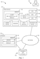
- Figure 1 is a diagram of an example MR contextual application (app) system 100 and associated devices configured to provide MR contextual application functionality to a user 102.
- the MR contextual app system 100 includes a user device 104 operated by the user 102 and a server 130 coupled in networked communication with the user device 104 via a network 150 (e.g., a cellular network, a Wi-Fi network, the Internet, and so forth).
- the user device 104 is a computing device capable of providing a mixed reality experience to the user 102.
- the user device 104 is a head-mounted display (HMD) device worn by the user 102, such as an augmented reality (AR) or virtual reality (VR) visor (e.g., Google Glass ® , HTC Vive ® , Microsoft HoloLens ® , and so forth).
- HMD head-mounted display
- AR augmented reality
- VR virtual reality
- the user device 104 is a mobile computing device, such as a smartphone or a tablet computer.
- the user device 104 includes one or more central processing units (CPUs) 106, graphics processing units (GPUs) 108, and holographic processing units (HPUs) 110.
- the user device 104 also includes one or more networking devices 112 (e.g., wired or wireless network adapters) for communicating across the network 150.
- the user device 104 further includes one or more camera devices 114 which may be configured to capture digital video of the real world near the user 102 during operation.
- the user device 104 may also include one or more sensors 116, such as a global positioning system (GPS) receiver (e.g., for determining a GPS location of the user device 104), biometric sensors (e.g., for capturing biometric data of the user 102), motion or position sensors (e.g., for capturing position data of the user 102 or other objects), or an audio microphone (e.g., for capturing sound data).
- GPS global positioning system
- Some sensors 116 may be external to the user device 104, and may be configured to wirelessly communicate with the user device 104 (e.g., such as used in the Microsoft Kinect ® , Vive Tracker TM , MIT's Lidar sensor, or MIT's wireless emotion detector).
- the user device 104 also includes one or more input devices 118 such as, for example, a keyboard or keypad, mouse, pointing device, touchscreen, or hand-held device (e.g., hand motion tracking device).
- the user device 104 further includes one or more display devices 120, such as a touchscreen of a tablet or smartphone, or lenses or visor of a VR or AR HMD, which may be configured to display virtual objects to the user 102 in conjunction with a real-world view.
- the user device 104 also includes a memory 122 configured to store a client MR contextual app module ("client module”) 124.
- the server 130 includes a memory 132 storing a server MR contextual app module ("server module”) 134.
- client module client MR contextual app module
- server module server MR contextual app module
- the client MR contextual app module 124 and the server MR contextual app module 134 perform the various contextual app functionalities described herein. More specifically, in some embodiments, some functionality may be implemented within the client module 124 and other functionality may be implemented within the server module 134.
- the client module 124 executing on the user device 104 (e.g., an HMD), may be configured to capture data from the camera device 114 or sensors 116 to detect satisfaction of trigger conditions associated with an application trigger.
- the server module 134 may process the captured data to detect satisfaction of trigger conditions.
- the camera device 114 and sensors 116 capture data from the surrounding environment, such as video, audio, depth information, GPS location, and so forth.
- the client module 124 may be configured to analyze the sensor data directly, or analyze processed sensor data (e.g., a real-time list of detected and identified objects, object shape data, depth maps, and the like).
- the client module 124 may search for specific trigger conditions in the data including, for example, the presence of objects, locations, symbols, logos, images, sounds near the user device 104, or identifiers of specific physical objects or surfaces, including fiducial markers.
- each application trigger configuration includes one or more trigger conditions, application logic or interaction mechanics for how the application interacts with the user, and an asset bundle that may include, for example, 2D/3D visuals and audio that are displayed to the user to provide an MR experience.
- the application trigger configuration may be stored within the client module 124, or within the server 130 or database 140.
- trigger conditions may include time limitations (e.g., particular times of day, or an amount of relative time since a past event), position or location limitations (e.g., the user device 104 being within a particular location, or within a certain distance of a certain type of object, or detecting a particular object within a certain distance of another object or sound), or various combinations thereof.
- the MR system 100 Upon detection of the trigger conditions, the MR system 100 initiates a contextual application identified by the associated application trigger. For example, detection of a serial number on a coffee machine may trigger a coffee app, or detection of a marker on a table may activate a computer game.
- the MR system 100 may also include an app database 140, which may be configured to store contextual applications and associated data. Execution of such contextual applications may include creating and displaying virtual objects to the user 102 (e.g., in relation to associated real-world objects within the field of view of the user 102). These virtual objects may be associated with the contextual application, and user interaction with the virtual objects may cause further actions by the associated contextual application, as described in further detail below.
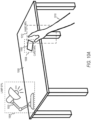
- FIG 2 is a diagram of an example HMD 220, worn by a user (or "wearer") 210, and configured to perform as the user device 104 of the MR system 100.
- the HMD 220 is similar to the user device 104, and may include any or all of the components of the user device 104, though not all are separately identified in Figure 2 .
- the HMD device 220 includes a transparent or semi-transparent visor (or "lens", or “lenses”) 222 through which the wearer 210 views their surroundings (also herein referred to also as "the real world").
- the HMD device 220 may include an opaque visor 222 which may obscure the wearer 210's view of the real world, but may present the wearer 210 a view of their surroundings via input from a digital camera device 230.
- the HMD 220 also includes a display device 228 that renders graphics (e.g., virtual objects) onto the visor 222.
- the visor 222 acts as a "screen" or surface on which the output of the display device 228 appears, and through which the wearer 210 experiences virtual content.
- the display device 228 is driven or controlled by one or more GPUs 226 or HPUs.
- the GPU 226 processes aspects of graphical output that assists in speeding up rendering of output through the display device 228.
- the visor 222 and display processor 228 may be similar to the display device 120 and the GPU 108 or HPU 110.
- the HMD device 220 also includes a central processor 224 that may execute some of the operations and methods described herein (e.g., executing the client module 124).
- the HMD device 220 also includes an audio device 250 that is configured to present audio output to the wearer 210 (e.g., via ears 216). While not separately shown, the HMD device 220 also includes a network device similar to the network device 112, and may communicate with the server 130 or app database 140 during operation.
- the HMD device 220 includes the digital camera device 230.
- the digital camera device (or just “camera”) 230 is a forward-facing video input device that is oriented so as to cover at least a portion of a field of view (FOV) of the wearer 210.
- FOV field of view
- the camera 230 captures or "sees” an angle of view of the real world based on the orientation of the HMD device 220 (e.g., similar to what the wearer 210 sees in the wearer 210's FOV when looking through the visor 222).
- the digital video from the camera device 230 may be analyzed to detect various trigger conditions, such as detecting types of objects near the wearer 210, or determining distance to those objects.
- output from the digital camera device 230 may be projected onto the visor 222 (e.g., in opaque visor embodiments), and may also include additional virtual content (e.g., added to the camera output).
- the HMD device 220 may include one or more sensors 116 (not separately shown in Figure 2 ), or may be coupled in wired or wireless communication with the sensors 112 (e.g., near-field communication (NFC) with a wrist-wearable device also worn by the wearer 210).
- the HMD 220 may include motion or position sensors configured to determine a position or orientation of the HMD 220.
- the HMD 220 is mounted over both eyes 214 of the wearer 210, as shown in Figure 2 .
- the client module 124 detects trigger conditions associated with various application triggers.
- the HMD 220 executes the associated contextual application.
- Some contextual applications may cause the HMD 220 to display additional virtual content (e.g., virtual objects) to the wearer 210, and may allow the wearer 210 to interact with those virtual objects. Such interactions may further engage the contextual application for additional functional processing associated with the virtual object.
- the HMD 220 provides contextual application functionality to the wearer 210 as the wearer 210 experiences a mixed reality environment.
- the HMD 220 may provide a fully-immersive VR environment.
- the MR system 100 detects virtual objects which may activate application triggers that cause presentation of contextual applications to the user 210 within the virtual environment when the contextual criteria are satisfied.
- the user 210 may be experiencing a virtual environment that includes a street and a series of shops and restaurants.
- the user 210 may pass a virtual Pizza Hut ® restaurant, whereby the client module 124 may detect the presence of the virtual restaurant, download a contextual application associated with the real Pizza Hut company, and provide the app to the user 210.
- the user 210 may then order a real pizza from the real restaurant through the contextual application presented within the virtual environment.
- the client module 124 continuously runs and communicates with the server 130, sending contextual data such as, for example, GPS coordinates, time of day, recognized objects in the environment, recognized fiducial markers (e.g., images), or raw video.
- the server 130 may include rules for optimizing performance in the client module 124 such as, for example, the client module 124 may be disabled from 3D object detection for a particular geographic area that does not contain MR apps that are triggered by physical objects.
- the client module 124 may operate as a contextual app launcher and scheduler, and thus may be referred to herein as an "MR operating system".
- the client module 124 may stream contextual apps' compressed packages (e.g., from the server 130), and decompress and run the app locally.
- the client module 124 executes the app's rules (e.g., scripts that define interaction and rendering rules) and renders audio and visual assets accordingly.
- the visual assets may be, for example, synthetic 3D models or 2D images that become virtual objects with which the user can potentially interact.
- Audio assets can be spatialized 3D sound effects or music, or mono sounds.
- haptic responses may also be initiated.
- the client module 124 may run more than one contextual app at the same time. For example, presume a coffee mug is in the user's view and it is 6pm. As such, one app may be triggered by the mug (e.g., displaying 3D animated particles around the mug and a dolphin jumping in and out of it), and another may be triggered by the current time (e.g., displaying a virtual TV screen playing the local news). The client module 124 schedules, starts, and stops the apps, and runs them simultaneously if applicable.
- Interaction rules define how the app responds to user actions.
- User actions may be, for example, voice commands, physical gestures (e.g., move arms or body, eye gaze movement, blinking, and so forth), interaction with the input devices 118 (e.g., controllers, 3D mouse, and so forth), or actions on an interactive display device 120.
- Responses to user actions may be, for example, modifying the rendered visuals (e.g., 2D/3D objects), audio, or haptic feedback.
- FIG 3 is a flowchart of an example method 300 for providing contextual applications to the user 102 as they experience an MR environment provided by the MR system 100.
- the user 102 wears the HMD 220 shown in Figure 2 as they move around a real-world environment (e.g., walking around in a room, or along a street).
- the various sensors 116 on the HMD 220 e.g., the camera device 230
- capture input data of that environment see operation 310.
- the client module 124 analyzes the input data to detect trigger conditions 302 of an application trigger (see operation 320).
- Trigger conditions 302 may be stored in and retrieved from the trigger and app database 140 prior to monitoring for the particular application trigger.
- One or more of the trigger conditions 302 involves detection of a particular type of real-world object within the environment.
- the client module 124 analyzes the camera video to detect a 3-dimensional (3D) object such as a chair or a box.
- operation 310 includes identifying 3D objects within the real-world environment to detect such trigger conditions 302.
- Operation 310 includes using artificial intelligence object recognition algorithms in order to identify objects within the user's environment. As 3D objects and other information about those objects (e.g., logos or information appearing on the objects, distance from the user 102) are identified, the object information for those 3D objects is compared with the trigger conditions 302 to detect whether all trigger conditions for the particular application trigger are met.
- the trigger conditions 302 of the application trigger may be pre-loaded onto the HMD 220 (e.g., a priori ) , and the client module 124 may be configured to detect those particular trigger conditions (e.g., at operation 320).
- various current conditions may be detected without pre-loading of the specific trigger conditions for the application trigger, and the MR system 100 may then determine that the current conditions match and satisfy the set of trigger conditions associated with the application trigger (e.g., a posteriori ) .
- the client module 124 When the client module 124 detects that the trigger conditions 302 for a particular application trigger are satisfied, then the client module 124 downloads app data of that application trigger (see operation 330) and initiates execution of the contextual application associated with that application trigger (see operation 340).
- the contextual application may identify visuals or sounds that may be presented relative to specific real-world object.
- executing the contextual application at operation 340 may include creating one or more virtual objects associated with the app and presenting those virtual objects to the user 102 within a MR environment (e.g., as depicted in Figures 5-10D ). Such virtual objects may be displayed relative to particular real-world objects (e.g., over or near one of the objects identified in the trigger conditions). Those virtual objects may be configured with various interactive actions (e.g., based on the app data 304), through which the user 102 may further activate functionality provided by the app.
- the client module 124 continues to detect trigger conditions while the app is running.
- additional application triggers may be loaded and/or detected, either independent of the active application trigger, or as an additional (e.g., nested) application trigger associated with the active trigger. For example, once a first trigger is activated (e.g., causing a first virtual object to be created and displayed), that parent application trigger may initiate monitoring for a second, child application trigger. In other words, the child application trigger may be configured to be monitored and detected only after the parent application trigger is activated.
- the client module 124 may adjust the execution of the app based on existing or changing trigger conditions.
- a "Carte Blanche app” may be active in a private reality layer and have trigger conditions of: GPS coordinates within the user 100's house and a volume that encompasses the house's extension, or perhaps only the living room.
- the interaction actions may include: (1) on startup, render a deck of cards on the surface of a table; (2) on startup, allow other users 100 to join, which may subsequently trigger a notification to nearby users 100 to join the session; (3) when any user 100 taps on any card (e.g., physically touches the table, or if the cards are hovering, then a finger detection on the location where the virtual card is displayed), animate the card flipping over; (4) when any user picks a card (e.g., executes a picking gesture with their hand on the location that the card is displayed), start moving the card to follow the user 100's hand; and (5) when any user performs a dropping gesture of dropping the card, render a virtual 3D object associated with the card and play a sound.
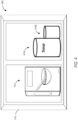
- Figure 4 illustrates an example real-world environment 400 that may be evaluated by the MR system 100.
- the real-world environment 400 includes a kitchen cabinet 410. Inside the kitchen cabinet are a box of cereal 412 and two cans of soup 414A, 414B.
- Figure 4 illustrates a front view of the kitchen cabinet 410.
- the user 102 may view the kitchen cabinet 410 and its contents as shown while operating the user device 104.
- the user 102 may be wearing the HMD 220.
- the user 102 may be holding a smartphone or tablet.
- the user device 104 collects sensor data from the real-world environment 400, such as digital video of the cabinet 410 and contents via the camera device 114.
- Figures 5 and 6 illustrate an MR environment 500 as presented to the user 102 by the MR system 100 via the user device 104.
- the user 102 wears the HMD 220 while viewing the real-world environment 400.
- the MR system 100 e.g., the client module 1234 presents various virtual objects within the MR environment 500. Accordingly, it should be understood that the MR environment 500 includes both a view of the real-world environment 400 and the various virtual objects.
- the MR environment 500 includes several recipe indicator objects 510A, 510B, 510C (collectively, objects 510).
- the objects 510 are virtual objects presented by the HMD 220, and appear as "stars" positioned over certain real-world objects with which they are affiliated (e.g., box of cereal 412 and cans of soup 414).
- the client module 124 captures input data from the HMD 220 in real time (e.g., digital video from the camera 230) and detects the presence of the three real-world objects 412, 414A, 414B (e.g., using 3D object detection techniques). Further, the client module 124 also determines that one of the cans of soup 414A is a can of mushroom soup (e.g., based on the shape of the object as a cylinder, and analysis of a label appearing on the can of soup 414A).
- the client module 124 searches the trigger & app database and determines that this type of object (e.g., canned good, can of mushroom soup, cooking ingredient) is associated with a particular contextual application (e.g., a recipe application). Further, the client module 124 may execute the contextual application to determine whether and how many recipes this particular cooking ingredient is associated with (e.g., based on the type of cooking ingredient, recipes involving mushroom soup).
- a particular contextual application e.g., a recipe application.
- the contextual application identifies three recipes involving the can of soup 414A.
- the client module 124 generates a virtual object 510B (e.g., a star object including the text "3 cards", representing the three recipes found by the app) and displays that virtual object 510B at the location of the associated real-world object (e.g., the can of soup 414A).
- a virtual object 510B e.g., a star object including the text "3 cards", representing the three recipes found by the app
- displays that virtual object 510B at the location of the associated real-world object e.g., the can of soup 414A.
- the MR system 100 determines the number of recipes associated with the box of cereal 412 and the other can of soup 414B, generates virtual objects 510A, 510C for those real-world objects 412, 414B, and displays those virtual objects 510A, 510C at the location of the associated real-world objects, respectively.
- the contextual app identifies one recipe associated with the box of cereal 412 and two recipes associated with the other can of soup 414B.
- each of the virtual objects 510 include one or more pre-defined interaction actions.
- Each interaction action identifies a user action (e.g., a hand gesture, a gaze focus) which, when taken by the user, causes a reciprocal application response (e.g., visual rendering, audio playback, haptic feedback).
- each recipe object 510 includes a "touch" interactive action that engages the contextual app to display associated recipes when the virtual object 510 is touched by a hand 502 of the user 102.
- the virtual objects 510 may be placed in a static location in 3D coordinate space (e.g., overlaid onto a real-world object), thereby causing the user 100 to have to touch or almost physically touch the object itself in order to activate any touching gestures associated with the virtual object 510.
- the virtual objects 510 may be positioned between the user 100 and the associated real-world object, and in line of sight with the real-world object such that the virtual object 510 looks to be "on" the physical object from the perspective of the user 100, but is instead within an arm's reach of the user 100 such that the user 100 can interact with the virtual object 510 without having to be within arm's reach of the real-world object.
- the virtual objects 510 may be repositioned to keep the virtual objects 510 in line with the real-world objects as viewed by the user 100.
- the user 102 touches the virtual object 510B associated with the can of soup 414A, thereby activating the display of recipes associated with mushroom soup.
- Figure 6 illustrates a reciprocal response to this touch action within the MR environment 500.
- the MR system 100 displays three recipe card objects 610A, 610B, 610C (collectively, recipe cards 610), one for each recipe identified by the contextual application.
- Each recipe card 610 is a virtual object, and may be displayed on or near the associated real-world object (e.g., can of soup 414A) or parent virtual object (e.g., recipe indicator object 510B).
- the recipe card object 610 may identify summary information about the underlying recipe, such as a title of the recipe, a cooking time, or other key ingredients needed, such that the user 102 can quickly see significant information about the recipe.
- each of the recipe card objects 610 may also include one or more interactive actions and associated reciprocal responses (e.g., that correspond to functions of the contextual application).
- Example reciprocal responses to interactive actions performed on the recipe card objects 610 include displaying detailed recipe information about the associated recipe (e.g., list of ingredients, cooking instructions, number of people served, preparation time, needed cooking appliances, dishes, and so forth), comparing the list of ingredients to a list of present ingredients to determine any missing ingredients (e.g., based on a current inventory, or based on other ingredients identified as nearby), or initiating step-by-step cooking instructions.
- the user 102 chooses the recipe card 610C, and the contextual application provides step-by-step cooking instructions to the user 102 via the MR system 100 and MR environment 500.
- the recipe card objects 610 may appear as virtual copies of the object itself (e.g., as cans of soup each denoting a different recipe), and the pre-defined interaction action involves the user utilizing the physical can (e.g., moving the can) to select from the objects 610.
- each recipe object 610 includes a "touch" interactive action that engages the contextual app to display associated recipes when the physical object of the can is placed in the same position and orientation as one of the virtual objects 610.
- the physical object of the can is used as a controller, and specifically in this case as a selector.
- the MR system 100 determines that the user 102 is in their home kitchen (e.g., based on GPS location, visual image recognition of the room, or based on real-world object detection of stove, refrigerator, and so forth). Further, the MR system 100 may similarly detect nearby real-world objects associated with the recipe, such as other cooking ingredients, appliances, dishes, pots, pans, or utensils identified by the recipe. The contextual application may identify and activate additional application triggers associated with such objects.
- the contextual application may include a set of steps or goals to accomplish over time.
- a contextual application may have three layers: a first layer may include trigger conditions that start the process; a second layer may include the goals to accomplish over time (e.g., via multiple nested contextual applications); and a third layer identifying completion (e.g., a set of completion criteria to terminate the parent contextual application).
- image based matching of the location surrounding the user is used to detect triggers.
- an entity such as a company with a physical presence at the location (e.g., a brick and mortar building or store) creates images of the location that are used in the image matching.
- the images (or any image matching information extracted from the images) created by the entity can be stored on a server as part of the trigger conditions 302 for use in the image matching during the process 320 of detecting trigger conditions.
- the images can include exterior images of a building or storefront, images from inside the building or storefront, and images of products within the store.
- the video data e.g., frames from the video
- the detecting trigger conditions 320 includes an artificial intelligence agent that completes the image matching process using artificial intelligence for image recognition/matching.
- the artificial intelligence includes application of machine-learning techniques for identifying three-dimensional objects in three-dimensional real-world environments (e.g., based on one or more attributes associated with the three-dimensional objects).
- the one or more attributes incorporated into the machine-learning techniques may include size, shape, color, texture, position, orientation, context (e.g., in relation to other virtual objects in the real-world environment), location (e.g., GPS or other location information), dimensions (e.g., height, width, and depth), and so on.
- the contextual application linked to a trigger can be configured to launch an advertisement or a game associated with that trigger.
- the application data 304 could include the advertisement data or game data.
- a company such as Starbucks Inc. and further consider a specific first coffee shop at a first location and a second coffee shop at a second location.
- An individual e.g., employee or contractor
- pictures of the first coffee shop e.g., inside, outside and product shots
- pictures of the second coffee shop e.g., inside, outside and product shots
- the user device 104 would collect video data of the exterior of the first coffee shop.
- the video data would be compared to the pictures (e.g., in the trigger conditions 302) of the first coffee shop and if a trigger was found, a contextual application (e.g., an advertisement) for the first coffee shop would execute on the device 104; perhaps offering the user points, or discounts contingent on the user entering the first coffee shop. Furthermore, if the user enters the first coffee shop, the user device 104 would collect video data of the interior of the first coffee shop thus confirming the user has entered and fulfilled a requirement (e.g., the requirement of entering the coffee shop) of the contextual application.
- a contextual application e.g., an advertisement
- the contextual app could continue to monitor the data from the user device 104 to detect further triggers based on the video data of the interior and further offer the user additional points, or discounts for merchandise within the store.
- user matching camera depth sensing information to a 3d model via a trained neural network is used to detect triggers.
- Figure 7 illustrates an example cooking pan 710 detected by the MR system 100 within the real-world environment 400.
- the example recipe activated as described above with respect to Figure 6 indicates the use of a pan in a "Step 1" of preparation instructions for the recipe.
- the contextual application may identify an application trigger involving detection of a pan object for "Step 1" of the preparation instructions.
- the pan 710 may, for example, be sitting out on a stove in the kitchen of the user 102 and, as such, may be recognized as a 3D object in the real-world environment 400 by the MR system 100.
- a cooking instruction for "Step 1" is initiated.
- the MR system 100 presents additional virtual objects associated with this cooking step and the pan 710 within the MR environment 500. More specifically, the MR system 100 displays a virtual timer 712 relative to the pan 710.
- the virtual timer 712 includes dial markers around a perimeter of the pan 712 (e.g., representing a 60-second minute, or a 60-minute hour) and one or more arms 716 at a center of the pan 712.
- Step 1 may identify pre-heating the pan 710 for 60 seconds, or may identify heating the mushroom soup in the pan 710 for 15 minutes on a low heat.
- the virtual timer 712 may be configured to count down or up based on the amount of time indicated, thereby providing a visual indication of the time called for by "Step 1", allowing the user 102 to track that step to completion.
- the MR system 100 continues to detect trigger conditions and interact with the user 102 until the user 102 dismisses the application or the contextual application is completed.
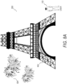
- Figures 8A and 8B illustrate two example layers offering different contextual applications.
- the MR system 100 presents an MR environment 800 that includes both real-world objects as well as virtual objects associated with a sponsor layer.
- the user 102 wears the HMD 220 while viewing the Eiffel Tower 802 (e.g., a real-world object in the environment 800).
- the sponsors of the Eiffel Tower e.g., the Council of Paris
- have created a contextual application associated with a tour application for the Eiffel Tower e.g., a tourist MR application
- the MR system 100 detects that the user 102 is viewing the Tower 802 (e.g., via image recognition, or based on geo-location and field of view of the user device 104). Further, the MR system 100 determines that the client module 124 is currently configured to present the sponsor layer, and that the sponsor layer includes a contextual application associated with the Eiffel Tower 802. As such, the MR system 100 creates and displays the virtual tour object 804 (e.g., fireworks) within the HMD 220 near the Tower 802, allowing the user 102 to activate the contextual application.
- the virtual tour object 804 e.g., fireworks
- the client module 124 is configured to present a user-generated layer.
- the user-generated layer may include contextual applications published by other users 102.
- a local artist may create a contextual application in which they make available an MR art work viewing for users 102 near the Tower 802, as represented by the virtual object 806.
- the MR system 100 determines that the client module 124 is currently configured to present the user-generated layer, and that the user-generated layer includes a contextual application associated with the Eiffel Tower 802 or that particular location. As such, the MR system 100 creates and displays the virtual object 806, allowing the user 102 to activate the associated user-generated contextual application.
- executing the contextual application at operation 340 includes morphing the displayed application to the physical dimensions of an object (e.g., a triggering object) in the user's 102 environment and using the real-time motion (e.g., physics) of the object to control aspects within the contextual application (e.g., to control the motion of a game character).
- the morphing includes detecting any of the type, shape, dimensions and motion of the object and adjusting the display of the contextual application to fit the size and orientation of the object as it moves within the environment.
- the motion includes the full three dimensions of rotation and three dimensions of translation.
- the client module 124 might detect the user is holding a rectangular cereal box that would act as a contextual trigger for either a specific game designed for that particular box, or a generic cereal box game that could be played on any cereal box.
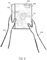
- Figure 9 is a first person perspective view of the environment showing an example wherein the user 102 is holding a cereal box 900 between his hands (902A and 902B).
- a static traditional maze game 904 e.g., one that is traditionally completed with a pencil
- the cereal box 900 acts as a trigger for a mixed reality game contextual application wherein the client module 124 displays a mixed reality version of the maze game on top of the static printed game version (the mixed reality version of the game is not separately shown in Figure 9 ).
- the client module 124 downloads (e.g., according to operation 330 described in relation to Figure 3 ) the application data and displays the game by morphing the game to the dimensions and orientation of the box in the user's hand using the detected shape, dimensions and orientation of the object.
- the client module 124 tracks the movement of the box 900 using any convenient method including object detection via the camera, or using a depth camera to track the object or using hand tracking information.
- the client module 124 takes the motion of the box 900 and applies the physics and behavior from the contextual application in order to generate the augmented reality display (e.g. virtual objects) that is placed on the back of the box 900.
- the detected movement of the box 900 is used to control a first character 906A traversing the maze.
- the client module 124 moves the game character 906A according to the character behavior programmed within the contextual application linked to the movement of the box 900.
- the exact movement of the box 900 with respect to all 6 degrees of freedom is used to move the first character 906A along the path in the game (and subsequently a second character 906B).
- Special movements of the box 900 can be used to cause specific actions for the character 906A such as starting movement of the character; also jerking the box 900 vertically can cause the character 906A to jump as it traverses the maze 904.
- dynamic instructions for the application can be displayed along with the display of the application.
- two dynamic animations 908A and 908B teach the user 102 how to move the box 900 in order to have a first character 906A move (shown in 908A) and jump (shown in 908B).
- the contextual application can be programmed such that it changes over time according to the application triggers.
- the application triggers can include the date, such that the game mechanics (e.g., the path of the maze, the type of maze, or the character skins/animations) changes each day; also, the type of game can change as well (e.g., from a maze game to a puzzle game).
- the game mechanics e.g., the path of the maze, the type of maze, or the character skins/animations
- the type of game can change as well (e.g., from a maze game to a puzzle game).
- a method for creating and using a deformable mesh controller that can be applied to an object of a specific type or shape (e.g., a cereal box, a soup can, a milk carton, a postcard, a business card, and more) in the environment surrounding the user.
- a deformable mesh controller is applied by the MR contextual app module 124 onto an object that has been detected (e.g., as a trigger) within the environment surrounding the user.
- the deformable mesh controller can have behaviors that are initiated and modified (e.g., controlled) by the movement and state of the object on which the deformable mesh controller is applied.
- the deformable mesh controller can be modified dynamically (e.g., while the MR contextual app module 124 is running) such that the size and shape of the deformable mesh controller is modified by the client module 124 and morphed to the exact size and shape of the object on which the deformable mesh controller is applied.
- the morphing (e.g., deforming) of the deformable mesh controller to the exact size and shape of the object is done using data that describes the object which comes from data that includes the sensor data from the HMD 220.
- An MR contextual application that is triggered by the object can use the deformable mesh controller applied to the object as a platform on which to display digital objects.
- a deformable mesh controller e.g., created by a video game developer
- generic controls for a cereal box game could be applied to any cereal box regardless of size and brand.
- a deformable mesh controller made for a cylindrical object such as a soup can could also be applied to a soft drink can.
- Process 320 from method 300 can include detecting at least one object which can serve as the controlling object on which the deformable mesh controller is applied by the module 124.
- Process 330 from method 300 can include downloading (e.g., over the network 150) deformable mesh controller data from a database 140.
- Process 340 from method 300 can include having the module 124 morph (e.g., deform) the deformable mesh controller to the exact size and shape of the controlling object.
- Process 350 from method 300 includes the module 124 monitoring the movement and orientation of the controlling object through time and moving the deformable mesh controller with it (e.g., attaching the deformable mesh controller to the object).
- Process 350 also includes monitoring the interaction of the user with the controlling object.
- the module 124 adjusts the execution of a triggered application based on the interactions.
- the contextual application is triggered by, and controlled by, a business card 1006 that is manipulated by a first person.
- the business card belongs to a second person and is a specific application trigger which triggers the server MR contextual app module 134 to send a specific application (e.g. related to the card and the second person) to the client MR contextual app module 124 for execution.
- the specific application is a mixed reality version of the LinkedIn TM application which has access to the LinkedIn TM data for the second person.
- the card is used (via an interaction with the first person) as a controller for the application.
- Specific interactions with the card which includes moving the card in specific directions and in specific ways as well as tapping the card and swiping on the card and gazing on the card is used to control the application.
- Some of the interactions can be determined with eye tracking technology and hand tracking technology.
- the interactions are used to initiate scrolling, selection, opening and closing controls within the application (e.g., for menus and features).
- the first person initiates the LinkedIn TM application by picking up the card.
- Figures 10A to 10D are shown from the perspective of the first person; for example, wearing and looking through a mixed reality HMD 220.
- the first person is standing in front of, and looking at a table 1000 with a lamp 1002 and a business card 1006 thereon.
- the hand 1010 of the first person is reaching for the card 1006.
- the client MR contextual app module 124 uses object recognition to detect at least the first person's hand 1010 and the business card 1006 of the second person.
- the MR contextual app module 124 displays dashed boxes around an object in order to confirm to the user that the object has been recognized.
- the dashed box might include a descriptive label and a confidence percentage for the recognized object.
- a dashed box 1012 is displayed around the hand 1010 of the user showing 98% confidence that the recognized object is a hand
- a dashed box 1004 is displayed around the lamp 1002 shows 97% confidence that the recognized object is a lamp
- a dashed box 1008 is shown around the card 1006 showing 94% confidence that the recognized object is a card.
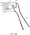
- Figure 10B shows the hand 1010 of the first person holding the card 1006 close enough to the user HMD 220 such that the MR contextual module 124 can recognize writing and images on the card 1006.
- the client MR contextual app module 124 uses instance segmentation to determine the company name 1020, username 1022 and contact details 1024 associated with the card 1006, and highlights the segments (e.g., perhaps with colored semi-transparent boxes 1014, 1016 and 1918).
- the MR contextual app module 124 determines (e.g., in accordance with process 320 described with respect to Figure 3 ) the card 1006 and the hand 1010 in proximity to each other (e.g., card 1006 being held by the hand 1010) as a trigger for a business card application.
- the MR contextual app module 124 would then download and execute data for the business card application (e.g., in accordance with process 330 and 340 in method 300 described in Figure 3 ).
- the card 1006 can be pitched (e.g., moved upward or downward with respect to the face of the card) in order to select options or open menus to be displayed in mixed reality using the HMD 220.
- Figure 10C shows the card 1006 as seen through the HMD 220 while the business card application is executing.
- the business card application executed by the MR contextual app module 124 uses diminished reality to erase (e.g., cover over) the contents on the card (e.g., the company name 1020, username 1022 and contact details 1024) and replace them with a digital display of the username 1022, a LinkedIn TM option link 1026, and a 'Connect' option link 1028 (e.g., which might link to a phone app to call the second person using the contact details 1024)
- the card shows a downward arrow with 'Connect' 1028 and an upward arrow with ⁇ LinkedIn profile' 1026.
- the MR contextual app module 124 continues to monitor the card 1006 and hand 1010 (e.g., as part of process 350 in method 300 described in Figure 3 ) in order to detect new triggers which would initiate responses by the business card application. For example, and as shown in Figure 10D , pitching the card upward (e.g., in a quick motion) can be recognized as a trigger within the business card application to connect with and display the LinkedIn TM account details 1030 of the second person; wherein the LinkedIn TM account details 1030 are shown to appear as popping out of the top of the card 1006 (e.g., as part of process 360 from method 300 as described with respect to Figure 3 ).. Other motions as described within the business card application would cause the MR contextual app module 124 to perform other actions.
- shaking the card up and down quickly can initiate a termination of the business card application causing a removal of all digitally displayed objects and a return to the real-world view of the card 1006.
- a downward motion might cause the HMD 220 to initiate a mobile phone call (e.g., if it is appropriately equipped) to the second person using the contact details 1024.
- diminished reality technology is used to visually clean surfaces and remove existing physical items from a user's view. Augmented reality technology is then used to add virtual objects to the user's view on top of the physical objects. For example, in Figure 9 , diminished reality can be used to clear the back of the cereal box in order to allow the dynamic virtual maze game to be displayed on the box.
- the MR system 100 may provide layered contextual applications to users 102. More specifically, the MR system 100 may provide various "reality layers" of contextual applications, where different users 102 may experience the same or different contextual applications in the same physical environment.
- a "shared layer” or "shared public feed”
- the shared layer may include content provided by "sponsors" (e.g., owners, custodians) of real-world locations may create MR contextual applications that are activated within their premise (e.g., the physical boundaries of a store or restaurant, geo-fenced area, within the range of a local Wi-Fi network, or within legal property boundaries).
- the shared layer may include user-sponsored content. As such, all users 102 may be allowed to experience contextual applications of various sponsors via the shared layer (e.g., as they visit particular locations, possibly as an opt-out or opt-in reality), and where the sponsors control the content presented.
- the MR system 100 may provide additional layers of contextual applications.
- the MR system 100 may allow users 102 to create and publish contextual applications within their own "private layer", or within a "user-generated layer” (e.g., containing user-generated content). As such, the user 102 may experience the private layer contextual applications instead of, or in addition to, contextual applications of other layers.
- the MR system 100 may allow sponsors to provide tiered layers of contextual applications.
- a particular sponsor may provide a "public layer” for everyone visiting their location (e.g., as described above), and may also provide an "employee layer” or a “members only layer” that is experienced only by employees or members of the sponsor (e.g., based on subscription to a service, or based on purchased content).
- multiple layers may be experienced simultaneously.
- the MR system 100 may provide both a shared layer's content and the user's own private layer content to the user at a given location simultaneously.
- the MR system 100 may present the user 102 with a selection of layers available to the user 102 at a particular location, or at a particular time.
- Modules may constitute either software modules (e.g., code embodied on a machine-readable medium) or hardware modules.
- a "hardware module” is a tangible unit capable of performing certain operations and may be configured or arranged in a certain physical manner.
- one or more computer systems e.g., a standalone computer system, a client computer system, or a server computer system
- one or more hardware modules of a computer system e.g., a processor or a group of processors
- software e.g., an application or application portion
- a hardware module may be implemented mechanically, electronically, or any suitable combination thereof.
- a hardware module may include dedicated circuitry or logic that is permanently configured to perform certain operations.
- a hardware module may be a special-purpose processor, such as a Field-Programmable Gate Array (FPGA) or an Application Specific Integrated Circuit (ASIC).
- a hardware module may also include programmable logic or circuitry that is temporarily configured by software to perform certain operations.
- a hardware module may include software executed by a general-purpose processor or other programmable processor. Once configured by such software, hardware modules become specific machines (or specific components of a machine) uniquely tailored to perform the configured functions and are no longer general-purpose processors. It will be appreciated that the decision to implement a hardware module mechanically, in dedicated and permanently configured circuitry, or in temporarily configured circuitry (e.g., configured by software) may be driven by cost and time considerations.
- hardware module should be understood to encompass a tangible entity, be that an entity that is physically constructed, permanently configured (e.g., hardwired), or temporarily configured (e.g., programmed) to operate in a certain manner or to perform certain operations described herein.
- “hardware-implemented module” refers to a hardware module. Considering embodiments in which hardware modules are temporarily configured (e.g., programmed), each of the hardware modules need not be configured or instantiated at any one instance in time. For example, where a hardware module comprises a general-purpose processor configured by software to become a special-purpose processor, the general-purpose processor may be configured as respectively different special-purpose processors (e.g., comprising different hardware modules) at different times. Software accordingly configures a particular processor or processors, for example, to constitute a particular hardware module at one instance of time and to constitute a different hardware module at a different instance of time.
- Hardware modules can provide information to, and receive information from, other hardware modules. Accordingly, the described hardware modules may be regarded as being communicatively coupled. Where multiple hardware modules exist contemporaneously, communications may be achieved through signal transmission (e.g., over appropriate circuits and buses) between or among two or more of the hardware modules. In embodiments in which multiple hardware modules are configured or instantiated at different times, communications between such hardware modules may be achieved, for example, through the storage and retrieval of information in memory structures to which the multiple hardware modules have access. For example, one hardware module may perform an operation and store the output of that operation in a memory device to which it is communicatively coupled. A further hardware module may then, at a later time, access the memory device to retrieve and process the stored output. Hardware modules may also initiate communications with input or output devices, and can operate on a resource (e.g., a collection of information).
- a resource e.g., a collection of information
- processors may be temporarily configured (e.g., by software) or permanently configured to perform the relevant operations. Whether temporarily or permanently configured, such processors may constitute processor-implemented modules that operate to perform one or more operations or functions described herein.
- processor-implemented module refers to a hardware module implemented using one or more processors.
- the methods described herein may be at least partially processor-implemented, with a particular processor or processors being an example of hardware.
- a particular processor or processors being an example of hardware.
- the operations of a method may be performed by one or more processors or processor-implemented modules.
- the one or more processors may also operate to support performance of the relevant operations in a "cloud computing" environment or as a "software as a service” (SaaS).
- SaaS software as a service
- at least some of the operations may be performed by a group of computers (as examples of machines including processors), with these operations being accessible via a network (e.g., the Internet) and via one or more appropriate interfaces (e.g., an Application Program Interface (API)).
- API Application Program Interface
- processors may be distributed among the processors, not only residing within a single machine, but deployed across a number of machines.
- the processors or processor-implemented modules may be located in a single geographic location (e.g., within a home environment, an office environment, or a server farm). In other example embodiments, the processors or processor-implemented modules may be distributed across a number of geographic locations.
- Software architectures are used in conjunction with hardware architectures to create devices and machines tailored to particular purposes. For example, a particular hardware architecture coupled with a particular software architecture will create a mobile device, such as a mobile phone, tablet device, or so forth. A slightly different hardware and software architecture may yield a smart device for use in the "internet of things.” While yet another combination produces a server computer for use within a cloud computing architecture. Not all combinations of such software and hardware architectures are presented here as those of skill in the art can readily understand how to implement the systems and methods described herein in different contexts from this disclosure.
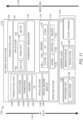
- Figure 11 is a block diagram 1100 illustrating a representative software architecture 1102, which may be used in conjunction with various hardware architectures described herein to provide the VR tools and development environment described herein.
- Figure 11 is merely a non-limiting example of a software architecture and it will be appreciated that many other architectures may be implemented to facilitate the functionality described herein.
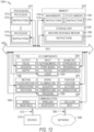
- the software architecture 1102 may be executing on hardware such as machine 1200 of Figure 12 that includes, among other things, processors 1210, memory 1230, and I/O components 1250.
- a representative hardware layer 1104 is illustrated and can represent, for example, the machine 1200 of Figure 12 .
- the representative hardware layer 1104 comprises one or more processing units 1106 having associated executable instructions 1108.
- Executable instructions 1108 represent the executable instructions of the software architecture 1102, including implementation of the methods, modules and so forth of Figures 1-10D .
- Hardware layer 1104 also includes memory or storage modules 1110, which also have executable instructions 1108.
- Hardware layer 904 may also comprise other hardware as indicated by 1112 which represents any other hardware of the hardware layer 1104, such as the other hardware illustrated as part of machine 1200.
- the software 1102 may be conceptualized as a stack of layers where each layer provides particular functionality.
- the software 1102 may include layers such as an operating system 1114, libraries 1116, frameworks/middleware 1118, applications 1120 and presentation layer 1122.
- the applications 1120 or other components within the layers may invoke application programming interface (API) calls 1124 through the software stack and receive a response, returned values, and so forth illustrated as messages 1126 in response to the API calls 1124.
- API application programming interface
- the layers illustrated are representative in nature and not all software architectures have all layers. For example, some mobile or special purpose operating systems may not provide a frameworks / middleware layer 918, while others may provide such a layer. Other software architectures may include additional or different layers.
- the operating system 1114 may manage hardware resources and provide common services.
- the operating system 1114 may include, for example, a kernel 1128, services 1130, and drivers 1132.
- the kernel 1128 may act as an abstraction layer between the hardware and the other software layers.
- the kernel 1128 may be responsible for memory management, processor management (e.g., scheduling), component management, networking, security settings, and so on.
- the services 1130 may provide other common services for the other software layers.
- the drivers 1132 may be responsible for controlling or interfacing with the underlying hardware.
- the drivers 1132 may include display drivers, camera drivers, Bluetooth ® drivers, flash memory drivers, serial communication drivers (e.g., Universal Serial Bus (USB) drivers), Wi-Fi ® drivers, audio drivers, power management drivers, and so forth depending on the hardware configuration.
- USB Universal Serial Bus
- the libraries 1116 may provide a common infrastructure that may be utilized by the applications 1120 or other components or layers.
- the libraries 1116 typically provide functionality that allows other software modules to perform tasks in an easier fashion than to interface directly with the underlying operating system 1114 functionality (e.g., kernel 1128, services 1130 or drivers 1132).
- the libraries 916 may include system 1134 libraries (e.g., C standard library) that may provide functions such as memory allocation functions, string manipulation functions, mathematic functions, and the like.
- libraries 1116 may include API libraries 1136 such as media libraries (e.g., libraries to support presentation and manipulation of various media format such as MPREG4, H.264, MP3, AAC, AMR, JPG, PNG), graphics libraries (e.g., an OpenGL framework that may be used to render 2D and 3D in a graphic content on a display), database libraries (e.g., SQLite that may provide various relational database functions), web libraries (e.g., WebKit that may provide web browsing functionality), and the like.
- the libraries 916 may also include a wide variety of other libraries 1138 to provide many other APIs to the applications 920 and other software components/modules.
- the frameworks 1118 may provide a higher-level common infrastructure that may be utilized by the applications 1120 or other software components/modules.
- the frameworks 1118 may provide various graphic user interface (GUI) functions, high-level resource management, high-level location services, and so forth.
- GUI graphic user interface
- the frameworks 1118 may provide a broad spectrum of other APIs that may be utilized by the applications 1120 or other software components/modules, some of which may be specific to a particular operating system or platform.
- the applications 1120 includes built-in applications 1140 or third-party applications 1142.
- built-in applications 940 may include, but are not limited to, a contacts application, a browser application, a book reader application, a location application, a media application, a messaging application, a MR application 1101, or a game application.
- Third party applications 1142 may include any of the built-in applications as well as a broad assortment of other applications.
- the third-party application 1142 e.g., an application developed using the Android TM or iOS TM software development kit (SDK) by an entity other than the vendor of the particular platform
- the third-party application 1142 may be mobile software running on a mobile operating system such as iOS TM , Android TM , Windows ® Phone, or other mobile operating systems.
- the third-party application 1142 may invoke the API calls 1124 provided by the mobile operating system such as operating system 1114 to facilitate functionality described herein.
- the applications 1120 may utilize built in operating system functions (e.g., kernel 1128, services 1130 or drivers 1132), libraries (e.g., system 1134, APIs 1136, and other libraries 1138), frameworks / middleware 1118 to create user interfaces to interact with users of the system. Alternatively, or additionally, in some systems interactions with a user may occur through a presentation layer, such as presentation layer 1144. In these systems, the application/module "logic" can be separated from the aspects of the application/module that interact with a user.
- virtual machine 1148 Some software architectures utilize virtual machines. In the example of Figure 11 , this is illustrated by virtual machine 1148.
- a virtual machine creates a software environment where applications/modules can execute as if they were executing on a hardware machine (such as the machine of Figure 12 , for example).
- a virtual machine is hosted by a host operating system (operating system 1114 in Figure 11 ) and typically, although not always, has a virtual machine monitor 1146, which manages the operation of the virtual machine as well as the interface with the host operating system (i.e., operating system 1114).
- a software architecture executes within the virtual machine such as an operating system 1150, libraries 1152, frameworks / middleware 1154, applications 1156 or presentation layer 1158. These layers of software architecture executing within the virtual machine 1148 can be the same as corresponding layers previously described or may be different.
- the MR application 1101 operates as an application in the applications 1120 layer. However, in some embodiments, the MR application 1101 may operate in other software layers, or in multiple software layers (e.g., framework 1118 and application 1120), or in any architecture that enables the systems and methods as described herein.
- the MR application 1101 may operate in other software layers, or in multiple software layers (e.g., framework 1118 and application 1120), or in any architecture that enables the systems and methods as described herein.
- Figure 12 is a block diagram illustrating components of a machine 1000, according to some example embodiments, able to read instructions from a machine-readable medium 1238 (e.g., a machine-readable storage medium) and perform any one or more of the VR methodologies discussed herein.
- Figure 12 shows a diagrammatic representation of the machine 1200 in the example form of a computer system, within which instructions 1216 (e.g., software, a software module, a program, an application, an applet, an app, or other executable code) for causing the machine 1200 to perform any one or more of the methodologies or operations discussed herein may be executed.
- the instructions may cause the machine to execute the one or more of the operations discussed with respect to Figure 3 .
- the instructions transform the general, non-programmed machine into a particular machine programmed to carry out the described and illustrated functions in the manner described.
- the machine 1200 operates as a standalone device or may be coupled (e.g., networked) to other machines.
- the machine 1200 may operate in the capacity of a server machine or a client machine in a server-client network environment, or as a peer machine in a peer-to-peer (or distributed) network environment.
- the machine 1200 may comprise, but not be limited to, a server computer, a client computer, a personal computer (PC), a tablet computer, a laptop computer, a netbook, a set-top box (STB), a personal digital assistant (PDA), an entertainment media system, a cellular telephone, a smart phone, a mobile device, a wearable device (e.g., a smart watch), a smart home device (e.g., a smart appliance), other smart devices, a web appliance, a network router, a network switch, a network bridge, or any machine capable of executing the instructions 1216, sequentially or otherwise, that specify actions to be taken by machine 1200.
- the term "machine” shall also be taken to include a collection of machines 1200 that individually or jointly execute the instructions 1216 to perform any one or more of the methodologies discussed herein.
- the machine 1200 may include processors 1210, memory 1230, and I/O components 1250, which may be configured to communicate with each other such as via a bus 1202.
- the processors 1210 e.g., a Central Processing Unit (CPU), a Reduced Instruction Set Computing (RISC) processor, a Complex Instruction Set Computing (CISC) processor, a Graphics Processing Unit (GPU), a Digital Signal Processor (DSP), an Application Specific Integrated Circuit (ASIC), a Radio-Frequency Integrated Circuit (RFIC), another processor, or any suitable combination thereof
- the processors 1210 may include, for example, processor 1212 and processor 1214 that may execute instructions 1216.
- processor is intended to include multi-core processor that may comprise two or more independent processors (sometimes referred to as "cores") that may execute instructions contemporaneously.
- Figure 12 shows multiple processors, the machine 1200 may include a single processor with a single core, a single processor with multiple cores (e.g., a multi-core process), multiple processors with a single core, multiple processors with multiples cores, or any combination thereof.
- the memory/storage 1230 may include a memory 1232, such as a main memory, or other memory storage, and a storage unit 1236, both accessible to the processors 1210 such as via the bus 1202.
- the storage unit 1236 and memory 1232 store the instructions 1216 embodying any one or more of the methodologies or functions described herein.
- the instructions 1216 may also reside, completely or partially, within the memory 1232, within the storage unit 1236, within at least one of the processors 1210 (e.g., within the processor's cache memory), or any suitable combination thereof, during execution thereof by the machine 1200. Accordingly, the memory 1232, the storage unit 1236, and the memory of processors 1210 are examples of machine-readable media.
- machine-readable medium means a device able to store instructions and data temporarily or permanently and may include, but is not be limited to, random-access memory (RAM), read-only memory (ROM), buffer memory, flash memory, optical media, magnetic media, cache memory, other types of storage (e.g., Erasable Programmable Read-Only Memory (EEPROM)) or any suitable combination thereof.
- RAM random-access memory
- ROM read-only memory
- buffer memory flash memory
- optical media magnetic media
- cache memory other types of storage
- EEPROM Erasable Programmable Read-Only Memory
- machine-readable medium shall also be taken to include any medium, or combination of multiple media, that is capable of storing instructions (e.g., instructions 1216) for execution by a machine (e.g., machine 1200), such that the instructions, when executed by one or more processors of the machine 1200 (e.g., processors 1210), cause the machine 1200 to perform any one or more of the methodologies described herein.
- a “machine-readable medium” refers to a single storage apparatus or device, as well as “cloud-based” storage systems or storage networks that include multiple storage apparatus or devices.
- the term “machine-readable medium” excludes transitory signals per se.
- the I/O components 1250 may include a wide variety of components to receive input, provide output, produce output, transmit information, exchange information, capture measurements, and so on.
- the specific I/O components 1250 that are included in a particular machine will depend on the type of machine. For example, portable machines such as mobile phones will likely include a touch input device or other such input mechanisms, while a headless server machine will likely not include such a touch input device. It will be appreciated that the I/O components 1250 may include many other components that are not shown in Figure 12 .
- the I/O components 1250 are grouped according to functionality merely for simplifying the following discussion and the grouping is in no way limiting. In various example embodiments, the I/O components 1250 may include output components 1252 and input components 1254.
- the output components 1252 may include visual components (e.g., displays such as a plasma display panel (PDP), a light emitting diode (LED) display, a liquid crystal display (LCD), a projector, a cathode ray tube (CRT), or wearable devices such as head-mounted display (HMD) devices), acoustic components (e.g., speakers), haptic components (e.g., a vibratory motor, resistance mechanisms), other signal generators, and so forth.
- visual components e.g., displays such as a plasma display panel (PDP), a light emitting diode (LED) display, a liquid crystal display (LCD), a projector, a cathode ray tube (CRT), or wearable devices such as head-mounted display (HMD) devices
- acoustic components e.g., speakers
- haptic components e.g., a vibratory motor, resistance mechanisms
- the input components 1254 may include alphanumeric input components (e.g., a keyboard, a touch screen configured to receive alphanumeric input, a photo-optical keyboard, or other alphanumeric input components), point based input components (e.g., a mouse, a touchpad, a trackball, a joystick, a motion sensor, or other pointing instrument), tactile input components (e.g., a physical button, a touch screen that provides location or force of touches or touch gestures, or other tactile input components), motion-sensing input components (e.g., hand controllers), audio input components (e.g., a microphone), and the like.
- alphanumeric input components e.g., a keyboard, a touch screen configured to receive alphanumeric input, a photo-optical keyboard, or other alphanumeric input components
- point based input components e.g., a mouse, a touchpad, a trackball, a joystick, a motion sensor, or other pointing instrument
- the I/O components 1250 may include biometric components 1256, motion components 1258, environmental components 1260, or position components 1262 among a wide array of other components.
- the biometric components 1256 may include components to detect expressions (e.g., hand expressions, facial expressions, vocal expressions, body gestures, or eye tracking), measure biosignals (e.g., blood pressure, heart rate, body temperature, perspiration, or brain waves), identify a person (e.g., voice identification, retinal identification, facial identification, fingerprint identification, or electroencephalogram based identification), and the like.
- the motion components 1258 may include acceleration sensor components (e.g., accelerometer), gravitation sensor components, rotation sensor components (e.g., gyroscope), position-sensing components, and so forth.
- the environmental components 1260 may include, for example, illumination sensor components (e.g., photometer), temperature sensor components (e.g., one or more thermometer that detect ambient temperature), humidity sensor components, pressure sensor components (e.g., barometer), acoustic sensor components (e.g., one or more microphones that detect background noise), proximity sensor components (e.g., infrared sensors that detect nearby objects), gas sensors (e.g., gas detection sensors to detection concentrations of hazardous gases for safety or to measure pollutants in the atmosphere), or other components that may provide indications, measurements, or signals corresponding to a surrounding physical environment.
- illumination sensor components e.g., photometer
- temperature sensor components e.g., one or more thermometer that detect ambient temperature
- humidity sensor components e.g., pressure sensor components (e.
- the position components 1262 may include location sensor components (e.g., a Global Position System (GPS) receiver component), altitude sensor components (e.g., altimeters or barometers that detect air pressure from which altitude may be derived), orientation sensor components (e.g., magnetometers), and the like.
- location sensor components e.g., a Global Position System (GPS) receiver component
- altitude sensor components e.g., altimeters or barometers that detect air pressure from which altitude may be derived
- orientation sensor components e.g., magnetometers
- the I/O components 1250 may include communication components 1264 operable to couple the machine 1200 to a network 1280 or devices 1270 via coupling 1282 and coupling 1272 respectively.
- the communication components 1264 may include a network interface component or other suitable device to interface with the network 1280.
- communication components 1264 may include wired communication components, wireless communication components, cellular communication components, Near Field Communication (NFC) components, Bluetooth ® components (e.g., Bluetooth ® Low Energy), Wi-Fi ® components, and other communication components to provide communication via other modalities.
- the devices 1270 may be another machine or any of a wide variety of peripheral devices (e.g., a peripheral device coupled via a Universal Serial Bus (USB)).
- USB Universal Serial Bus
- one or more portions of the network 1080 may be an ad hoc network, an intranet, an extranet, a virtual private network (VPN), a local area network (LAN), a wireless LAN (WLAN), a wide area network (WAN), a wireless WAN (WWAN), a metropolitan area network (MAN), the Internet, a portion of the Internet, a portion of the Public Switched Telephone Network (PSTN), a plain old telephone service (POTS) network, a cellular telephone network, a wireless network, a Wi-Fi ® network, another type of network, or a combination of two or more such networks.
- VPN virtual private network
- LAN local area network
- WLAN wireless LAN
- WAN wide area network
- WWAN wireless WAN
- MAN metropolitan area network
- PSTN Public Switched Telephone Network
- POTS plain old telephone service
- the network 1280 or a portion of the network 1280 may include a wireless or cellular network and the coupling 1282 may be a Code Division Multiple Access (CDMA) connection, a Global System for Mobile communications (GSM) connection, or other type of cellular or wireless coupling.
- CDMA Code Division Multiple Access
- GSM Global System for Mobile communications
- the coupling 1282 may implement any of a variety of types of data transfer technology, such as Single Carrier Radio Transmission Technology (1xRTT), Evolution-Data Optimized (EVDO) technology, General Packet Radio Service (GPRS) technology, Enhanced Data rates for GSM Evolution (EDGE) technology, third Generation Partnership Project (3GPP) including 3G, fourth generation wireless (4G) networks, Universal Mobile Telecommunications System (UMTS), High Speed Packet Access (HSPA), Worldwide Interoperability for Microwave Access (WiMAX), Long Term Evolution (LTE) standard, others defined by various standard setting organizations, other long range protocols, or other data transfer technology.
- 1xRTT Single Carrier Radio Transmission Technology
- GPRS General Packet Radio Service
- EDGE Enhanced Data rates for GSM Evolution
- 3GPP Third Generation Partnership Project
- 4G fourth generation wireless (4G) networks
- Universal Mobile Telecommunications System (UMTS) Universal Mobile Telecommunications System
- HSPA High Speed Packet Access
- WiMAX Worldwide Interoperability for Microwave Access
- the instructions 1216 may be transmitted or received over the network 1280 using a transmission medium via a network interface device (e.g., a network interface component included in the communication components 1264) and utilizing any one of a number of transfer protocols (e.g., hypertext transfer protocol (HTTP)). Similarly, the instructions 1216 may be transmitted or received using a transmission medium via the coupling 1272 (e.g., a peer-to-peer coupling) to devices 1270.
- the term "transmission medium” shall be taken to include any intangible medium that is capable of storing, encoding, or carrying instructions 1216 for execution by the machine 1200, and includes digital or analog communications signals or other intangible medium to facilitate communication of such software.
- inventive subject matter has been described with reference to specific example embodiments, various modifications and changes may be made to these embodiments without departing from the broader scope of embodiments of the present disclosure.
- inventive subject matter may be referred to herein, individually or collectively, by the term "invention" merely for convenience and without intending to voluntarily limit the scope of this application to any single disclosure or inventive concept if more than one is, in fact, disclosed.
- the term "or" may be construed in either an inclusive or exclusive sense. Moreover, plural instances may be provided for resources, operations, or structures described herein as a single instance. Additionally, boundaries between various resources, operations, modules, engines, and data stores are somewhat arbitrary, and particular operations are illustrated in a context of specific illustrative configurations. Other allocations of functionality are envisioned and may fall within a scope of various embodiments of the present disclosure. In general, structures and functionality presented as separate resources in the example configurations may be implemented as a combined structure or resource. Similarly, structures and functionality presented as a single resource may be implemented as separate resources. These and other variations, modifications, additions, and improvements fall within a scope of embodiments of the present disclosure as represented by the appended claims. The specification and drawings are, accordingly, to be regarded in an illustrative rather than a restrictive sense.
Landscapes
- Engineering & Computer Science (AREA)
- Physics & Mathematics (AREA)
- Theoretical Computer Science (AREA)
- General Engineering & Computer Science (AREA)
- General Physics & Mathematics (AREA)
- Human Computer Interaction (AREA)
- Optics & Photonics (AREA)
- Computer Graphics (AREA)
- Computer Hardware Design (AREA)
- Software Systems (AREA)
- Multimedia (AREA)
- User Interface Of Digital Computer (AREA)
- Processing Or Creating Images (AREA)
- Controls And Circuits For Display Device (AREA)
- Image Analysis (AREA)
Claims (13)
- Un système pour mettre en oeuvre une pluralité d'applications contextuelles au sein d'un environnement de réalité mixte, MR, l'environnement de MR étant fourni sur un dispositif apte à la MR d'un utilisateur (104 ; 220), le système comprenant :un ou plusieurs processeurs d'ordinateur (106, 108, 110 ; 1210) ;une ou plusieurs mémoires d'ordinateur (122, 132 ; 1230) ; etun ensemble d'instructions incorporées dans ces une ou plusieurs mémoires d'ordinateur, l'ensemble d'instructions configurant ces un ou plusieurs processeurs d'ordinateur afin qu'ils effectuent des opérations comprenant :le fait d'effectuer une analyse de données en temps réel capturées par des détecteurs (114, 116) du dispositif apte à la MR correspondant à un environnement (400) entourant l'utilisateur, l'analyse étant effectuée par identification d'au moins un objet du monde réel dans l'environnement (400) par application d'un algorithme de reconnaissance d'objets sur un ou plusieurs attributs de cet au moins un objet du monde réel qui sont capturés par les détecteurs du dispositif apte à la MR ;le fait d'utiliser une première application contextuelle de la pluralité d'applications contextuelles afin de déterminer une association entre un premier ensemble de déclencheurs contextuels et une deuxième application contextuelle de la pluralité d'applications contextuelles, la première application contextuelle étant une application de lancement ;le fait de démarrer la deuxième application contextuelle sur la base d'une détermination du fait qu'au moins un déclencheur du premier ensemble de déclencheurs contextuels a été satisfait, la détermination du fait que cet au moins un déclencheur du premier ensemble de déclencheurs contextuels a été satisfait étant basée sur l'analyse de données en temps réel correspondant à l'environnement (400) entourant l'utilisateur, le démarrage incluant le fait de présenter au moins un objet virtuel qui est associé à la deuxième application contextuelle dans l'environnement de MR ; etle fait d'invoquer une fonction au sein de la deuxième application contextuelle sur la base d'une détermination du fait qu'une interaction de l'utilisateur avec cet au moins un objet virtuel satisfait à un deuxième ensemble de déclencheurs contextuels, le deuxième ensemble de déclencheurs contextuels étant associé à la deuxième application contextuelle, la détermination du fait que l'interaction de l'utilisateur avec cet au moins un objet virtuel satisfait au deuxième ensemble de déclencheurs contextuels étant basée sur des règles d'interaction définies par la deuxième application contextuelle,dans lequel le fait d'appliquer l'algorithme de reconnaissance d'objets inclut le fait d'utiliser une intelligence artificielle afin d'effectuer l'identification de cet au moins un objet du monde réel dans l'environnement.
- Le système de la revendication 1, dans lequel la deuxième application contextuelle a au moins une couche d'affichage partagée, la couche d'affichage partagée étant configurée pour fournir une expérience d'un environnement physique partagé à une pluralité d'utilisateurs différents de la deuxième application contextuelle, et dans lequel la présentation de cet au moins un objet virtuel par la deuxième application contextuelle est basée sur une correspondance entre l'utilisateur et la couche d'affichage partagée associée à la deuxième application contextuelle passant sur un deuxième dispositif apte à la MR.
- Le système de la revendication 1, dans lequel l'interaction de l'utilisateur inclut le fait d'utiliser cet au moins un objet du monde réel en tant que dispositif de commande.
- Le système de la revendication 1, dans lequel le démarrage de la deuxième application contextuelle inclut le fait d'effacer des parties de cet au moins un objet du monde réel d'un affichage préalablement au fait de modifier une représentation de cet au moins un objet du monde réel sur le dispositif apte à la MR.
- Le système de la revendication 3, dans lequel l'utilisation de cet au moins un objet du monde réel en tant que dispositif de commande inclut le fait de manipuler l'objet du monde réel en trois dimensions afin de commander une action au sein de la deuxième application contextuelle, l'action étant définie en utilisant une interface de programme d'application de la deuxième application contextuelle.
- Le système de la revendication 1, dans lequel le premier ensemble de déclencheurs contextuels inclut une combinaison d'éléments incluant au moins deux données parmi des données relatives à un moment de l'identification, des données relatives à un emplacement du dispositif de MR, et des données relatives à un ensemble d'objets du monde réel additionnels identifiés dans l'environnement de MR.
- Un procédé pour mettre en oeuvre une pluralité d'applications contextuelles au sein d'un environnement de réalité mixte, MR, l'environnement de MR étant fourni sur un dispositif apte à la MR d'un utilisateur, le procédé comprenant :le fait d'effectuer une analyse de données en temps réel capturées par des détecteurs (114, 116) du dispositif apte à la MR correspondant à un environnement (400) entourant l'utilisateur, l'analyse étant effectuée par identification d'au moins un objet du monde réel dans l'environnement par application d'un algorithme de reconnaissance d'objets sur un ou plusieurs attributs de cet au moins un objet du monde réel qui sont capturés (310) par les détecteurs du dispositif apte à la MR ;le fait d'utiliser une première application contextuelle de la pluralité d'applications contextuelles afin de déterminer (320) une association entre un premier ensemble de déclencheurs contextuels et une deuxième application contextuelle de la pluralité d'applications contextuelles, la première application contextuelle étant une application de lancement ;le fait de démarrer (340) la deuxième application contextuelle sur la base d'une détermination du fait qu'au moins un déclencheur du premier ensemble de déclencheurs contextuels a été satisfait, la détermination du fait que cet au moins un déclencheur du premier ensemble de déclencheurs contextuels a été satisfait étant basée sur l'analyse de données en temps réel correspondant à l'environnement entourant l'utilisateur, le démarrage incluant le fait de présenter au moins un objet virtuel qui est associé à la deuxième application contextuelle dans l'environnement de MR; etle fait d'invoquer (360) une fonction au sein de la deuxième application contextuelle sur la base d'une détermination (350) du fait qu'une interaction de l'utilisateur avec cet au moins un objet virtuel satisfait à un deuxième ensemble de déclencheurs contextuels, le deuxième ensemble de déclencheurs contextuels étant associé à la deuxième application contextuelle, la détermination du fait que l'interaction de l'utilisateur avec cet au moins un objet virtuel satisfait au deuxième ensemble de déclencheurs contextuels étant basée sur des règles d'interaction définies par la deuxième application contextuelle,dans lequel le fait d'appliquer l'algorithme de reconnaissance d'objets inclut le fait d'utiliser une intelligence artificielle afin d'effectuer l'identification de cet au moins un objet du monde réel dans l'environnement.
- Le procédé de la revendication 7, dans lequel la deuxième application contextuelle a au moins une couche d'affichage partagée, la couche d'affichage partagée étant configurée pour fournir une expérience d'un environnement physique partagé à une pluralité d'utilisateurs différents de la deuxième application contextuelle, et dans lequel la présentation de l'au moins un objet virtuel par la deuxième application contextuelle est basée sur une correspondance entre l'utilisateur et la couche d'affichage partagée associée à la deuxième application contextuelle s'exécutant sur un deuxième dispositif apte à la MR.
- Le procédé de la revendication 7, dans lequel l'interaction de l'utilisateur inclut le fait d'utiliser cet au moins un objet du monde réel en tant que dispositif de commande.
- Le procédé de la revendication 7, dans lequel le démarrage de la deuxième application contextuelle inclut le fait d'effacer des parties de cet au moins un objet du monde réel d'un affichage préalablement au fait de modifier une représentation de cet au moins un objet du monde réel sur le dispositif apte à la MR.
- Le procédé de la revendication 9, dans lequel l'utilisation de cet au moins un objet du monde réel en tant que dispositif de commande inclut le fait de manipuler l'objet du monde réel en trois dimensions afin de commander une action au sein de la deuxième application contextuelle, l'action étant définie en utilisant une interface de programme d'application de la deuxième application contextuelle.
- Le procédé de la revendication 7, dans lequel le premier ensemble de déclencheurs contextuels inclut une combinaison d'éléments incluant au moins deux données parmi des données relatives à un moment de l'identification, des données relatives à un emplacement du dispositif de MR, et des données relatives à un ensemble d'objets du monde réel additionnels identifiés dans l'environnement de MR.
- Un support lisible par machine mettant en oeuvre le procédé de n'importe laquelle des revendications 7 à 12.
Applications Claiming Priority (3)
| Application Number | Priority Date | Filing Date | Title |
|---|---|---|---|
| US201762502349P | 2017-05-05 | 2017-05-05 | |
| US201762561017P | 2017-09-20 | 2017-09-20 | |
| PCT/US2018/031245 WO2018204879A1 (fr) | 2017-05-05 | 2018-05-04 | Applications contextuelles dans un environnement de réalité mixte |
Publications (3)
| Publication Number | Publication Date |
|---|---|
| EP3639261A1 EP3639261A1 (fr) | 2020-04-22 |
| EP3639261A4 EP3639261A4 (fr) | 2020-05-13 |
| EP3639261B1 true EP3639261B1 (fr) | 2023-08-30 |
Family
ID=64014833
Family Applications (1)
| Application Number | Title | Priority Date | Filing Date |
|---|---|---|---|
| EP18794296.6A Active EP3639261B1 (fr) | 2017-05-05 | 2018-05-04 | Applications contextuelles dans un environnement de réalité mixte |
Country Status (7)
| Country | Link |
|---|---|
| US (3) | US10360734B2 (fr) |
| EP (1) | EP3639261B1 (fr) |
| JP (1) | JP6828189B2 (fr) |
| KR (1) | KR102220949B1 (fr) |
| CN (1) | CN111033605A (fr) |
| CA (1) | CA3062541C (fr) |
| WO (1) | WO2018204879A1 (fr) |
Families Citing this family (44)
| Publication number | Priority date | Publication date | Assignee | Title |
|---|---|---|---|---|
| CN104740869B (zh) * | 2015-03-26 | 2018-04-03 | 北京小小牛创意科技有限公司 | 一种融合真实环境的虚实结合的交互方法及系统 |
| JP2018005091A (ja) * | 2016-07-06 | 2018-01-11 | 富士通株式会社 | 表示制御プログラム、表示制御方法および表示制御装置 |
| US10867445B1 (en) * | 2016-11-16 | 2020-12-15 | Amazon Technologies, Inc. | Content segmentation and navigation |
| WO2018204879A1 (fr) | 2017-05-05 | 2018-11-08 | Unity IPR ApS | Applications contextuelles dans un environnement de réalité mixte |
| US10559133B2 (en) * | 2018-02-07 | 2020-02-11 | Dell Products L.P. | Visual space management across information handling system and augmented reality |
| CN108769814B (zh) * | 2018-06-01 | 2022-02-01 | 腾讯科技(深圳)有限公司 | 视频互动方法、装置、终端及可读存储介质 |
| US11195336B2 (en) | 2018-06-08 | 2021-12-07 | Vulcan Inc. | Framework for augmented reality applications |
| US20190385372A1 (en) * | 2018-06-15 | 2019-12-19 | Microsoft Technology Licensing, Llc | Positioning a virtual reality passthrough region at a known distance |
| US10635895B2 (en) | 2018-06-27 | 2020-04-28 | Facebook Technologies, Llc | Gesture-based casting and manipulation of virtual content in artificial-reality environments |
| US10712901B2 (en) | 2018-06-27 | 2020-07-14 | Facebook Technologies, Llc | Gesture-based content sharing in artificial reality environments |
| US10783712B2 (en) * | 2018-06-27 | 2020-09-22 | Facebook Technologies, Llc | Visual flairs for emphasizing gestures in artificial-reality environments |
| US10996831B2 (en) | 2018-06-29 | 2021-05-04 | Vulcan Inc. | Augmented reality cursors |
| CN113272766A (zh) | 2019-01-24 | 2021-08-17 | 麦克赛尔株式会社 | 显示终端、应用程序控制系统和应用程序控制方法 |
| US11054896B1 (en) * | 2019-02-07 | 2021-07-06 | Facebook, Inc. | Displaying virtual interaction objects to a user on a reference plane |
| US11836978B2 (en) * | 2019-03-08 | 2023-12-05 | Ntt Docomo, Inc. | Related information output device |
| US10810782B1 (en) * | 2019-04-01 | 2020-10-20 | Snap Inc. | Semantic texture mapping system |
| US11804014B1 (en) * | 2019-04-22 | 2023-10-31 | Apple Inc. | Context-based application placement |
| US11163997B2 (en) * | 2019-05-05 | 2021-11-02 | Google Llc | Methods and apparatus for venue based augmented reality |
| US10897564B1 (en) | 2019-06-17 | 2021-01-19 | Snap Inc. | Shared control of camera device by multiple devices |
| JPWO2020261028A1 (fr) * | 2019-06-25 | 2020-12-30 | ||
| US11100715B2 (en) * | 2019-06-26 | 2021-08-24 | International Business Machines Corporation | Establishment of positional timers in an augmented reality environment |
| US11340857B1 (en) | 2019-07-19 | 2022-05-24 | Snap Inc. | Shared control of a virtual object by multiple devices |
| US11176744B2 (en) * | 2019-07-22 | 2021-11-16 | Microsoft Technology Licensing, Llc | Mapping sensor data using a mixed-reality cloud |
| US11461867B2 (en) * | 2019-09-19 | 2022-10-04 | Sanctuary Cognitive Systems Corporation | Visual interface and communications techniques for use with robots |
| CN110716645A (zh) * | 2019-10-15 | 2020-01-21 | 北京市商汤科技开发有限公司 | 一种增强现实数据呈现方法、装置、电子设备及存储介质 |
| US11270115B2 (en) * | 2019-11-18 | 2022-03-08 | Lenovo (Singapore) Pte. Ltd. | Presentation of augmented reality content based on identification of trigger accompanying video content |
| US11461115B2 (en) * | 2020-01-28 | 2022-10-04 | Sap Se | Third party executable asset bundle deployment |
| US11354867B2 (en) * | 2020-03-04 | 2022-06-07 | Apple Inc. | Environment application model |
| US11985175B2 (en) | 2020-03-25 | 2024-05-14 | Snap Inc. | Virtual interaction session to facilitate time limited augmented reality based communication between multiple users |
| US11593997B2 (en) * | 2020-03-31 | 2023-02-28 | Snap Inc. | Context based augmented reality communication |
| CN111462663B (zh) * | 2020-06-19 | 2020-10-27 | 南京新研协同定位导航研究院有限公司 | 一种基于mr眼镜的导游方法 |
| CN111539662A (zh) * | 2020-07-10 | 2020-08-14 | 南京新研协同定位导航研究院有限公司 | 基于mr眼镜租赁业务的动态库存分配方法 |
| US11617953B2 (en) | 2020-10-09 | 2023-04-04 | Contact Control Interfaces, Llc. | Virtual object interaction scripts |
| EP3995191A1 (fr) * | 2020-11-04 | 2022-05-11 | Unity IPR APS | Procédé et système permettant de fusionner des espaces distants |
| JP6975489B1 (ja) * | 2020-12-18 | 2021-12-01 | 株式会社Gatari | 情報処理システム、情報処理方法および情報処理プログラム |
| KR20220121990A (ko) * | 2021-02-26 | 2022-09-02 | 삼성전자주식회사 | 증강 현실 장치 및 증강 현실 장치와 상호작용하는 전자 장치 |
| BR112023018456A2 (pt) * | 2021-03-12 | 2023-10-10 | Christopher faraguna | Sistemas e métodos para coleta de dados de usuários dentro de um jogo de realidade aumentada |
| US11935199B2 (en) * | 2021-07-26 | 2024-03-19 | Google Llc | Augmented reality depth detection through object recognition |
| US20230066686A1 (en) * | 2021-09-02 | 2023-03-02 | Snap Inc. | Augmented reality prop interactions |
| US11969650B2 (en) | 2021-11-18 | 2024-04-30 | Sony Interactive Entertainment Inc. | Feature similarity scoring of physical environment for augmented reality gameplay |
| US11568616B1 (en) * | 2021-11-29 | 2023-01-31 | Varjo Technologies Oy | Display apparatuses and methods for facilitating location-based virtual content |
| CN114971764A (zh) * | 2022-04-08 | 2022-08-30 | 浙江赟燊商业信息系统科技有限公司 | 一种基于HoloLens的存储和匹配系统及方法 |
| JP7482943B2 (ja) | 2022-06-17 | 2024-05-14 | ソフトバンク株式会社 | 情報処理装置、プログラム、システム、及び情報処理方法 |
| US20240037863A1 (en) * | 2022-07-29 | 2024-02-01 | Maplebear Inc. (Dba Instacart) | Displaying an augmented reality element that provides a personalized enhanced experience at a warehouse |
Family Cites Families (14)
| Publication number | Priority date | Publication date | Assignee | Title |
|---|---|---|---|---|
| US20110213664A1 (en) * | 2010-02-28 | 2011-09-01 | Osterhout Group, Inc. | Local advertising content on an interactive head-mounted eyepiece |
| US9285589B2 (en) * | 2010-02-28 | 2016-03-15 | Microsoft Technology Licensing, Llc | AR glasses with event and sensor triggered control of AR eyepiece applications |
| JP2013004001A (ja) * | 2011-06-21 | 2013-01-07 | Sony Corp | 表示制御装置、表示制御方法、およびプログラム |
| US10019962B2 (en) * | 2011-08-17 | 2018-07-10 | Microsoft Technology Licensing, Llc | Context adaptive user interface for augmented reality display |
| KR101874895B1 (ko) * | 2012-01-12 | 2018-07-06 | 삼성전자 주식회사 | 증강 현실 제공 방법 및 이를 지원하는 단말기 |
| GB2501929B (en) * | 2012-05-11 | 2015-06-24 | Sony Comp Entertainment Europe | Apparatus and method for augmented reality |
| KR102062763B1 (ko) * | 2012-12-07 | 2020-01-07 | 삼성전자주식회사 | 상황 정보 기반의 정보 제공 방법 및 시스템과 그 기록 매체 |
| US9924102B2 (en) * | 2013-03-14 | 2018-03-20 | Qualcomm Incorporated | Image-based application launcher |
| US9240075B2 (en) * | 2013-03-15 | 2016-01-19 | Daqri, Llc | Campaign optimization for experience content dataset |
| CN203250508U (zh) * | 2013-04-24 | 2013-10-23 | 苏州创捷传媒展览股份有限公司 | 3d混合现实展示装置 |
| US10025375B2 (en) * | 2015-10-01 | 2018-07-17 | Disney Enterprises, Inc. | Augmented reality controls for user interactions with a virtual world |
| US9536355B1 (en) * | 2016-03-24 | 2017-01-03 | Daqri, Llc | Thermal detection in an augmented reality system |
| CN105912130A (zh) * | 2016-07-06 | 2016-08-31 | 深圳云戈科技有限公司 | 一种基于混合现实的通信方法、装置及系统 |
| WO2018204879A1 (fr) | 2017-05-05 | 2018-11-08 | Unity IPR ApS | Applications contextuelles dans un environnement de réalité mixte |
-
2018
- 2018-05-04 WO PCT/US2018/031245 patent/WO2018204879A1/fr active Application Filing
- 2018-05-04 KR KR1020197035793A patent/KR102220949B1/ko active IP Right Grant
- 2018-05-04 JP JP2019560385A patent/JP6828189B2/ja active Active
- 2018-05-04 CA CA3062541A patent/CA3062541C/fr active Active
- 2018-05-04 CN CN201880044613.1A patent/CN111033605A/zh active Pending
- 2018-05-04 EP EP18794296.6A patent/EP3639261B1/fr active Active
- 2018-05-04 US US15/972,020 patent/US10360734B2/en active Active
-
2019
- 2019-06-27 US US16/455,493 patent/US10769857B2/en active Active
-
2020
- 2020-07-28 US US16/941,298 patent/US10984604B2/en active Active
Also Published As
| Publication number | Publication date |
|---|---|
| KR102220949B1 (ko) | 2021-03-02 |
| KR20190141777A (ko) | 2019-12-24 |
| JP6828189B2 (ja) | 2021-02-10 |
| WO2018204879A1 (fr) | 2018-11-08 |
| US20180322706A1 (en) | 2018-11-08 |
| CA3062541C (fr) | 2022-01-11 |
| US20190392645A1 (en) | 2019-12-26 |
| US10360734B2 (en) | 2019-07-23 |
| CN111033605A (zh) | 2020-04-17 |
| US20200357187A1 (en) | 2020-11-12 |
| EP3639261A1 (fr) | 2020-04-22 |
| US10769857B2 (en) | 2020-09-08 |
| EP3639261A4 (fr) | 2020-05-13 |
| US10984604B2 (en) | 2021-04-20 |
| CA3062541A1 (fr) | 2018-11-08 |
| JP2020520000A (ja) | 2020-07-02 |
Similar Documents
| Publication | Publication Date | Title |
|---|---|---|
| US10984604B2 (en) | Contextual applications in a mixed reality environment | |
| US11750767B2 (en) | Selective identification and order of image modifiers | |
| US9928662B2 (en) | System and method for temporal manipulation in virtual environments | |
| US10904374B2 (en) | Systems, methods and apparatuses to facilitate gradual or instantaneous adjustment in levels of perceptibility of virtual objects or reality object in a digital scene | |
| KR102515040B1 (ko) | 컨텍스트 기반 증강 현실 통신 | |
| US10228836B2 (en) | System and method for generation of 3D virtual objects | |
| WO2016032892A1 (fr) | Navigation dans un contenu à réalité augmentée au moyen d'une montre | |
| US10140015B2 (en) | Mobile device camera viewfinder punch through effect | |
| US10001901B2 (en) | System and method for texturing in virtual reality and mixed reality environments | |
| JP2020518929A (ja) | 感情ベースのエクスペリエンスのフィードバック | |
| US20230410441A1 (en) | Generating user interfaces displaying augmented reality graphics | |
| US11676355B2 (en) | Method and system for merging distant spaces | |
| WO2024092148A1 (fr) | Génération d'interfaces utilisateur affichant du contenu de réalité augmentée |
Legal Events
| Date | Code | Title | Description |
|---|---|---|---|
| STAA | Information on the status of an ep patent application or granted ep patent |
Free format text: STATUS: THE INTERNATIONAL PUBLICATION HAS BEEN MADE |
|
| PUAI | Public reference made under article 153(3) epc to a published international application that has entered the european phase |
Free format text: ORIGINAL CODE: 0009012 |
|
| STAA | Information on the status of an ep patent application or granted ep patent |
Free format text: STATUS: REQUEST FOR EXAMINATION WAS MADE |
|
| REG | Reference to a national code |
Ref country code: DE Ref legal event code: R079 Ref document number: 602018056519 Country of ref document: DE Free format text: PREVIOUS MAIN CLASS: G09G0005000000 Ipc: G06F0003010000 Ref country code: DE Ref legal event code: R079 Free format text: PREVIOUS MAIN CLASS: G09G0005000000 |
|
| 17P | Request for examination filed |
Effective date: 20191128 |
|
| AK | Designated contracting states |
Kind code of ref document: A1 Designated state(s): AL AT BE BG CH CY CZ DE DK EE ES FI FR GB GR HR HU IE IS IT LI LT LU LV MC MK MT NL NO PL PT RO RS SE SI SK SM TR |
|
| AX | Request for extension of the european patent |
Extension state: BA ME |
|
| A4 | Supplementary search report drawn up and despatched |
Effective date: 20200409 |
|
| RIC1 | Information provided on ipc code assigned before grant |
Ipc: G09G 5/00 20060101ALI20200403BHEP Ipc: G06F 3/01 20060101AFI20200403BHEP Ipc: G06T 19/00 20110101ALI20200403BHEP Ipc: G02B 27/01 20060101ALI20200403BHEP |
|
| DAV | Request for validation of the european patent (deleted) | ||
| DAX | Request for extension of the european patent (deleted) | ||
| STAA | Information on the status of an ep patent application or granted ep patent |
Free format text: STATUS: EXAMINATION IS IN PROGRESS |
|
| 17Q | First examination report despatched |
Effective date: 20211021 |
|
| GRAP | Despatch of communication of intention to grant a patent |
Free format text: ORIGINAL CODE: EPIDOSNIGR1 |
|
| STAA | Information on the status of an ep patent application or granted ep patent |
Free format text: STATUS: GRANT OF PATENT IS INTENDED |
|
| INTG | Intention to grant announced |
Effective date: 20230320 |
|
| RAP3 | Party data changed (applicant data changed or rights of an application transferred) |
Owner name: UNITY IPR APS |
|
| RIN1 | Information on inventor provided before grant (corrected) |
Inventor name: ROSILLO, DIOSELIN ALEJANDRA GONZALEZ Inventor name: PALMARO, GREGORY LIONEL XAVIER JEAN Inventor name: DROUIN, SYLVIO HERVE |
|
| P01 | Opt-out of the competence of the unified patent court (upc) registered |
Effective date: 20230605 |
|
| GRAS | Grant fee paid |
Free format text: ORIGINAL CODE: EPIDOSNIGR3 |
|
| GRAA | (expected) grant |
Free format text: ORIGINAL CODE: 0009210 |
|
| STAA | Information on the status of an ep patent application or granted ep patent |
Free format text: STATUS: THE PATENT HAS BEEN GRANTED |
|
| AK | Designated contracting states |
Kind code of ref document: B1 Designated state(s): AL AT BE BG CH CY CZ DE DK EE ES FI FR GB GR HR HU IE IS IT LI LT LU LV MC MK MT NL NO PL PT RO RS SE SI SK SM TR |
|
| REG | Reference to a national code |
Ref country code: GB Ref legal event code: FG4D |
|
| REG | Reference to a national code |
Ref country code: CH Ref legal event code: EP |
|
| REG | Reference to a national code |
Ref country code: DE Ref legal event code: R096 Ref document number: 602018056519 Country of ref document: DE |
|
| REG | Reference to a national code |
Ref country code: IE Ref legal event code: FG4D |
|
| REG | Reference to a national code |
Ref country code: LT Ref legal event code: MG9D |
|
| REG | Reference to a national code |
Ref country code: NL Ref legal event code: MP Effective date: 20230830 |
|
| REG | Reference to a national code |
Ref country code: AT Ref legal event code: MK05 Ref document number: 1606261 Country of ref document: AT Kind code of ref document: T Effective date: 20230830 |
|
| PG25 | Lapsed in a contracting state [announced via postgrant information from national office to epo] |
Ref country code: GR Free format text: LAPSE BECAUSE OF FAILURE TO SUBMIT A TRANSLATION OF THE DESCRIPTION OR TO PAY THE FEE WITHIN THE PRESCRIBED TIME-LIMIT Effective date: 20231201 |
|
| PG25 | Lapsed in a contracting state [announced via postgrant information from national office to epo] |
Ref country code: IS Free format text: LAPSE BECAUSE OF FAILURE TO SUBMIT A TRANSLATION OF THE DESCRIPTION OR TO PAY THE FEE WITHIN THE PRESCRIBED TIME-LIMIT Effective date: 20231230 |
|
| PG25 | Lapsed in a contracting state [announced via postgrant information from national office to epo] |
Ref country code: SE Free format text: LAPSE BECAUSE OF FAILURE TO SUBMIT A TRANSLATION OF THE DESCRIPTION OR TO PAY THE FEE WITHIN THE PRESCRIBED TIME-LIMIT Effective date: 20230830 Ref country code: RS Free format text: LAPSE BECAUSE OF FAILURE TO SUBMIT A TRANSLATION OF THE DESCRIPTION OR TO PAY THE FEE WITHIN THE PRESCRIBED TIME-LIMIT Effective date: 20230830 Ref country code: NO Free format text: LAPSE BECAUSE OF FAILURE TO SUBMIT A TRANSLATION OF THE DESCRIPTION OR TO PAY THE FEE WITHIN THE PRESCRIBED TIME-LIMIT Effective date: 20231130 Ref country code: LV Free format text: LAPSE BECAUSE OF FAILURE TO SUBMIT A TRANSLATION OF THE DESCRIPTION OR TO PAY THE FEE WITHIN THE PRESCRIBED TIME-LIMIT Effective date: 20230830 Ref country code: LT Free format text: LAPSE BECAUSE OF FAILURE TO SUBMIT A TRANSLATION OF THE DESCRIPTION OR TO PAY THE FEE WITHIN THE PRESCRIBED TIME-LIMIT Effective date: 20230830 Ref country code: IS Free format text: LAPSE BECAUSE OF FAILURE TO SUBMIT A TRANSLATION OF THE DESCRIPTION OR TO PAY THE FEE WITHIN THE PRESCRIBED TIME-LIMIT Effective date: 20231230 Ref country code: HR Free format text: LAPSE BECAUSE OF FAILURE TO SUBMIT A TRANSLATION OF THE DESCRIPTION OR TO PAY THE FEE WITHIN THE PRESCRIBED TIME-LIMIT Effective date: 20230830 Ref country code: GR Free format text: LAPSE BECAUSE OF FAILURE TO SUBMIT A TRANSLATION OF THE DESCRIPTION OR TO PAY THE FEE WITHIN THE PRESCRIBED TIME-LIMIT Effective date: 20231201 Ref country code: FI Free format text: LAPSE BECAUSE OF FAILURE TO SUBMIT A TRANSLATION OF THE DESCRIPTION OR TO PAY THE FEE WITHIN THE PRESCRIBED TIME-LIMIT Effective date: 20230830 Ref country code: AT Free format text: LAPSE BECAUSE OF FAILURE TO SUBMIT A TRANSLATION OF THE DESCRIPTION OR TO PAY THE FEE WITHIN THE PRESCRIBED TIME-LIMIT Effective date: 20230830 |
|
| PG25 | Lapsed in a contracting state [announced via postgrant information from national office to epo] |
Ref country code: PL Free format text: LAPSE BECAUSE OF FAILURE TO SUBMIT A TRANSLATION OF THE DESCRIPTION OR TO PAY THE FEE WITHIN THE PRESCRIBED TIME-LIMIT Effective date: 20230830 Ref country code: NL Free format text: LAPSE BECAUSE OF FAILURE TO SUBMIT A TRANSLATION OF THE DESCRIPTION OR TO PAY THE FEE WITHIN THE PRESCRIBED TIME-LIMIT Effective date: 20230830 |
|
| PG25 | Lapsed in a contracting state [announced via postgrant information from national office to epo] |
Ref country code: ES Free format text: LAPSE BECAUSE OF FAILURE TO SUBMIT A TRANSLATION OF THE DESCRIPTION OR TO PAY THE FEE WITHIN THE PRESCRIBED TIME-LIMIT Effective date: 20230830 |
|
| PG25 | Lapsed in a contracting state [announced via postgrant information from national office to epo] |
Ref country code: SM Free format text: LAPSE BECAUSE OF FAILURE TO SUBMIT A TRANSLATION OF THE DESCRIPTION OR TO PAY THE FEE WITHIN THE PRESCRIBED TIME-LIMIT Effective date: 20230830 Ref country code: RO Free format text: LAPSE BECAUSE OF FAILURE TO SUBMIT A TRANSLATION OF THE DESCRIPTION OR TO PAY THE FEE WITHIN THE PRESCRIBED TIME-LIMIT Effective date: 20230830 Ref country code: ES Free format text: LAPSE BECAUSE OF FAILURE TO SUBMIT A TRANSLATION OF THE DESCRIPTION OR TO PAY THE FEE WITHIN THE PRESCRIBED TIME-LIMIT Effective date: 20230830 Ref country code: EE Free format text: LAPSE BECAUSE OF FAILURE TO SUBMIT A TRANSLATION OF THE DESCRIPTION OR TO PAY THE FEE WITHIN THE PRESCRIBED TIME-LIMIT Effective date: 20230830 Ref country code: DK Free format text: LAPSE BECAUSE OF FAILURE TO SUBMIT A TRANSLATION OF THE DESCRIPTION OR TO PAY THE FEE WITHIN THE PRESCRIBED TIME-LIMIT Effective date: 20230830 Ref country code: CZ Free format text: LAPSE BECAUSE OF FAILURE TO SUBMIT A TRANSLATION OF THE DESCRIPTION OR TO PAY THE FEE WITHIN THE PRESCRIBED TIME-LIMIT Effective date: 20230830 Ref country code: SK Free format text: LAPSE BECAUSE OF FAILURE TO SUBMIT A TRANSLATION OF THE DESCRIPTION OR TO PAY THE FEE WITHIN THE PRESCRIBED TIME-LIMIT Effective date: 20230830 Ref country code: PT Free format text: LAPSE BECAUSE OF FAILURE TO SUBMIT A TRANSLATION OF THE DESCRIPTION OR TO PAY THE FEE WITHIN THE PRESCRIBED TIME-LIMIT Effective date: 20240102 |