EP3638551B1 - Apparatus for cleaning object an surface - Google Patents
Apparatus for cleaning object an surface Download PDFInfo
- Publication number
- EP3638551B1 EP3638551B1 EP18817151.6A EP18817151A EP3638551B1 EP 3638551 B1 EP3638551 B1 EP 3638551B1 EP 18817151 A EP18817151 A EP 18817151A EP 3638551 B1 EP3638551 B1 EP 3638551B1
- Authority
- EP
- European Patent Office
- Prior art keywords
- cleaning
- object surface
- fluid
- cleaning fluid
- mechanical
- Prior art date
- Legal status (The legal status is an assumption and is not a legal conclusion. Google has not performed a legal analysis and makes no representation as to the accuracy of the status listed.)
- Active
Links
- 238000004140 cleaning Methods 0.000 title claims description 323
- 239000012530 fluid Substances 0.000 claims description 124
- 230000009975 flexible effect Effects 0.000 claims description 33
- 238000007789 sealing Methods 0.000 claims description 9
- 230000007246 mechanism Effects 0.000 claims description 6
- 230000004888 barrier function Effects 0.000 claims description 5
- 239000000243 solution Substances 0.000 description 22
- 230000033001 locomotion Effects 0.000 description 14
- 239000000463 material Substances 0.000 description 11
- XLYOFNOQVPJJNP-UHFFFAOYSA-N water Substances O XLYOFNOQVPJJNP-UHFFFAOYSA-N 0.000 description 11
- 239000007788 liquid Substances 0.000 description 7
- 230000003287 optical effect Effects 0.000 description 7
- 230000001747 exhibiting effect Effects 0.000 description 6
- 239000007921 spray Substances 0.000 description 6
- 239000000428 dust Substances 0.000 description 5
- 238000010438 heat treatment Methods 0.000 description 5
- 239000011521 glass Substances 0.000 description 4
- 238000002347 injection Methods 0.000 description 4
- 239000007924 injection Substances 0.000 description 4
- 238000005507 spraying Methods 0.000 description 4
- 238000000034 method Methods 0.000 description 3
- 239000002245 particle Substances 0.000 description 3
- 230000008569 process Effects 0.000 description 3
- 230000005540 biological transmission Effects 0.000 description 2
- 238000004891 communication Methods 0.000 description 2
- 239000006059 cover glass Substances 0.000 description 2
- 238000001514 detection method Methods 0.000 description 2
- 238000006467 substitution reaction Methods 0.000 description 2
- 238000005406 washing Methods 0.000 description 2
- 241000238631 Hexapoda Species 0.000 description 1
- 230000004913 activation Effects 0.000 description 1
- 230000001419 dependent effect Effects 0.000 description 1
- 238000007599 discharging Methods 0.000 description 1
- 238000006073 displacement reaction Methods 0.000 description 1
- 230000002349 favourable effect Effects 0.000 description 1
- 239000010408 film Substances 0.000 description 1
- 239000010419 fine particle Substances 0.000 description 1
- 230000003993 interaction Effects 0.000 description 1
- 230000004048 modification Effects 0.000 description 1
- 238000012986 modification Methods 0.000 description 1
- 239000003973 paint Substances 0.000 description 1
- 125000006850 spacer group Chemical group 0.000 description 1
- 230000000007 visual effect Effects 0.000 description 1
- 238000004804 winding Methods 0.000 description 1
Images


Classifications
-
- B—PERFORMING OPERATIONS; TRANSPORTING
- B08—CLEANING
- B08B—CLEANING IN GENERAL; PREVENTION OF FOULING IN GENERAL
- B08B3/00—Cleaning by methods involving the use or presence of liquid or steam
- B08B3/02—Cleaning by the force of jets or sprays
-
- G—PHYSICS
- G02—OPTICS
- G02B—OPTICAL ELEMENTS, SYSTEMS OR APPARATUS
- G02B27/00—Optical systems or apparatus not provided for by any of the groups G02B1/00 - G02B26/00, G02B30/00
- G02B27/0006—Optical systems or apparatus not provided for by any of the groups G02B1/00 - G02B26/00, G02B30/00 with means to keep optical surfaces clean, e.g. by preventing or removing dirt, stains, contamination, condensation
-
- B—PERFORMING OPERATIONS; TRANSPORTING
- B08—CLEANING
- B08B—CLEANING IN GENERAL; PREVENTION OF FOULING IN GENERAL
- B08B3/00—Cleaning by methods involving the use or presence of liquid or steam
- B08B3/04—Cleaning involving contact with liquid
-
- B08B1/143—
-
- B—PERFORMING OPERATIONS; TRANSPORTING
- B08—CLEANING
- B08B—CLEANING IN GENERAL; PREVENTION OF FOULING IN GENERAL
- B08B5/00—Cleaning by methods involving the use of air flow or gas flow
- B08B5/02—Cleaning by the force of jets, e.g. blowing-out cavities
-
- B—PERFORMING OPERATIONS; TRANSPORTING
- B60—VEHICLES IN GENERAL
- B60S—SERVICING, CLEANING, REPAIRING, SUPPORTING, LIFTING, OR MANOEUVRING OF VEHICLES, NOT OTHERWISE PROVIDED FOR
- B60S1/00—Cleaning of vehicles
- B60S1/02—Cleaning windscreens, windows or optical devices
- B60S1/04—Wipers or the like, e.g. scrapers
- B60S1/06—Wipers or the like, e.g. scrapers characterised by the drive
- B60S1/08—Wipers or the like, e.g. scrapers characterised by the drive electrically driven
- B60S1/0818—Wipers or the like, e.g. scrapers characterised by the drive electrically driven including control systems responsive to external conditions, e.g. by detection of moisture, dirt or the like
- B60S1/0822—Wipers or the like, e.g. scrapers characterised by the drive electrically driven including control systems responsive to external conditions, e.g. by detection of moisture, dirt or the like characterized by the arrangement or type of detection means
- B60S1/0833—Optical rain sensor
- B60S1/0844—Optical rain sensor including a camera
- B60S1/0848—Cleaning devices for cameras on vehicle
-
- B—PERFORMING OPERATIONS; TRANSPORTING
- B60—VEHICLES IN GENERAL
- B60S—SERVICING, CLEANING, REPAIRING, SUPPORTING, LIFTING, OR MANOEUVRING OF VEHICLES, NOT OTHERWISE PROVIDED FOR
- B60S1/00—Cleaning of vehicles
- B60S1/02—Cleaning windscreens, windows or optical devices
- B60S1/04—Wipers or the like, e.g. scrapers
- B60S1/06—Wipers or the like, e.g. scrapers characterised by the drive
- B60S1/16—Means for transmitting drive
- B60S1/18—Means for transmitting drive mechanically
- B60S1/20—Means for transmitting drive mechanically by cable drives; by flexible shafts
-
- B—PERFORMING OPERATIONS; TRANSPORTING
- B60—VEHICLES IN GENERAL
- B60S—SERVICING, CLEANING, REPAIRING, SUPPORTING, LIFTING, OR MANOEUVRING OF VEHICLES, NOT OTHERWISE PROVIDED FOR
- B60S1/00—Cleaning of vehicles
- B60S1/02—Cleaning windscreens, windows or optical devices
- B60S1/46—Cleaning windscreens, windows or optical devices using liquid; Windscreen washers
- B60S1/48—Liquid supply therefor
-
- B—PERFORMING OPERATIONS; TRANSPORTING
- B60—VEHICLES IN GENERAL
- B60S—SERVICING, CLEANING, REPAIRING, SUPPORTING, LIFTING, OR MANOEUVRING OF VEHICLES, NOT OTHERWISE PROVIDED FOR
- B60S1/00—Cleaning of vehicles
- B60S1/02—Cleaning windscreens, windows or optical devices
- B60S1/56—Cleaning windscreens, windows or optical devices specially adapted for cleaning other parts or devices than front windows or windscreens
-
- B—PERFORMING OPERATIONS; TRANSPORTING
- B60—VEHICLES IN GENERAL
- B60S—SERVICING, CLEANING, REPAIRING, SUPPORTING, LIFTING, OR MANOEUVRING OF VEHICLES, NOT OTHERWISE PROVIDED FOR
- B60S1/00—Cleaning of vehicles
- B60S1/02—Cleaning windscreens, windows or optical devices
- B60S1/04—Wipers or the like, e.g. scrapers
- B60S1/44—Wipers or the like, e.g. scrapers the wiper blades having other than swinging movement, e.g. rotary
-
- B—PERFORMING OPERATIONS; TRANSPORTING
- B60—VEHICLES IN GENERAL
- B60S—SERVICING, CLEANING, REPAIRING, SUPPORTING, LIFTING, OR MANOEUVRING OF VEHICLES, NOT OTHERWISE PROVIDED FOR
- B60S1/00—Cleaning of vehicles
- B60S1/02—Cleaning windscreens, windows or optical devices
- B60S1/46—Cleaning windscreens, windows or optical devices using liquid; Windscreen washers
- B60S1/48—Liquid supply therefor
- B60S1/52—Arrangement of nozzles; Liquid spreading means
-
- B—PERFORMING OPERATIONS; TRANSPORTING
- B60—VEHICLES IN GENERAL
- B60S—SERVICING, CLEANING, REPAIRING, SUPPORTING, LIFTING, OR MANOEUVRING OF VEHICLES, NOT OTHERWISE PROVIDED FOR
- B60S1/00—Cleaning of vehicles
- B60S1/02—Cleaning windscreens, windows or optical devices
- B60S1/56—Cleaning windscreens, windows or optical devices specially adapted for cleaning other parts or devices than front windows or windscreens
- B60S1/566—Cleaning windscreens, windows or optical devices specially adapted for cleaning other parts or devices than front windows or windscreens including wiping devices
Definitions
- the present invention is related to an apparatus for cleaning an object surface, according to the preamble of claim 1, which is disclosed by document WO 2016/004936 .
- optic sensors to assists drivers of motor vehicles by arrangement of sensors, such as sensors for parking assistance, blind zone object detection, traffic lane departure, traffic signal identification, rear view mirror substitution etc., and cameras, such as reversing camera and similar.
- the optic sensors are usually arranged to or on an exterior surface of the vehicle, such that they exhibit an optic surface, such as a lens surface or cover window/glass is disposed afore the lens surface, which will be exposed to foreign matter, such as insects, rain/raindrops, fog, mud, dust, snow or ice. There is accordingly a need to remove foreign matter adhered onto the surface of vehicle-mounted cameras or sensors.
- US2016103316 A1 describes a cleaning device for cleaning a lens of a motor vehicle camera comprising a cleaning head arranged in a fixed position with respect to the camera.
- the cleaning head comprises an internal annular wall being arranged along the optical axis behind the lens and bearing cleaning means oriented towards the lens.
- the internal annular wall of the head is equipped with a plurality of nozzles via which a cleaning liquid is able to exit bound for the lens.
- a cleaning device for cleaning a lens of a camera using a cleaning head
- the cleaning device comprises drive means for driving the camera or the cleaning head, which are able to generate a relative displacement of the cleaning head with respect to the camera between a passive position in which the cleaning head is positioned outside of the image-capturing field of the camera, and an active position in which the cleaning head extends facing the lens so as to allow cleaning liquid to be ejected towards the said lens.
- a cleaning device for cleaning a vehicle-mounted optic surface including a housing, the housing including an opening adapted to fit an optic surface, a fluid inlet arranged to take in washer fluid, and at least one fluid discharge port arranged to discharge washer fluid onto the optic surface, a first passage in fluidic communication with the fluid inlet and the at least one fluid discharge port so as to guide the washer fluid from the fluid inlet towards the at least one fluid discharge port and a protruding part that substantially surrounds the opening so as to define an inner wall.
- US9126534 B2 describes a system to remove debris from a vehicle camera lens using washer fluid from the vehicle's washer system.
- the system analyzes a captured image and determines if the image is obstructed by debris. If the image is determined to be obstructed, the system automatically sprays the camera lens with fluid to remove the debris. The system also prevents the draining of the washer fluid due to a false obstruction reading or debris that does not come off after a few sprayings.
- a sensor or camera assembly for a vehicle comprises a housing that is mountable to a vehicle component.
- the sensor or camera is located within the housing and has an exterior facing surface.
- a defrost element is located proximate to the sensor or camera and is electrically connectable to a defrost system.
- the defrost element is arranged to defrost the surface of the sensor or camera.
- a nozzle is located proximate to the sensor or camera and is fluidly connectable to a washer system for the vehicle. The nozzle is arranged to direct a fluid from the washer system over the surface of the sensor or camera.
- a camera washing device having an air pump, a wash water tank storing wash water, an injection nozzle with an injection part, a junction joint having a high-pressure air passage and a wash water passage, and an electromagnetic valve.
- the air pump generates and supplies high-pressure air to the high-pressure air passage.
- the control part instructs the electromagnetic valve to be switched to an open state
- the wash water and the high-pressure air are mixed in the junction joint to generate water particles.
- the generated water particles are supplied to the injection nozzle.
- the electromagnetic valve is switched to the open state after injecting the high-pressure air only to a lens of a rear camera, the injection part injects the water particles to the lens of the camera.
- an on-board optical sensor apparatus including an optical sensor with a lens, an optical sensor cover, and a controller.
- the optical sensor cover includes a holder holding the optical sensor and a washer nozzle.
- the washer nozzle performs a washing operation to wash a lens surface of the lens of the optical sensor or a glass surface of a cover glass located facing the lens by spraying a washer fluid, supplied from a washer fluid tank, onto the lens surface or the glass surface.
- US9538054 B2 is another example of the use of cleaning fluid and compressed air for cleaning of the lens of a vehicle-mounted camera, wherein the lens is further exhibiting special properties.
- US2017036650 describes a low profile, integrated camera wash nozzle assembly readily and unobtrusively integrated into a vehicle's exterior trim surfaces. It is further described a system and nozzle assembly for cleaning an exterior objective lens or wide-angle sensor's exterior surface to remove accumulated debris sprays washer fluid at a selected shallow angle which is substantially transverse to the lenses central viewing axis.
- a low-profile conformal housing fixture is adapted to receive and aim a very compact fluidic circuit insert that can generate a wide spray which substantially covers the lens surface, despite being very close to the edge of the lens.
- Example of other cameras that will have a need for cleaning e.g. surveillance cameras arranged in public spaces or tunnels, cameras arranged on vessels, crafts and the like.
- lights of a vessel or craft such as headlights of a vehicle, which today only can be cleaned by spraying fluid directly on the object surface, possibly assisted by wipers.
- Drawbacks of the prior art solutions are mainly that they spray cleaning fluid onto the surface from a distance and/or in an angle of the surface of the vehicle-mounted camera or sensor.
- a further drawback of most of the solutions is that require a large amount of cleaning fluid for cleaning the surface of the camera or sensor.
- a drawback with many of the prior art solutions is further that that one with spraying of cleaning liquid alone is not able to clean the surface completely, but will leave a film which will result in that dust and fine particles will attach to the surface over time.
- the main object of the present invention is to provide an apparatus for cleaning object surface partly or entirely solving the above mentioned drawbacks of prior art.
- An object of the present invention is to provide an apparatus for cleaning an object surface for improving function or visibility thereof.
- An object of the present invention is provide an apparatus for cleaning an object surface which use a flexible part, flange or lip partly covering the object surface in circumferential direction thereof and in engagement with the object surface with a pretension force ensuring that the cleaning fluid flows from a circumferential direction of the object surface and towards center of the object surface where it is ejected from the object surface.
- a further object of the present invention is to provide an apparatus for cleaning an object surface provided with a mechanical cleaning device providing both cleaning with cleaning fluid and physical cleaning of the object surface.
- An object of the present invention is to provide an apparatus for cleaning an object surface that can easily be arranged to and dismounted from an object.
- An apparatus for cleaning object surface according to the present invention is disclosed in claim 1.
- the present invention is related to an apparatus for cleaning an object surface for improving function or visibility thereof.
- the object to be cleaned can according to the present invention be any object requiring cleaning of the surface thereof.
- the object can e.g. be, but not limited to, sensor, camera, light, window, cover, signs, boards, signposts or similar.
- the term sensor comprises any kind of sensor or camera that would have a need for cleaning of the surface thereof.
- the term light comprises any kind of light, such as, but not limited to, lights of crafts or vehicles, such as headlights, brake light, reverse lamp, other lights associated with crafts or vehicles, that would have a need for cleaning of the surface thereof.
- object surface also comprises surface of a cover glass/window located facing the object or a surface of a housing located facing the object.
- the apparatus for cleaning an object surface comprises a main body adapted to be arranged to or to accommodate a part of the object.
- the main body will typically be mainly disc-shaped or cylinder-shaped, but can also exhibit other shapes.
- the main body of the apparatus for cleaning an object surface is provided with an opening with a circumferentially extending flexible part, flange or lip partly covering the object surface in circumferential direction thereof and in engagement with the object surface with a pretension force.
- the opening in the main body is adapted such that it do not limit the field of view/function of the object.
- the apparatus for cleaning an object surface is further arranged to supply cleaning fluid interior of the main body.
- the apparatus is arranged to supply cleaning fluid in a circumferential direction of the object surface.
- cleaning fluid is supplied in contact with the object surface and remains in contact with the object surface until it is ejected away from the object surface.
- the flexible part, flange or lip extending in circumferential direction of the opening of the main body is arranged to bend away from the object surface when subjected to cleaning fluid supplied interior of the main body.
- cleaning fluid flows from a circumferential direction of the object surface and towards center of the object surface where it is ejected mainly perpendicularly away from the object surface.
- Supply of cleaning fluid in circumferential direction is according to one embodiment of the present invention achieved by that the main body is provided with at least one through hole for supplying cleaning fluid in circumferential direction of the object surface.
- the main body exhibits a shape and size adapted the relevant object the apparatus for cleaning an object surface is to be used on.
- the main body is arranged to accommodate and enclose the object therein.
- the apparatus for cleaning an object surface can further comprise sealing means between the main body and the object, which in addition to providing a sealing barrier for cleaning fluid in the apparatus for cleaning object surface also can work as attachment means for the main body to the object.
- the main body of the apparatus for cleaning an object surface is provided with an interior or exterior channel for supplying cleaning fluid to the at least one through hole in the main body.
- the apparatus for cleaning object surface further comprises a mechanical cleaning assembly comprising a mechanical cleaning device for physical cleaning of the object surface.
- the mechanical cleaning device is formed by an elastic element, such as a thread, wire, wiper, chain or similar.
- the mechanical cleaning device is arranged at one end to the main body and a driving unit at the other end, or arranged to a driving unit at both ends.
- the mentioned driving unit(s) is/are driven by cleaning fluid or mechanically or electrically.
- the mechanical cleaning assembly further comprises a locking mechanism for the mechanical cleaning device.
- the locking mechanism will also ensure that the mechanical cleaning device is protected and positioned out of the field of view/function area for the object when cleaning is not performed.
- the apparatus for cleaning an object surface according to the present invention is compact and robust and contains no exterior movable parts.
- the apparatus for cleaning an object surface provides a solution being more effective than the prior art solutions due to that the cleaning fluid will be supplied in contact with the object surface and remains in contact with the object surface until it is ejected away from the object surface. This also results in that the amount of cleaning fluid required can be reduced.
- an apparatus for cleaning an object surface which in an easy manner can be arranged to and dismounted from an object.
- an apparatus for cleaning an object surface which can be adapted to any kind of existing or new object.
- the principle described in the present invention can be adapted objects having different shapes, such as, but not limited to, mainly cylindrical, mainly quadratic, mainly rectangular, as well as objects having different surface shape, such as, but not limited to, convex, concave or planar.
- the apparatus for cleaning an object surface solves the problem of cleaning fluid flowing down on exterior surface of a structure where the object is arranged, by that the cleaning fluid is ejected away from the object surface.
- the apparatus for cleaning an object surface according to the present invention is suitable for using any fluid, such as, but not limited to, steam, water, windscreen washer liquid and air or a combination of these.
- a solution which also is capable of removing film or material deposited on the object surface, as well as water droplets.
- the present invention accordingly provides an apparatus that can be used for cleaning the surface of any kind of object.
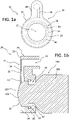
- the apparatus 10 for cleaning an object surface is formed by a main body 11 provided with an opening 12 with a circumferentially extending flexible part, flange or lip 13 partly covering an object surface 102 in circumferential direction thereof and in engagement with the object surface 102 with a pretension force.
- An object 100 will in the following example description comprise a body or housing 101, and wherein the object surface 102 will be the surface of the body or housing 101 or object 100 itself.
- the apparatus 10 for cleaning an object surface is adapted to be arranged to and accommodate a part of an object 100.
- the object 100 is camera, such as a vehicle-mounted camera.
- An object 100, such as a camera is typically formed by a housing 101 arranged for accommodating a camera with a lens 103, wherein the lens 103 is e.g. mainly circular as shown, and wherein surface of the lens 103 forms the object surface 102, e.g. with a convex shape, as shown in the example.
- the camera will typically be arranged in connection with a vehicle exterior surface.
- the object surface 102 will thus be subject to foreign matter, such as dust, rain, snow, fog, ice, mud, etc., limiting the function or visibility of the object 100, i.e. camera.
- the apparatus 10 for cleaning an object surface is formed by a main body 11 adapted to be arranged to and accommodating a part of the object 100, in the shown example the lens 103 of the camera.
- the main body 11 is formed by a housing 20 and a mainly disc-shaped body 30 integrated with the housing 20 to form one unit.
- the mainly disc-shaped body 30 is provided with an inner centrally through hole 31 adapted for being arranged to and accommodating a part of the object 100, in the shown example the lens 103 of the camera, and wherein inner wall 32 of the inner centrally through hole 31 is provided with sealing means 33, such as an O-ring, for providing a sealed barrier between the object 100, i.e.
- the sealing means 33 will in this embodiment also work as attachment means for the mainly disc-shaped body 30 to the object 100, i.e. camera.
- the apparatus 10 for cleaning an object surface is further provided with cleaning means for cleaning the object surface 102 by that the apparatus 10 is arranged for supply of cleaning fluid interior of the main body 11.
- the mainly disc-shaped body 30 is provided with at least one through hole 34, in the shown embodiment at least two through holes 34 distributed in circumferential direction thereof, for supplying cleaning fluid in circumferential direction of the object surface 102, i.e. surface of the lens 103 in the example.
- the housing 20 of the apparatus 10 is further in the shown embodiment provided with a channel 21 extending in circumferential direction of the housing 20 enclosing the at least one through hole 34 of the mainly disc-shaped body 30 and in fluid communication with the at least one through hole 34 for supplying cleaning fluid to the at least one through hole 34 in the mainly disc-shaped body 30.
- the channel 21 and at least one through hole 34 of the mainly disc-shaped body 30 are arranged close to exterior wall 22 of the housing 20.
- the opening 12 of the main body 11 is in this embodiment arranged in the exterior wall 22 of the housing 20, arranged in correspondence with the through hole 31, wherein the opening 12 has a smaller diameter than the diameter of the inner through hole 31, wherein the diameter of the opening 12 is adapted to the field of view/function area of the object 100, i.e. field of view of the lens 103 in the shown example.
- the apparatus 10 for cleaning an object surface is arranged to the object 100, i.e. the camera in the shown embodiment, the apparatus 10 for cleaning object surface is enclosing and accommodating a part (i.e. the lens 103) of the object 100, such that exterior wall 22 lies onto the object surface 102, in circumferential direction thereof.
- At least a part, flange or lip 13 of the opening 12, i.e. exterior wall 22 surrounding the object surface 102 is formed by a flexible material or a material exhibiting flexible properties, and lying onto the object surface 102 with a pretension force.
- the flexible part, flange or lip 13 of the opening 12, i.e. exterior wall 22, is formed by a flexible material or a material exhibiting flexible properties the flexible part, flange or lip 24 is adapted to be manipulated by cleaning fluid pressure in the main body 11 of the apparatus 10 such that it bends away from the object surface 102 with the free end when subjected to cleaning fluid supplied interior of the main body 11, in the shown embodiment via the at least one through hole 34 of the mainly disc-shaped body 30.
- the apparatus 10 for cleaning an object surface is further arranged to a cleaning fluid supply, which according to the shown embodiment is achieved by that the housing 20 is provided with an extension 23 at one side for connecting the channel 21 to a supply channel 24 for cleaning fluid.
- the supply channel 24 can, in the mentioned example of vehicle-mounted camera, be arranged to a supply system for cleaning of windshield, rear window or light of a vehicle, such that when cleaning fluid is supplied to the windshield, rear window or lights of a vehicle, cleaning fluid is also supplied to the apparatus 10 or by separate control.
- the apparatus 10 for cleaning object surface is arranged to a separate supply for supply of cleaning fluid.
- the apparatus 10 for cleaning an object surface works such that when cleaning fluid is supplied to the object surface 102 via the at least one through hole 34 in the mainly disc-shaped body 30, in circumferential direction of the object surface 102, the flexible part, flange or lip 13 of the opening 12/exterior wall 22 will, due to pressure of the supplied cleaning fluid, be lifted at the free end thereof from the object surface 102, resulting in that cleaning fluid will flow from circumferential direction of the object surface 102 and towards centre of the object surface 102, whereupon the cleaning fluid will be ejected away from the object surface 102 along longitudinal axis of the object 100. It should further be mentioned that opening 12/exterior wall 22 via the flexible part, flange or lip 13 will seal against the object surface 102 when cleaning is not performed.
- FIG. 2 is a principle drawing of an embodiment of the apparatus 10 for cleaning an object surface according to the present invention adapted for use with an object 100 in the form of a sensor.
- the main body 11 of the apparatus 10 according to this embodiment is formed by a mainly cylinder-shaped body 30 adapted to receive and accommodate the object 100, i.e. the sensor, at a closed or open end 36 thereof.
- the housing 20 is in this embodiment mainly cylinder-shaped and adapted for arrangement to the mainly cylinder-shaped body 30 by that the mainly cylinder-shaped housing 20 and mainly cylinder-shaped body 30 are provided with corresponding connection means in the form of threads 50, 51, respectively.
- the mainly cylinder-shaped body 30 exhibits a part with a smaller diameter and wherein the part with smaller diameter is provided with exterior threads 51, at lower end thereof.
- the mainly cylinder-shaped housing 20 is at lower part of the mainly cylinder-shaped housing 20 provided with interior threads 50, adapted for engagement with the exterior threads 51 of the mainly cylinder-shaped body 30 such that the mainly cylinder-shaped housing 20 can be fixed to the mainly cylinder-shaped body 30 via the interaction of the threads 50, 51.
- the exterior diameter of the mainly cylinder-shaped body 30 and the interior diameter of the cylinder-shaped housing 20 are adapted such that there is provided an annulus 200 between the mainly cylinder-shaped body 30 and the mainly cylinder-shaped housing 20 when they are arranged together, and wherein there is arranged sealing means 33, such as an O-ring, at lower part of the annulus 200 providing a sealed barrier at lower side of the apparatus 10/main body 11.
- the mainly cylinder-shaped body 30 is further provided with at least one through hole 34, preferably at least two through holes 34, diametrically arranged in circumferential direction thereof for supplying cleaning fluid to the annulus 200, preferably at a lower part thereof.
- the mainly cylinder-shaped body 30 is further provided with an interior cleaning fluid supply channel 37 for supplying cleaning fluid to the at least one through hole 34.
- the main body 11 is provided with an opening 12 in the housing 20 provided with a part, flange or lip 13 exhibiting a smaller diameter than the interior diameter of the mainly cylinder-shaped housing 20, as described for the prior embodiments.
- the flexible part, flange or lip 13 is also in this embodiment formed by a flexible material or material exhibiting flexible properties, and lying onto the objects surface 102, which in this embodiment is the upper end of the body 30/object surface 102 with a pretension force, as well as allowing the flexible part, flange or lip 13 to bend away from the end/object surface 102, and thus object 100 arranged therein, with the free end when subjected to cleaning fluid supplied to the annulus 200 via the at least one through hole 34.
- the channel 37 of the mainly cylinder-shaped body 30 is, e.g. for an object 100 in the form of a vehicle-mounted sensor, arranged to a supply system for cleaning of windshield, rear window or light of a vehicle, such that when cleaning fluid is supplied to the windshield, rear window or lights of a vehicle, cleaning fluid is also supplied to the apparatus 10 or by separate control.
- the apparatus 10 for cleaning object surface is arranged to a separate supply for supply of cleaning fluid.
- the apparatus 10 for cleaning an object surface works similar to the prior described embodiments by that that when cleaning fluid is supplied to the annulus 200 via the at least one through hole 34, the flexible part, flange or lip 13 will, due to pressure of the supplied cleaning fluid, be lifted at the free end thereof from the object surface 102, and accordingly the object 100, resulting in that cleaning fluid will flow from a circumferential direction and towards center of the object surface 102, whereupon the cleaning fluid will be ejected away from the object surface 102 along longitudinal axis of the object 100/mainly cylinder-shaped body 30.
- the flexible part, flange or lip 13 of the main body 11/exterior wall 22 of the housing 20 due to the pretension force will seal against the object surface 102 of the mainly cylinder-shaped body 30 or object 100 when cleaning is not performed.
- cleaning fluid in the form of liquid, (compressed) air or steam are suitable in this embodiment.
- FIG. 3 is a principle drawing of an alternative embodiment of the embodiment in Figure 2 .
- the housing 20 at inner circumference thereof or the cylinder-shaped body 30 at exterior circumference thereof is provided with deflectors 210 or nozzles inclined in relation to the horizontal plane.
- the inclination of the deflectors 210 or nozzles will provide a rotation of the supplied fluid in the annulus 200 resulting in a whirling motion of the fluid towards the flexible part, flange or lip 13 and the opening 12 thereof.
- This whirling motion would e.g. be favorable for removing snow or ice attached to the object surface 102.
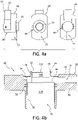
- FIGS. 4a-b show principle drawings of an alternative embodiment of the apparatus 10 for cleaning an object surface according to the present invention adapted for use with an object 100 arranged in an object housing 110.
- the mainly disc-shaped body 30 constitutes an integrated part of the housing 20.
- the flexible part, flange or lip 13 of the main body 11/exterior wall 22 of the housing 20 is arranged at end of a protruding part 25, extending mainly perpendicularly from the exterior wall 22, and positioning the flexible part, flange or lip 13 in a parallel horizontal plane of the exterior wall 22.
- Inner wall 26 of the protruding part 25 can further be provided with spacers (not shown) in circumferential direction thereof for centering the object 100/object housing 110.
- the part 25 is also formed by a flexible material or material exhibiting flexible properties.
- FIG. 5a-c showing principle drawing of a modified embodiment of the apparatus 10 for cleaning an object surface 102 shown in Figures 1a-b .
- the apparatus 10 for cleaning an object surface in addition to cleaning the object surface 102 with cleaning fluid is also arranged for physical cleaning of the object surface 102 by means of a mechanical cleaning assembly 300.
- the apparatus 10 for cleaning an object surface includes the same features as described for the embodiment described under Figure 1a-b , i.e. the housing 20 and mainly disc-shaped body 30 and associated parts.
- the housing 20 is arranged to the mainly disc-shaped body 30 by means of corresponding connection means in the form of threads 50 and 51, respectively, arranged at inner circumference of the housing 20 and outer circumference of the mainly disc-shaped body 30.
- sealing means 52 such as an O-ring, for providing a sealed barrier lower side of the apparatus 10 for cleaning object surface.
- the mainly disc-shaped body 30 is further arranged for accommodating the mechanical cleaning assembly 300.
- the mechanical cleaning assembly 300 is in this embodiment formed by a mechanical cleaning device 310 and a driving unit 320.
- the driving unit 320 is in this embodiment fluid driven, i.e. driven by cleaning fluid.
- the driving unit 320 comprises at least one rotor 321-322.
- the driving unit 320 comprises an outer rotor 321 in the form of a mainly disc-shaped turbine wheel, and an inner rotor 322 in the form of a mainly disc-shaped turbine wheel.
- the at least one through hole 34 in the mainly disc-shaped body 30 is inclined, wherein longitudinal center axis through the at least one inclined through hole 34 exhibits an angle deviating from a central axis through the mainly disc-shaped body 30.
- the outer rotor 321 is arranged to be accommodated and rotate within the mainly disc-shaped body 30, which outer rotor 321 is provided with inclined through holes 323 for providing the interior of the mechanical cleaning assembly 300 with cleaning fluid, wherein longitudinal center axis through the inclined through holes 323 exhibit an angle deviatingfrom a central axis through the mainly disc-shaped body 30, wherein the inclined through holes 323 deviate in the opposite direction of the at least one inclined through hole 34 of the mainly disc-shaped body 30.
- the inner rotor 322 is arranged to be accommodated and rotate within the outer rotor 321, which inner rotor 322 is provided with inclined through holes 324 for providing the interior of the mechanical cleaning assembly 300 with cleaning fluid, wherein longitudinal center axis through the inclined through holes 324 exhibit an angle deviating from a central axis through the mainly disc-shaped body 30, wherein the inclined through holes 324 deviate in the opposite direction of the through holes 323 of the outer rotor 321.
- the outer 321 and inner 322 rotor are arranged to rotate in an annular recess 35 in the mainly disc-shaped body 30 due to supply of cleaning fluid and the inclined holes 34, 323 and 324.
- the mechanical cleaning assembly 300 is further provided with a locking mechanism.
- a locking mechanism In the shown embodiment, this is achieved by that the inner rotor 322 is provided with an elastic lock element 330 with an extension along a part of the outer circumference of the inner rotor 322.
- the elastic lock element 330 is fixed to the inner rotor 322 at one end and free at the other end, allowing it to be manipulated by cleaning fluid pressure in the mechanical cleaning assembly 300.
- the elastic lock element 330 is at the free end provided with a protruding locking element 331 adapted to be received in a locking recess 332 arranged in the inner circumference of the outer rotor 321.
- the locking recess 332 is preferably tapered from one end to ensure that the protruding element 331 safely comes into engagement with the locking recess 332. Accordingly, the elastic lock element 330 is designed such that it exhibits a pretention force, which initially ensure that the protruding locking element 331 is in engagement with the locking recess 332.
- the mechanical cleaning device 310 is preferably in the form of an elastic element, such as thread, wire, wiper, chain or similar, arranged/fixed to the outer rotor 321 at one end and arranged/fixed to the inner rotor 322 at the other end.
- an elastic element such as thread, wire, wiper, chain or similar
- the apparatus 10 for cleaning an object surface with the mechanical cleaning assembly 300 works in the way that when cleaning fluid is supplied via the supply channel 21, the cleaning fluid will flow into the at least one inclined through hole 34 of the mainly disc-shaped body 30, and further into the inclined through holes 323 of the outer rotor 321 and into the through holes 324 of the inner rotor 322 and flow from the circumference of the object surface 102 and towards center of the object surface 102.
- the pressure of the cleaning fluid in the mechanical cleaning assembly 300 has reached a certain pressure, the protruding locking element 331 of the elastic lock element 330 will be forced out of engagement with the locking recess 332 of outer rotor 321 resulting in that the inner 322 and outer 321 rotor will start to rotate.
- the rotation of the outer rotor 321 and inner rotor 322 will result in that the mechanical cleaning device 310 will start to move in a more or less random or fixed pattern by that the fixed ends of the mechanical cleaning device 310 in the outer rotor 321 and inner rotor 322 rotate, at the same time as the mechanical cleaning device 310 will be affected by the flow of cleaning fluid over the object surface 102.
- the outer 321 and inner 322 rotor will rotate in the opposite directions or in the same direction. When rotated in the same direction it will be preferable that they are rotated with different rotational velocity.
- the rotational velocity will depend on the size of the respective inclined through holes, as well as the number of inclined through holes in the respective rotor, as well as the mainly disc-shaped body 30.
- the locking mechanism 330 of the mechanical cleaning device 310 will be cleaning fluid activated, ensuring that the mechanical cleaning device 310 will not move in relation to the object surface 102 before the object surface 102 is wetted which is achieved by that a certain pressured is required to allow rotation of the rotors 321-322.
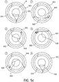
- Figure 5c show principle drawings of a time series of how the mechanical cleaning device 310 will exhibit a different pattern depending how the fixation/arrangement points of the mechanical cleaning device 310 in the outer rotor 321 and inner rotor 322 are positioned in relation to each other. Accordingly, depending on the position of the fixation/arrangement points of the mechanical cleaning device 310 in the inner rotor 322 and outer rotor 321, the mechanical cleaning device 310 will be tightened and loosened in a random or fixed pattern ensuring that the object surface 102 will be cleaned from any film or material deposited thereon, as well as water droplets.
- the inner rotor 322 When the cleaning fluid supply is cut, the inner rotor 322 will stop to rotate when the pressure of the cleaning fluid drops to a certain pressure, whereupon the pretension force in the elastic lock element 330 will result in that the outer rotor 321 is stopped by that the locking element 331 comes into engagement with the locking recess 332 and at the same time the mechanical cleaning device 310 will be in a position outside the field of view/function area object 100.
- FIG. 6a-b is a principle drawing of an alternative embodiment of the apparatus 10 for cleaning object surface with mechanical cleaning assembly 300 in Figures 5a-c .
- the apparatus 10 for cleaning an object surface according to this embodiment includes the same features as described for the embodiment in Figures 1a-b and 5a-c as regards the housing 20 and the mainly disc-shaped body 30.
- the mechanical cleaning assembly 300 in this embodiment comprises a driving unit 320 comprising only one rotor 321.
- the mainly disc-shaped body 30 is provided with at least one inclined through hole 34 and the rotor 321 is arranged to be accommodated and rotating in the mainly disc-shaped body 30, and wherein the at least one inclined through hole 323 of the rotor 321 deviate in the opposite direction of the at least one inclined through hole 34 of the mainly disc-shaped body 30.
- the rotor 321 comprises as above an elastic lock element 330 with an extension along a part of the outer circumference of the rotor 321, but the locking recess 332 is in this embodiment arranged at the inner circumference of the mainly disc-shaped body 30.
- the mechanical cleaning device 310 is fixed inside the housing 20 or to the body 30 at one side, i.e. unlike the embodiment in Figures 5a-c , and will not rotate, but will be stationary at all time.
- the other end arranged to the rotor 321 will move and provide a more or less random or fixed pattern for movement of the mechanical cleaning device 310 over the object surface 102, as shown in Figure 6b .
- the mechanical cleaning assembly 300 will work similarly as the embodiment described in Figures 5a-c , by that the cleaning fluid will flow through the at least one inclined through hole 34 of the mainly disc-shaped body 30 and inclined through holes 323 of rotor 321 and when a certain cleaning fluid pressure is achieved the protruding element 331 of the elastic lock element 330 is released from engagement with the locking recess 332. As the rotor 321 rotates this will result in that one end of the mechanical cleaning device 310 is provided with a circumferential movement which will result in a more or less random or fixed pattern of the mechanical cleaning device 310 over the object surface 102.
- FIGS 7a-b are principle drawings of a further embodiment of the apparatus 10 according to the present invention.
- the main body 11 is formed by a mainly disc-shaped housing 20 and a mainly disc-shaped body 30, as described for the previous embodiments.
- the flexible part, flange or lip 13 is in this embodiment formed as a separate component, wherein the housing 20 at upper part is adapted to receive and accommodate the flexible part, flange or lip 13 and held in place by a fixation plate 29, which is detachably arranged to the housing 20 by means of corresponding threads.
- the housing 20 is as in the previous embodiments arranged for receiving and accommodating the mechanical cleaning assembly 300.
- the mechanical cleaning assembly 300 can be formed as in any one of the described embodiments. In the shown embodiment is however an alternative embodiment of the mechanical cleaning assembly 300 of the one in Figures 6a-b shown.
- the mainly disc-shaped body 30 is provided with at least one inclined through hole 34 and the rotor 321 is arranged to be accommodated and rotating in the mainly disc-shaped body 30.
- This embodiment is based on the use of a rotor 321 provided with propeller blades 325 at exterior surface thereof, deviating with an angle in the opposite direction of the at least one inclined through hole 34 of the mainly disc-shaped body 30.
- the rotor 321 and mainly disc-shaped main body 30 are provided with interior corresponding locking devices 330.
- By supplying cleaning fluid via the at least one through hole 34 this will result in that the propeller blades 325 rotates the rotor 321 as well as lifting the rotor 321 from the mainly disc-shaped main body 30 upwards limited by the flexible part, flange or lip 13 such that the locking devices 330 goes out of engagement with each other and the rotor 321 is free to rotate, similar to the embodiment of Figures 6a-b
- the mechanical cleaning device 310 will similarly to the embodiment of Fig. 6a-b also in this embodiment be fixed at one end to the main body 30 or the housing 20, and at the other end be arranged to the rotor 321 as described above.
- the function and operation of the mechanical cleaning assembly 300 is similar to the one described in Figures 6a-b .
- the driving unit 320 is formed by a rotor 321 and a stator 340, wherein the stator the stator 340 is arranged fixed in the annular recess 35 of the mainly disc-shaped body 30 and the rotor 321 is arranged to rotate within the stator 340.
- the stator 340 can alternatively be an integrated part of the mainly disc-shaped body 30 or housing 20.
- the stator 340 is connected to a power supply source 350 and the rotor 321 will be provided with permanent magnets or windings distributed along the circumference thereof.
- the mechanical cleaning device 310 will be arranged/fixed at one end to the rotor 321, while at the other end is arranged/fixed to the mainly disc-shaped body 30 or housing 20. This embodiment enables cleaning by the mechanical cleaning device 310 both with cleaning fluid and without cleaning fluid.
- the mechanical cleaning device 310 can thus also be used as a wiper without cleaning fluid.
- an electrically driven solution one can use a delay to be sure that the object surface is wetted before the mechanical cleaning device 310 is operated.
- An electrically driven solution can also be used to ensure that the mechanical cleaning device 310 is positioned out of the field of view/function area of the object 100 when cleaning is not performed by that one know the position of the rotor 321, and thus the fixation point of the mechanical cleaning device 310.
- By appropriate controlling one can thus position the rotor 321 and thus fixation/arrangement point of the mechanical cleaning device 310 thereon in a position where one is sure that the mechanical cleaning device 310 is positioned out of the field of view/function area of the object 100.
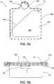
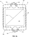
- Figures 9a-b are principle drawing of an alternative embodiment of the mechanical cleaning assembly 300 according to the present invention.
- the object 100 is exemplified by a light of a vehicle or camera.
- the mechanical cleaning assembly 300 is mechanically driven.
- the driving unit 320 for the mechanical cleaning device 310 comprises a chain 360, wire, belt or thread arranged for moving in a track 361 extending mainly along the circumference of the object surface 102, i.e. the chain 360 is arranged to rotate along the circumference of the object surface 102.
- the driving unit 320 further comprises a cogwheel 370 providing movement of the chain 360, wire, belt or thread, wherein the rotational movement of the cogwheel 370 is provided by an electric motor (not shown).
- the mechanical cleaning device 310 will in this embodiment be arranged/fixed at one end to a position on the chain 360, wire, belt or thread and at the other end is fixed/arranged to the body 11.
- a beaded chain 360 arranged to move in a mainly tubular track 361, wherein the tubular track 361 exhibits a slot (not shown) facing the interior side thereof, through which slot the mechanical cleaning device 310 extends such that the mechanical cleaning device 310 is free to move over the object surface 102.
- this embodiment enables cleaning by the mechanical cleaning device 310 both with cleaning fluid and without cleaning fluid.
- the mechanical cleaning device 310 can thus also be used as a wiper without cleaning fluid.
- this embodiment provides a solution where the chain 360, wire, belt or thread can be moved in both directions by the rotational direction of the cogwheel 370, and thus also move the mechanical cleaning device 310 in opposite directions.
- wheels, cogwheels or similar can be arranged in corners of the circumference of the object surface 102 to facilitate the movement of the chain 360, wire, belt or thread along the circumference thereof.
- Figure 9c is an alternative embodiment of the embodiment in Figures 9a-b , where both ends of the mechanical cleaning device 310 is arranged to separate chains 360, wires, belts or threads or threads, moving in the same direction or opposite direction. When moved in the same direction it will be preferable that the cogwheels 370 are operated at different rotational velocity. This embodiment will work similarly to the one described in Figures 5a-c .
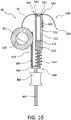
- FIG. 10 is a principle drawing of a further embodiment of the apparatus 10 according to the present invention. Parts of the main body 11 are omitted in the shown embodiment for revealing details.
- the driving unit 320 for the mechanical cleaning device 310 is mechanically driven.
- the driving unit 320 comprises a pitch rack 380 arranged in rotational engagement with the rotor 321 by means of a transmission device (not shown), such as one or more cogwheels, transferring longitudinal movement of the pitch rack 380 to rotational movement of the rotor 321.
- the driving unit 320 is in this embodiment arranged to a driving device 400 providing longitudinal movement of the pitch rack 380.
- an assembly 500 for supplying cleaning fluid to the apparatus shown which can be operated at the same time as the mechanical cleaning device 310 is operated.
- the driving device 400 is formed by a shaft 401 driven by a driving source 402, such as an electric motor or a solenoid, for moving the shaft 401 in a longitudinal direction of the driving source 402.
- a driving source 402 such as an electric motor or a solenoid
- the shaft 401 is extending through the solenoid 402 and wherein the shaft 401 at one end 403 is connected to the driving unit 320 of the mechanical cleaning assembly 300 and the assembly 500 for supplying cleaning fluid.
- the assembly 500 for supplying cleaning fluid is in the shown embodiment comprising a piston assembly 510 comprising a cylinder 511, wherein a piston 512 operated by a piston rod 513 is arranged.
- the cylinder 511 is at one side of upper part thereof provided with a fluid inlet 520 connected to a fluid supply 530 via a non-return valve 521.
- the cylinder 511 is further at the opposite side at the upper part thereof provided with a fluid outlet 540 connected to the fluid supply channel 26 of the housing 20 via a non-return valve 541.
- the mentioned pitch rack 380 and piston rod 513 of the piston assembly 500 are both arranged to the end 403 of the shaft 402 for parallel longitudinal movement.
- a spring 514 is preferably further arranged to the piston rod 513, between the cylinder 511 and the end 403 of the shaft 402.
- the chamber of the cylinder 511 will be filled with cleaning fluid when the piston 512 is in a retracted position.
- a cleaning process is activated the longitudinal movement of the shaft 402 will push cleaning fluid out of the fluid outlet 540 supplying cleaning fluid to the apparatus 10 at the same time as the pitch rack 380 is moved in longitudinal direction resulting in rotation of the rotor 321 driving the mechanical cleaning assembly 310 as described above.
- the spring 514 will ensure that the piston 512 is retracted and the shaft 402 moved longitudinally in the opposite direction.
- This opposite movement of the shaft 402 results in that the chamber of the cylinder 511 is again filled with cleaning fluid from the cleaning fluid supply 530, and that the pitch rack 380 is moved in opposite direction, resulting in that the rotor 321 is rotated in the opposite direction moving the mechanical cleaning device 310 in the opposite direction wiping of the object surface 102 like a wiper.
- the supply of cleaning fluid and operation of the mechanical cleaning device 310 is achieved in a combined manner by longitudinal movement of the shaft 402.
- the shown embodiment also gives an example of how a heating element 600 can be implemented for heating of the cleaning fluid in winter time. In the shown example, this is achieved by that the heating element 600 is attached to the cylinder 511 for heating of cleaning fluid therein. Another alternative will be that the heating element is enclosing the channel 26.
- At least one rotor 321-322 can be arranged to be rotated directly by an electrical motor or via one or more transmission devices.
- an apparatus 10 for cleaning object surface with a mechanical cleaning assembly 300 which effectively and rapidly can perform cleaning of the object surface 102 within a few seconds, as well as removing film, material or water droplets on the object surface 102 effectively.
- the mechanical cleaning device 310 at all times would be in cleaning fluid, and due to the fact that the apparatus 10 for cleaning object surface according to the present invention is arranged to ensure that cleaning fluid is present at the object surface 102 it is provided low friction and long operating time.
- the present invention is achieved a robust apparatus 10 for cleaning an object surface which will withstand the forces of a high-pressure washer due to the use of the flexible part, flange or lip 13, and the design of the mechanical cleaning assembly 300 ensures that the mechanical cleaning device 310 will be positioned behind the flexible part, flange or lip 13, protecting it at all time when not used.
- the apparatus 10 for cleaning an object surface according to the present invention further provides a compact and robust solution.
- an apparatus 10 for cleaning object surface which is easy to arrange to and dismount from the relevant object 100 it is to be used on.
- the size and shape of the mechanical cleaning device 310 can be adapted to the object surface 102 it is to be used on. It can e.g. be formed as a thread, as a wiper or similar shapes, which will be within the knowledge of a skilled person.
- Examples of objects 100 are typically vehicle-mounted sensors providing information about the surroundings, such as, but not limited to, proximity sensors, sensors for parking assistance, blind zone object detection, traffic lane departure, traffic signal identification, rear view mirror substitution etc., and lidars or other kind of sensor where it is required to clean the surface for dust, ice, snow, rain or dirt of any kind which could reduce the operation of the sensor.
- sensors on seagoing crafts, airplanes, drones or similar.
- the present invention will also be applicable for cleaning of windows, cover, signs, boards, signposts or similar, of any kind and shape.
- the principle of the present invention will be applicable on any kind of object surface, i.e. the object surface can be concave, convex or planar or any other shape. Further, the principles of the present invention will be applicable on any kind of shape of the object, such as, but not limited to, mainly rectangular, mainly quadratic, mainly disc-shaped, mainly cylindrical, or mainly cylinder-shaped.
- the apparatus 10 for cleaning an object surface can be used on cover windows/glass or housings located facing the object.
- the apparatus 10 for cleaning an object surface according to the present invention can further be arranged to use more than one cleaning fluid, hereunder also (compressed) air.
- the apparatus 10 for cleaning an object surface according to the present invention can further be arranged to an automatic activation system, which will initiate a cleaning procedure if the visibility of the object is reduced.
Description
- The present invention is related to an apparatus for cleaning an object surface, according to the preamble of
claim 1, which is disclosed by documentWO 2016/004936 . - There has lately been an increased use of optic sensors to assists drivers of motor vehicles by arrangement of sensors, such as sensors for parking assistance, blind zone object detection, traffic lane departure, traffic signal identification, rear view mirror substitution etc., and cameras, such as reversing camera and similar.
- Lately, there has also been an increasing focus on partly or entirely self-driving vehicles which, among others, is based on the use of the above-mentioned sensors. In such cases, it is extremely important that the sensors work as they are intended to.
- The optic sensors are usually arranged to or on an exterior surface of the vehicle, such that they exhibit an optic surface, such as a lens surface or cover window/glass is disposed afore the lens surface, which will be exposed to foreign matter, such as insects, rain/raindrops, fog, mud, dust, snow or ice. There is accordingly a need to remove foreign matter adhered onto the surface of vehicle-mounted cameras or sensors.
- Prior art reveals that there have been many attempts of providing cleaning devices for cleaning an optic surface of an optic sensor. Common for the most of these solutions is that they make use of a nozzle discharging washer fluid onto the optic surface from a distance from the surface of the sensor or camera.
-
US2016103316 A1 describes a cleaning device for cleaning a lens of a motor vehicle camera comprising a cleaning head arranged in a fixed position with respect to the camera. The cleaning head comprises an internal annular wall being arranged along the optical axis behind the lens and bearing cleaning means oriented towards the lens. The internal annular wall of the head is equipped with a plurality of nozzles via which a cleaning liquid is able to exit bound for the lens. - From
US2016101735 A1 is known a cleaning device for cleaning a lens of a camera, using a cleaning head, wherein the cleaning device comprises drive means for driving the camera or the cleaning head, which are able to generate a relative displacement of the cleaning head with respect to the camera between a passive position in which the cleaning head is positioned outside of the image-capturing field of the camera, and an active position in which the cleaning head extends facing the lens so as to allow cleaning liquid to be ejected towards the said lens. - In
US2015344001 A1 it is described a cleaning device for cleaning a vehicle-mounted optic surface, including a housing, the housing including an opening adapted to fit an optic surface, a fluid inlet arranged to take in washer fluid, and at least one fluid discharge port arranged to discharge washer fluid onto the optic surface, a first passage in fluidic communication with the fluid inlet and the at least one fluid discharge port so as to guide the washer fluid from the fluid inlet towards the at least one fluid discharge port and a protruding part that substantially surrounds the opening so as to define an inner wall. -
US9126534 B2 - From
US2013146577 A1 it is known a sensor or camera assembly for a vehicle comprises a housing that is mountable to a vehicle component. The sensor or camera is located within the housing and has an exterior facing surface. A defrost element is located proximate to the sensor or camera and is electrically connectable to a defrost system. The defrost element is arranged to defrost the surface of the sensor or camera. A nozzle is located proximate to the sensor or camera and is fluidly connectable to a washer system for the vehicle. The nozzle is arranged to direct a fluid from the washer system over the surface of the sensor or camera. - In
US9180840 B2 - From
US9278670 B2 - In
US9538054 B2 -
US2017036650 describes a low profile, integrated camera wash nozzle assembly readily and unobtrusively integrated into a vehicle's exterior trim surfaces. It is further described a system and nozzle assembly for cleaning an exterior objective lens or wide-angle sensor's exterior surface to remove accumulated debris sprays washer fluid at a selected shallow angle which is substantially transverse to the lenses central viewing axis. A low-profile conformal housing fixture is adapted to receive and aim a very compact fluidic circuit insert that can generate a wide spray which substantially covers the lens surface, despite being very close to the edge of the lens. - Example of other cameras that will have a need for cleaning e.g. surveillance cameras arranged in public spaces or tunnels, cameras arranged on vessels, crafts and the like. Presently there exists no suitable solutions for cleaning of the surface of such cameras.
- Other examples of objects which would require cleaning is lights of a vessel or craft, such as headlights of a vehicle, which today only can be cleaned by spraying fluid directly on the object surface, possibly assisted by wipers.
- Drawbacks of the prior art solutions are mainly that they spray cleaning fluid onto the surface from a distance and/or in an angle of the surface of the vehicle-mounted camera or sensor.
- A further drawback of most of the solutions is that require a large amount of cleaning fluid for cleaning the surface of the camera or sensor.
- Another drawback with many of the prior art solutions is that they utilize solutions which require movable parts to position the spray nozzle at a distance from the surface of the vehicle-mounted camera or sensor.
- A drawback with many of the prior art solutions is further that that one with spraying of cleaning liquid alone is not able to clean the surface completely, but will leave a film which will result in that dust and fine particles will attach to the surface over time.
- Another drawback with the prior art solutions, especially the ones with sprays cleaning liquid from a considerable distance is that the cleaning fluid will, when this is sprayed onto the lens, reduce the view of the camera or sensor during this operation.
- Another disadvantage is that the prior art solutions suffer from that the used cleaning fluid will flow down on the vehicle exterior surface, something which will attract dust, mud and similar, which potentially could damage the paint of the vehicle, as well as resulting in a visual unattractive impression of the vehicle.
- A further disadvantage with the prior art solutions is that they will only be suitable for the use on vehicle-mounted cameras and do not offer a solution that can be used for cleaning of other object surfaces.
- The main object of the present invention is to provide an apparatus for cleaning object surface partly or entirely solving the above mentioned drawbacks of prior art.
- An object of the present invention is to provide an apparatus for cleaning an object surface for improving function or visibility thereof.
- It is an object of the present invention to provide an apparatus for cleaning an object surface where cleaning fluid is supplied in contact with the object surface and remains in contact with the object surface until it is ejected away from the object surface.
- An object of the present invention is provide an apparatus for cleaning an object surface which use a flexible part, flange or lip partly covering the object surface in circumferential direction thereof and in engagement with the object surface with a pretension force ensuring that the cleaning fluid flows from a circumferential direction of the object surface and towards center of the object surface where it is ejected from the object surface.
- A further object of the present invention is to provide an apparatus for cleaning an object surface provided with a mechanical cleaning device providing both cleaning with cleaning fluid and physical cleaning of the object surface.
- It is an object of the present invention to provide an apparatus for cleaning an object surface provided with a mechanical cleaning assembly, which is moved with a more or less random pattern, or fixed pattern over the object surface.
- An object of the present invention is to provide an apparatus for cleaning an object surface that can easily be arranged to and dismounted from an object.
- It is an object of the present invention to provide an apparatus for cleaning an object surface that is applicable in a wide range of applications.
- Further objects will appear from the following description, claims and attached drawings.
- An apparatus for cleaning object surface according to the present invention is disclosed in
claim 1. - Preferable features of the apparatus for cleaning an object surface are disclosed in the dependent claims.
- The present invention is related to an apparatus for cleaning an object surface for improving function or visibility thereof.
- The object to be cleaned can according to the present invention be any object requiring cleaning of the surface thereof. The object can e.g. be, but not limited to, sensor, camera, light, window, cover, signs, boards, signposts or similar.
- The term sensor comprises any kind of sensor or camera that would have a need for cleaning of the surface thereof.
- The term light comprises any kind of light, such as, but not limited to, lights of crafts or vehicles, such as headlights, brake light, reverse lamp, other lights associated with crafts or vehicles, that would have a need for cleaning of the surface thereof.
- The term object surface also comprises surface of a cover glass/window located facing the object or a surface of a housing located facing the object.
- The apparatus for cleaning an object surface comprises a main body adapted to be arranged to or to accommodate a part of the object. The main body will typically be mainly disc-shaped or cylinder-shaped, but can also exhibit other shapes.
- According to the present invention, the main body of the apparatus for cleaning an object surface is provided with an opening with a circumferentially extending flexible part, flange or lip partly covering the object surface in circumferential direction thereof and in engagement with the object surface with a pretension force. The opening in the main body is adapted such that it do not limit the field of view/function of the object.
- According to the present invention, the apparatus for cleaning an object surface is further arranged to supply cleaning fluid interior of the main body.
- According to a further embodiment of the present invention, the apparatus is arranged to supply cleaning fluid in a circumferential direction of the object surface.
- According to the present invention, cleaning fluid is supplied in contact with the object surface and remains in contact with the object surface until it is ejected away from the object surface.
- Further, the flexible part, flange or lip extending in circumferential direction of the opening of the main body is arranged to bend away from the object surface when subjected to cleaning fluid supplied interior of the main body.
- By the present invention is achieved that cleaning fluid flows from a circumferential direction of the object surface and towards center of the object surface where it is ejected mainly perpendicularly away from the object surface.
- Supply of cleaning fluid in circumferential direction is according to one embodiment of the present invention achieved by that the main body is provided with at least one through hole for supplying cleaning fluid in circumferential direction of the object surface.
- The main body exhibits a shape and size adapted the relevant object the apparatus for cleaning an object surface is to be used on.
- According to an alternative embodiment, the main body is arranged to accommodate and enclose the object therein.
- According to the present invention, the apparatus for cleaning an object surface can further comprise sealing means between the main body and the object, which in addition to providing a sealing barrier for cleaning fluid in the apparatus for cleaning object surface also can work as attachment means for the main body to the object.
- According to a further embodiment of the present invention, the main body of the apparatus for cleaning an object surface is provided with an interior or exterior channel for supplying cleaning fluid to the at least one through hole in the main body.
- According to a further embodiment of the apparatus for cleaning an object surface according to the present invention the apparatus for cleaning object surface further comprises a mechanical cleaning assembly comprising a mechanical cleaning device for physical cleaning of the object surface.
- In one embodiment according to the present invention, the mechanical cleaning device is formed by an elastic element, such as a thread, wire, wiper, chain or similar.
- According to a further embodiment of the present invention, the mechanical cleaning device is arranged at one end to the main body and a driving unit at the other end, or arranged to a driving unit at both ends.
- According to the present invention, the mentioned driving unit(s) is/are driven by cleaning fluid or mechanically or electrically.
- By this is achieved a mechanical cleaning device which will move over and in contact with the object surface with a more or less random or fixed pattern, and further ensure that parts of or the entire object surface is cleaned in only a few cycles.
- According to a further embodiment of the apparatus according to the present invention it, to ensure that the object surface is wetted by cleaning fluid when the mechanical cleaning device is used, the mechanical cleaning assembly further comprises a locking mechanism for the mechanical cleaning device. The locking mechanism will also ensure that the mechanical cleaning device is protected and positioned out of the field of view/function area for the object when cleaning is not performed.
- Accordingly, by the present invention is provided an apparatus for cleaning an object surface with or without a mechanical cleaning assembly, which will have considerable advantages over prior art solutions.
- The apparatus for cleaning an object surface according to the present invention is compact and robust and contains no exterior movable parts.
- The apparatus for cleaning an object surface according to the present invention provides a solution being more effective than the prior art solutions due to that the cleaning fluid will be supplied in contact with the object surface and remains in contact with the object surface until it is ejected away from the object surface. This also results in that the amount of cleaning fluid required can be reduced.
- Further, the use of a flexible part, flange or lip enclosing the object surface provides a solution, which is sealed at all time when not in use.
- By the present invention is achieved an apparatus for cleaning an object surface which in an easy manner can be arranged to and dismounted from an object.
- By the present invention is further achieved an apparatus for cleaning an object surface which can be adapted to any kind of existing or new object. Accordingly, the principle described in the present invention can be adapted objects having different shapes, such as, but not limited to, mainly cylindrical, mainly quadratic, mainly rectangular, as well as objects having different surface shape, such as, but not limited to, convex, concave or planar.
- The apparatus for cleaning an object surface according to the present invention solves the problem of cleaning fluid flowing down on exterior surface of a structure where the object is arranged, by that the cleaning fluid is ejected away from the object surface.
- The apparatus for cleaning an object surface according to the present invention is suitable for using any fluid, such as, but not limited to, steam, water, windscreen washer liquid and air or a combination of these.
- By the apparatus for cleaning an object surface according to the present invention is further achieved a solution, which also is capable of removing film or material deposited on the object surface, as well as water droplets.
- The present invention accordingly provides an apparatus that can be used for cleaning the surface of any kind of object.
- Further preferable features and advantageous details of the present invention will appear from the following example description, claims and attached drawings.
- The present invention will below be described in further detail with references to the attached drawings, where:
-
Figures 1a-b are principle drawings of a first embodiment of an apparatus for cleaning an object surface according to the present invention arranged to an object, -
Figure 2 is a principle drawing of second embodiment of an apparatus for cleaning an object surface according to the present invention, -
Figure 3 is a principle drawing of an alternative embodiment of the apparatus inFigure 2 , -
Figures 4a-b are principle drawings of a further embodiment of the apparatus for cleaning an object surface according to the present invention, -
Figures 5a-c are principle drawings an embodiment of the apparatus for cleaning an object surface according to the present invention provided with a mechanical cleaning assembly, -
Figures 6a-b are principle drawings of an alternative embodiment of the apparatus for cleaning an object surface according to the present invention provided with a mechanical cleaning assembly, -
Figures 7a-b are principle drawings of a further alternative embodiment of the apparatus for cleaning an object surface according to the present invention, -
Figures 8a-b are principle drawings of a further alternative embodiment of the apparatus for cleaning an object surface according to the present invention, -
Figures 9a-c are principle drawings of a further embodiment of the apparatus for cleaning an objects surface according to the present invention provided with a mechanical cleaning assembly, and -
Figure 10 is a principle drawing of a further embodiment of the apparatus for cleaning an objects surface according to the present invention. - The
apparatus 10 for cleaning an object surface according to the present invention is formed by amain body 11 provided with anopening 12 with a circumferentially extending flexible part, flange orlip 13 partly covering anobject surface 102 in circumferential direction thereof and in engagement with theobject surface 102 with a pretension force. Anobject 100 will in the following example description comprise a body orhousing 101, and wherein theobject surface 102 will be the surface of the body orhousing 101 or object 100 itself. - Reference is now made to
Figures 1a-b which are principle drawings of a first embodiment of anapparatus 10 for cleaning an object surface according to the present invention. According to the first example embodiment, theapparatus 10 for cleaning an object surface is adapted to be arranged to and accommodate a part of anobject 100. In the shown example, theobject 100 is camera, such as a vehicle-mounted camera. Anobject 100, such as a camera, is typically formed by ahousing 101 arranged for accommodating a camera with alens 103, wherein thelens 103 is e.g. mainly circular as shown, and wherein surface of thelens 103 forms theobject surface 102, e.g. with a convex shape, as shown in the example. In connection with the example, which is a vehicle-mounted camera, the camera will typically be arranged in connection with a vehicle exterior surface. Theobject surface 102 will thus be subject to foreign matter, such as dust, rain, snow, fog, ice, mud, etc., limiting the function or visibility of theobject 100, i.e. camera. - According to the first embodiment of the present invention, the
apparatus 10 for cleaning an object surface is formed by amain body 11 adapted to be arranged to and accommodating a part of theobject 100, in the shown example thelens 103 of the camera. In the shown embodiment, themain body 11 is formed by ahousing 20 and a mainly disc-shapedbody 30 integrated with thehousing 20 to form one unit. In the shown example, the mainly disc-shapedbody 30 is provided with an inner centrally throughhole 31 adapted for being arranged to and accommodating a part of theobject 100, in the shown example thelens 103 of the camera, and whereininner wall 32 of the inner centrally throughhole 31 is provided with sealing means 33, such as an O-ring, for providing a sealed barrier between theobject 100, i.e.lens 103, and the mainly disc-shapedbody 30, in circumferential direction of theobject 100, i.e.lens 103. The sealing means 33 will in this embodiment also work as attachment means for the mainly disc-shapedbody 30 to theobject 100, i.e. camera. - The
apparatus 10 for cleaning an object surface is further provided with cleaning means for cleaning theobject surface 102 by that theapparatus 10 is arranged for supply of cleaning fluid interior of themain body 11. In the shown embodiment this is achieved by that the mainly disc-shapedbody 30 is provided with at least one throughhole 34, in the shown embodiment at least two throughholes 34 distributed in circumferential direction thereof, for supplying cleaning fluid in circumferential direction of theobject surface 102, i.e. surface of thelens 103 in the example. Thehousing 20 of theapparatus 10 is further in the shown embodiment provided with achannel 21 extending in circumferential direction of thehousing 20 enclosing the at least one throughhole 34 of the mainly disc-shapedbody 30 and in fluid communication with the at least one throughhole 34 for supplying cleaning fluid to the at least one throughhole 34 in the mainly disc-shapedbody 30. Thechannel 21 and at least one throughhole 34 of the mainly disc-shapedbody 30 are arranged close toexterior wall 22 of thehousing 20. - The
opening 12 of themain body 11 is in this embodiment arranged in theexterior wall 22 of thehousing 20, arranged in correspondence with the throughhole 31, wherein theopening 12 has a smaller diameter than the diameter of the inner throughhole 31, wherein the diameter of theopening 12 is adapted to the field of view/function area of theobject 100, i.e. field of view of thelens 103 in the shown example. - Accordingly, when the
apparatus 10 for cleaning an object surface is arranged to theobject 100, i.e. the camera in the shown embodiment, theapparatus 10 for cleaning object surface is enclosing and accommodating a part (i.e. the lens 103) of theobject 100, such thatexterior wall 22 lies onto theobject surface 102, in circumferential direction thereof. - At least a part, flange or
lip 13 of theopening 12, i.e.exterior wall 22 surrounding theobject surface 102 is formed by a flexible material or a material exhibiting flexible properties, and lying onto theobject surface 102 with a pretension force. By that the flexible part, flange orlip 13 of theopening 12, i.e.exterior wall 22, is formed by a flexible material or a material exhibiting flexible properties the flexible part, flange orlip 24 is adapted to be manipulated by cleaning fluid pressure in themain body 11 of theapparatus 10 such that it bends away from theobject surface 102 with the free end when subjected to cleaning fluid supplied interior of themain body 11, in the shown embodiment via the at least one throughhole 34 of the mainly disc-shapedbody 30. - The
apparatus 10 for cleaning an object surface is further arranged to a cleaning fluid supply, which according to the shown embodiment is achieved by that thehousing 20 is provided with anextension 23 at one side for connecting thechannel 21 to asupply channel 24 for cleaning fluid. E.g. thesupply channel 24 can, in the mentioned example of vehicle-mounted camera, be arranged to a supply system for cleaning of windshield, rear window or light of a vehicle, such that when cleaning fluid is supplied to the windshield, rear window or lights of a vehicle, cleaning fluid is also supplied to theapparatus 10 or by separate control. Alternatively, theapparatus 10 for cleaning object surface is arranged to a separate supply for supply of cleaning fluid. - Accordingly, the
apparatus 10 for cleaning an object surface according to the above described embodiment works such that when cleaning fluid is supplied to theobject surface 102 via the at least one throughhole 34 in the mainly disc-shapedbody 30, in circumferential direction of theobject surface 102, the flexible part, flange orlip 13 of theopening 12/exterior wall 22 will, due to pressure of the supplied cleaning fluid, be lifted at the free end thereof from theobject surface 102, resulting in that cleaning fluid will flow from circumferential direction of theobject surface 102 and towards centre of theobject surface 102, whereupon the cleaning fluid will be ejected away from theobject surface 102 along longitudinal axis of theobject 100. It should further be mentioned that opening 12/exterior wall 22 via the flexible part, flange orlip 13 will seal against theobject surface 102 when cleaning is not performed. - Reference is now made to
Figure 2 which is a principle drawing of an embodiment of theapparatus 10 for cleaning an object surface according to the present invention adapted for use with anobject 100 in the form of a sensor. Themain body 11 of theapparatus 10 according to this embodiment is formed by a mainly cylinder-shapedbody 30 adapted to receive and accommodate theobject 100, i.e. the sensor, at a closed oropen end 36 thereof. Thehousing 20 is in this embodiment mainly cylinder-shaped and adapted for arrangement to the mainly cylinder-shapedbody 30 by that the mainly cylinder-shapedhousing 20 and mainly cylinder-shapedbody 30 are provided with corresponding connection means in the form ofthreads body 30 exhibits a part with a smaller diameter and wherein the part with smaller diameter is provided withexterior threads 51, at lower end thereof. The mainly cylinder-shapedhousing 20 is at lower part of the mainly cylinder-shapedhousing 20 provided withinterior threads 50, adapted for engagement with theexterior threads 51 of the mainly cylinder-shapedbody 30 such that the mainly cylinder-shapedhousing 20 can be fixed to the mainly cylinder-shapedbody 30 via the interaction of thethreads - The exterior diameter of the mainly cylinder-shaped
body 30 and the interior diameter of the cylinder-shapedhousing 20 are adapted such that there is provided anannulus 200 between the mainly cylinder-shapedbody 30 and the mainly cylinder-shapedhousing 20 when they are arranged together, and wherein there is arranged sealing means 33, such as an O-ring, at lower part of theannulus 200 providing a sealed barrier at lower side of theapparatus 10/main body 11. - The mainly cylinder-shaped
body 30 is further provided with at least one throughhole 34, preferably at least two throughholes 34, diametrically arranged in circumferential direction thereof for supplying cleaning fluid to theannulus 200, preferably at a lower part thereof. The mainly cylinder-shapedbody 30 is further provided with an interior cleaningfluid supply channel 37 for supplying cleaning fluid to the at least one throughhole 34. - As in the previous described embodiment the
main body 11 is provided with anopening 12 in thehousing 20 provided with a part, flange orlip 13 exhibiting a smaller diameter than the interior diameter of the mainly cylinder-shapedhousing 20, as described for the prior embodiments. The flexible part, flange orlip 13 is also in this embodiment formed by a flexible material or material exhibiting flexible properties, and lying onto the objects surface 102, which in this embodiment is the upper end of thebody 30/object surface 102 with a pretension force, as well as allowing the flexible part, flange orlip 13 to bend away from the end/object surface 102, and thus object 100 arranged therein, with the free end when subjected to cleaning fluid supplied to theannulus 200 via the at least one throughhole 34. - The
channel 37 of the mainly cylinder-shapedbody 30 is, e.g. for anobject 100 in the form of a vehicle-mounted sensor, arranged to a supply system for cleaning of windshield, rear window or light of a vehicle, such that when cleaning fluid is supplied to the windshield, rear window or lights of a vehicle, cleaning fluid is also supplied to theapparatus 10 or by separate control. Alternatively, theapparatus 10 for cleaning object surface is arranged to a separate supply for supply of cleaning fluid. - Accordingly, the
apparatus 10 for cleaning an object surface according to the embodiment adapted for enclosing anobject 100 works similar to the prior described embodiments by that that when cleaning fluid is supplied to theannulus 200 via the at least one throughhole 34, the flexible part, flange orlip 13 will, due to pressure of the supplied cleaning fluid, be lifted at the free end thereof from theobject surface 102, and accordingly theobject 100, resulting in that cleaning fluid will flow from a circumferential direction and towards center of theobject surface 102, whereupon the cleaning fluid will be ejected away from theobject surface 102 along longitudinal axis of theobject 100/mainly cylinder-shapedbody 30. It should further be mentioned that the flexible part, flange orlip 13 of themain body 11/exterior wall 22 of thehousing 20 due to the pretension force will seal against theobject surface 102 of the mainly cylinder-shapedbody 30 orobject 100 when cleaning is not performed. - It should be mentioned that cleaning fluid in the form of liquid, (compressed) air or steam are suitable in this embodiment.
- The
apparatus 10 for cleaning an object surface according to this embodiment is suitable for implementation in e.g. a vehicle, in the same manner as a sensor is arranged according to prior art. Reference is now made toFigure 3 which is a principle drawing of an alternative embodiment of the embodiment inFigure 2 . In this embodiment thehousing 20 at inner circumference thereof or the cylinder-shapedbody 30 at exterior circumference thereof is provided withdeflectors 210 or nozzles inclined in relation to the horizontal plane. The inclination of thedeflectors 210 or nozzles will provide a rotation of the supplied fluid in theannulus 200 resulting in a whirling motion of the fluid towards the flexible part, flange orlip 13 and theopening 12 thereof. This whirling motion would e.g. be favorable for removing snow or ice attached to theobject surface 102. - Reference is now made to
Figures 4a-b which show principle drawings of an alternative embodiment of theapparatus 10 for cleaning an object surface according to the present invention adapted for use with anobject 100 arranged in anobject housing 110. In the shown embodiment the mainly disc-shapedbody 30 constitutes an integrated part of thehousing 20. In this embodiment the flexible part, flange orlip 13 of themain body 11/exterior wall 22 of thehousing 20 is arranged at end of a protrudingpart 25, extending mainly perpendicularly from theexterior wall 22, and positioning the flexible part, flange orlip 13 in a parallel horizontal plane of theexterior wall 22.Inner wall 26 of the protrudingpart 25 can further be provided with spacers (not shown) in circumferential direction thereof for centering theobject 100/object housing 110. In this embodiment, thepart 25 is also formed by a flexible material or material exhibiting flexible properties. - Accordingly, this embodiment will work similar to the embodiment of
Figures 1a-b . Further, it should be mentioned that cleaning fluid in the form of liquid, (compressed) air or steam are suitable in this embodiment. - Reference is now made to
Figures 5a-c showing principle drawing of a modified embodiment of theapparatus 10 for cleaning anobject surface 102 shown inFigures 1a-b . In the modified embodiment, theapparatus 10 for cleaning an object surface in addition to cleaning theobject surface 102 with cleaning fluid is also arranged for physical cleaning of theobject surface 102 by means of amechanical cleaning assembly 300. - The
apparatus 10 for cleaning an object surface according to the modified embodiment includes the same features as described for the embodiment described underFigure 1a-b , i.e. thehousing 20 and mainly disc-shapedbody 30 and associated parts. - In this embodiment the
housing 20 is arranged to the mainly disc-shapedbody 30 by means of corresponding connection means in the form ofthreads housing 20 and outer circumference of the mainly disc-shapedbody 30. There is further preferably arranged sealing means 52, such as an O-ring, for providing a sealed barrier lower side of theapparatus 10 for cleaning object surface. - The mainly disc-shaped
body 30 is further arranged for accommodating themechanical cleaning assembly 300. Themechanical cleaning assembly 300 is in this embodiment formed by amechanical cleaning device 310 and adriving unit 320. The drivingunit 320 is in this embodiment fluid driven, i.e. driven by cleaning fluid. - The driving
unit 320 according to the present invention comprises at least one rotor 321-322. In the shown embodiment, the drivingunit 320 comprises anouter rotor 321 in the form of a mainly disc-shaped turbine wheel, and aninner rotor 322 in the form of a mainly disc-shaped turbine wheel. - In this embodiment the at least one through
hole 34 in the mainly disc-shapedbody 30 is inclined, wherein longitudinal center axis through the at least one inclined throughhole 34 exhibits an angle deviating from a central axis through the mainly disc-shapedbody 30. - The
outer rotor 321 is arranged to be accommodated and rotate within the mainly disc-shapedbody 30, whichouter rotor 321 is provided with inclined throughholes 323 for providing the interior of themechanical cleaning assembly 300 with cleaning fluid, wherein longitudinal center axis through the inclined throughholes 323 exhibit an angle deviatingfrom a central axis through the mainly disc-shapedbody 30, wherein the inclined throughholes 323 deviate in the opposite direction of the at least one inclined throughhole 34 of the mainly disc-shapedbody 30. - The
inner rotor 322 is arranged to be accommodated and rotate within theouter rotor 321, whichinner rotor 322 is provided with inclined throughholes 324 for providing the interior of themechanical cleaning assembly 300 with cleaning fluid, wherein longitudinal center axis through the inclined throughholes 324 exhibit an angle deviating from a central axis through the mainly disc-shapedbody 30, wherein the inclined throughholes 324 deviate in the opposite direction of the throughholes 323 of theouter rotor 321. - Accordingly, the outer 321 and inner 322 rotor are arranged to rotate in an
annular recess 35 in the mainly disc-shapedbody 30 due to supply of cleaning fluid and theinclined holes - The
mechanical cleaning assembly 300 is further provided with a locking mechanism. In the shown embodiment, this is achieved by that theinner rotor 322 is provided with anelastic lock element 330 with an extension along a part of the outer circumference of theinner rotor 322. Theelastic lock element 330 is fixed to theinner rotor 322 at one end and free at the other end, allowing it to be manipulated by cleaning fluid pressure in themechanical cleaning assembly 300. Theelastic lock element 330 is at the free end provided with a protruding lockingelement 331 adapted to be received in alocking recess 332 arranged in the inner circumference of theouter rotor 321. Thelocking recess 332 is preferably tapered from one end to ensure that the protrudingelement 331 safely comes into engagement with thelocking recess 332. Accordingly, theelastic lock element 330 is designed such that it exhibits a pretention force, which initially ensure that the protruding lockingelement 331 is in engagement with thelocking recess 332. - The
mechanical cleaning device 310 is preferably in the form of an elastic element, such as thread, wire, wiper, chain or similar, arranged/fixed to theouter rotor 321 at one end and arranged/fixed to theinner rotor 322 at the other end. By means of the locking mechanism, it is ensured thatmechanical cleaning device 310 will not be activated until cleaning fluid is present at theobject surface 102 and further ensure that themechanical cleaning device 310 will be positioned outside the field of view/function area of theobject surface 102 when cleaning is not performed. - The
apparatus 10 for cleaning an object surface with themechanical cleaning assembly 300 works in the way that when cleaning fluid is supplied via thesupply channel 21, the cleaning fluid will flow into the at least one inclined throughhole 34 of the mainly disc-shapedbody 30, and further into the inclined throughholes 323 of theouter rotor 321 and into the throughholes 324 of theinner rotor 322 and flow from the circumference of theobject surface 102 and towards center of theobject surface 102. When the pressure of the cleaning fluid in themechanical cleaning assembly 300 has reached a certain pressure, the protruding lockingelement 331 of theelastic lock element 330 will be forced out of engagement with thelocking recess 332 ofouter rotor 321 resulting in that the inner 322 and outer 321 rotor will start to rotate. The rotation of theouter rotor 321 andinner rotor 322 will result in that themechanical cleaning device 310 will start to move in a more or less random or fixed pattern by that the fixed ends of themechanical cleaning device 310 in theouter rotor 321 andinner rotor 322 rotate, at the same time as themechanical cleaning device 310 will be affected by the flow of cleaning fluid over theobject surface 102. The outer 321 and inner 322 rotor will rotate in the opposite directions or in the same direction. When rotated in the same direction it will be preferable that they are rotated with different rotational velocity. The rotational velocity will depend on the size of the respective inclined through holes, as well as the number of inclined through holes in the respective rotor, as well as the mainly disc-shapedbody 30. Accordingly, thelocking mechanism 330 of themechanical cleaning device 310 will be cleaning fluid activated, ensuring that themechanical cleaning device 310 will not move in relation to theobject surface 102 before theobject surface 102 is wetted which is achieved by that a certain pressured is required to allow rotation of the rotors 321-322. - Reference is made to
Figure 5c which show principle drawings of a time series of how themechanical cleaning device 310 will exhibit a different pattern depending how the fixation/arrangement points of themechanical cleaning device 310 in theouter rotor 321 andinner rotor 322 are positioned in relation to each other. Accordingly, depending on the position of the fixation/arrangement points of themechanical cleaning device 310 in theinner rotor 322 andouter rotor 321, themechanical cleaning device 310 will be tightened and loosened in a random or fixed pattern ensuring that theobject surface 102 will be cleaned from any film or material deposited thereon, as well as water droplets. - Accordingly, in only a few cycles the
mechanical cleaning device 310 will have been drawn over theentire object surface 102. - When the cleaning fluid supply is cut, the
inner rotor 322 will stop to rotate when the pressure of the cleaning fluid drops to a certain pressure, whereupon the pretension force in theelastic lock element 330 will result in that theouter rotor 321 is stopped by that the lockingelement 331 comes into engagement with thelocking recess 332 and at the same time themechanical cleaning device 310 will be in a position outside the field of view/function area object 100. - Reference is now made to
Figures 6a-b which is a principle drawing of an alternative embodiment of theapparatus 10 for cleaning object surface withmechanical cleaning assembly 300 inFigures 5a-c . Theapparatus 10 for cleaning an object surface according to this embodiment includes the same features as described for the embodiment inFigures 1a-b and5a-c as regards thehousing 20 and the mainly disc-shapedbody 30. - The
mechanical cleaning assembly 300 in this embodiment comprises adriving unit 320 comprising only onerotor 321. As for the embodiment inFigures 5a-c the mainly disc-shapedbody 30 is provided with at least one inclined throughhole 34 and therotor 321 is arranged to be accommodated and rotating in the mainly disc-shapedbody 30, and wherein the at least one inclined throughhole 323 of therotor 321 deviate in the opposite direction of the at least one inclined throughhole 34 of the mainly disc-shapedbody 30. - The
rotor 321 comprises as above anelastic lock element 330 with an extension along a part of the outer circumference of therotor 321, but thelocking recess 332 is in this embodiment arranged at the inner circumference of the mainly disc-shapedbody 30. Further, in this embodiment themechanical cleaning device 310 is fixed inside thehousing 20 or to thebody 30 at one side, i.e. unlike the embodiment inFigures 5a-c , and will not rotate, but will be stationary at all time. The other end arranged to therotor 321 will move and provide a more or less random or fixed pattern for movement of themechanical cleaning device 310 over theobject surface 102, as shown inFigure 6b . Themechanical cleaning assembly 300 will work similarly as the embodiment described inFigures 5a-c , by that the cleaning fluid will flow through the at least one inclined throughhole 34 of the mainly disc-shapedbody 30 and inclined throughholes 323 ofrotor 321 and when a certain cleaning fluid pressure is achieved the protrudingelement 331 of theelastic lock element 330 is released from engagement with thelocking recess 332. As therotor 321 rotates this will result in that one end of themechanical cleaning device 310 is provided with a circumferential movement which will result in a more or less random or fixed pattern of themechanical cleaning device 310 over theobject surface 102. - Reference is now made to
Figures 7a-b which are principle drawings of a further embodiment of theapparatus 10 according to the present invention. In this embodiment themain body 11 is formed by a mainly disc-shapedhousing 20 and a mainly disc-shapedbody 30, as described for the previous embodiments. The flexible part, flange orlip 13 is in this embodiment formed as a separate component, wherein thehousing 20 at upper part is adapted to receive and accommodate the flexible part, flange orlip 13 and held in place by afixation plate 29, which is detachably arranged to thehousing 20 by means of corresponding threads. - The
housing 20 is as in the previous embodiments arranged for receiving and accommodating themechanical cleaning assembly 300. Themechanical cleaning assembly 300 can be formed as in any one of the described embodiments. In the shown embodiment is however an alternative embodiment of themechanical cleaning assembly 300 of the one inFigures 6a-b shown. As for the embodiment inFigures 6a-b the mainly disc-shapedbody 30 is provided with at least one inclined throughhole 34 and therotor 321 is arranged to be accommodated and rotating in the mainly disc-shapedbody 30. This embodiment is based on the use of arotor 321 provided withpropeller blades 325 at exterior surface thereof, deviating with an angle in the opposite direction of the at least one inclined throughhole 34 of the mainly disc-shapedbody 30. Therotor 321 and mainly disc-shapedmain body 30 are provided with interiorcorresponding locking devices 330. By supplying cleaning fluid via the at least one throughhole 34 this will result in that thepropeller blades 325 rotates therotor 321 as well as lifting therotor 321 from the mainly disc-shapedmain body 30 upwards limited by the flexible part, flange orlip 13 such that the lockingdevices 330 goes out of engagement with each other and therotor 321 is free to rotate, similar to the embodiment ofFigures 6a-b When the cleaning process is finished and the cleaning fluid pressure drops and the flexible part, flange orlip 13 will push therotor 321 towards the mainly disc-shapedmain body 30 and thelocking devices 330 will again go into engagement and lock the two parts together. Themechanical cleaning device 310 will similarly to the embodiment ofFig. 6a-b also in this embodiment be fixed at one end to themain body 30 or thehousing 20, and at the other end be arranged to therotor 321 as described above. - The function and operation of the
mechanical cleaning assembly 300 is similar to the one described inFigures 6a-b . - Reference is now made to
Figures 8a-b which are principle drawings of an embodiment where themechanical cleaning device 300 is electrically driven. The drivingunit 320 according to this embodiment is formed by arotor 321 and astator 340, wherein the stator thestator 340 is arranged fixed in theannular recess 35 of the mainly disc-shapedbody 30 and therotor 321 is arranged to rotate within thestator 340. Thestator 340 can alternatively be an integrated part of the mainly disc-shapedbody 30 orhousing 20. Thestator 340 is connected to apower supply source 350 and therotor 321 will be provided with permanent magnets or windings distributed along the circumference thereof. By applying a current to thestator 340, this will induce a magnetic field in therotor 321 resulting in that therotor 321 will rotate. Themechanical cleaning device 310 will be arranged/fixed at one end to therotor 321, while at the other end is arranged/fixed to the mainly disc-shapedbody 30 orhousing 20. This embodiment enables cleaning by themechanical cleaning device 310 both with cleaning fluid and without cleaning fluid. Themechanical cleaning device 310 can thus also be used as a wiper without cleaning fluid. By using an electrically driven solution, one can use a delay to be sure that the object surface is wetted before themechanical cleaning device 310 is operated. An electrically driven solution can also be used to ensure that themechanical cleaning device 310 is positioned out of the field of view/function area of theobject 100 when cleaning is not performed by that one know the position of therotor 321, and thus the fixation point of themechanical cleaning device 310. By appropriate controlling, one can thus position therotor 321 and thus fixation/arrangement point of themechanical cleaning device 310 thereon in a position where one is sure that themechanical cleaning device 310 is positioned out of the field of view/function area of theobject 100. - Reference is now made to
Figures 9a-b which are principle drawing of an alternative embodiment of themechanical cleaning assembly 300 according to the present invention. In the shown embodiment theobject 100 is exemplified by a light of a vehicle or camera. In this embodiment themechanical cleaning assembly 300 is mechanically driven. In this embodiment, the drivingunit 320 for themechanical cleaning device 310 comprises achain 360, wire, belt or thread arranged for moving in atrack 361 extending mainly along the circumference of theobject surface 102, i.e. thechain 360 is arranged to rotate along the circumference of theobject surface 102. The drivingunit 320 further comprises acogwheel 370 providing movement of thechain 360, wire, belt or thread, wherein the rotational movement of thecogwheel 370 is provided by an electric motor (not shown). Themechanical cleaning device 310 will in this embodiment be arranged/fixed at one end to a position on thechain 360, wire, belt or thread and at the other end is fixed/arranged to thebody 11. In the example is shown the use of abeaded chain 360 arranged to move in a mainlytubular track 361, wherein thetubular track 361 exhibits a slot (not shown) facing the interior side thereof, through which slot themechanical cleaning device 310 extends such that themechanical cleaning device 310 is free to move over theobject surface 102. The use of abeaded chain 360 moving in atubular track 361 will provide a solution with low friction. By moving thechain 360, wire, belt or thread by means of thecogwheel 370, one end of themechanical cleaning device 310 will move as described above and a more or less random or fixed pattern is achieved, wherein the flexible part, flange orlip 13 will keep themechanical cleaning device 310 tensioned over theobject surface 102. - Accordingly, this embodiment enables cleaning by the
mechanical cleaning device 310 both with cleaning fluid and without cleaning fluid. Themechanical cleaning device 310 can thus also be used as a wiper without cleaning fluid. It should also be mentioned that this embodiment provides a solution where thechain 360, wire, belt or thread can be moved in both directions by the rotational direction of thecogwheel 370, and thus also move themechanical cleaning device 310 in opposite directions. It should be noted that wheels, cogwheels or similar can be arranged in corners of the circumference of theobject surface 102 to facilitate the movement of thechain 360, wire, belt or thread along the circumference thereof. - Reference is now made to
Figure 9c which is an alternative embodiment of the embodiment inFigures 9a-b , where both ends of themechanical cleaning device 310 is arranged toseparate chains 360, wires, belts or threads or threads, moving in the same direction or opposite direction. When moved in the same direction it will be preferable that thecogwheels 370 are operated at different rotational velocity. This embodiment will work similarly to the one described inFigures 5a-c . - Reference is now made to
Figure 10 which is a principle drawing of a further embodiment of theapparatus 10 according to the present invention. Parts of themain body 11 are omitted in the shown embodiment for revealing details. In this embodiment thedriving unit 320 for themechanical cleaning device 310 is mechanically driven. In this embodiment thedriving unit 320 comprises apitch rack 380 arranged in rotational engagement with therotor 321 by means of a transmission device (not shown), such as one or more cogwheels, transferring longitudinal movement of thepitch rack 380 to rotational movement of therotor 321. - The driving
unit 320 is in this embodiment arranged to adriving device 400 providing longitudinal movement of thepitch rack 380. - In the shown embodiment is also an
assembly 500 for supplying cleaning fluid to the apparatus shown, which can be operated at the same time as themechanical cleaning device 310 is operated. - The
driving device 400 is formed by ashaft 401 driven by a drivingsource 402, such as an electric motor or a solenoid, for moving theshaft 401 in a longitudinal direction of the drivingsource 402. In the example, there is shown the use of a solenoid and wherein theshaft 401 is extending through thesolenoid 402 and wherein theshaft 401 at oneend 403 is connected to thedriving unit 320 of themechanical cleaning assembly 300 and theassembly 500 for supplying cleaning fluid. - The
assembly 500 for supplying cleaning fluid is in the shown embodiment comprising apiston assembly 510 comprising acylinder 511, wherein apiston 512 operated by apiston rod 513 is arranged. Thecylinder 511 is at one side of upper part thereof provided with afluid inlet 520 connected to afluid supply 530 via anon-return valve 521. Thecylinder 511 is further at the opposite side at the upper part thereof provided with afluid outlet 540 connected to thefluid supply channel 26 of thehousing 20 via anon-return valve 541. - In the shown embodiment, the mentioned
pitch rack 380 andpiston rod 513 of thepiston assembly 500 are both arranged to theend 403 of theshaft 402 for parallel longitudinal movement. There is preferably further arranged aspring 514 to thepiston rod 513, between thecylinder 511 and theend 403 of theshaft 402. - Accordingly, the chamber of the
cylinder 511 will be filled with cleaning fluid when thepiston 512 is in a retracted position. When a cleaning process is activated the longitudinal movement of theshaft 402 will push cleaning fluid out of thefluid outlet 540 supplying cleaning fluid to theapparatus 10 at the same time as thepitch rack 380 is moved in longitudinal direction resulting in rotation of therotor 321 driving themechanical cleaning assembly 310 as described above. When the cleaning process is completed thespring 514 will ensure that thepiston 512 is retracted and theshaft 402 moved longitudinally in the opposite direction. This opposite movement of theshaft 402 results in that the chamber of thecylinder 511 is again filled with cleaning fluid from the cleaningfluid supply 530, and that thepitch rack 380 is moved in opposite direction, resulting in that therotor 321 is rotated in the opposite direction moving themechanical cleaning device 310 in the opposite direction wiping of theobject surface 102 like a wiper. - Accordingly, in this embodiment the supply of cleaning fluid and operation of the
mechanical cleaning device 310 is achieved in a combined manner by longitudinal movement of theshaft 402. - It should further be mentioned that the above-described solution can be used for driving of the
assembly 500 for fluid supply alone or therotor 321 alone. - The shown embodiment also gives an example of how a
heating element 600 can be implemented for heating of the cleaning fluid in winter time. In the shown example, this is achieved by that theheating element 600 is attached to thecylinder 511 for heating of cleaning fluid therein. Another alternative will be that the heating element is enclosing thechannel 26. - An obvious modification of the above-described embodiments is that the mentioned at least one rotor 321-322 can be arranged to be rotated directly by an electrical motor or via one or more transmission devices.
- All the above-described embodiments can be combined to form modified and new embodiments within the scope of the attached claims.
- Accordingly, by the
apparatus 10 for cleaning of an object surface according to the latter embodiments of the present invention is achieved anapparatus 10 for cleaning object surface with amechanical cleaning assembly 300 which effectively and rapidly can perform cleaning of theobject surface 102 within a few seconds, as well as removing film, material or water droplets on theobject surface 102 effectively. - By ensuring that, in some of the above-described embodiments, the
mechanical cleaning device 310 at all times would be in cleaning fluid, and due to the fact that theapparatus 10 for cleaning object surface according to the present invention is arranged to ensure that cleaning fluid is present at theobject surface 102 it is provided low friction and long operating time. - Further, by the present invention is achieved a
robust apparatus 10 for cleaning an object surface which will withstand the forces of a high-pressure washer due to the use of the flexible part, flange orlip 13, and the design of themechanical cleaning assembly 300 ensures that themechanical cleaning device 310 will be positioned behind the flexible part, flange orlip 13, protecting it at all time when not used. - The
apparatus 10 for cleaning an object surface according to the present invention further provides a compact and robust solution. - By the present invention is further achieved an
apparatus 10 for cleaning object surface which is easy to arrange to and dismount from therelevant object 100 it is to be used on. - The size and shape of the
mechanical cleaning device 310 can be adapted to theobject surface 102 it is to be used on. It can e.g. be formed as a thread, as a wiper or similar shapes, which will be within the knowledge of a skilled person. - The above-described principles can be used on any kind of object requiring cleaning for improving function or visibility. Examples of
objects 100 are typically vehicle-mounted sensors providing information about the surroundings, such as, but not limited to, proximity sensors, sensors for parking assistance, blind zone object detection, traffic lane departure, traffic signal identification, rear view mirror substitution etc., and lidars or other kind of sensor where it is required to clean the surface for dust, ice, snow, rain or dirt of any kind which could reduce the operation of the sensor. The same applies for sensors on seagoing crafts, airplanes, drones or similar. - Other kinds of objects the present invention will be applicable for is e.g., but not limited to, cameras on crafts, airplanes, drones or similar, surveillance cameras in public areas, tunnels, etc.
- The present invention will also be applicable for cleaning of windows, cover, signs, boards, signposts or similar, of any kind and shape.
- Further, the principle of the present invention will be applicable on any kind of object surface, i.e. the object surface can be concave, convex or planar or any other shape. Further, the principles of the present invention will be applicable on any kind of shape of the object, such as, but not limited to, mainly rectangular, mainly quadratic, mainly disc-shaped, mainly cylindrical, or mainly cylinder-shaped.
- Even though it in some of the embodiments above is described an
apparatus 10 for cleaning an object surface acting directly on the object surface, theapparatus 10 for cleaning an object surface according to the present invention can be used on cover windows/glass or housings located facing the object. - The
apparatus 10 for cleaning an object surface according to the present invention can further be arranged to use more than one cleaning fluid, hereunder also (compressed) air. - The
apparatus 10 for cleaning an object surface according to the present invention can further be arranged to an automatic activation system, which will initiate a cleaning procedure if the visibility of the object is reduced.
Claims (10)
- Apparatus (10) for cleaning an object surface (102), wherein the apparatus (10) for cleaning an object surface is adapted to be arranged to or to accommodate an object (100), wherein the apparatus (10) is arranged to supply cleaning fluid to the object surface (102), characterized in that the apparatus (10) comprises a body (11) provided with an opening (12) with a circumferentially extending flexible part, flange or lip (13) partly covering the object surface (102) in the circumferential direction thereof and in engagement with the object surface (102) with a pretension force,
whereby the apparatus (10) is arranged to supply cleaning fluid interior of the body (11) and the flexible part, flange or lip (13) is arranged to bend away from the object surface (102) when subjected to cleaning fluid supplied interior of the body (11). - Apparatus (10) for cleaning an object surface according to claim 1, characterized in that the apparatus (10) is arranged to supply cleaning fluid in contact with the object surface (102) and in contact with the object surface (102) until it is ejected away from the object surface (102).
- Apparatus (10) for cleaning an object surface according to claim 2, characterized in that the apparatus (10) is arranged for supplying cleaning fluid in a circumferential direction of the object surface (102) and a flow from the circumferential direction and towards center of the object surface (102) where it is ejected mainly perpendicularly away from the object surface (102).
- Apparatus (10) for cleaning an object surface according to claim 1, characterized in that there are arranged sealing means (33) interior the body (11) sealing against the object (100) providing a sealing barrier for cleaning fluid in the apparatus (10).
- Apparatus (10) for cleaning an object surface according to any one of the preceding claims, characterized in that the apparatus (10) further comprises a mechanical cleaning assembly (300) comprising a mechanical cleaning device (310) for physical cleaning of the object surface (102).
- Apparatus (10) for cleaning an object surface according to claim 5, characterized in that the mechanical cleaning device (310) is formed by an elastic element.
- Apparatus (10) for cleaning an object surface according to claims 5-6, characterized in that the mechanical cleaning device (310) is arranged at one end to the body (11) and at the other end is arranged to a driving unit (320), or arranged to a driving unit (320) at both ends.
- Apparatus (10) for cleaning an object surface according to claim 5, characterized in that the mechanically cleaning assembly (300) is driven by cleaning fluid or mechanically or electrically.
- Apparatus (10) for cleaning an object surface according to claim 7, characterized in that the drive unit (320) comprises at least one rotor (321) or chain (360), wire, belt or thread.
- Apparatus (10) for cleaning an object surface according to claim 5, characterized in that the mechanical cleaning assembly (300) comprises a locking mechanism (330) preventing operation of the mechanical cleaning assembly (310).
Applications Claiming Priority (2)
| Application Number | Priority Date | Filing Date | Title |
|---|---|---|---|
| NO20170980A NO343391B1 (en) | 2017-06-15 | 2017-06-15 | Cleaning assembly for cleaning surface of vehicle-mounted camera or sensor |
| PCT/NO2018/050163 WO2018231070A1 (en) | 2017-06-15 | 2018-06-15 | Apparatus for cleaning object surface |
Publications (4)
| Publication Number | Publication Date |
|---|---|
| EP3638551A1 EP3638551A1 (en) | 2020-04-22 |
| EP3638551A4 EP3638551A4 (en) | 2021-03-03 |
| EP3638551B1 true EP3638551B1 (en) | 2022-04-20 |
| EP3638551B8 EP3638551B8 (en) | 2022-06-08 |
Family
ID=64659376
Family Applications (2)
| Application Number | Title | Priority Date | Filing Date |
|---|---|---|---|
| EP18818401.4A Active EP3638550B1 (en) | 2017-06-15 | 2018-06-15 | Method and apparatus for removing material from object surface |
| EP18817151.6A Active EP3638551B8 (en) | 2017-06-15 | 2018-06-15 | Apparatus for cleaning an object surface |
Family Applications Before (1)
| Application Number | Title | Priority Date | Filing Date |
|---|---|---|---|
| EP18818401.4A Active EP3638550B1 (en) | 2017-06-15 | 2018-06-15 | Method and apparatus for removing material from object surface |
Country Status (9)
| Country | Link |
|---|---|
| US (2) | US11471920B2 (en) |
| EP (2) | EP3638550B1 (en) |
| JP (2) | JP7173468B2 (en) |
| KR (2) | KR102509812B1 (en) |
| CN (2) | CN110770094B (en) |
| ES (1) | ES2923457T3 (en) |
| NO (1) | NO343391B1 (en) |
| PL (1) | PL3638551T3 (en) |
| WO (2) | WO2018231070A1 (en) |
Families Citing this family (10)
| Publication number | Priority date | Publication date | Assignee | Title |
|---|---|---|---|---|
| JP7077097B2 (en) * | 2018-03-28 | 2022-05-30 | 日立Astemo株式会社 | Air suspension system and camera cleaning system |
| US11148609B2 (en) * | 2019-02-05 | 2021-10-19 | Ford Global Technologies, Llc | Sensor airflow apparatus |
| EP3725601B1 (en) * | 2019-04-17 | 2022-05-11 | Kautex Textron GmbH & Co. Kg | Surface cleaning apparatus, sensor comprising a surface cleaning apparatus and vehicle comprising a sensor |
| DE102019214704A1 (en) | 2019-09-25 | 2021-03-25 | Continental Automotive Gmbh | Cleaning device for cleaning a surface of a sensor device |
| FR3102124B1 (en) | 2019-10-16 | 2022-05-27 | Valeo Systemes Dessuyage | Detection system equipped with a device for cleaning a surface to be wiped |
| CN111907474B (en) * | 2020-08-11 | 2021-07-27 | 重庆交通职业学院 | Rear windshield defrosting device |
| WO2022033673A1 (en) * | 2020-08-12 | 2022-02-17 | Zf Cv Systems Global Gmbh | Sensor housing, housing-integrated sensor- and cleaning-device and vehicle |
| CN112238083B (en) * | 2020-09-15 | 2021-09-07 | 杭州前进齿轮箱集团股份有限公司 | Device for cleaning inner hole of adjustable propeller shaft |
| US11892564B2 (en) * | 2020-09-30 | 2024-02-06 | Ford Global Technologies, Llc | Sensor apparatus with cleaning |
| US20230160727A1 (en) * | 2021-11-22 | 2023-05-25 | Minesense Technologies Ltd. | Self-cleaning sensor window devices for mine site equipment and associated systems and methods |
Family Cites Families (43)
| Publication number | Priority date | Publication date | Assignee | Title |
|---|---|---|---|---|
| JPS5143545Y1 (en) * | 1967-11-22 | 1976-10-22 | ||
| DE1755389C3 (en) | 1968-05-03 | 1974-03-28 | Westfaelische Metall Industrie Kg, Hueck & Co, 4780 Lippstadt | Device for cleaning the lens of the headlight of a motor vehicle |
| GB1310873A (en) | 1969-03-14 | 1973-03-21 | Greenwood G G | Lamp glass cleaning device |
| GB1284574A (en) * | 1969-09-25 | 1972-08-09 | Lewis Harvey Fennell | Improvements in and relating to automotive headlamp cleaning systems |
| SE353276B (en) * | 1970-05-22 | 1973-01-29 | L Westermark | |
| FR2110810A5 (en) | 1970-10-30 | 1972-06-02 | Linderoth Hans | |
| US3704481A (en) * | 1971-05-21 | 1972-12-05 | Lewis Harvey Fennell | Automotive headlamp cleaning system |
| DE2148756C3 (en) | 1971-09-30 | 1974-02-21 | Swf-Spezialfabrik Fuer Autozubehoer Gustav Rau Gmbh, 7120 Bietigheim | Windshield wiper system for a window mounted in a frame |
| US3902218A (en) * | 1973-03-19 | 1975-09-02 | John J Bryant | Wiper for vehicle lights |
| US4088358A (en) * | 1976-10-26 | 1978-05-09 | Hirsch William A | Washer attachment for a vehicle headlight |
| JPS56168619A (en) * | 1980-05-30 | 1981-12-24 | Hitachi Ltd | Fogging remover for optical lens |
| JPS6157452A (en) * | 1984-08-28 | 1986-03-24 | Nissan Motor Co Ltd | Window washer nozzle |
| JPH05278571A (en) * | 1992-03-24 | 1993-10-26 | Han Ivan | Wiper device for outside-car rearview mirror |
| JP2573165Y2 (en) | 1992-11-27 | 1998-05-28 | 市光工業株式会社 | Wiper device for mirror |
| DE4321327A1 (en) * | 1993-06-26 | 1995-03-02 | Teves Gmbh Alfred | Multiple nozzle with one-piece seal for windscreen cleaning system |
| JPH07304427A (en) * | 1994-05-11 | 1995-11-21 | Ichikoh Ind Ltd | String type wiper device preventing biting of foreign matter |
| JP2573165B2 (en) * | 1994-10-08 | 1997-01-22 | タキゲン製造株式会社 | Lock handle device for drawer rotating door |
| DE10225151A1 (en) * | 2002-06-06 | 2003-12-18 | Bosch Gmbh Robert | Dust deposition prevention device for preventing the deposition of particles on the surface of the sensor of an optical unit, e.g. a video unit, whereby an airflow is created over the sensor surface to prevent deposition |
| US7412744B2 (en) * | 2006-09-05 | 2008-08-19 | Chiang-Fen Lin | Wiper for an automobile rear-view mirror |
| JP4213760B1 (en) * | 2007-09-18 | 2009-01-21 | 英太郎 寺川 | Imaging device defense structure |
| JP5056919B2 (en) | 2009-09-29 | 2012-10-24 | 株式会社デンソー | In-vehicle optical sensor cover and in-vehicle optical sensor device |
| JP2012201122A (en) * | 2011-03-23 | 2012-10-22 | Asmo Co Ltd | Nozzle device for vehicle-mounted camera, vehicle-mounted camera with cleaning device, and cleaning system for vehicle-mounted camera |
| JP2013081097A (en) * | 2011-10-04 | 2013-05-02 | Aisin Seiki Co Ltd | Camera lens wiper |
| JP5494743B2 (en) | 2011-10-14 | 2014-05-21 | 株式会社デンソー | Camera cleaning device |
| US20130146577A1 (en) | 2011-12-08 | 2013-06-13 | Continental Automotive Systems, Inc. | Vehicle mounted optical and sensor cleaning system |
| JP5803831B2 (en) * | 2012-07-23 | 2015-11-04 | 株式会社デンソー | In-vehicle optical sensor cleaning device |
| CN104508552B (en) | 2012-07-27 | 2016-04-20 | 日产自动车株式会社 | Vehicle-mounted pick-up machine |
| JP6093173B2 (en) * | 2012-12-26 | 2017-03-08 | クラリオン株式会社 | Attachment wiping device and camera device |
| US9126534B2 (en) * | 2013-03-14 | 2015-09-08 | Ford Global Technologies, Llc | Automated camera wash for vehicles |
| DE102013213415A1 (en) * | 2013-07-09 | 2015-01-15 | Continental Teves Ag & Co. Ohg | Optical monitoring device for a motor vehicle, in particular a surveillance camera with an optically transparent cover |
| JP6379665B2 (en) * | 2013-08-12 | 2018-08-29 | 株式会社デンソー | In-vehicle optical sensor cleaning device |
| KR102138305B1 (en) * | 2013-11-21 | 2020-07-27 | 현대모비스 주식회사 | Camera module |
| DE102014202072A1 (en) | 2014-01-24 | 2015-07-30 | Bayerische Motoren Werke Aktiengesellschaft | Device for cleaning an optical lens of a parking assistance camera |
| EP3105089B1 (en) * | 2014-02-14 | 2018-03-14 | Kautex Textron GmbH & Co. KG. | Air and fluid cleaning system and method for cleaning vehicle vision devices |
| CN106660525B (en) | 2014-04-11 | 2020-06-02 | Dlh鲍尔斯公司 | Compact low-profile nozzle assembly and remotely controlled image sensor cleaning system |
| EP2949521B1 (en) | 2014-05-27 | 2019-07-24 | Fico Transpar, S.A. | Cleaning device and system for vehicle-mounted optic surface and vehicle-mounted optic sensor with cleaning device |
| DE102014213283A1 (en) * | 2014-07-09 | 2016-01-14 | Application Solutions (Electronics and Vision) Ltd. | Camera system for a vehicle |
| DE102014010495B3 (en) * | 2014-07-16 | 2015-12-17 | Kautex Textron Gmbh & Co. Kg | Vehicle integrated vision and cleaning system |
| FR3027008B1 (en) | 2014-10-10 | 2017-12-08 | Valeo Systemes Dessuyage | DEVICE FOR CLEANING A DRIVING CAMERA FOR DRIVING A MOTOR VEHICLE |
| FR3027007B1 (en) * | 2014-10-10 | 2017-12-08 | Valeo Systemes Dessuyage | DEVICE FOR CLEANING A DRIVING CAMERA FOR DRIVING A MOTOR VEHICLE |
| KR102288454B1 (en) * | 2014-10-30 | 2021-08-10 | 현대모비스 주식회사 | Camera Module |
| US9731688B2 (en) * | 2014-10-31 | 2017-08-15 | Waymo Llc | Passive wiper system |
| DE112018001568T5 (en) * | 2017-03-24 | 2019-12-19 | Murakami Corporation | cleaning device |
-
2017
- 2017-06-15 NO NO20170980A patent/NO343391B1/en unknown
-
2018
- 2018-06-15 US US16/621,026 patent/US11471920B2/en active Active
- 2018-06-15 PL PL18817151.6T patent/PL3638551T3/en unknown
- 2018-06-15 JP JP2019568609A patent/JP7173468B2/en active Active
- 2018-06-15 KR KR1020197037007A patent/KR102509812B1/en active IP Right Grant
- 2018-06-15 WO PCT/NO2018/050163 patent/WO2018231070A1/en unknown
- 2018-06-15 CN CN201880039344.XA patent/CN110770094B/en active Active
- 2018-06-15 ES ES18817151T patent/ES2923457T3/en active Active
- 2018-06-15 CN CN201880039353.9A patent/CN110740908B/en active Active
- 2018-06-15 US US16/621,015 patent/US11376639B2/en active Active
- 2018-06-15 EP EP18818401.4A patent/EP3638550B1/en active Active
- 2018-06-15 WO PCT/NO2018/050164 patent/WO2018231071A1/en unknown
- 2018-06-15 KR KR1020197037006A patent/KR102469134B1/en active IP Right Grant
- 2018-06-15 EP EP18817151.6A patent/EP3638551B8/en active Active
- 2018-06-15 JP JP2019568628A patent/JP7173469B2/en active Active
Also Published As
| Publication number | Publication date |
|---|---|
| JP2020523246A (en) | 2020-08-06 |
| EP3638551A1 (en) | 2020-04-22 |
| EP3638551B8 (en) | 2022-06-08 |
| CN110770094A (en) | 2020-02-07 |
| US20200188965A1 (en) | 2020-06-18 |
| WO2018231071A1 (en) | 2018-12-20 |
| KR20200018457A (en) | 2020-02-19 |
| EP3638550A1 (en) | 2020-04-22 |
| CN110740908A (en) | 2020-01-31 |
| KR20200018456A (en) | 2020-02-19 |
| JP2020523245A (en) | 2020-08-06 |
| WO2018231070A1 (en) | 2018-12-20 |
| ES2923457T3 (en) | 2022-09-27 |
| KR102469134B1 (en) | 2022-11-18 |
| NO20170980A1 (en) | 2018-12-17 |
| US20200261946A1 (en) | 2020-08-20 |
| KR102509812B1 (en) | 2023-03-13 |
| NO343391B1 (en) | 2019-02-18 |
| PL3638551T3 (en) | 2022-09-12 |
| JP7173468B2 (en) | 2022-11-16 |
| US11376639B2 (en) | 2022-07-05 |
| CN110770094B (en) | 2023-03-28 |
| EP3638550B1 (en) | 2022-08-03 |
| US11471920B2 (en) | 2022-10-18 |
| CN110740908B (en) | 2023-06-06 |
| EP3638551A4 (en) | 2021-03-03 |
| JP7173469B2 (en) | 2022-11-16 |
| EP3638550A4 (en) | 2021-03-10 |
Similar Documents
| Publication | Publication Date | Title |
|---|---|---|
| EP3638551B1 (en) | Apparatus for cleaning object an surface | |
| EP3218236B1 (en) | On-board vehicle vision and cleaning system | |
| EP3105089B1 (en) | Air and fluid cleaning system and method for cleaning vehicle vision devices | |
| US11140301B2 (en) | Vehicular camera with lens/cover cleaning feature | |
| JP6576686B2 (en) | In-vehicle optical surface cleaning device and cleaning system, and in-vehicle optical sensor having cleaning device | |
| US11377073B2 (en) | System for cleaning an optical sensor, assembly comprising such a system, and associated motor vehicle | |
| US20200254979A1 (en) | Device for protecting an optical sensor, and associated driving assistance system and cleaning method | |
| WO2018135469A1 (en) | Vehicular cleaner system and vehicle provided with vehicular cleaner system | |
| US11529933B2 (en) | Sensing apparatus | |
| JP2016074415A (en) | Windscreen wiper, wiping system, and wiping method for wiping glazed motor vehicle surface | |
| US20190113742A1 (en) | Viewing device for a motor vehicle | |
| JP2023533549A (en) | Device for protecting optical sensors and corresponding driver assistance system |
Legal Events
| Date | Code | Title | Description |
|---|---|---|---|
| STAA | Information on the status of an ep patent application or granted ep patent |
Free format text: STATUS: THE INTERNATIONAL PUBLICATION HAS BEEN MADE |
|
| PUAI | Public reference made under article 153(3) epc to a published international application that has entered the european phase |
Free format text: ORIGINAL CODE: 0009012 |
|
| STAA | Information on the status of an ep patent application or granted ep patent |
Free format text: STATUS: REQUEST FOR EXAMINATION WAS MADE |
|
| 17P | Request for examination filed |
Effective date: 20191211 |
|
| AK | Designated contracting states |
Kind code of ref document: A1 Designated state(s): AL AT BE BG CH CY CZ DE DK EE ES FI FR GB GR HR HU IE IS IT LI LT LU LV MC MK MT NL NO PL PT RO RS SE SI SK SM TR |
|
| AX | Request for extension of the european patent |
Extension state: BA ME |
|
| DAV | Request for validation of the european patent (deleted) | ||
| DAX | Request for extension of the european patent (deleted) | ||
| A4 | Supplementary search report drawn up and despatched |
Effective date: 20210128 |
|
| RIC1 | Information provided on ipc code assigned before grant |
Ipc: G02B 27/00 20060101ALI20210122BHEP Ipc: B60S 1/56 20060101AFI20210122BHEP |
|
| GRAP | Despatch of communication of intention to grant a patent |
Free format text: ORIGINAL CODE: EPIDOSNIGR1 |
|
| STAA | Information on the status of an ep patent application or granted ep patent |
Free format text: STATUS: GRANT OF PATENT IS INTENDED |
|
| RIC1 | Information provided on ipc code assigned before grant |
Ipc: G02B 27/00 20060101ALI20211020BHEP Ipc: B60S 1/56 20060101AFI20211020BHEP |
|
| INTG | Intention to grant announced |
Effective date: 20211112 |
|
| GRAS | Grant fee paid |
Free format text: ORIGINAL CODE: EPIDOSNIGR3 |
|
| GRAA | (expected) grant |
Free format text: ORIGINAL CODE: 0009210 |
|
| STAA | Information on the status of an ep patent application or granted ep patent |
Free format text: STATUS: THE PATENT HAS BEEN GRANTED |
|
| AK | Designated contracting states |
Kind code of ref document: B1 Designated state(s): AL AT BE BG CH CY CZ DE DK EE ES FI FR GB GR HR HU IE IS IT LI LT LU LV MC MK MT NL NO PL PT RO RS SE SI SK SM TR |
|
| REG | Reference to a national code |
Ref country code: GB Ref legal event code: FG4D |
|
| REG | Reference to a national code |
Ref country code: CH Ref legal event code: EP |
|
| REG | Reference to a national code |
Ref country code: IE Ref legal event code: FG4D |
|
| REG | Reference to a national code |
Ref country code: DE Ref legal event code: R096 Ref document number: 602018034261 Country of ref document: DE |
|
| REG | Reference to a national code |
Ref country code: CH Ref legal event code: PK Free format text: BERICHTIGUNG B8 |
|
| REG | Reference to a national code |
Ref country code: AT Ref legal event code: REF Ref document number: 1484942 Country of ref document: AT Kind code of ref document: T Effective date: 20220515 |
|
| REG | Reference to a national code |
Ref country code: FI Ref legal event code: FGE |
|
| REG | Reference to a national code |
Ref country code: NL Ref legal event code: FP |
|
| REG | Reference to a national code |
Ref country code: SE Ref legal event code: TRGR |
|
| REG | Reference to a national code |
Ref country code: LT Ref legal event code: MG9D |
|
| REG | Reference to a national code |
Ref country code: ES Ref legal event code: FG2A Ref document number: 2923457 Country of ref document: ES Kind code of ref document: T3 Effective date: 20220927 |
|
| PG25 | Lapsed in a contracting state [announced via postgrant information from national office to epo] |
Ref country code: PT Free format text: LAPSE BECAUSE OF FAILURE TO SUBMIT A TRANSLATION OF THE DESCRIPTION OR TO PAY THE FEE WITHIN THE PRESCRIBED TIME-LIMIT Effective date: 20220822 Ref country code: NO Free format text: LAPSE BECAUSE OF FAILURE TO SUBMIT A TRANSLATION OF THE DESCRIPTION OR TO PAY THE FEE WITHIN THE PRESCRIBED TIME-LIMIT Effective date: 20220720 Ref country code: LT Free format text: LAPSE BECAUSE OF FAILURE TO SUBMIT A TRANSLATION OF THE DESCRIPTION OR TO PAY THE FEE WITHIN THE PRESCRIBED TIME-LIMIT Effective date: 20220420 Ref country code: HR Free format text: LAPSE BECAUSE OF FAILURE TO SUBMIT A TRANSLATION OF THE DESCRIPTION OR TO PAY THE FEE WITHIN THE PRESCRIBED TIME-LIMIT Effective date: 20220420 Ref country code: GR Free format text: LAPSE BECAUSE OF FAILURE TO SUBMIT A TRANSLATION OF THE DESCRIPTION OR TO PAY THE FEE WITHIN THE PRESCRIBED TIME-LIMIT Effective date: 20220721 Ref country code: BG Free format text: LAPSE BECAUSE OF FAILURE TO SUBMIT A TRANSLATION OF THE DESCRIPTION OR TO PAY THE FEE WITHIN THE PRESCRIBED TIME-LIMIT Effective date: 20220720 |
|
| PG25 | Lapsed in a contracting state [announced via postgrant information from national office to epo] |
Ref country code: RS Free format text: LAPSE BECAUSE OF FAILURE TO SUBMIT A TRANSLATION OF THE DESCRIPTION OR TO PAY THE FEE WITHIN THE PRESCRIBED TIME-LIMIT Effective date: 20220420 Ref country code: LV Free format text: LAPSE BECAUSE OF FAILURE TO SUBMIT A TRANSLATION OF THE DESCRIPTION OR TO PAY THE FEE WITHIN THE PRESCRIBED TIME-LIMIT Effective date: 20220420 Ref country code: IS Free format text: LAPSE BECAUSE OF FAILURE TO SUBMIT A TRANSLATION OF THE DESCRIPTION OR TO PAY THE FEE WITHIN THE PRESCRIBED TIME-LIMIT Effective date: 20220820 |
|
| REG | Reference to a national code |
Ref country code: DE Ref legal event code: R097 Ref document number: 602018034261 Country of ref document: DE |
|
| PG25 | Lapsed in a contracting state [announced via postgrant information from national office to epo] |
Ref country code: SM Free format text: LAPSE BECAUSE OF FAILURE TO SUBMIT A TRANSLATION OF THE DESCRIPTION OR TO PAY THE FEE WITHIN THE PRESCRIBED TIME-LIMIT Effective date: 20220420 Ref country code: SK Free format text: LAPSE BECAUSE OF FAILURE TO SUBMIT A TRANSLATION OF THE DESCRIPTION OR TO PAY THE FEE WITHIN THE PRESCRIBED TIME-LIMIT Effective date: 20220420 Ref country code: RO Free format text: LAPSE BECAUSE OF FAILURE TO SUBMIT A TRANSLATION OF THE DESCRIPTION OR TO PAY THE FEE WITHIN THE PRESCRIBED TIME-LIMIT Effective date: 20220420 Ref country code: MC Free format text: LAPSE BECAUSE OF FAILURE TO SUBMIT A TRANSLATION OF THE DESCRIPTION OR TO PAY THE FEE WITHIN THE PRESCRIBED TIME-LIMIT Effective date: 20220420 Ref country code: EE Free format text: LAPSE BECAUSE OF FAILURE TO SUBMIT A TRANSLATION OF THE DESCRIPTION OR TO PAY THE FEE WITHIN THE PRESCRIBED TIME-LIMIT Effective date: 20220420 Ref country code: DK Free format text: LAPSE BECAUSE OF FAILURE TO SUBMIT A TRANSLATION OF THE DESCRIPTION OR TO PAY THE FEE WITHIN THE PRESCRIBED TIME-LIMIT Effective date: 20220420 Ref country code: CZ Free format text: LAPSE BECAUSE OF FAILURE TO SUBMIT A TRANSLATION OF THE DESCRIPTION OR TO PAY THE FEE WITHIN THE PRESCRIBED TIME-LIMIT Effective date: 20220420 |
|
| PLBE | No opposition filed within time limit |
Free format text: ORIGINAL CODE: 0009261 |
|
| STAA | Information on the status of an ep patent application or granted ep patent |
Free format text: STATUS: NO OPPOSITION FILED WITHIN TIME LIMIT |
|
| 26N | No opposition filed |
Effective date: 20230123 |
|
| PG25 | Lapsed in a contracting state [announced via postgrant information from national office to epo] |
Ref country code: AL Free format text: LAPSE BECAUSE OF FAILURE TO SUBMIT A TRANSLATION OF THE DESCRIPTION OR TO PAY THE FEE WITHIN THE PRESCRIBED TIME-LIMIT Effective date: 20220420 |
|
| PG25 | Lapsed in a contracting state [announced via postgrant information from national office to epo] |
Ref country code: LU Free format text: LAPSE BECAUSE OF NON-PAYMENT OF DUE FEES Effective date: 20220615 |
|
| PG25 | Lapsed in a contracting state [announced via postgrant information from national office to epo] |
Ref country code: SI Free format text: LAPSE BECAUSE OF FAILURE TO SUBMIT A TRANSLATION OF THE DESCRIPTION OR TO PAY THE FEE WITHIN THE PRESCRIBED TIME-LIMIT Effective date: 20220420 |
|
| P01 | Opt-out of the competence of the unified patent court (upc) registered |
Effective date: 20230526 |
|
| PGFP | Annual fee paid to national office [announced via postgrant information from national office to epo] |
Ref country code: NL Payment date: 20230620 Year of fee payment: 6 Ref country code: IE Payment date: 20230620 Year of fee payment: 6 Ref country code: FR Payment date: 20230628 Year of fee payment: 6 Ref country code: DE Payment date: 20230620 Year of fee payment: 6 |
|
| PGFP | Annual fee paid to national office [announced via postgrant information from national office to epo] |
Ref country code: FI Payment date: 20230621 Year of fee payment: 6 Ref country code: AT Payment date: 20230621 Year of fee payment: 6 Ref country code: TR Payment date: 20230613 Year of fee payment: 6 Ref country code: SE Payment date: 20230620 Year of fee payment: 6 Ref country code: PL Payment date: 20230519 Year of fee payment: 6 |
|
| PGFP | Annual fee paid to national office [announced via postgrant information from national office to epo] |
Ref country code: BE Payment date: 20230620 Year of fee payment: 6 |
|
| PGFP | Annual fee paid to national office [announced via postgrant information from national office to epo] |
Ref country code: IT Payment date: 20230623 Year of fee payment: 6 Ref country code: GB Payment date: 20230622 Year of fee payment: 6 Ref country code: ES Payment date: 20230830 Year of fee payment: 6 Ref country code: CH Payment date: 20230702 Year of fee payment: 6 |
|
| REG | Reference to a national code |
Ref country code: GB Ref legal event code: 732E Free format text: REGISTERED BETWEEN 20231116 AND 20231122 |
|
| REG | Reference to a national code |
Ref country code: DE Ref legal event code: R081 Ref document number: 602018034261 Country of ref document: DE Owner name: KA GROUP AG, CH Free format text: FORMER OWNER: ROMOLINE AS, 7340 OPPDAL, NO |