EP3638134B1 - Tools for sheathing treatment devices and associated systems - Google Patents
Tools for sheathing treatment devices and associated systems Download PDFInfo
- Publication number
- EP3638134B1 EP3638134B1 EP18818050.9A EP18818050A EP3638134B1 EP 3638134 B1 EP3638134 B1 EP 3638134B1 EP 18818050 A EP18818050 A EP 18818050A EP 3638134 B1 EP3638134 B1 EP 3638134B1
- Authority
- EP
- European Patent Office
- Prior art keywords
- channel
- treatment device
- receive
- opening
- housing
- Prior art date
- Legal status (The legal status is an assumption and is not a legal conclusion. Google has not performed a legal analysis and makes no representation as to the accuracy of the status listed.)
- Active
Links
Images







Classifications
-
- A—HUMAN NECESSITIES
- A61—MEDICAL OR VETERINARY SCIENCE; HYGIENE
- A61B—DIAGNOSIS; SURGERY; IDENTIFICATION
- A61B17/00—Surgical instruments, devices or methods
- A61B17/22—Implements for squeezing-off ulcers or the like on inner organs of the body; Implements for scraping-out cavities of body organs, e.g. bones; for invasive removal or destruction of calculus using mechanical vibrations; for removing obstructions in blood vessels, not otherwise provided for
- A61B17/221—Gripping devices in the form of loops or baskets for gripping calculi or similar types of obstructions
-
- A—HUMAN NECESSITIES
- A61—MEDICAL OR VETERINARY SCIENCE; HYGIENE
- A61F—FILTERS IMPLANTABLE INTO BLOOD VESSELS; PROSTHESES; DEVICES PROVIDING PATENCY TO, OR PREVENTING COLLAPSING OF, TUBULAR STRUCTURES OF THE BODY, e.g. STENTS; ORTHOPAEDIC, NURSING OR CONTRACEPTIVE DEVICES; FOMENTATION; TREATMENT OR PROTECTION OF EYES OR EARS; BANDAGES, DRESSINGS OR ABSORBENT PADS; FIRST-AID KITS
- A61F2/00—Filters implantable into blood vessels; Prostheses, i.e. artificial substitutes or replacements for parts of the body; Appliances for connecting them with the body; Devices providing patency to, or preventing collapsing of, tubular structures of the body, e.g. stents
- A61F2/95—Instruments specially adapted for placement or removal of stents or stent-grafts
- A61F2/962—Instruments specially adapted for placement or removal of stents or stent-grafts having an outer sleeve
-
- A—HUMAN NECESSITIES
- A61—MEDICAL OR VETERINARY SCIENCE; HYGIENE
- A61M—DEVICES FOR INTRODUCING MEDIA INTO, OR ONTO, THE BODY; DEVICES FOR TRANSDUCING BODY MEDIA OR FOR TAKING MEDIA FROM THE BODY; DEVICES FOR PRODUCING OR ENDING SLEEP OR STUPOR
- A61M25/00—Catheters; Hollow probes
- A61M25/01—Introducing, guiding, advancing, emplacing or holding catheters
- A61M25/0194—Tunnelling catheters
-
- A—HUMAN NECESSITIES
- A61—MEDICAL OR VETERINARY SCIENCE; HYGIENE
- A61B—DIAGNOSIS; SURGERY; IDENTIFICATION
- A61B17/00—Surgical instruments, devices or methods
- A61B2017/00526—Methods of manufacturing
- A61B2017/0053—Loading magazines or sutures into applying tools
-
- A—HUMAN NECESSITIES
- A61—MEDICAL OR VETERINARY SCIENCE; HYGIENE
- A61B—DIAGNOSIS; SURGERY; IDENTIFICATION
- A61B17/00—Surgical instruments, devices or methods
- A61B17/22—Implements for squeezing-off ulcers or the like on inner organs of the body; Implements for scraping-out cavities of body organs, e.g. bones; for invasive removal or destruction of calculus using mechanical vibrations; for removing obstructions in blood vessels, not otherwise provided for
- A61B17/221—Gripping devices in the form of loops or baskets for gripping calculi or similar types of obstructions
- A61B2017/2215—Gripping devices in the form of loops or baskets for gripping calculi or similar types of obstructions having an open distal end
-
- A—HUMAN NECESSITIES
- A61—MEDICAL OR VETERINARY SCIENCE; HYGIENE
- A61M—DEVICES FOR INTRODUCING MEDIA INTO, OR ONTO, THE BODY; DEVICES FOR TRANSDUCING BODY MEDIA OR FOR TAKING MEDIA FROM THE BODY; DEVICES FOR PRODUCING OR ENDING SLEEP OR STUPOR
- A61M25/00—Catheters; Hollow probes
- A61M25/0021—Catheters; Hollow probes characterised by the form of the tubing
- A61M25/0023—Catheters; Hollow probes characterised by the form of the tubing by the form of the lumen, e.g. cross-section, variable diameter
- A61M25/0026—Multi-lumen catheters with stationary elements
- A61M2025/0034—Multi-lumen catheters with stationary elements characterized by elements which are assembled, connected or fused, e.g. splittable tubes, outer sheaths creating lumina or separate cores
-
- A—HUMAN NECESSITIES
- A61—MEDICAL OR VETERINARY SCIENCE; HYGIENE
- A61M—DEVICES FOR INTRODUCING MEDIA INTO, OR ONTO, THE BODY; DEVICES FOR TRANSDUCING BODY MEDIA OR FOR TAKING MEDIA FROM THE BODY; DEVICES FOR PRODUCING OR ENDING SLEEP OR STUPOR
- A61M25/00—Catheters; Hollow probes
- A61M25/01—Introducing, guiding, advancing, emplacing or holding catheters
- A61M25/06—Body-piercing guide needles or the like
- A61M25/0662—Guide tubes
- A61M2025/0681—Systems with catheter and outer tubing, e.g. sheath, sleeve or guide tube
Definitions
- the present technology relates generally to sheathing tools and associated systems. Some embodiments of the present technology relate to devices for loading an intravascular treatment device into a sheath.
- an obstruction such as clot material
- An inherent risk in such procedures is that mobilizing or otherwise disturbing the obstruction can potentially create further harm if the obstruction or a fragment thereof dislodges from the retrieval device. If all or a portion of the obstruction breaks free from the device and flows downstream, it is highly likely that the free material will become trapped in smaller and more tortuous anatomy. In many cases, the physician will no longer be able to use the same retrieval device to again remove the obstruction because the device may be too large and/or immobile to move the device to the site of the new obstruction.
- Procedures for treating ischemic stroke by restoring flow within the cerebral vasculature are subject to the above concerns.
- the brain relies on its arteries and veins to supply oxygenated blood from the heart and lungs and to remove carbon dioxide and cellular waste from brain tissue. Blockages that interfere with this blood supply eventually cause the brain tissue to stop functioning. If the disruption in blood occurs for a sufficient amount of time, the continued lack of nutrients and oxygen causes irreversible cell death (infarction). Accordingly, it is desirable to provide immediate medical treatment of an ischemic stroke.
- a physician typically advances a catheter from a remote part of the body (typically a leg) through the abdominal vasculature and into the cerebral region of the vasculature.
- the physician deploys a device for retrieval of the obstruction causing the blockage.
- Concerns about dislodged obstructions or the migration of dislodged fragments increases the duration of the procedure at time when restoration of blood flow is paramount.
- a physician might be unaware of one or more fragments that dislodge from the initial obstruction and cause blockage of smaller more distal vessels.
- thrombectomies i.e. clot removal
- the physician deploys a stent into the clot in an attempt to push the clot to the side of the vessel and re-establish blood flow.
- Tissue plasminogen activator (“tPA”) is often injected into the bloodstream through an intravenous line to break down a clot.
- tPA tissue plasminogen activator
- it takes for the tPA to reach the clot because the tPA must travel through the vasculature and only begins to break up the clot once it reaches the clot material.
- tPA is also often administered to supplement the effectiveness of the stent.
- the physician can attempt to remove the stent while it is expanded against or enmeshed within the clot. In doing so, the physician must effectively drag the clot through the vasculature, in a proximal direction, into a guide catheter located within vessels in the patient's neck (typically the carotid artery). While this procedure has been shown to be effective in the clinic and easy for the physician to perform, there remain some distinct disadvantages using this approach.
- the stent may not sufficiently retain the clot as it pulls the clot to the catheter. In such a case, some or all of the clot might remain the vasculature.
- Another risk is that as the stent mobilizes the clot from the original blockage site, the clot might not adhere to the stent as the stent is withdrawn toward the catheter. This is a particular risk when passing through bifurcations and tortuous anatomy.
- blood flow can carry the clot (or fragments of the clot) into a branching vessel at a bifurcation.
- the clot may be "stripped” or “sheared” from the stent as the stent enters the guide catheter.
- simply dragging an expanded stent can result in undesired trauma to the vessel.
- dragging a fixed metallic (or other) structure can pull the arteries and/or strip the cellular lining from the vessel, causing further trauma such as a hemorrhagic stroke (leakage of blood from a cerebral vessel).
- the stent can become lodged on plaque on the vessel walls resulting in further vascular damage.
- US2014/309656 discloses a method for removing a kidney stone from a ureter.
- US2004/073243 discloses devices and methods for removing an obstruction from a blood vessel.
- US2014/005717 discloses structures for removing obstructions from body lumens.
- the present invention is directed to a system as defined in claim 1. Further embodiments are recited in the dependent claims. At least some of the embodiments disclosed herein are devices, systems, and non-claimed methods for facilitating a user in positioning an expandable, intravascular treatment device within a lumen of a catheter and/or sheath. For example, certain medical procedures may require multiple passes of the same treatment device in order to effectively treat the patient. Between passes, the treatment device is often completely removed from the catheter and/or patient and must be re-loaded into the catheter for the next pass.
- removing clot material from a blood vessel of a patient may include advancing a clot retrieving device to a treatment site within the blood vessel lumen, capturing at least a portion of the clot material with the clot retrieving device, removing the clot material and clot retrieving device from the patient, then repeating the foregoing process until a sufficient amount of clot material is removed.
- Some embodiments of the present technology include a device for sheathing (and/or re-sheathing) a treatment device, such as a clot retrieving device.
- the device includes a first channel and a second channel, each of which are configured to receive the treatment device in a constrained state therethrough.
- the first channel extends to a first opening and the second channel extends to a second opening that is surrounded by a sidewall.
- the second opening is spaced apart from the first opening by a gap, and the length of the gap is great enough to allow a first portion of the treatment device to self-expand over the sidewall while a second portion of the treatment device generally maintains its diameter in the constrained state while crossing the gap.
- the present technology provides devices, systems, and non-claimed methods for sheathing and/or re-sheathing an intravascularly deliverable treatment device. Although many of the embodiments are described below with respect to devices, systems, and non-claimed methods for removing clot material/treating embolism (such as a cerebral embolism), the sheathing tools of the present technology may be used to re-sheath any intravascularly deliverable, expandable treatment device. Other applications and other embodiments in addition to those described herein are within the scope of the technology.
- the sheathing tools of the present technology may be used with devices for removing emboli from body lumens other than blood vessels (e.g., the digestive tract, etc.) and/or may be used to remove emboli from blood vessels outside of the brain (e.g., pulmonary blood vessels, blood vessels within the legs, etc.).
- the sheathing tools of the present technology may be used with devices for removing luminal obstructions other than clot material (e.g., plaque, resected tissue, etc.).
- FIG 1 is a schematic representation of a system 1 (“system 1") configured in accordance with the present technology.
- the system 1 includes a treatment device 10 (shown in an expanded, unconstrained state), a catheter 100 (e.g., a microcatheter), a sheathing tool 200 (shown schematically), a support 300, and a sheath 19 for facilitating introduction of the treatment device 10 to the catheter 100 and/or sheathing tool 200.
- the catheter 100 may include a handle 102 and an elongated shaft 104 having a proximal portion 104a coupled to the handle 102 and a distal portion 104b configured to be positioned at a treatment site within a blood vessel lumen (e.g., a cerebral blood vessel lumen).
- the elongated shaft 104 is configured to slidably receive the treatment device 10 in a low-profile, constrained state (not shown) therethrough.
- the sheath 19 may be configured to be detachably coupled to the catheter 100, the sheathing tool 200, and/or the support 300 and is configured to slidably receive the treatment device 10 in a low-profile, constrained state (not shown) therethrough.
- the sheath 19 may include a first segment 31 and a second segment 33.
- the first segment 31 may have a proximal portion 31a and a distal portion 31b configured to be detachably coupled to the sheathing tool 200
- the second segment 33 may have a proximal portion 33a configured to be detachably coupled to the sheathing tool 200 and a distal portion 33b configured to be detachably coupled to the handle 108 of the catheter 100, thereby creating a pathway between the lumen of the second segment and the lumen of the elongated shaft 104.
- the sheathing tool 200 and/or one or more portions of the sheath 19 may be configured to be detachably or permanently coupled to the support 300.
- the support 300 may include one or more tabs, slots, protrusions or other means 302 for engaging the sheath 19 and/or the sheathing tool 200 and/or one or more corresponding tabs, protrusions, slots, etc. on the sheath 19 and/or the sheathing tool 200.
- the system 1 may be packaged with one or both of the sheathing tool 200 and the sheath 31 detachably or permanently mounted on the support 300.
- the treatment device 10 includes an elongated member 12 and a treatment assembly 14 coupled to a distal region of the elongated member 12.
- the treatment assembly 14 may be configured to be intravascularly positioned at or adjacent clot material within a blood vessel lumen and includes a first element 17 and a second element 15.
- the first element 17 may be a self-expanding stent 17 (e.g., a laser-cut stent) and the second element 15 may be a self-expanding mesh (e.g., a braid, a weave, a lattice structure, a fabric, etc.).
- the first and second elements 17, 15 may have other suitable configurations.
- the first element 17 has a proximal portion 17a coupled to the elongated member 12 and a distal portion 17b
- the second element 15 may have a free end portion 15b and a fixed end portion 15a coupled to the elongated member 12.
- the second element 15 may be flexible such that it is movable between a first position ( Figure 1 ) in which its free end portion 15b is proximal of its fixed end portion 15a, and a second position (see Figure 2 ) in which the second element 15 is inverted over the first element 17 such that a distal terminus of the second element 15 is at or distal to the distal terminus of the first element 17.
- the free end portion 15b is distal of the fixed end portion 15a and distal of the distal terminus of the first element 17.
- the second element 15 may have a flared distal region 25 that surround a lumen 27 therethrough.
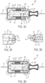
- Figures 3A and 3C are an isometric view and a top view of a sheathing tool 200, respectively, in a first position configured in accordance with embodiments of the present technology.
- Figures 3B and 3D are an isometric view and a top view of the sheathing tool 200, respectively, in a second position configured in accordance with embodiments of the present technology.
- the sheathing tool 200 may include a housing 202 having a first portion 212 and a second portion 222 slidably coupled to the first portion 212.
- the first portion 212 may include a first protrusion 210 and first arms 211 extending distally beyond the first protrusion 210
- the second portion 222 may include a second protrusion 220 and second arms 221 extending proximally beyond the second protrusion 220.
- the first and second arms 211, 221 can be coupled along at least a portion of their lengths and together surround an open interior region 208 of the housing 202 into which the first and second protrusions 210, 220 extend.
- the first and second protrusions 210, 220 are spaced apart from the adjacent first and second arms 211, 221.
- the first protrusion 210 is not spaced apart from the adjacent first arms 211.
- Figure 3E is an enlarged, isolated, cross-sectional view of a distal region of the first protrusion 210.
- the first protrusion 210 may include a first channel 216 extending distally from a proximal region of the proximal portion 212 of the housing 202 to a first opening 214.
- the first channel 216 is configured to receive the treatment device 10 in a constrained state therethrough, and the the first channel 216 is e configured to receive the sheath 19.
- the first sheath segment 31 is shown positioned within the first channel 216.
- the first channel 216 is surrounded by a generally tubular sidewall having an outer diameter OD1 that tapers in a distal direction.
- An inner diameter ID1 of the first channel 216 may taper distally to help guide the first element 17 in a generally constrained state towards the second opening 224.
- Figure 3F is an enlarged, isolated, cross-sectional view of a proximal region of the second protrusion 220.
- the second protrusion 220 may include a second channel 226 extending proximally from a distal region of the distal portion 222 of the housing 202 to a second opening 224.
- the second channel 226 is configured to receive the treatment device 10 in a constrained state therethrough, and the second channel 226 is configured to receive the sheath 19.
- the second sheath segment 33 is shown positioned within the second channel 226.
- the second channel 226 is by a generally tubular sidewall having an outer diameter OD2 that tapers in a proximal direction to facilitate positioning the second element 15 over the second protrusion 220.
- an inner diameter ID2 of the second channel 216 may taper distally to help guide and/or deflect the first element 17 into the second channel 226 and/or the second sheath segment 33.
- the first and second openings 214, 224 are spaced apart by a gap g having a first length
- first and second openings 214, 224 are spaced apart by a gap g having a second length less than the first length.
- the second length is great enough to allow the second element 15 to self-expand such that the second element 15 is positioned over the sidewall while the first element 17 generally maintains its diameter in the constrained state while crossing the gap g.
- the first element 17 does not have enough space between the first and second openings 214, 224 to expand, the first element 17 crosses the gap g in a constrained state which allows the first element 17 to enter through the second opening 224. If the gap g is too long, the distal ends of the first element 17 may begin to expand/splay outwardly and prevent the first element 17 from entering the second channel 226. Likewise, if the gap g is too short, the second element 15 may not have enough room for the distal portion 15b to flare radially outwardly to an extent that allows the second element 15 to extend over the second protrusion 222 and/or receive the second protrusion 222 within the lumen 27 ( Figure 2 ) of the distal region 15b.
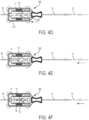
- Figures 4A-4H illustrate a method of using the sheathing tool 200 to sheath and/or re-sheath the treatment device 10.
- the treatment device 10 may first be withdrawn proximally from a treatment site through the blood vessel V lumen and catheter 100. Once removed from the catheter 100, the treatment device 10 may be in an expanded, unconstrained state in the second position such that the second element 15 is inverted over the first element 17. As shown in Figure 4B , the treatment device 10 in the second position may then be pulled proximally through the second sheath segment 33, then the sheathing tool 200, and into the first sheath segment 31.
- a proximal end of the elongated member 12 may be inserted into an opening at the distal portion 33b of the second segment 33, and the rest of the elongated member 12 may be pushed proximally through the second sheath segment 33, the sheathing tool 200, and at least a portion of the first sheath segment 31 (and/or pulled once the proximal end of the elongated member 12 exits a proximal portion 31a of the first sheath segment 31).
- the elongated member 12 may then be pushed distally, thereby advancing the first and second elements 17, 15 across the gap g, as shown in Figure 4C .
- the first element 17 may maintain its cross-sectional dimension in the constrained state while the second element 15 expands over the sidewall surrounding the second opening 224. (In Figure 4C , the first and second elements 17, 15 are shown in cross-section for ease of viewing the treatment device 10 within the gap g.)
- the first element 17 may be advanced across the gap g and into the second opening 224 while the sheathing tool 200 is in the first position.
- the first element 17 may only be advanced across a portion of the gap g (and not into the second opening 224) while the sheathing tool 200 remains in the first position.
- the first portion 212 of the housing 202 may be moved towards the second portion 222 of the housing 202 and secured in place by one or more detents and/or other securement features of the housing 202. Moving the first and second openings towards one another forces the second protrusion 220 further within the lumen of the second element 15. As shown in Figures 4E and 4F , the elongated member 12 can be pushed proximally while the sheathing tool 200 is in the second position, thereby advancing the first element 17 further within the second channel 126 and/or second sheath segment 33.
- the second element 15 extends further distally along the second protrusion 220 until it's fixed end portion pulls the second element 15 into the second channel 226.
- a portion of the second element may move in a first direction through the second channel while a second portion of the second element moves in a second direction opposite the first direction outside of the second channel 226.
- the second sheath segment 33 may then be coupled to the catheter 100.
- the elongated member 2 may be pushed proximally to transfer the treatment device 10 in the first position from the second sheath segment 33 to the catheter 100.
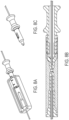
- Figures 5A and 5B are an isometric view and a top cross-sectional view, respectively, of a sheathing tool shown in a first position configured in accordance with some embodiments of the present technology.
- Figures 5C and 5D are an isometric view and a top cross-sectional view, respectively, of the sheathing tool shown in Figures 5A and 5B in a second position configured in accordance with some embodiments of the present technology.
- Figures 6A and 6B are a top view and a side cross-sectional view, respectively, of a sheathing tool 600 shown in a first position configured in accordance with some embodiments of the present technology.
- the housing 202 may be a single component and/or the first and second openings are spaced apart by a fixed distance.
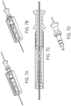
- Figure 7A is an isometric view of a sheathing tool in a first position configured in accordance with the present technology.
- Figure 7B is an isometric view of the sheathing tool of Figure 7A in a second position configured in accordance with the present technology
- Figure 7C is a side cross-sectional view of the sheathing tool as shown in Figure 7B.
- Figure 7D is an isometric view of the connector of the sheathing tool shown in Figures 7A-7C .
- Figure 8A is an isometric view of a sheathing tool in a first position configured in accordance with the present technology.
- Figure 8B is a side cross-sectional view of the sheathing tool of Figure 8A in a second position configured in accordance with the present technology.
- Figure 8C is an isometric view of the connector of the sheathing tool shown in Figures 8A and 8B .
- Figure 9A is an isometric view of a sheathing tool in a first position configured in accordance with the present technology.
- Figure 9B is an isometric view of the sheathing tool of Figure 7A in a second position configured in accordance with the present technology.
Landscapes
- Health & Medical Sciences (AREA)
- Life Sciences & Earth Sciences (AREA)
- Engineering & Computer Science (AREA)
- Biomedical Technology (AREA)
- Animal Behavior & Ethology (AREA)
- Veterinary Medicine (AREA)
- Public Health (AREA)
- Surgery (AREA)
- Heart & Thoracic Surgery (AREA)
- General Health & Medical Sciences (AREA)
- Vascular Medicine (AREA)
- Molecular Biology (AREA)
- Medical Informatics (AREA)
- Nuclear Medicine, Radiotherapy & Molecular Imaging (AREA)
- Orthopedic Medicine & Surgery (AREA)
- Biophysics (AREA)
- Pulmonology (AREA)
- Anesthesiology (AREA)
- Hematology (AREA)
- Cardiology (AREA)
- Oral & Maxillofacial Surgery (AREA)
- Transplantation (AREA)
- Surgical Instruments (AREA)
Description
- The present technology relates generally to sheathing tools and associated systems. Some embodiments of the present technology relate to devices for loading an intravascular treatment device into a sheath.
- Many medical procedures use medical device(s) to remove an obstruction (such as clot material) from a body lumen, vessel, or other organ. An inherent risk in such procedures is that mobilizing or otherwise disturbing the obstruction can potentially create further harm if the obstruction or a fragment thereof dislodges from the retrieval device. If all or a portion of the obstruction breaks free from the device and flows downstream, it is highly likely that the free material will become trapped in smaller and more tortuous anatomy. In many cases, the physician will no longer be able to use the same retrieval device to again remove the obstruction because the device may be too large and/or immobile to move the device to the site of the new obstruction.
- Even in successful procedures, a physician must be cautious to prevent the walls of the vessel or body lumen from imparting undesired forces to shear or dislodge the obstruction as it passes through the vasculature during removal. These forces have the potential of fragmenting the obstruction. In some cases, the obstruction can simply break free from the retrieval device and can lodge in a new area causing more concern than the original blockage.
- Procedures for treating ischemic stroke by restoring flow within the cerebral vasculature are subject to the above concerns. The brain relies on its arteries and veins to supply oxygenated blood from the heart and lungs and to remove carbon dioxide and cellular waste from brain tissue. Blockages that interfere with this blood supply eventually cause the brain tissue to stop functioning. If the disruption in blood occurs for a sufficient amount of time, the continued lack of nutrients and oxygen causes irreversible cell death (infarction). Accordingly, it is desirable to provide immediate medical treatment of an ischemic stroke. To access the cerebral vasculature, a physician typically advances a catheter from a remote part of the body (typically a leg) through the abdominal vasculature and into the cerebral region of the vasculature. Once within the cerebral vasculature, the physician deploys a device for retrieval of the obstruction causing the blockage. Concerns about dislodged obstructions or the migration of dislodged fragments increases the duration of the procedure at time when restoration of blood flow is paramount. Furthermore, a physician might be unaware of one or more fragments that dislodge from the initial obstruction and cause blockage of smaller more distal vessels.
- Many physicians currently perform thrombectomies (i.e. clot removal) with stents to resolve ischemic stroke. Typically, the physician deploys a stent into the clot in an attempt to push the clot to the side of the vessel and re-establish blood flow. Tissue plasminogen activator ("tPA") is often injected into the bloodstream through an intravenous line to break down a clot. However, it takes for the tPA to reach the clot because the tPA must travel through the vasculature and only begins to break up the clot once it reaches the clot material. tPA is also often administered to supplement the effectiveness of the stent. Yet, if attempts at clot dissolution are ineffective or incomplete, the physician can attempt to remove the stent while it is expanded against or enmeshed within the clot. In doing so, the physician must effectively drag the clot through the vasculature, in a proximal direction, into a guide catheter located within vessels in the patient's neck (typically the carotid artery). While this procedure has been shown to be effective in the clinic and easy for the physician to perform, there remain some distinct disadvantages using this approach.
- For example, one disadvantage is that the stent may not sufficiently retain the clot as it pulls the clot to the catheter. In such a case, some or all of the clot might remain the vasculature. Another risk is that as the stent mobilizes the clot from the original blockage site, the clot might not adhere to the stent as the stent is withdrawn toward the catheter. This is a particular risk when passing through bifurcations and tortuous anatomy. Furthermore, blood flow can carry the clot (or fragments of the clot) into a branching vessel at a bifurcation. If the clot is successfully brought to the end of the guide catheter in the carotid artery, yet another risk is that the clot may be "stripped" or "sheared" from the stent as the stent enters the guide catheter. Regardless, simply dragging an expanded stent (either fully or partially expanded) can result in undesired trauma to the vessel. In most cases, since the stent is oversized compared to the vessel, dragging a fixed metallic (or other) structure can pull the arteries and/or strip the cellular lining from the vessel, causing further trauma such as a hemorrhagic stroke (leakage of blood from a cerebral vessel). Also, the stent can become lodged on plaque on the vessel walls resulting in further vascular damage.
- In view of the above, there remains a need for improved devices and methods that can remove occlusions from body lumens and/or vessels.
US2014/309656 discloses a method for removing a kidney stone from a ureter.US2004/073243 discloses devices and methods for removing an obstruction from a blood vessel.US2014/005717 discloses structures for removing obstructions from body lumens. - The present invention is directed to a system as defined in claim 1. Further embodiments are recited in the dependent claims. At least some of the embodiments disclosed herein are devices, systems, and non-claimed methods for facilitating a user in positioning an expandable, intravascular treatment device within a lumen of a catheter and/or sheath. For example, certain medical procedures may require multiple passes of the same treatment device in order to effectively treat the patient. Between passes, the treatment device is often completely removed from the catheter and/or patient and must be re-loaded into the catheter for the next pass. For instance, removing clot material from a blood vessel of a patient may include advancing a clot retrieving device to a treatment site within the blood vessel lumen, capturing at least a portion of the clot material with the clot retrieving device, removing the clot material and clot retrieving device from the patient, then repeating the foregoing process until a sufficient amount of clot material is removed.
- Some embodiments of the present technology include a device for sheathing (and/or re-sheathing) a treatment device, such as a clot retrieving device. In some embodiments, the device includes a first channel and a second channel, each of which are configured to receive the treatment device in a constrained state therethrough. The first channel extends to a first opening and the second channel extends to a second opening that is surrounded by a sidewall. The second opening is spaced apart from the first opening by a gap, and the length of the gap is great enough to allow a first portion of the treatment device to self-expand over the sidewall while a second portion of the treatment device generally maintains its diameter in the constrained state while crossing the gap.
- Additional features and advantages of the subject technology are described below, and in part will be apparent from the description, or may be learned by practice of the subject technology. The advantages of the subject technology will be realized and attained by the structure particularly pointed out in the written description and claims hereof as well as the appended drawings.
- Many aspects of the present technology can be better understood with reference to the following drawings. The components in the drawings are not necessarily to scale. Instead, emphasis is placed on illustrating clearly the principles of the present disclosure.
-
Figure 1 is a schematic overview of a treatment system configured in accordance with the present technology. -
Figure 2 is a side view of a distal portion of the treatment device shown inFigure 1 in a second position in accordance with embodiments of the present technology. -
Figure 3A is an isometric view of a sheathing tool in a first position configured in accordance with the present technology. -
Figure 3B is an isometric view of the sheathing tool ofFigure 3A in a second position configured in accordance with the present technology. -
Figure 3C is a top view of the sheathing tool in the first position, as shown inFigure 3A . -
Figure 3D is a top view of the sheathing tool in the second position, as shown inFigure 3B . -
Figure 3E is an enlarged, isolated, cross-sectional view of the first channel shown inFigures 3A-3D . -
Figure 3F is an enlarged, isolated view, cross-sectional view of the second channel shown inFigures 3A-3D . -
Figures 4A-4H illustrate a method of using a sheathing tool to sheath a treatment device. -
Figures 5A and 5B are an isometric view and a top cross-sectional view, respectively, of a sheathing tool shown in a first position configured in accordance with some embodiments of the present technology. -
Figures 5C and 5D are an isometric view and a top cross-sectional view, respectively, of the sheathing tool shown inFigures 5A and 5B in a second position configured in accordance with some embodiments of the present technology. -
Figures 6A and 6B are a top view and a side cross-sectional view, respectively, of a sheathing tool shown in a first position configured in accordance with some embodiments of the present technology. -
Figure 7A is an isometric view of a sheathing tool in a first position configured in accordance with the present technology. -
Figure 7B is an isometric view of the sheathing tool ofFigure 7A in a second position configured in accordance with the present technology. -
Figure 7C is a side cross-sectional view of the sheathing tool as shown inFigure 7B . -
Figure 7D is an isometric view of the connector of the sheathing tool shown inFigures 7A-7C . -
Figure 8A is an isometric view of a sheathing tool in a first position configured in accordance with the present technology. -
Figure 8B is a side cross-sectional view of the sheathing tool ofFigure 8A in a second position configured in accordance with the present technology. -
Figure 8C is an isometric view of the connector of the sheathing tool shown inFigures 8A and 8B . -
Figure 9A is an isometric view of a sheathing tool in a first position configured in accordance with the present technology. -
Figure 9B is an isometric view of the sheathing tool ofFigure 7A in a second position configured in accordance with the present technology. - The present technology provides devices, systems, and non-claimed methods for sheathing and/or re-sheathing an intravascularly deliverable treatment device. Although many of the embodiments are described below with respect to devices, systems, and non-claimed methods for removing clot material/treating embolism (such as a cerebral embolism), the sheathing tools of the present technology may be used to re-sheath any intravascularly deliverable, expandable treatment device. Other applications and other embodiments in addition to those described herein are within the scope of the technology. For example, the sheathing tools of the present technology may be used with devices for removing emboli from body lumens other than blood vessels (e.g., the digestive tract, etc.) and/or may be used to remove emboli from blood vessels outside of the brain (e.g., pulmonary blood vessels, blood vessels within the legs, etc.). In addition, the sheathing tools of the present technology may be used with devices for removing luminal obstructions other than clot material (e.g., plaque, resected tissue, etc.).
-
Figure 1 is a schematic representation of a system 1 ("system 1") configured in accordance with the present technology. As shown inFigure 1 , the system 1 includes a treatment device 10 (shown in an expanded, unconstrained state), a catheter 100 (e.g., a microcatheter), a sheathing tool 200 (shown schematically), asupport 300, and asheath 19 for facilitating introduction of thetreatment device 10 to thecatheter 100 and/orsheathing tool 200. Thecatheter 100 may include ahandle 102 and anelongated shaft 104 having aproximal portion 104a coupled to thehandle 102 and adistal portion 104b configured to be positioned at a treatment site within a blood vessel lumen (e.g., a cerebral blood vessel lumen). Theelongated shaft 104 is configured to slidably receive thetreatment device 10 in a low-profile, constrained state (not shown) therethrough. - The
sheath 19 may be configured to be detachably coupled to thecatheter 100, thesheathing tool 200, and/or thesupport 300 and is configured to slidably receive thetreatment device 10 in a low-profile, constrained state (not shown) therethrough. In some embodiments, such as the embodiment shown inFigure 1 , thesheath 19 may include afirst segment 31 and asecond segment 33. Thefirst segment 31 may have aproximal portion 31a and adistal portion 31b configured to be detachably coupled to thesheathing tool 200, and thesecond segment 33 may have aproximal portion 33a configured to be detachably coupled to thesheathing tool 200 and adistal portion 33b configured to be detachably coupled to the handle 108 of thecatheter 100, thereby creating a pathway between the lumen of the second segment and the lumen of theelongated shaft 104. - As shown in
Figure 1 , thesheathing tool 200 and/or one or more portions of thesheath 19 may be configured to be detachably or permanently coupled to thesupport 300. For example, to secure thesheathing tool 200 and/or thesheath 19 to thesupport 300, thesupport 300 may include one or more tabs, slots, protrusions orother means 302 for engaging thesheath 19 and/or thesheathing tool 200 and/or one or more corresponding tabs, protrusions, slots, etc. on thesheath 19 and/or thesheathing tool 200. In some embodiments, the system 1 may be packaged with one or both of thesheathing tool 200 and thesheath 31 detachably or permanently mounted on thesupport 300. - The
treatment device 10 includes anelongated member 12 and atreatment assembly 14 coupled to a distal region of theelongated member 12. Thetreatment assembly 14 may be configured to be intravascularly positioned at or adjacent clot material within a blood vessel lumen and includes afirst element 17 and asecond element 15. In some embodiments, thefirst element 17 may be a self-expanding stent 17 (e.g., a laser-cut stent) and thesecond element 15 may be a self-expanding mesh (e.g., a braid, a weave, a lattice structure, a fabric, etc.). In some embodiments, the first andsecond elements - The
first element 17 has aproximal portion 17a coupled to theelongated member 12 and adistal portion 17b, and thesecond element 15 may have afree end portion 15b and afixed end portion 15a coupled to theelongated member 12. Thesecond element 15 may be flexible such that it is movable between a first position (Figure 1 ) in which itsfree end portion 15b is proximal of itsfixed end portion 15a, and a second position (seeFigure 2 ) in which thesecond element 15 is inverted over thefirst element 17 such that a distal terminus of thesecond element 15 is at or distal to the distal terminus of thefirst element 17. As shown inFigure 2 , when thesecond element 15 is in the second position, thefree end portion 15b is distal of thefixed end portion 15a and distal of the distal terminus of thefirst element 17. In the second position, thesecond element 15 may have a flareddistal region 25 that surround alumen 27 therethrough. - Examples of
suitable treatment devices 10 for use with the system 1 can be found inU.S. Patent Application No. 15/594,410, filed May 12, 2017 treatment device 10 shown inFigures 1 and2 , the sheathing tools disclosed herein may be utilized to sheath or re-sheath any expandable treatment device deliverable through a catheter. -
Figures 3A and3C are an isometric view and a top view of asheathing tool 200, respectively, in a first position configured in accordance with embodiments of the present technology.Figures 3B and3D are an isometric view and a top view of thesheathing tool 200, respectively, in a second position configured in accordance with embodiments of the present technology. Referring toFigures 3A-3D together, thesheathing tool 200 may include ahousing 202 having afirst portion 212 and asecond portion 222 slidably coupled to thefirst portion 212. Thefirst portion 212 may include afirst protrusion 210 andfirst arms 211 extending distally beyond thefirst protrusion 210, and thesecond portion 222 may include asecond protrusion 220 andsecond arms 221 extending proximally beyond thesecond protrusion 220. The first andsecond arms interior region 208 of thehousing 202 into which the first andsecond protrusions second protrusions second arms first protrusion 210 is not spaced apart from the adjacentfirst arms 211. -
Figure 3E is an enlarged, isolated, cross-sectional view of a distal region of thefirst protrusion 210. As shown inFigure 3E , thefirst protrusion 210 may include afirst channel 216 extending distally from a proximal region of theproximal portion 212 of thehousing 202 to afirst opening 214. Thefirst channel 216 is configured to receive thetreatment device 10 in a constrained state therethrough, and the thefirst channel 216 is e configured to receive thesheath 19. InFigure 3E , for example, thefirst sheath segment 31 is shown positioned within thefirst channel 216. Thefirst channel 216 is surrounded by a generally tubular sidewall having an outer diameter OD1 that tapers in a distal direction. An inner diameter ID1 of thefirst channel 216 may taper distally to help guide thefirst element 17 in a generally constrained state towards thesecond opening 224. -
Figure 3F is an enlarged, isolated, cross-sectional view of a proximal region of thesecond protrusion 220. As shown inFigure 3E , thesecond protrusion 220 may include asecond channel 226 extending proximally from a distal region of thedistal portion 222 of thehousing 202 to asecond opening 224. Thesecond channel 226 is configured to receive thetreatment device 10 in a constrained state therethrough, and thesecond channel 226 is configured to receive thesheath 19. InFigure 3F , for example, thesecond sheath segment 33 is shown positioned within thesecond channel 226. Thesecond channel 226 is by a generally tubular sidewall having an outer diameter OD2 that tapers in a proximal direction to facilitate positioning thesecond element 15 over thesecond protrusion 220. In some embodiments, an inner diameter ID2 of thesecond channel 216 may taper distally to help guide and/or deflect thefirst element 17 into thesecond channel 226 and/or thesecond sheath segment 33. - When the
sheathing tool 200 is in a first position, the first andsecond openings sheathing tool 200 is in a second position, the first andsecond openings second element 15 to self-expand such that thesecond element 15 is positioned over the sidewall while thefirst element 17 generally maintains its diameter in the constrained state while crossing the gap g. In other words, because thefirst element 17 does not have enough space between the first andsecond openings first element 17 crosses the gap g in a constrained state which allows thefirst element 17 to enter through thesecond opening 224. If the gap g is too long, the distal ends of thefirst element 17 may begin to expand/splay outwardly and prevent thefirst element 17 from entering thesecond channel 226. Likewise, if the gap g is too short, thesecond element 15 may not have enough room for thedistal portion 15b to flare radially outwardly to an extent that allows thesecond element 15 to extend over thesecond protrusion 222 and/or receive thesecond protrusion 222 within the lumen 27 (Figure 2 ) of thedistal region 15b. -
Figures 4A-4H illustrate a method of using thesheathing tool 200 to sheath and/or re-sheath thetreatment device 10. As shown inFigure 4A , in some embodiments thetreatment device 10 may first be withdrawn proximally from a treatment site through the blood vessel V lumen andcatheter 100. Once removed from thecatheter 100, thetreatment device 10 may be in an expanded, unconstrained state in the second position such that thesecond element 15 is inverted over thefirst element 17. As shown inFigure 4B , thetreatment device 10 in the second position may then be pulled proximally through thesecond sheath segment 33, then thesheathing tool 200, and into thefirst sheath segment 31. For example, a proximal end of theelongated member 12 may be inserted into an opening at thedistal portion 33b of thesecond segment 33, and the rest of theelongated member 12 may be pushed proximally through thesecond sheath segment 33, thesheathing tool 200, and at least a portion of the first sheath segment 31 (and/or pulled once the proximal end of theelongated member 12 exits aproximal portion 31a of the first sheath segment 31). Once a distal portion of thetreatment device 10 is aligned with or proximal of thefirst opening 214, theelongated member 12 may then be pushed distally, thereby advancing the first andsecond elements Figure 4C . While moving thetreatment device 10 across the gap, thefirst element 17 may maintain its cross-sectional dimension in the constrained state while thesecond element 15 expands over the sidewall surrounding thesecond opening 224. (InFigure 4C , the first andsecond elements treatment device 10 within the gap g.) In some embodiments, thefirst element 17 may be advanced across the gap g and into thesecond opening 224 while thesheathing tool 200 is in the first position. In some embodiments, thefirst element 17 may only be advanced across a portion of the gap g (and not into the second opening 224) while thesheathing tool 200 remains in the first position. - As shown in
Figure 4D , thefirst portion 212 of thehousing 202 may be moved towards thesecond portion 222 of thehousing 202 and secured in place by one or more detents and/or other securement features of thehousing 202. Moving the first and second openings towards one another forces thesecond protrusion 220 further within the lumen of thesecond element 15. As shown inFigures 4E and 4F , theelongated member 12 can be pushed proximally while thesheathing tool 200 is in the second position, thereby advancing thefirst element 17 further within the second channel 126 and/orsecond sheath segment 33. As theelongated member 12 is advanced distally, thesecond element 15 extends further distally along thesecond protrusion 220 until it's fixed end portion pulls thesecond element 15 into thesecond channel 226. As such, a portion of the second element may move in a first direction through the second channel while a second portion of the second element moves in a second direction opposite the first direction outside of thesecond channel 226. As shown inFigure 4G , thesecond sheath segment 33 may then be coupled to thecatheter 100. As shown inFigure 4H , the elongated member 2 may be pushed proximally to transfer thetreatment device 10 in the first position from thesecond sheath segment 33 to thecatheter 100. -
Figures 5A and 5B are an isometric view and a top cross-sectional view, respectively, of a sheathing tool shown in a first position configured in accordance with some embodiments of the present technology.Figures 5C and 5D are an isometric view and a top cross-sectional view, respectively, of the sheathing tool shown inFigures 5A and 5B in a second position configured in accordance with some embodiments of the present technology. -
Figures 6A and 6B are a top view and a side cross-sectional view, respectively, of a sheathing tool 600 shown in a first position configured in accordance with some embodiments of the present technology. In some embodiments, such as that shown inFigures 6A and 6B , thehousing 202 may be a single component and/or the first and second openings are spaced apart by a fixed distance. -
Figure 7A is an isometric view of a sheathing tool in a first position configured in accordance with the present technology.Figure 7B is an isometric view of the sheathing tool ofFigure 7A in a second position configured in accordance with the present technologyFigure 7C is a side cross-sectional view of the sheathing tool as shown inFigure 7B. Figure 7D is an isometric view of the connector of the sheathing tool shown inFigures 7A-7C . -
Figure 8A is an isometric view of a sheathing tool in a first position configured in accordance with the present technology.Figure 8B is a side cross-sectional view of the sheathing tool ofFigure 8A in a second position configured in accordance with the present technology.Figure 8C is an isometric view of the connector of the sheathing tool shown inFigures 8A and 8B . -
Figure 9A is an isometric view of a sheathing tool in a first position configured in accordance with the present technology.Figure 9B is an isometric view of the sheathing tool ofFigure 7A in a second position configured in accordance with the present technology. - This disclosure is not intended to be exhaustive or to limit the present technology to the precise forms disclosed herein. Although specific embodiments are disclosed herein for illustrative purposes, various equivalent modifications are possible without deviating from the the scope of the appended claims.
Claims (15)
- A system comprising:a treatment device (10) comprising an elongated member (12) having a proximal region and a distal region, the treatment device further comprising a first element (17) and a second element (15) at the distal region of the elongated member; anda device (200) for sheathing the treatment device, the device comprisinga first channel (216) extending to a first opening (214), the first channel configured to receive the treatment device in a constrained state therethrough; anda second channel (226) extending to a second opening (224), the second opening surrounded by a sidewall and configured to receive the treatment device in the constrained state therethrough, wherein the second opening is spaced apart from the first opening by a gap (g),and wherein a length of the gap is great enough to allow the second element to self-expand over the sidewall while the first element generally maintains its diameter in the constrained state while crossing the gap.
- The system of claim 1, wherein an inner diameter (ID2) of the second channel tapers distally from the second opening.
- The system of claim 1, wherein an outer diameter (OD2) of the sidewall increases distally from the second opening.
- The system of claim 1, wherein the first and second openings are fixed relative to one another such that the length of the gap is fixed.
- The system of claim 1, wherein the first and second openings are movable relative to one another such that the length of the gap is adjustable.
- The system of claim 1, wherein the first channel is within a first housing and the second channel is within a second housing movable relative to the first housing, and wherein the first housing has a detent configured to receive a protrusion of the second housing, or vice versa, such that the first housing is locked in place relative to the second housing.
- The system of claim 1, wherein the first channel is configured to receive a sheath (19) therethrough, wherein the sheath is configured to slidably receive the treatment device therein in the constrained state.
- The system of claim 1, wherein the second channel is configured to receive a sheath therethrough, and wherein the sheath is configured to slidably receive the treatment device therein in the constrained state.
- The system of claim 1, wherein the first element is a self-expanding element.
- The system of claim 1, wherein the second element is a self-expanding element.
- The system of claim 1, wherein the second element is a mesh.
- The system of claim 1, wherein the first element is a stent.
- The system of claim 1, wherein, in an expanded state, the second element has a flared distal region (25) with a lumen (27) therethrough, and wherein the lumen of the flared distal region is configured to receive the sidewall therein as the treatment device is moved through the across the gap.
- The system of claim 1, wherein the treatment device is a clot retrieving device.
- The system of claim 1, wherein the device is configured to be detachably coupled to a handle (102) of a catheter (100), thereby placing the second channel in fluid communication with a lumen of the catheter.
Applications Claiming Priority (2)
| Application Number | Priority Date | Filing Date | Title |
|---|---|---|---|
| US201762518586P | 2017-06-12 | 2017-06-12 | |
| PCT/US2018/037418 WO2018232044A1 (en) | 2017-06-12 | 2018-06-13 | Tools for sheathing treatment devices and associated systems and methods |
Publications (3)
| Publication Number | Publication Date |
|---|---|
| EP3638134A1 EP3638134A1 (en) | 2020-04-22 |
| EP3638134A4 EP3638134A4 (en) | 2021-01-06 |
| EP3638134B1 true EP3638134B1 (en) | 2023-08-16 |
Family
ID=64562738
Family Applications (1)
| Application Number | Title | Priority Date | Filing Date |
|---|---|---|---|
| EP18818050.9A Active EP3638134B1 (en) | 2017-06-12 | 2018-06-13 | Tools for sheathing treatment devices and associated systems |
Country Status (4)
| Country | Link |
|---|---|
| US (2) | US10945746B2 (en) |
| EP (1) | EP3638134B1 (en) |
| CN (1) | CN110831523B (en) |
| WO (1) | WO2018232044A1 (en) |
Families Citing this family (8)
| Publication number | Priority date | Publication date | Assignee | Title |
|---|---|---|---|---|
| ES2577288B8 (en) | 2015-01-13 | 2019-01-10 | Anaconda Biomed S L | Device for thrombectomy |
| US11771446B2 (en) | 2020-10-19 | 2023-10-03 | Anaconda Biomed, S.L. | Thrombectomy system and method of use |
| US12575845B2 (en) | 2015-12-11 | 2026-03-17 | Anaconda Biomed, S.L. | Thrombectomy device, system and method for extraction of vascular thrombi from a blood vessel |
| EP3639768A1 (en) | 2018-10-16 | 2020-04-22 | Anaconda Biomed, S.L. | A device for extraction of thrombus from a blood vessel and a thrombectomy apparatus |
| WO2018232044A1 (en) | 2017-06-12 | 2018-12-20 | Covidien Lp | Tools for sheathing treatment devices and associated systems and methods |
| US12569264B2 (en) | 2018-10-16 | 2026-03-10 | Anaconda Biomed, S.L. | Device and a thrombectomy apparatus for extraction of thrombus from a blood vessel |
| EP3908212B1 (en) * | 2019-01-11 | 2023-03-22 | Anaconda Biomed, S.L. | Loading device for loading a medical device into a catheter |
| JP2025501729A (en) | 2021-12-21 | 2025-01-23 | アナコンダ ビオメッド, エス.エル. | Intravascular device with improved attachment of its components and method of manufacture |
Family Cites Families (316)
| Publication number | Priority date | Publication date | Assignee | Title |
|---|---|---|---|---|
| US2943626A (en) | 1957-01-31 | 1960-07-05 | Dormia Enrico | Instruments for the extraction of foreign bodies |
| US2918919A (en) | 1957-04-19 | 1959-12-29 | American Cystoscope Makers Inc | Combined ureteral stone remover and drain |
| US3996938A (en) | 1975-07-10 | 1976-12-14 | Clark Iii William T | Expanding mesh catheter |
| DE2900585A1 (en) | 1979-01-09 | 1980-07-17 | Handtmann Albert Gmbh & Co | METHOD AND ARRANGEMENT FOR THE FOLLOWING PORTIONING OF A PLASTICALLY DEFORMABLE DIMENSION, IN PARTICULAR SAUSAGE DIMENSION |
| IT1126526B (en) | 1979-12-07 | 1986-05-21 | Enrico Dormia | SURGICAL EXTRACTOR TO REMOVE FOREIGN BODIES THAT ARE FOUND IN THE NATURAL ROUTES OF THE HUMAN BODY, AS CALCULATIONS AND SIMILAR |
| US4611594A (en) | 1984-04-11 | 1986-09-16 | Northwestern University | Medical instrument for containment and removal of calculi |
| DE3501707C2 (en) | 1985-01-19 | 1987-01-02 | Georg 3008 Garbsen Pauldrach | Device for recovering or dissecting concretions formed in human hollow organs |
| US4807626A (en) | 1985-02-14 | 1989-02-28 | Mcgirr Douglas B | Stone extractor and method |
| EP0200668A3 (en) | 1985-04-25 | 1988-03-09 | FOGARTY, Thomas J. | Apparatus and method for dislodging and removing occlusive objects from body passages |
| US4657020A (en) | 1985-07-10 | 1987-04-14 | Jayco Pharmaceuticals | Method of using a foreign object protector hood |
| US4699147A (en) | 1985-09-25 | 1987-10-13 | Cordis Corporation | Intraventricular multielectrode cardial mapping probe and method for using same |
| US4650466A (en) | 1985-11-01 | 1987-03-17 | Angiobrade Partners | Angioplasty device |
| US4790812A (en) | 1985-11-15 | 1988-12-13 | Hawkins Jr Irvin F | Apparatus and method for removing a target object from a body passsageway |
| US4873978A (en) | 1987-12-04 | 1989-10-17 | Robert Ginsburg | Device and method for emboli retrieval |
| FR2624747A1 (en) | 1987-12-18 | 1989-06-23 | Delsanti Gerard | REMOVABLE ENDO-ARTERIAL DEVICES FOR REPAIRING ARTERIAL WALL DECOLLEMENTS |
| US4832055A (en) | 1988-07-08 | 1989-05-23 | Palestrant Aubrey M | Mechanically locking blood clot filter |
| JPH0255064A (en) | 1988-08-03 | 1990-02-23 | Toa O | Skin removal for throm bus in blood vessel using catheter and throm bus removing system in blood vessel using catheter |
| US5152777A (en) | 1989-01-25 | 1992-10-06 | Uresil Corporation | Device and method for providing protection from emboli and preventing occulsion of blood vessels |
| US4969891A (en) | 1989-03-06 | 1990-11-13 | Gewertz Bruce L | Removable vascular filter |
| US5147400A (en) | 1989-05-10 | 1992-09-15 | United States Surgical Corporation | Connective tissue prosthesis |
| DE8910603U1 (en) | 1989-09-06 | 1989-12-07 | Günther, Rolf W., Prof. Dr. | Device for removing blood clots from arteries and veins |
| US5034001A (en) | 1989-09-08 | 1991-07-23 | Advanced Cardiovascular Systems, Inc. | Method of repairing a damaged blood vessel with an expandable cage catheter |
| FR2657261A1 (en) | 1990-01-19 | 1991-07-26 | Bovyn Gilles | Device for temporary implantation of a blood filter in a vein of the human body |
| CA2048307C (en) | 1990-08-14 | 1998-08-18 | Rolf Gunther | Method and apparatus for filtering blood in a blood vessel of a patient |
| US5057114A (en) | 1990-09-18 | 1991-10-15 | Cook Incorporated | Medical retrieval basket |
| US5449372A (en) | 1990-10-09 | 1995-09-12 | Scimed Lifesystems, Inc. | Temporary stent and methods for use and manufacture |
| US5192286A (en) | 1991-07-26 | 1993-03-09 | Regents Of The University Of California | Method and device for retrieving materials from body lumens |
| US5509900A (en) | 1992-03-02 | 1996-04-23 | Kirkman; Thomas R. | Apparatus and method for retaining a catheter in a blood vessel in a fixed position |
| AU682003B2 (en) | 1992-06-26 | 1997-09-18 | Schneider (Usa) Inc. | Catheter with expandable wire mesh tip |
| US5443478A (en) | 1992-09-02 | 1995-08-22 | Board Of Regents, The University Of Texas System | Multi-element intravascular occlusion device |
| US5336178A (en) | 1992-11-02 | 1994-08-09 | Localmed, Inc. | Intravascular catheter with infusion array |
| US5490859A (en) | 1992-11-13 | 1996-02-13 | Scimed Life Systems, Inc. | Expandable intravascular occlusion material removal devices and methods of use |
| CA2156517C (en) | 1993-02-19 | 2001-08-28 | James S. Bates | Surgical extractor |
| US5643309A (en) | 1993-03-25 | 1997-07-01 | Myler; Richard | Cardiovascular stent and retrieval apparatus |
| WO1995009586A1 (en) | 1993-10-01 | 1995-04-13 | Emory University | Self-expanding intraluminal composite prosthesis |
| US5458375A (en) | 1994-04-25 | 1995-10-17 | The Anspach Effort, Inc. | Rotary connector for fluid conduits |
| WO2000053120A1 (en) | 1994-07-08 | 2000-09-14 | Microvena Corporation | Minimally invasive medical device deployment and retrieval system |
| DE69529338T3 (en) | 1994-07-08 | 2007-05-31 | Ev3 Inc., Plymouth | Intravascular filter device |
| US5658296A (en) | 1994-11-21 | 1997-08-19 | Boston Scientific Corporation | Method for making surgical retrieval baskets |
| US5709704A (en) | 1994-11-30 | 1998-01-20 | Boston Scientific Corporation | Blood clot filtering |
| US5549626A (en) | 1994-12-23 | 1996-08-27 | New York Society For The Ruptured And Crippled Maintaining The Hospital For Special Surgery | Vena caval filter |
| US6350266B1 (en) | 1995-02-02 | 2002-02-26 | Scimed Life Systems, Inc. | Hybrid stone retrieval device |
| US6348056B1 (en) | 1999-08-06 | 2002-02-19 | Scimed Life Systems, Inc. | Medical retrieval device with releasable retrieval basket |
| CA2212084C (en) | 1995-02-02 | 2008-11-18 | Boston Scientific Corporation | Surgical wire basket extractor |
| FR2735967B1 (en) | 1995-06-27 | 1998-03-06 | Perouse Implant Lab | VASCULAR SURGERY TOOL AND ITS USE |
| US6168622B1 (en) | 1996-01-24 | 2001-01-02 | Microvena Corporation | Method and apparatus for occluding aneurysms |
| US5895398A (en) | 1996-02-02 | 1999-04-20 | The Regents Of The University Of California | Method of using a clot capture coil |
| IL125417A (en) | 1996-02-02 | 2004-03-28 | Transvascular Inc | Apparatus for blocking flow through blood vessels |
| US5971938A (en) | 1996-04-02 | 1999-10-26 | Hart; Charles C. | Access device with expandable containment member |
| US5846251A (en) | 1996-07-22 | 1998-12-08 | Hart; Charles C. | Access device with expandable containment member |
| US6096053A (en) | 1996-05-03 | 2000-08-01 | Scimed Life Systems, Inc. | Medical retrieval basket |
| US6800080B1 (en) | 1996-05-03 | 2004-10-05 | Scimed Life Systems, Inc. | Medical retrieval device |
| IT241710Y1 (en) | 1996-06-20 | 2001-05-17 | Fina Ernesto | DEVICE FOR ENDOCAVITARY ELECTROLYSIS OF URINE CALCULATIONS OELECTROLITOLYSIS |
| US5662671A (en) | 1996-07-17 | 1997-09-02 | Embol-X, Inc. | Atherectomy device having trapping and excising means for removal of plaque from the aorta and other arteries |
| US6066158A (en) | 1996-07-25 | 2000-05-23 | Target Therapeutics, Inc. | Mechanical clot encasing and removal wire |
| US5972019A (en) | 1996-07-25 | 1999-10-26 | Target Therapeutics, Inc. | Mechanical clot treatment device |
| US6391044B1 (en) | 1997-02-03 | 2002-05-21 | Angioguard, Inc. | Vascular filter system |
| US5882329A (en) | 1997-02-12 | 1999-03-16 | Prolifix Medical, Inc. | Apparatus and method for removing stenotic material from stents |
| US5814064A (en) | 1997-03-06 | 1998-09-29 | Scimed Life Systems, Inc. | Distal protection device |
| US5827324A (en) | 1997-03-06 | 1998-10-27 | Scimed Life Systems, Inc. | Distal protection device |
| US5911710A (en) * | 1997-05-02 | 1999-06-15 | Schneider/Namic | Medical insertion device with hemostatic valve |
| US5980554A (en) | 1997-05-05 | 1999-11-09 | Micro Therapeutics, Inc. | Wire frame partial flow obstruction for aneurysm treatment |
| US5911734A (en) | 1997-05-08 | 1999-06-15 | Embol-X, Inc. | Percutaneous catheter and guidewire having filter and medical device deployment capabilities |
| US5836966A (en) | 1997-05-22 | 1998-11-17 | Scimed Life Systems, Inc. | Variable expansion force stent |
| US5947995A (en) | 1997-06-06 | 1999-09-07 | Samuels; Shaun Lawrence Wilkie | Method and apparatus for removing blood clots and other objects |
| JP3527619B2 (en) | 1997-06-25 | 2004-05-17 | ペンタックス株式会社 | Endoscope stent |
| US6245088B1 (en) | 1997-07-07 | 2001-06-12 | Samuel R. Lowery | Retrievable umbrella sieve and method of use |
| US5984957A (en) | 1997-08-12 | 1999-11-16 | Schneider (Usa) Inc | Radially expanded prostheses with axial diameter control |
| US5968090A (en) | 1997-09-08 | 1999-10-19 | United States Surgical Corp. | Endovascular graft and method |
| US6066149A (en) | 1997-09-30 | 2000-05-23 | Target Therapeutics, Inc. | Mechanical clot treatment device with distal filter |
| US6174318B1 (en) | 1998-04-23 | 2001-01-16 | Scimed Life Systems, Inc. | Basket with one or more moveable legs |
| US6099534A (en) | 1997-10-01 | 2000-08-08 | Scimed Life Systems, Inc. | Releasable basket |
| US6416505B1 (en) | 1998-05-05 | 2002-07-09 | Scimed Life Systems, Inc. | Surgical method and apparatus for positioning a diagnostic or therapeutic element within the body and pressure application probe for use with same |
| CA2450927C (en) | 1997-11-07 | 2007-11-06 | Salviac Limited | An embolic protection device |
| US6635068B1 (en) | 1998-02-10 | 2003-10-21 | Artemis Medical, Inc. | Occlusion, anchoring, tensioning and flow direction apparatus and methods for use |
| US6238412B1 (en) | 1997-11-12 | 2001-05-29 | William Dubrul | Biological passageway occlusion removal |
| US6221006B1 (en) | 1998-02-10 | 2001-04-24 | Artemis Medical Inc. | Entrapping apparatus and method for use |
| US6443972B1 (en) | 1997-11-19 | 2002-09-03 | Cordis Europa N.V. | Vascular filter |
| US6033394A (en) | 1997-12-05 | 2000-03-07 | Intratherapeutics, Inc. | Catheter support structure |
| US6602265B2 (en) | 1998-02-10 | 2003-08-05 | Artemis Medical, Inc. | Tissue separation medical device and method |
| US6383195B1 (en) | 1998-04-13 | 2002-05-07 | Endoline, Inc. | Laparoscopic specimen removal apparatus |
| US6511492B1 (en) | 1998-05-01 | 2003-01-28 | Microvention, Inc. | Embolectomy catheters and methods for treating stroke and other small vessel thromboembolic disorders |
| CA2334223C (en) | 1998-06-04 | 2008-11-18 | New York University | Endovascular thin film devices and methods for treating and preventing stroke |
| US6217609B1 (en) | 1998-06-30 | 2001-04-17 | Schneider (Usa) Inc | Implantable endoprosthesis with patterned terminated ends and methods for making same |
| US6656218B1 (en) | 1998-07-24 | 2003-12-02 | Micrus Corporation | Intravascular flow modifier and reinforcement device |
| EP1148839B1 (en) | 1999-02-01 | 2008-09-10 | Board Of Regents, The University Of Texas System | Woven bifurcated and trifurcated stents and methods for making the same |
| US7018401B1 (en) | 1999-02-01 | 2006-03-28 | Board Of Regents, The University Of Texas System | Woven intravascular devices and methods for making the same and apparatus for delivery of the same |
| US20020138094A1 (en) | 1999-02-12 | 2002-09-26 | Thomas Borillo | Vascular filter system |
| US20020169474A1 (en) | 1999-03-08 | 2002-11-14 | Microvena Corporation | Minimally invasive medical device deployment and retrieval system |
| US6159220A (en) | 1999-03-11 | 2000-12-12 | Scimed Life Systems, Inc. | Medical retrieval device |
| US6964672B2 (en) | 1999-05-07 | 2005-11-15 | Salviac Limited | Support frame for an embolic protection device |
| US6375668B1 (en) | 1999-06-02 | 2002-04-23 | Hanson S. Gifford | Devices and methods for treating vascular malformations |
| US6458139B1 (en) | 1999-06-21 | 2002-10-01 | Endovascular Technologies, Inc. | Filter/emboli extractor for use in variable sized blood vessels |
| US6616679B1 (en) | 1999-07-30 | 2003-09-09 | Incept, Llc | Rapid exchange vascular device for emboli and thrombus removal and methods of use |
| US20020026211A1 (en) | 1999-12-23 | 2002-02-28 | Farhad Khosravi | Vascular device having emboli and thrombus removal element and methods of use |
| US6142987A (en) | 1999-08-03 | 2000-11-07 | Scimed Life Systems, Inc. | Guided filter with support wire and methods of use |
| US6168579B1 (en) | 1999-08-04 | 2001-01-02 | Scimed Life Systems, Inc. | Filter flush system and methods of use |
| US6454775B1 (en) | 1999-12-06 | 2002-09-24 | Bacchus Vascular Inc. | Systems and methods for clot disruption and retrieval |
| US6364895B1 (en) | 1999-10-07 | 2002-04-02 | Prodesco, Inc. | Intraluminal filter |
| US6425909B1 (en) | 1999-11-04 | 2002-07-30 | Concentric Medical, Inc. | Methods and devices for filtering fluid flow through a body structure |
| US6190394B1 (en) | 1999-11-05 | 2001-02-20 | Annex Medical, Inc. | Medical retrieval basket |
| US6371971B1 (en) | 1999-11-15 | 2002-04-16 | Scimed Life Systems, Inc. | Guidewire filter and methods of use |
| US6645199B1 (en) | 1999-11-22 | 2003-11-11 | Scimed Life Systems, Inc. | Loop structures for supporting diagnostic and therapeutic elements contact with body tissue and expandable push devices for use with same |
| US6673042B1 (en) | 1999-11-22 | 2004-01-06 | Wilfred J. Samson | Expandable venous cannula and method of use |
| US6745080B2 (en) | 1999-11-22 | 2004-06-01 | Scimed Life Systems, Inc. | Helical and pre-oriented loop structures for supporting diagnostic and therapeutic elements in contact with body tissue |
| US6402771B1 (en) | 1999-12-23 | 2002-06-11 | Guidant Endovascular Solutions | Snare |
| US6575997B1 (en) | 1999-12-23 | 2003-06-10 | Endovascular Technologies, Inc. | Embolic basket |
| US6660021B1 (en) | 1999-12-23 | 2003-12-09 | Advanced Cardiovascular Systems, Inc. | Intravascular device and system |
| US6702834B1 (en) | 1999-12-30 | 2004-03-09 | Advanced Cardiovascular Systems, Inc. | Embolic protection devices |
| DE10000137A1 (en) | 2000-01-04 | 2001-07-12 | Pfm Prod Fuer Die Med Ag | Implantate for closing defect apertures in human or animal bodies, bearing structure of which can be reversed from secondary to primary form by elastic force |
| US6325822B1 (en) | 2000-01-31 | 2001-12-04 | Scimed Life Systems, Inc. | Braided stent having tapered filaments |
| US6540768B1 (en) | 2000-02-09 | 2003-04-01 | Cordis Corporation | Vascular filter system |
| US6344044B1 (en) | 2000-02-11 | 2002-02-05 | Edwards Lifesciences Corp. | Apparatus and methods for delivery of intraluminal prosthesis |
| ES2215888T3 (en) | 2000-03-10 | 2004-10-16 | Radius Medical Technologies, Inc. | SURGICAL HITCH DEVICE. |
| US6264664B1 (en) | 2000-03-10 | 2001-07-24 | General Science And Technology Corp. | Surgical basket devices |
| DE60126585T2 (en) | 2000-03-10 | 2007-12-06 | Anthony T. Bakersfield Don Michael | Device for the prevention of vascular embolism |
| US6514273B1 (en) | 2000-03-22 | 2003-02-04 | Endovascular Technologies, Inc. | Device for removal of thrombus through physiological adhesion |
| US20010031981A1 (en) | 2000-03-31 | 2001-10-18 | Evans Michael A. | Method and device for locating guidewire and treating chronic total occlusions |
| US6592616B1 (en) | 2000-04-28 | 2003-07-15 | Advanced Cardiovascular Systems, Inc. | System and device for minimizing embolic risk during an interventional procedure |
| US6602271B2 (en) | 2000-05-24 | 2003-08-05 | Medtronic Ave, Inc. | Collapsible blood filter with optimal braid geometry |
| US6939362B2 (en) | 2001-11-27 | 2005-09-06 | Advanced Cardiovascular Systems, Inc. | Offset proximal cage for embolic filtering devices |
| US6663650B2 (en) | 2000-06-29 | 2003-12-16 | Concentric Medical, Inc. | Systems, methods and devices for removing obstructions from a blood vessel |
| US20040073243A1 (en) | 2000-06-29 | 2004-04-15 | Concentric Medical, Inc., A Delaware Corporation | Systems, methods and devices for removing obstructions from a blood vessel |
| US6730104B1 (en) | 2000-06-29 | 2004-05-04 | Concentric Medical, Inc. | Methods and devices for removing an obstruction from a blood vessel |
| US7766921B2 (en) | 2000-06-29 | 2010-08-03 | Concentric Medical, Inc. | Systems, methods and devices for removing obstructions from a blood vessel |
| US7285126B2 (en) | 2000-06-29 | 2007-10-23 | Concentric Medical, Inc. | Systems, methods and devices for removing obstructions from a blood vessel |
| US8298257B2 (en) | 2000-06-29 | 2012-10-30 | Concentric Medical, Inc. | Systems, methods and devices for removing obstructions from a blood vessel |
| CA2411699A1 (en) | 2000-06-29 | 2002-01-10 | Ivan Sepetka | Systems, methods and devices for removing obstructions from a blood vessel |
| US6824545B2 (en) | 2000-06-29 | 2004-11-30 | Concentric Medical, Inc. | Systems, methods and devices for removing obstructions from a blood vessel |
| US7727242B2 (en) | 2000-06-29 | 2010-06-01 | Concentric Medical, Inc. | Systems, methods and devices for removing obstructions from a blood vessel |
| US7727243B2 (en) | 2000-06-29 | 2010-06-01 | Concentric Medical., Inc. | Systems, methods and devices for removing obstructions from a blood vessel |
| FR2813518B1 (en) | 2000-09-04 | 2002-10-31 | Claude Mialhe | VASCULAR OCCLUSION DEVICE, APPARATUS AND METHOD OF USE |
| US6500185B1 (en) | 2000-09-29 | 2002-12-31 | Primus Medical, Inc. | Snare device |
| US20020058904A1 (en) | 2000-11-08 | 2002-05-16 | Robert Boock | Thrombus removal device |
| US6679893B1 (en) | 2000-11-16 | 2004-01-20 | Chestnut Medical Technologies, Inc. | Grasping device and method of use |
| US6540657B2 (en) | 2000-12-28 | 2003-04-01 | Scimed Life Systems, Inc. | Apparatus and method for internally inducing a magnetic field in an aneurysm to embolize aneurysm with magnetically-controllable substance |
| JP5102931B2 (en) | 2001-01-09 | 2012-12-19 | マイクロベンション インコーポレイテッド | Embolization catheter and system having the catheter |
| US7018394B2 (en) | 2001-01-10 | 2006-03-28 | Cordis Neurovascular, Inc. | Embolic coil introducer system |
| US7169165B2 (en) | 2001-01-16 | 2007-01-30 | Boston Scientific Scimed, Inc. | Rapid exchange sheath for deployment of medical devices and methods of use |
| US6936059B2 (en) | 2001-01-16 | 2005-08-30 | Scimed Life Systems, Inc. | Endovascular guidewire filter and methods of use |
| US6610077B1 (en) | 2001-01-23 | 2003-08-26 | Endovascular Technologies, Inc. | Expandable emboli filter and thrombectomy device |
| US20020128680A1 (en) | 2001-01-25 | 2002-09-12 | Pavlovic Jennifer L. | Distal protection device with electrospun polymer fiber matrix |
| US6494884B2 (en) | 2001-02-09 | 2002-12-17 | Concentric Medical, Inc. | Methods and devices for delivering occlusion elements |
| US6585753B2 (en) | 2001-03-28 | 2003-07-01 | Scimed Life Systems, Inc. | Expandable coil stent |
| US6636758B2 (en) | 2001-05-01 | 2003-10-21 | Concentric Medical, Inc. | Marker wire and process for using it |
| US20020188314A1 (en) | 2001-06-07 | 2002-12-12 | Microvena Corporation | Radiopaque distal embolic protection device |
| US6793665B2 (en) | 2001-06-18 | 2004-09-21 | Rex Medical, L.P. | Multiple access vein filter |
| US6638245B2 (en) | 2001-06-26 | 2003-10-28 | Concentric Medical, Inc. | Balloon catheter |
| US6702782B2 (en) | 2001-06-26 | 2004-03-09 | Concentric Medical, Inc. | Large lumen balloon catheter |
| US7640952B2 (en) | 2001-06-28 | 2010-01-05 | Lithotech Medical Ltd. | Method for manufacturing a surgical device for extracting a foreign object |
| WO2003002006A1 (en) | 2001-06-28 | 2003-01-09 | Lithotech Medical Ltd. | Foreign body retrieval device |
| IL144213A0 (en) | 2001-07-09 | 2002-05-23 | Mind Guard Ltd | Implantable filter |
| ES2264468T3 (en) | 2001-07-13 | 2007-01-01 | B. Braun Medical Sas | VASCULAR PROTECTION SYSTEM AND ANGIOPLASTIA APPARATUS EQUIPPED. |
| US6551342B1 (en) | 2001-08-24 | 2003-04-22 | Endovascular Technologies, Inc. | Embolic filter |
| US6893431B2 (en) | 2001-10-15 | 2005-05-17 | Scimed Life Systems, Inc. | Medical device for delivering patches |
| US20040138692A1 (en) | 2003-01-13 | 2004-07-15 | Scimed Life Systems, Inc. | Embolus extractor |
| US6989020B2 (en) | 2001-11-15 | 2006-01-24 | Cordis Neurovascular, Inc. | Embolic coil retrieval system |
| US6755813B2 (en) | 2001-11-20 | 2004-06-29 | Cleveland Clinic Foundation | Apparatus and method for performing thrombolysis |
| US6749619B2 (en) | 2001-11-20 | 2004-06-15 | The Cleveland Clinic Foundation | Apparatus and method for eliminating dislodged thrombus |
| US7488313B2 (en) | 2001-11-29 | 2009-02-10 | Boston Scientific Scimed, Inc. | Mechanical apparatus and method for dilating and delivering a therapeutic agent to a site of treatment |
| US7182771B1 (en) | 2001-12-20 | 2007-02-27 | Russell A. Houser | Vascular couplers, techniques, methods, and accessories |
| WO2003055412A2 (en) | 2001-12-21 | 2003-07-10 | Salviac Limited | A support frame for an embolic protection device |
| US20030176884A1 (en) | 2002-03-12 | 2003-09-18 | Marwane Berrada | Everted filter device |
| US6953465B2 (en) | 2002-03-25 | 2005-10-11 | Concentric Medical, Inc. | Containers and methods for delivering vaso-occluding filaments and particles |
| DE10217757A1 (en) | 2002-04-20 | 2003-10-30 | Friedhelm Brassel | Medical retriever |
| US6852254B2 (en) | 2002-06-26 | 2005-02-08 | Johnson & Johnson Vision Care, Inc. | Methods for the production of tinted contact lenses |
| US20040172056A1 (en) | 2002-07-12 | 2004-09-02 | Guterman Lee R. | Bifurcated aneurysm buttress arrangement |
| US7058456B2 (en) | 2002-08-09 | 2006-06-06 | Concentric Medical, Inc. | Methods and devices for changing the shape of a medical device |
| DE10242444A1 (en) | 2002-09-11 | 2004-04-01 | pfm Produkte für die Medizin AG | extractor |
| US7220271B2 (en) | 2003-01-30 | 2007-05-22 | Ev3 Inc. | Embolic filters having multiple layers and controlled pore size |
| US20040153025A1 (en) | 2003-02-03 | 2004-08-05 | Seifert Paul S. | Systems and methods of de-endothelialization |
| US20040199201A1 (en) | 2003-04-02 | 2004-10-07 | Scimed Life Systems, Inc. | Embolectomy devices |
| US7122003B2 (en) | 2003-04-16 | 2006-10-17 | Granit Medical Innovations, Llc | Endoscopic retractor instrument and associated method |
| KR100561713B1 (en) | 2003-05-23 | 2006-03-20 | (주) 태웅메디칼 | Method for manufacturing a variable state stent and a variable state stent produced thereby |
| US20050004594A1 (en) | 2003-07-02 | 2005-01-06 | Jeffrey Nool | Devices and methods for aspirating from filters |
| US7879062B2 (en) | 2003-07-22 | 2011-02-01 | Lumen Biomedical, Inc. | Fiber based embolism protection device |
| US7731722B2 (en) | 2003-07-31 | 2010-06-08 | Vance Products Incorporated | Ureteral backstop filter and retrieval device |
| US7316692B2 (en) | 2003-08-12 | 2008-01-08 | Boston Scientific Scimed, Inc. | Laser-cut clot puller |
| JP2007503918A (en) | 2003-09-04 | 2007-03-01 | セカント メディカル エルエルシー | Intravascular snare for capturing and removing arterial emboli |
| US7371248B2 (en) | 2003-10-14 | 2008-05-13 | Medtronic Vascular, Inc. | Steerable distal protection guidewire and methods of use |
| US20050085826A1 (en) | 2003-10-21 | 2005-04-21 | Scimed Life Systems, Inc. | Unfolding balloon catheter for proximal embolus protection |
| JP2005160648A (en) | 2003-12-01 | 2005-06-23 | Terumo Corp | Intravascular foreign matter removal wire and medical device |
| US7354445B2 (en) | 2003-12-15 | 2008-04-08 | Medtronic Vascular Inc. | Embolic containment system with asymmetric frictional control |
| DE602005011575D1 (en) | 2004-02-19 | 2009-01-22 | Applied Med Resources | Embolectomy CATCH LOCK |
| WO2005081949A2 (en) | 2004-02-24 | 2005-09-09 | Board Of Regents, The University Of Texas System | Foreign body retrieval devices |
| US20070118165A1 (en) | 2004-03-08 | 2007-05-24 | Demello Jonathan R | System and method for removal of material from a blood vessel using a small diameter catheter |
| US8777974B2 (en) | 2004-03-19 | 2014-07-15 | Aga Medical Corporation | Multi-layer braided structures for occluding vascular defects |
| US7686825B2 (en) | 2004-03-25 | 2010-03-30 | Hauser David L | Vascular filter device |
| US20050234501A1 (en) | 2004-04-15 | 2005-10-20 | Barone David D | Braided intraluminal filter |
| US8267985B2 (en) | 2005-05-25 | 2012-09-18 | Tyco Healthcare Group Lp | System and method for delivering and deploying an occluding device within a vessel |
| WO2005123171A2 (en) | 2004-06-09 | 2005-12-29 | Stout Medical Group Lp | Three-dimensional coils for treatment of vascular aneurysms |
| US20050283166A1 (en) | 2004-06-17 | 2005-12-22 | Secant Medical, Llc | Expandible snare |
| US7462183B2 (en) | 2004-07-07 | 2008-12-09 | Percutaneous Systems, Inc. | Methods for deploying conformed structures in body lumens |
| US7240516B2 (en) | 2004-08-03 | 2007-07-10 | Medtronic Vascular, Inc. | Flexible resheathable stent design |
| US20060047286A1 (en) | 2004-08-31 | 2006-03-02 | Stephen West | Clot retrieval device |
| US9655633B2 (en) | 2004-09-10 | 2017-05-23 | Penumbra, Inc. | System and method for treating ischemic stroke |
| US20060058837A1 (en) | 2004-09-10 | 2006-03-16 | Arani Bose | System and method for treating ischemic stroke |
| US8366735B2 (en) | 2004-09-10 | 2013-02-05 | Penumbra, Inc. | System and method for treating ischemic stroke |
| AU2005316431A1 (en) | 2004-12-15 | 2006-06-22 | Cook Ireland Limited | Radiopaque manipulation devices |
| CN1640505A (en) | 2005-01-06 | 2005-07-20 | 东南大学 | Sine-wave tubular medical interventional stent |
| US20060190070A1 (en) | 2005-02-23 | 2006-08-24 | Dieck Martin S | Rail stent and methods of use |
| US20060229638A1 (en) | 2005-03-29 | 2006-10-12 | Abrams Robert M | Articulating retrieval device |
| US20060276805A1 (en) | 2005-05-03 | 2006-12-07 | Yu Chun H | Vessel recanalizer |
| US7645290B2 (en) | 2005-05-05 | 2010-01-12 | Lucas Paul R | Multi-functional thrombectomy device |
| US7967747B2 (en) | 2005-05-10 | 2011-06-28 | Boston Scientific Scimed, Inc. | Filtering apparatus and methods of use |
| WO2006135823A2 (en) | 2005-06-09 | 2006-12-21 | Baylor College Of Medicine | Segmented embolectomy catheter |
| US20060287668A1 (en) | 2005-06-16 | 2006-12-21 | Fawzi Natalie V | Apparatus and methods for intravascular embolic protection |
| US8252017B2 (en) | 2005-10-18 | 2012-08-28 | Cook Medical Technologies Llc | Invertible filter for embolic protection |
| JP4841927B2 (en) | 2005-10-20 | 2011-12-21 | 富士通株式会社 | Asynchronous transmission device and asynchronous transmission method |
| US7837702B2 (en) | 2005-12-21 | 2010-11-23 | Nexeon Medsystems, Inc. | Interventional catheter for retrograde use having embolic protection capability and methods of use |
| US20070149996A1 (en) | 2005-12-28 | 2007-06-28 | Medtronic Vascular, Inc. | Low profile filter |
| WO2007092820A2 (en) | 2006-02-03 | 2007-08-16 | Lazarus Effect, Inc. | Methods and devices for restoring blood flow within blocked vasculature |
| US20080097401A1 (en) | 2006-09-22 | 2008-04-24 | Trapp Benjamin M | Cerebral vasculature device |
| US20080167679A1 (en) * | 2007-01-06 | 2008-07-10 | Papp John E | Cage and Sleeve Assembly for a Filtering Device |
| US10064635B2 (en) | 2007-04-17 | 2018-09-04 | Covidien Lp | Articulating retrieval devices |
| US8512352B2 (en) | 2007-04-17 | 2013-08-20 | Lazarus Effect, Inc. | Complex wire formed devices |
| US20100256600A1 (en) | 2009-04-04 | 2010-10-07 | Ferrera David A | Neurovascular otw pta balloon catheter and delivery system |
| US8088140B2 (en) | 2008-05-19 | 2012-01-03 | Mindframe, Inc. | Blood flow restorative and embolus removal methods |
| US9198687B2 (en) | 2007-10-17 | 2015-12-01 | Covidien Lp | Acute stroke revascularization/recanalization systems processes and products thereby |
| US20100174309A1 (en) | 2008-05-19 | 2010-07-08 | Mindframe, Inc. | Recanalization/revascularization and embolus addressing systems including expandable tip neuro-microcatheter |
| US9220522B2 (en) | 2007-10-17 | 2015-12-29 | Covidien Lp | Embolus removal systems with baskets |
| US8066757B2 (en) | 2007-10-17 | 2011-11-29 | Mindframe, Inc. | Blood flow restoration and thrombus management methods |
| US10123803B2 (en) | 2007-10-17 | 2018-11-13 | Covidien Lp | Methods of managing neurovascular obstructions |
| US8585713B2 (en) * | 2007-10-17 | 2013-11-19 | Covidien Lp | Expandable tip assembly for thrombus management |
| US8926680B2 (en) | 2007-11-12 | 2015-01-06 | Covidien Lp | Aneurysm neck bridging processes with revascularization systems methods and products thereby |
| EP2211972B1 (en) | 2007-10-26 | 2015-12-23 | Embolitech, LLC | Intravascular guidewire filter system for pulmonary embolism protection and embolism removal or maceration |
| CN102036611B (en) | 2007-12-26 | 2015-01-28 | 拉撒路效应公司 | Retrieval systems and methods for use thereof |
| US20090192518A1 (en) | 2008-01-24 | 2009-07-30 | Boston Scientific Scimed, Inc. | Apparatus and method for loading and delivering a stent having improved handles to control relative catheter component movement |
| CN101977650A (en) | 2008-04-11 | 2011-02-16 | 曼德弗雷姆公司 | Monorail neural microcatheter for delivery of medical device for treatment of stroke, methods and products thereof |
| EP2387958B1 (en) | 2008-04-21 | 2013-08-21 | Covidien LP | Braid-ball embolic devices and delivery systems |
| WO2010034021A2 (en) | 2008-09-22 | 2010-03-25 | Hotspur Technologies, Inc. | Flow restoration systems and methods for use |
| EP3184067B1 (en) | 2008-11-03 | 2020-02-26 | Magneto Thrombectomy Solutions Ltd. | Apparatus for thorombus dissolution/thrombectomy by an electrode catheter device |
| WO2010102307A1 (en) | 2009-03-06 | 2010-09-10 | Lazarus Effect, Inc. | Retrieval systems and methods for use thereof |
| US8491646B2 (en) | 2009-07-15 | 2013-07-23 | Endologix, Inc. | Stent graft |
| CA2934401C (en) | 2009-11-02 | 2017-01-10 | Pulse Therapeutics, Inc. | Magnetomotive stator system and methods for wireless control of magnetic rotors |
| WO2011091383A1 (en) | 2010-01-22 | 2011-07-28 | Lazarus Effect, Inc. | Retrieval systems and methods for use thereof |
| FR2955635B1 (en) | 2010-01-27 | 2012-03-30 | Peugeot Citroen Automobiles Sa | HYSTERESIS CENTRIFUGAL CLUTCH WITH OUTER DRUM DRIVING ENTRY, ACCESSORY FACADE AND VEHICLE COMPRISING SUCH A CLUTCH |
| WO2012009675A2 (en) | 2010-07-15 | 2012-01-19 | Lazarus Effect, Inc. | Retrieval systems and methods for use thereof |
| US8603014B2 (en) | 2010-10-05 | 2013-12-10 | Cerevast Therapeutics, Inc. | Hands-free operator-independent transcranial ultrasound apparatus and methods |
| ES2683943T3 (en) | 2010-10-22 | 2018-09-28 | Neuravi Limited | Clot capture and removal system |
| DE102010051740A1 (en) | 2010-11-19 | 2012-05-24 | Phenox Gmbh | thrombectomy |
| DE102011101522A1 (en) | 2011-05-13 | 2012-11-15 | Phenox Gmbh | thrombectomy |
| BR112013030183A2 (en) | 2011-05-23 | 2017-12-05 | Lazarus Effect Inc | interventional medical device for recovering and securing an obstruction within a vessel lumen, method of securing an obstruction within a vessel, method of preparing a retrieval device, medical device retrieval system, for securing an obstruction within a lumen and for use with a catheter configured to be navigated through the vasculature, interventional medical device to secure a retrieval device having one or more obstructions located therein for removal of a body and stent retrieval device to expand against one or more occlusive bodies in a vasculature |
| US11026708B2 (en) | 2011-07-26 | 2021-06-08 | Thrombx Medical, Inc. | Intravascular thromboembolectomy device and method using the same |
| US10779855B2 (en) | 2011-08-05 | 2020-09-22 | Route 92 Medical, Inc. | Methods and systems for treatment of acute ischemic stroke |
| US11311332B2 (en) | 2011-08-23 | 2022-04-26 | Magneto Thrombectomy Solutions Ltd. | Thrombectomy devices |
| WO2013072777A2 (en) * | 2011-10-24 | 2013-05-23 | Rapid Medical Ltd. | Clot removal devices and methods |
| US8837800B1 (en) | 2011-10-28 | 2014-09-16 | The Board Of Trustees Of The Leland Stanford Junior University | Automated detection of arterial input function and/or venous output function voxels in medical imaging |
| GB2498349B (en) | 2012-01-10 | 2013-12-11 | Cook Medical Technologies Llc | Object capture device |
| JP5907821B2 (en) | 2012-06-26 | 2016-04-26 | 浜松ホトニクス株式会社 | Thrombectomy device |
| US9211132B2 (en) | 2012-06-27 | 2015-12-15 | MicoVention, Inc. | Obstruction removal system |
| US9445828B2 (en) * | 2012-07-05 | 2016-09-20 | Cognition Medical Corp. | Methods, devices, and systems for postconditioning with clot removal |
| WO2014028528A1 (en) | 2012-08-13 | 2014-02-20 | Microvention, Inc. | Shaped removal device |
| US9308007B2 (en) * | 2012-08-14 | 2016-04-12 | W. L. Gore & Associates, Inc. | Devices and systems for thrombus treatment |
| US8784434B2 (en) | 2012-11-20 | 2014-07-22 | Inceptus Medical, Inc. | Methods and apparatus for treating embolism |
| US9539022B2 (en) | 2012-11-28 | 2017-01-10 | Microvention, Inc. | Matter conveyance system |
| US9585741B2 (en) | 2013-02-22 | 2017-03-07 | NeuroVasc Technologies, Inc | Embolus removal device with blood flow restriction and related methods |
| US9642635B2 (en) | 2013-03-13 | 2017-05-09 | Neuravi Limited | Clot removal device |
| US20140276403A1 (en) | 2013-03-13 | 2014-09-18 | DePuy Synthes Products, LLC | Ischemic stroke device |
| US20140276074A1 (en) | 2013-03-13 | 2014-09-18 | W.L. Gore & Associates, Inc. | Flexible Driveshafts with Bi-Directionally Balanced Torsional Stiffness Properties |
| US9433429B2 (en) | 2013-03-14 | 2016-09-06 | Neuravi Limited | Clot retrieval devices |
| EP2967610B1 (en) | 2013-03-14 | 2018-12-05 | Neuravi Limited | A clot retrieval device for removing occlusive clot from a blood vessel |
| US10201360B2 (en) | 2013-03-14 | 2019-02-12 | Neuravi Limited | Devices and methods for removal of acute blockages from blood vessels |
| WO2014151123A1 (en) | 2013-03-15 | 2014-09-25 | Microvention, Inc. | Multi-component obstruction removal system and method |
| US9232956B2 (en) * | 2013-04-16 | 2016-01-12 | Calcula Technologies, Inc. | Device for removing kidney stones |
| EP3013421B8 (en) | 2013-06-28 | 2020-04-08 | Koninklijke Philips N.V. | Transducer placement and registration for image-guided sonothrombolysis |
| CA2930219A1 (en) | 2013-11-28 | 2015-06-04 | Innoventions Ltd. | Filtration and entrapment apparatus and method of use |
| US9265512B2 (en) | 2013-12-23 | 2016-02-23 | Silk Road Medical, Inc. | Transcarotid neurovascular catheter |
| JP6495241B2 (en) | 2014-03-11 | 2019-04-03 | テルモ株式会社 | Method for manufacturing medical device and medical device |
| WO2015141317A1 (en) | 2014-03-20 | 2015-09-24 | テルモ株式会社 | Foreign matter removal device |
| US9241699B1 (en) | 2014-09-04 | 2016-01-26 | Silk Road Medical, Inc. | Methods and devices for transcarotid access |
| US10792056B2 (en) | 2014-06-13 | 2020-10-06 | Neuravi Limited | Devices and methods for removal of acute blockages from blood vessels |
| WO2015189354A1 (en) | 2014-06-13 | 2015-12-17 | Neuravi Limited | Devices for removal of acute blockages from blood vessels |
| WO2016010996A1 (en) | 2014-07-15 | 2016-01-21 | Stryker Corporation | Vascular access system and method of use |
| US9801643B2 (en) | 2014-09-02 | 2017-10-31 | Cook Medical Technologies Llc | Clot retrieval catheter |
| KR101530828B1 (en) | 2014-09-23 | 2015-06-24 | 윤성원 | endovascular device for thrombus removal and flow restoration |
| US20160089170A1 (en) * | 2014-09-30 | 2016-03-31 | Boston Scientific Scimed, Inc. | Invertable medical retrieval devices and methods |
| US20160157985A1 (en) | 2014-12-03 | 2016-06-09 | Stryker Corporation, A Michigan Corporation | Apparatus and Methods for Removing an Obstruction from a Bodily Duct of a Patient |
| US10518066B2 (en) | 2015-01-09 | 2019-12-31 | Mivi Neuroscience, Inc. | Medical guidewires for tortuous vessels |
| EP3277377A1 (en) | 2015-03-30 | 2018-02-07 | Koninklijke Philips N.V. | Ultrasonic transducer array for sonothrombolysis treatment and monitoring |
| JP6768697B2 (en) | 2015-04-10 | 2020-10-14 | シルク・ロード・メディカル・インコーポレイテッドSilk Road Medical, Inc. | Methods and systems for establishing carotid blood flow regurgitation |
| EP3282962B1 (en) | 2015-04-16 | 2019-10-16 | Stryker Corporation | Embolectomy devices |
| US10912608B2 (en) | 2015-06-06 | 2021-02-09 | The Hong Kong University Of Science And Technology | Radio frequency electro-thrombectomy device |
| US9999493B2 (en) | 2015-08-06 | 2018-06-19 | Kp Medcure, Inc. | Axial lengthening thrombus capture system |
| US10292804B2 (en) | 2015-09-21 | 2019-05-21 | Stryker Corporation | Embolectomy devices |
| JP6592592B2 (en) | 2015-09-21 | 2019-10-16 | ストライカー コーポレイションStryker Corporation | Embolization device |
| US20170100143A1 (en) | 2015-10-07 | 2017-04-13 | Stryker Corporation | Multiple barrel clot removal devices |
| US10485564B2 (en) | 2015-12-14 | 2019-11-26 | Mg Stroke Analytics Inc. | Systems and methods to improve perfusion pressure during endovascular intervention |
| CA3014315C (en) | 2016-02-10 | 2022-03-01 | Microvention, Inc. | Intravascular treatment site access |
| US10252024B2 (en) | 2016-04-05 | 2019-04-09 | Stryker Corporation | Medical devices and methods of manufacturing same |
| JP6924256B2 (en) | 2016-04-25 | 2021-08-25 | ストライカー コーポレイションStryker Corporation | Pre-installed reversing tractor thrombectomy device and method |
| US20200246036A1 (en) | 2016-05-06 | 2020-08-06 | Mayo Foundation For Medical Education And Research | Internal carotid artery thrombectomy devices and methods |
| WO2018019829A1 (en) | 2016-07-26 | 2018-02-01 | Neuravi Limited | A clot retrieval system for removing occlusive clot from a blood vessel |
| WO2018033401A1 (en) | 2016-08-17 | 2018-02-22 | Neuravi Limited | A clot retrieval system for removing occlusive clot from a blood vessel |
| WO2018046408A2 (en) | 2016-09-06 | 2018-03-15 | Neuravi Limited | A clot retrieval device for removing occlusive clot from a blood vessel |
| US9993257B2 (en) | 2016-09-07 | 2018-06-12 | NeuroVarc Technologies Inc. | Clot retrieval device for ischemic stroke treatment |
| JP6804916B2 (en) | 2016-09-27 | 2020-12-23 | 浜松ホトニクス株式会社 | Monitor device and how to operate the monitor device |
| US10631981B2 (en) * | 2016-11-15 | 2020-04-28 | Cephea Valve Technologies, Inc. | Delivery catheter distal cap |
| CN110662494A (en) | 2016-11-16 | 2020-01-07 | O·O·扎伊达特 | System and apparatus for engulfmg thrombus |
| JP7169971B2 (en) | 2016-11-23 | 2022-11-11 | マイクロベンション インコーポレイテッド | Obstruction removal system |
| US10709466B2 (en) | 2016-11-23 | 2020-07-14 | Microvention, Inc. | Obstruction removal system |
| WO2018137029A1 (en) | 2017-01-26 | 2018-08-02 | Goyal Mayank | Thrombus retrieval stents and methods of using for treatment of ischemic stroke |
| WO2018137030A1 (en) | 2017-01-26 | 2018-08-02 | Goyal Mayank | Thrombus retrieval stents and methods of using for treatment of ischemic stroke |
| WO2018145212A1 (en) | 2017-02-09 | 2018-08-16 | Goyal Mayank | Catheter systems for accessing the brain for treatment of ischemic stroke |
| EP3585282B1 (en) | 2017-02-24 | 2020-04-08 | Stryker Corp. | Embolectomy device having multiple semi-tubular clot engaging structures |
| KR102024425B1 (en) | 2017-03-08 | 2019-11-14 | 대구가톨릭대학교산학협력단 | thrombus remove device by electromagnetic field make and control |
| CA3055267A1 (en) | 2017-03-22 | 2018-09-27 | Magneto Thrombectomy Solutions Ltd. | Thrombectomy using both electrostatic and suction forces |
| EP4599790A3 (en) | 2017-04-07 | 2025-11-12 | Palmera Medical, Inc. | Therapeutic organ cooling |
| US11129630B2 (en) | 2017-05-12 | 2021-09-28 | Covidien Lp | Retrieval of material from vessel lumens |
| US11298145B2 (en) | 2017-05-12 | 2022-04-12 | Covidien Lp | Retrieval of material from vessel lumens |
| US11191555B2 (en) | 2017-05-12 | 2021-12-07 | Covidien Lp | Retrieval of material from vessel lumens |
| US10722257B2 (en) | 2017-05-12 | 2020-07-28 | Covidien Lp | Retrieval of material from vessel lumens |
| WO2018232044A1 (en) | 2017-06-12 | 2018-12-20 | Covidien Lp | Tools for sheathing treatment devices and associated systems and methods |
| US10478322B2 (en) | 2017-06-19 | 2019-11-19 | Covidien Lp | Retractor device for transforming a retrieval device from a deployed position to a delivery position |
| US10575864B2 (en) | 2017-06-22 | 2020-03-03 | Covidien Lp | Securing element for resheathing an intravascular device and associated systems and methods |
| JP6727245B2 (en) | 2018-04-25 | 2020-07-22 | 浜松ホトニクス株式会社 | Laser thrombolysis device |
-
2018
- 2018-06-13 WO PCT/US2018/037418 patent/WO2018232044A1/en not_active Ceased
- 2018-06-13 EP EP18818050.9A patent/EP3638134B1/en active Active
- 2018-06-13 US US16/007,961 patent/US10945746B2/en active Active
- 2018-06-13 CN CN201880038317.0A patent/CN110831523B/en active Active
-
2021
- 2021-03-04 US US17/249,549 patent/US11596427B2/en active Active
Also Published As
| Publication number | Publication date |
|---|---|
| CN110831523A (en) | 2020-02-21 |
| US10945746B2 (en) | 2021-03-16 |
| US20180353196A1 (en) | 2018-12-13 |
| EP3638134A1 (en) | 2020-04-22 |
| EP3638134A4 (en) | 2021-01-06 |
| US20210186538A1 (en) | 2021-06-24 |
| US11596427B2 (en) | 2023-03-07 |
| WO2018232044A1 (en) | 2018-12-20 |
| CN110831523B (en) | 2022-09-13 |
Similar Documents
| Publication | Publication Date | Title |
|---|---|---|
| US11596427B2 (en) | Tools for sheathing treatment devices and associated systems and methods | |
| US10722257B2 (en) | Retrieval of material from vessel lumens | |
| US12213690B2 (en) | Securing element for resheathing an intravascular device and associated systems and methods | |
| US11304834B2 (en) | Retractor device for transforming a retrieval device from a deployed position to a delivery position | |
| US20110196414A1 (en) | Multimode occlusion and stenosis treatment apparatus and method of use | |
| CN105792879A (en) | Low radial force vascular device and method of occlusion | |
| US11684379B2 (en) | Retrieval of material from vessel lumens | |
| US11129630B2 (en) | Retrieval of material from vessel lumens | |
| US11298145B2 (en) | Retrieval of material from vessel lumens | |
| US11191555B2 (en) | Retrieval of material from vessel lumens | |
| EP3621533B1 (en) | Device for retrieval of material from vessel lumens | |
| US20240358385A1 (en) | Devices, systems, and methods for retrieval of material from vessel lumens | |
| HK1214123A1 (en) | Clot removal device | |
| HK1214123B (en) | Clot removal device |
Legal Events
| Date | Code | Title | Description |
|---|---|---|---|
| STAA | Information on the status of an ep patent application or granted ep patent |
Free format text: STATUS: THE INTERNATIONAL PUBLICATION HAS BEEN MADE |
|
| PUAI | Public reference made under article 153(3) epc to a published international application that has entered the european phase |
Free format text: ORIGINAL CODE: 0009012 |
|
| STAA | Information on the status of an ep patent application or granted ep patent |
Free format text: STATUS: REQUEST FOR EXAMINATION WAS MADE |
|
| 17P | Request for examination filed |
Effective date: 20191010 |
|
| AK | Designated contracting states |
Kind code of ref document: A1 Designated state(s): AL AT BE BG CH CY CZ DE DK EE ES FI FR GB GR HR HU IE IS IT LI LT LU LV MC MK MT NL NO PL PT RO RS SE SI SK SM TR |
|
| AX | Request for extension of the european patent |
Extension state: BA ME |
|
| A4 | Supplementary search report drawn up and despatched |
Effective date: 20201209 |
|
| RIC1 | Information provided on ipc code assigned before grant |
Ipc: A61B 17/22 20060101ALI20201203BHEP Ipc: A61B 17/221 20060101AFI20201203BHEP Ipc: A61F 2/966 20130101ALI20201203BHEP Ipc: A61M 25/00 20060101ALI20201203BHEP |
|
| DAV | Request for validation of the european patent (deleted) | ||
| DAX | Request for extension of the european patent (deleted) | ||
| GRAP | Despatch of communication of intention to grant a patent |
Free format text: ORIGINAL CODE: EPIDOSNIGR1 |
|
| STAA | Information on the status of an ep patent application or granted ep patent |
Free format text: STATUS: GRANT OF PATENT IS INTENDED |
|
| INTG | Intention to grant announced |
Effective date: 20230510 |
|
| GRAS | Grant fee paid |
Free format text: ORIGINAL CODE: EPIDOSNIGR3 |
|
| GRAA | (expected) grant |
Free format text: ORIGINAL CODE: 0009210 |
|
| STAA | Information on the status of an ep patent application or granted ep patent |
Free format text: STATUS: THE PATENT HAS BEEN GRANTED |
|
| AK | Designated contracting states |
Kind code of ref document: B1 Designated state(s): AL AT BE BG CH CY CZ DE DK EE ES FI FR GB GR HR HU IE IS IT LI LT LU LV MC MK MT NL NO PL PT RO RS SE SI SK SM TR |
|
| REG | Reference to a national code |
Ref country code: CH Ref legal event code: EP Ref country code: DE Ref legal event code: R096 Ref document number: 602018055584 Country of ref document: DE |
|
| REG | Reference to a national code |
Ref country code: IE Ref legal event code: FG4D |
|
| REG | Reference to a national code |
Ref country code: LT Ref legal event code: MG9D |
|
| REG | Reference to a national code |
Ref country code: NL Ref legal event code: MP Effective date: 20230816 |
|
| REG | Reference to a national code |
Ref country code: AT Ref legal event code: MK05 Ref document number: 1599247 Country of ref document: AT Kind code of ref document: T Effective date: 20230816 |
|
| PG25 | Lapsed in a contracting state [announced via postgrant information from national office to epo] |
Ref country code: GR Free format text: LAPSE BECAUSE OF FAILURE TO SUBMIT A TRANSLATION OF THE DESCRIPTION OR TO PAY THE FEE WITHIN THE PRESCRIBED TIME-LIMIT Effective date: 20231117 |
|
| PG25 | Lapsed in a contracting state [announced via postgrant information from national office to epo] |
Ref country code: IS Free format text: LAPSE BECAUSE OF FAILURE TO SUBMIT A TRANSLATION OF THE DESCRIPTION OR TO PAY THE FEE WITHIN THE PRESCRIBED TIME-LIMIT Effective date: 20231216 |
|
| PG25 | Lapsed in a contracting state [announced via postgrant information from national office to epo] |
Ref country code: SE Free format text: LAPSE BECAUSE OF FAILURE TO SUBMIT A TRANSLATION OF THE DESCRIPTION OR TO PAY THE FEE WITHIN THE PRESCRIBED TIME-LIMIT Effective date: 20230816 Ref country code: RS Free format text: LAPSE BECAUSE OF FAILURE TO SUBMIT A TRANSLATION OF THE DESCRIPTION OR TO PAY THE FEE WITHIN THE PRESCRIBED TIME-LIMIT Effective date: 20230816 Ref country code: PT Free format text: LAPSE BECAUSE OF FAILURE TO SUBMIT A TRANSLATION OF THE DESCRIPTION OR TO PAY THE FEE WITHIN THE PRESCRIBED TIME-LIMIT Effective date: 20231218 Ref country code: NO Free format text: LAPSE BECAUSE OF FAILURE TO SUBMIT A TRANSLATION OF THE DESCRIPTION OR TO PAY THE FEE WITHIN THE PRESCRIBED TIME-LIMIT Effective date: 20231116 Ref country code: NL Free format text: LAPSE BECAUSE OF FAILURE TO SUBMIT A TRANSLATION OF THE DESCRIPTION OR TO PAY THE FEE WITHIN THE PRESCRIBED TIME-LIMIT Effective date: 20230816 Ref country code: LV Free format text: LAPSE BECAUSE OF FAILURE TO SUBMIT A TRANSLATION OF THE DESCRIPTION OR TO PAY THE FEE WITHIN THE PRESCRIBED TIME-LIMIT Effective date: 20230816 Ref country code: LT Free format text: LAPSE BECAUSE OF FAILURE TO SUBMIT A TRANSLATION OF THE DESCRIPTION OR TO PAY THE FEE WITHIN THE PRESCRIBED TIME-LIMIT Effective date: 20230816 Ref country code: IS Free format text: LAPSE BECAUSE OF FAILURE TO SUBMIT A TRANSLATION OF THE DESCRIPTION OR TO PAY THE FEE WITHIN THE PRESCRIBED TIME-LIMIT Effective date: 20231216 Ref country code: HR Free format text: LAPSE BECAUSE OF FAILURE TO SUBMIT A TRANSLATION OF THE DESCRIPTION OR TO PAY THE FEE WITHIN THE PRESCRIBED TIME-LIMIT Effective date: 20230816 Ref country code: GR Free format text: LAPSE BECAUSE OF FAILURE TO SUBMIT A TRANSLATION OF THE DESCRIPTION OR TO PAY THE FEE WITHIN THE PRESCRIBED TIME-LIMIT Effective date: 20231117 Ref country code: FI Free format text: LAPSE BECAUSE OF FAILURE TO SUBMIT A TRANSLATION OF THE DESCRIPTION OR TO PAY THE FEE WITHIN THE PRESCRIBED TIME-LIMIT Effective date: 20230816 Ref country code: AT Free format text: LAPSE BECAUSE OF FAILURE TO SUBMIT A TRANSLATION OF THE DESCRIPTION OR TO PAY THE FEE WITHIN THE PRESCRIBED TIME-LIMIT Effective date: 20230816 |
|
| PG25 | Lapsed in a contracting state [announced via postgrant information from national office to epo] |
Ref country code: PL Free format text: LAPSE BECAUSE OF FAILURE TO SUBMIT A TRANSLATION OF THE DESCRIPTION OR TO PAY THE FEE WITHIN THE PRESCRIBED TIME-LIMIT Effective date: 20230816 |
|
| PG25 | Lapsed in a contracting state [announced via postgrant information from national office to epo] |
Ref country code: ES Free format text: LAPSE BECAUSE OF FAILURE TO SUBMIT A TRANSLATION OF THE DESCRIPTION OR TO PAY THE FEE WITHIN THE PRESCRIBED TIME-LIMIT Effective date: 20230816 |
|
| PG25 | Lapsed in a contracting state [announced via postgrant information from national office to epo] |
Ref country code: SM Free format text: LAPSE BECAUSE OF FAILURE TO SUBMIT A TRANSLATION OF THE DESCRIPTION OR TO PAY THE FEE WITHIN THE PRESCRIBED TIME-LIMIT Effective date: 20230816 Ref country code: RO Free format text: LAPSE BECAUSE OF FAILURE TO SUBMIT A TRANSLATION OF THE DESCRIPTION OR TO PAY THE FEE WITHIN THE PRESCRIBED TIME-LIMIT Effective date: 20230816 Ref country code: ES Free format text: LAPSE BECAUSE OF FAILURE TO SUBMIT A TRANSLATION OF THE DESCRIPTION OR TO PAY THE FEE WITHIN THE PRESCRIBED TIME-LIMIT Effective date: 20230816 Ref country code: EE Free format text: LAPSE BECAUSE OF FAILURE TO SUBMIT A TRANSLATION OF THE DESCRIPTION OR TO PAY THE FEE WITHIN THE PRESCRIBED TIME-LIMIT Effective date: 20230816 Ref country code: DK Free format text: LAPSE BECAUSE OF FAILURE TO SUBMIT A TRANSLATION OF THE DESCRIPTION OR TO PAY THE FEE WITHIN THE PRESCRIBED TIME-LIMIT Effective date: 20230816 Ref country code: CZ Free format text: LAPSE BECAUSE OF FAILURE TO SUBMIT A TRANSLATION OF THE DESCRIPTION OR TO PAY THE FEE WITHIN THE PRESCRIBED TIME-LIMIT Effective date: 20230816 Ref country code: SK Free format text: LAPSE BECAUSE OF FAILURE TO SUBMIT A TRANSLATION OF THE DESCRIPTION OR TO PAY THE FEE WITHIN THE PRESCRIBED TIME-LIMIT Effective date: 20230816 |
|
| REG | Reference to a national code |
Ref country code: DE Ref legal event code: R097 Ref document number: 602018055584 Country of ref document: DE |
|
| PLBE | No opposition filed within time limit |
Free format text: ORIGINAL CODE: 0009261 |
|
| STAA | Information on the status of an ep patent application or granted ep patent |
Free format text: STATUS: NO OPPOSITION FILED WITHIN TIME LIMIT |
|
| 26N | No opposition filed |
Effective date: 20240517 |
|
| PG25 | Lapsed in a contracting state [announced via postgrant information from national office to epo] |
Ref country code: IT Free format text: LAPSE BECAUSE OF FAILURE TO SUBMIT A TRANSLATION OF THE DESCRIPTION OR TO PAY THE FEE WITHIN THE PRESCRIBED TIME-LIMIT Effective date: 20230816 Ref country code: SI Free format text: LAPSE BECAUSE OF FAILURE TO SUBMIT A TRANSLATION OF THE DESCRIPTION OR TO PAY THE FEE WITHIN THE PRESCRIBED TIME-LIMIT Effective date: 20230816 |
|
| PG25 | Lapsed in a contracting state [announced via postgrant information from national office to epo] |
Ref country code: BG Free format text: LAPSE BECAUSE OF FAILURE TO SUBMIT A TRANSLATION OF THE DESCRIPTION OR TO PAY THE FEE WITHIN THE PRESCRIBED TIME-LIMIT Effective date: 20230816 |
|
| PG25 | Lapsed in a contracting state [announced via postgrant information from national office to epo] |
Ref country code: BG Free format text: LAPSE BECAUSE OF FAILURE TO SUBMIT A TRANSLATION OF THE DESCRIPTION OR TO PAY THE FEE WITHIN THE PRESCRIBED TIME-LIMIT Effective date: 20230816 |
|
| PG25 | Lapsed in a contracting state [announced via postgrant information from national office to epo] |
Ref country code: MC Free format text: LAPSE BECAUSE OF FAILURE TO SUBMIT A TRANSLATION OF THE DESCRIPTION OR TO PAY THE FEE WITHIN THE PRESCRIBED TIME-LIMIT Effective date: 20230816 |
|
| REG | Reference to a national code |
Ref country code: CH Ref legal event code: PL |
|
| PG25 | Lapsed in a contracting state [announced via postgrant information from national office to epo] |
Ref country code: LU Free format text: LAPSE BECAUSE OF NON-PAYMENT OF DUE FEES Effective date: 20240613 |
|
| GBPC | Gb: european patent ceased through non-payment of renewal fee |
Effective date: 20240613 |
|
| PG25 | Lapsed in a contracting state [announced via postgrant information from national office to epo] |
Ref country code: IE Free format text: LAPSE BECAUSE OF NON-PAYMENT OF DUE FEES Effective date: 20240613 |
|
| PG25 | Lapsed in a contracting state [announced via postgrant information from national office to epo] |
Ref country code: BE Free format text: LAPSE BECAUSE OF NON-PAYMENT OF DUE FEES Effective date: 20240630 Ref country code: CH Free format text: LAPSE BECAUSE OF NON-PAYMENT OF DUE FEES Effective date: 20240630 |
|
| PG25 | Lapsed in a contracting state [announced via postgrant information from national office to epo] |
Ref country code: GB Free format text: LAPSE BECAUSE OF NON-PAYMENT OF DUE FEES Effective date: 20240613 |
|
| REG | Reference to a national code |
Ref country code: BE Ref legal event code: MM Effective date: 20240630 |
|
| PG25 | Lapsed in a contracting state [announced via postgrant information from national office to epo] |
Ref country code: CY Free format text: LAPSE BECAUSE OF FAILURE TO SUBMIT A TRANSLATION OF THE DESCRIPTION OR TO PAY THE FEE WITHIN THE PRESCRIBED TIME-LIMIT; INVALID AB INITIO Effective date: 20180613 |
|
| PG25 | Lapsed in a contracting state [announced via postgrant information from national office to epo] |
Ref country code: HU Free format text: LAPSE BECAUSE OF FAILURE TO SUBMIT A TRANSLATION OF THE DESCRIPTION OR TO PAY THE FEE WITHIN THE PRESCRIBED TIME-LIMIT; INVALID AB INITIO Effective date: 20180613 |
|
| PG25 | Lapsed in a contracting state [announced via postgrant information from national office to epo] |
Ref country code: TR Free format text: LAPSE BECAUSE OF FAILURE TO SUBMIT A TRANSLATION OF THE DESCRIPTION OR TO PAY THE FEE WITHIN THE PRESCRIBED TIME-LIMIT Effective date: 20230816 |
|
| PGFP | Annual fee paid to national office [announced via postgrant information from national office to epo] |
Ref country code: DE Payment date: 20260520 Year of fee payment: 9 |
|
| PGFP | Annual fee paid to national office [announced via postgrant information from national office to epo] |
Ref country code: FR Payment date: 20260521 Year of fee payment: 9 |