DE102010051740A1 - thrombectomy - Google Patents
thrombectomy Download PDFInfo
- Publication number
- DE102010051740A1 DE102010051740A1 DE102010051740A DE102010051740A DE102010051740A1 DE 102010051740 A1 DE102010051740 A1 DE 102010051740A1 DE 102010051740 A DE102010051740 A DE 102010051740A DE 102010051740 A DE102010051740 A DE 102010051740A DE 102010051740 A1 DE102010051740 A1 DE 102010051740A1
- Authority
- DE
- Germany
- Prior art keywords
- stent structure
- coupling element
- connectors
- slot
- stent
- Prior art date
- Legal status (The legal status is an assumption and is not a legal conclusion. Google has not performed a legal analysis and makes no representation as to the accuracy of the status listed.)
- Withdrawn
Links
Images

Classifications
-
- A—HUMAN NECESSITIES
- A61—MEDICAL OR VETERINARY SCIENCE; HYGIENE
- A61B—DIAGNOSIS; SURGERY; IDENTIFICATION
- A61B17/00—Surgical instruments, devices or methods, e.g. tourniquets
- A61B17/22—Implements for squeezing-off ulcers or the like on the inside of inner organs of the body; Implements for scraping-out cavities of body organs, e.g. bones; Calculus removers; Calculus smashing apparatus; Apparatus for removing obstructions in blood vessels, not otherwise provided for
- A61B17/221—Gripping devices in the form of loops or baskets for gripping calculi or similar types of obstructions
-
- A—HUMAN NECESSITIES
- A61—MEDICAL OR VETERINARY SCIENCE; HYGIENE
- A61B—DIAGNOSIS; SURGERY; IDENTIFICATION
- A61B17/00—Surgical instruments, devices or methods, e.g. tourniquets
- A61B17/32—Surgical cutting instruments
- A61B17/3205—Excision instruments
- A61B17/3207—Atherectomy devices working by cutting or abrading; Similar devices specially adapted for non-vascular obstructions
- A61B17/320725—Atherectomy devices working by cutting or abrading; Similar devices specially adapted for non-vascular obstructions with radially expandable cutting or abrading elements
-
- A—HUMAN NECESSITIES
- A61—MEDICAL OR VETERINARY SCIENCE; HYGIENE
- A61B—DIAGNOSIS; SURGERY; IDENTIFICATION
- A61B18/00—Surgical instruments, devices or methods for transferring non-mechanical forms of energy to or from the body
- A61B2018/00315—Surgical instruments, devices or methods for transferring non-mechanical forms of energy to or from the body for treatment of particular body parts
- A61B2018/00345—Vascular system
- A61B2018/00404—Blood vessels other than those in or around the heart
- A61B2018/0041—Removal of thrombosis
-
- A—HUMAN NECESSITIES
- A61—MEDICAL OR VETERINARY SCIENCE; HYGIENE
- A61F—FILTERS IMPLANTABLE INTO BLOOD VESSELS; PROSTHESES; DEVICES PROVIDING PATENCY TO, OR PREVENTING COLLAPSING OF, TUBULAR STRUCTURES OF THE BODY, e.g. STENTS; ORTHOPAEDIC, NURSING OR CONTRACEPTIVE DEVICES; FOMENTATION; TREATMENT OR PROTECTION OF EYES OR EARS; BANDAGES, DRESSINGS OR ABSORBENT PADS; FIRST-AID KITS
- A61F2/00—Filters implantable into blood vessels; Prostheses, i.e. artificial substitutes or replacements for parts of the body; Appliances for connecting them with the body; Devices providing patency to, or preventing collapsing of, tubular structures of the body, e.g. stents
- A61F2/82—Devices providing patency to, or preventing collapsing of, tubular structures of the body, e.g. stents
- A61F2/86—Stents in a form characterised by the wire-like elements; Stents in the form characterised by a net-like or mesh-like structure
- A61F2/90—Stents in a form characterised by the wire-like elements; Stents in the form characterised by a net-like or mesh-like structure characterised by a net-like or mesh-like structure
- A61F2/91—Stents in a form characterised by the wire-like elements; Stents in the form characterised by a net-like or mesh-like structure characterised by a net-like or mesh-like structure made from perforated sheet material or tubes, e.g. perforated by laser cuts or etched holes
- A61F2/915—Stents in a form characterised by the wire-like elements; Stents in the form characterised by a net-like or mesh-like structure characterised by a net-like or mesh-like structure made from perforated sheet material or tubes, e.g. perforated by laser cuts or etched holes with bands having a meander structure, adjacent bands being connected to each other
-
- A—HUMAN NECESSITIES
- A61—MEDICAL OR VETERINARY SCIENCE; HYGIENE
- A61F—FILTERS IMPLANTABLE INTO BLOOD VESSELS; PROSTHESES; DEVICES PROVIDING PATENCY TO, OR PREVENTING COLLAPSING OF, TUBULAR STRUCTURES OF THE BODY, e.g. STENTS; ORTHOPAEDIC, NURSING OR CONTRACEPTIVE DEVICES; FOMENTATION; TREATMENT OR PROTECTION OF EYES OR EARS; BANDAGES, DRESSINGS OR ABSORBENT PADS; FIRST-AID KITS
- A61F2/00—Filters implantable into blood vessels; Prostheses, i.e. artificial substitutes or replacements for parts of the body; Appliances for connecting them with the body; Devices providing patency to, or preventing collapsing of, tubular structures of the body, e.g. stents
- A61F2/82—Devices providing patency to, or preventing collapsing of, tubular structures of the body, e.g. stents
- A61F2002/825—Devices providing patency to, or preventing collapsing of, tubular structures of the body, e.g. stents having longitudinal struts
Abstract
Die Erfindung betrifft eine Thrombektomievorrichtung mit einer im Wesentlichen zylindrischen Stentstruktur (1), die eine Vielzahl von Maschen (3, 4) aufweist sowie zwei Verbinder (5, 5'), die an verschiedenen Maschen (3) am proximalen Ende der Stentstruktur (1) angeordnet sind und einem Führungsdraht (2), der ein Kopplungselement (11) aufweist, an das die Verbinder (5, 5') angekoppelt sind sowie einem Schlitz (7), der sich wendelförmig über die Mantelfläche (8) der Stentstruktur (1) erstreckt und einem Spannbügel (9) der am proximalen Ende den Schlitz (7) überspannt.The invention relates to a thrombectomy device with an essentially cylindrical stent structure (1) which has a plurality of stitches (3, 4) and two connectors (5, 5 ') which are attached to different stitches (3) at the proximal end of the stent structure (1 ) are arranged and a guide wire (2) which has a coupling element (11) to which the connectors (5, 5 ') are coupled and a slot (7) which is helical over the outer surface (8) of the stent structure (1 ) extends and a clamping bracket (9) which spans the slot (7) at the proximal end.
Description
Die Erfindung betrifft eine Thrombektomievorrichtung mit einer im Wesentlichen zylindrischen Stentstruktur, die eine Vielzahl von Maschen aufweist sowie zwei Verbinder, die an verschiedenen Maschen am proximalen Ende der Stentstruktur angeordnet sind und einem Führungsdraht, der ein Kopplungselement aufweist, an das die Verbinder angekoppelt sind. Die Thrombektomievorrichtung ist insbesondere dafür bestimmt, Thromben im zerebralen Bereich, wie sie häufig bei Schlaganfällen zu finden sind, für den Patienten schonend und zuverlässig zu entfernen.The invention relates to a thrombectomy device having a substantially cylindrical stent structure having a plurality of meshes and two connectors disposed on different meshes at the proximal end of the stent structure and a guide wire having a coupling element to which the connectors are coupled. The thrombectomy device is particularly designed to gently and reliably remove thrombi in the cerebral region, as they are commonly found in strokes, for the patient.
Thromboembolische Erkrankungen wie Herzinfarkt, Lungenembolie, periphere Thrombose, Organembolien, etc. werden typischerweise durch einen Thromboembolus (im Folgenden kurz: Thrombus), also einem viskoelastischen Blutklumpen aus Blutplättchen, Fibrinogen, Gerinnungsfaktoren etc., ausgelöst, der sich in einem Blutgefäß festgesetzt hat und diese ganz oder teilweise verschließt. Der Verschluss von Organarterien führt dabei zu einer Unterbrechung der Versorgung des abhängigen Gewebes mit Sauerstoff und Nährstoffen. Der Störung des Funktionsstoffswechsels mit Funktionsverlust folgt innerhalb kurzer Zeit das Erliegen des Strukturstoffwechsels mit dem Untergang des betroffenen Gewebes (Infarkt). Die häufigsten hiervon beim Menschen betroffenen Organe sind das Herz und das Gehirn. Solche Veränderungen betreffen aber auch die Extremitätenarterien und die Lungenarterien. Venöse Thrombosen und thromboembolische Verschlüsse kommen auch gehäuft in den Bein- und Beckenvenen vor. Das Krankheitsbild eines thrombotischen Verschlusses eines intrakraniellen Sinus kann durch die Störung der venösen Drainage des Hirngewebes zu schweren Hirnblutungen führen.Thromboembolic diseases such as myocardial infarction, pulmonary embolism, peripheral thrombosis, organ embolism, etc. are typically triggered by a thromboembolus (hereinafter abbreviated thrombus), ie a viscoelastic blood clot of platelets, fibrinogen, coagulation factors, etc., which has lodged in a blood vessel and this completely or partially closes. The occlusion of organ arteries leads to an interruption of the supply of the dependent tissue with oxygen and nutrients. The disturbance of the functional metabolism with loss of function is followed within a short time by the cessation of the structural metabolism with the destruction of the affected tissue (infarction). The most common organs affected by this in humans are the heart and the brain. Such changes also affect the arteries of the extremities and the pulmonary arteries. Venous thrombosis and thromboembolic occlusions are also common in the leg and pelvic veins. The clinical picture of a thrombotic occlusion of an intracranial sinus can lead to severe cerebral hemorrhage due to the disturbance of the venous drainage of the brain tissue.
Angesichts der Schwere der durch Thromboembolien ausgelösten Krankheitsbilder und der Häufigkeit dieser Erkrankungen sind verschiedene Techniken zur Auflösung oder Entfernung von Thromben bekannt.In view of the severity of thromboembolic-induced diseases and the frequency of these diseases, various techniques for dissolving or removing thrombi are known.
So ist es bekannt, solche Patienten mit thrombolytischen Mitteln wie Streptokinase oder Urukinase oder mit Antikoagulantien zu behandeln, was der Thrombolyse oder der Eindämmung des Thrombenwachstums dient. Da diese Behandlungsmethoden meist zeitintensiv sind, werden sie oftmals mit Methoden kombiniert, die der medizinischen Zerkleinerung oder Entfernung des Thrombus bzw. Embolus dienen.Thus, it is known to treat such patients with thrombolytic agents such as streptokinase or urokinase or with anticoagulants, which serves for the thrombolysis or the containment of thrombus growth. Since these treatment methods are usually time-consuming, they are often combined with methods that serve the medical crushing or removal of the thrombus or embolus.
Neben offenen chirurgischen Eingriffen kommen im Stand der Technik zunehmend transluminale bzw. endovaskuläre Katheter-geführte interventionelle Therapieformen zum Einsatz, da diese weniger invasiv sind. So ist es bekannt, den Thrombus mittels Unterdruck erzeugenden Saugkathetern oder mechanisch mit Kathetern, welche mit Fangkörben, Wendeln, Haken oder dergleichen versehen sind, aus dem Körper des Patienten zu entfernen, siehe
Der Nachteil thrombolytischer Behandlungsmethoden liegt darin, das sie nach Ablauf des Zeitfensters nur noch selten Erfolg haben. Auch die bekannten transluminalen Vorrichtungen können einen Thrombus häufig nicht vollständig entfernen, wobei auch die Gefahr besteht, dass der Thrombus oder Fragmente davon freikommen und im Blutstrom zu kleinlumigeren Gefäßen verfrachtet werden, wo sie schwerer zu erreichen und zu behandeln sind. Des Weiteren eignen sich die im Stand der Technik bekannten Vorrichtungen aufgrund ihrer Dimensionen und/oder geringen Flexibilitäten nur ungenügend zur Entfernung von Thromben aus besonders kleinlumigen oder stark gewundenen Gefäßen, wie denen des Gehirns.The disadvantage of thrombolytic treatment methods is that they rarely succeed after the time window has elapsed. Also, the known transluminal devices often can not completely remove a thrombus, but there is also a risk that the thrombus or fragments thereof will be released and transported in the bloodstream to smaller-sized vessels where they are more difficult to access and treat. Furthermore, due to their dimensions and / or low flexibilities, the devices known in the prior art are only insufficiently suitable for removing thrombi from especially small-lumen or strongly tortuous vessels, such as those of the brain.
Aus der
Angesichts der mit dem Stand der Technik verbundenen Nachteile besteht die Aufgabe der Erfindung in der Bereitstellung einer Vorrichtung zur Entfernung von Fremdkörpern und Thromben aus Blutgefäßen, welche insbesondere die Entfernung von Thromben aus kleinlumigen Gefäßen erlaubt und dabei über eine gute Manövrierfähigkeit in stark gewundenen Gefäßen aufweist und über eine große Wirkfläche verfügt.In view of the disadvantages associated with the prior art, the object of the invention is to provide a device for the removal of foreign bodies and thrombi from blood vessels, which in particular allows the removal of thrombi from small-lumen vessels and thereby has good maneuverability in highly tortuous vessels and has a large effective area.
Diese Aufgabe wird erfindungsgemäß mit einer Vorrichtung der eingangs genannten Art gelöst, die über einen sich wendelförmig über die Mantelfläche der Stentstruktur erstreckenden Schlitz verfügt, für welchen am proximalen Ende der Stentstruktur von einem Spannbügel überspannt ist.This object is achieved according to the invention with a device of the type mentioned above, which has a helically extending over the lateral surface of the stent structure slot, for which is spanned by a clamping bracket at the proximal end of the stent structure.
Die erfindungsgemäße Vorrichtung besteht aus einer zylinderischen Struktur, wie sie auch Stents aufweisen, mit einer Vielzahl von Maschen. Sie ist über zwei Verbinder mit einem Führungsdraht verbunden, der die präzise Platzierung erlaubt. Die Verbinder sind am proximalen Ende in einer Maschenstruktur angeordnet und enden in einem Kopplungselement, das seinerseits das distale Ende des Führungsdrahts darstellt.The device according to the invention consists of a cylindrical structure, as they also have stents, with a plurality of meshes. It is connected via two connectors with a guide wire, which allows the precise placement. The connectors are arranged in a mesh structure at the proximal end and terminate in a coupling element, which in turn constitutes the distal end of the guide wire.
Der hier gebrauchte Begriff „proximal” bezeichnet die zum behandelnden Arzt weisende Seite, „distal” dagegen die vom Arzt wegweisende Seite, beispielsweise der Stentstruktur oder des Führungsdrahts.The term "proximal" used here refers to the page pointing to the doctor, while "distal" refers to the side pointing away from the physician, for example the stent structure or the guide wire.
Die Maschenstruktur des Stents kann eine geflochtene Struktur sein, d. h. aus einzelnen Drähten bestehen, ist aber vorzugsweise eine geschnittene Struktur, bei der aus einem Rohr geeigneten Durchmessers mit Hilfe eines Lasers die Maschenstruktur herausgeschnitten wird. Das Material ist in der Regel ein Metall, kann aber auch ein Kunststoff sein. Es muss über eine hinreichende Elastizität verfügen, die eine Kontraktion auf den Durchmesser eines üblichen Katheters erlaubt und andererseits bei der Freisetzung aus dem Katheter die Expansion auf den gewünschten und vorgegebenen Durchmesser.The mesh structure of the stent may be a braided structure, i. H. consist of individual wires, but is preferably a cut structure in which the mesh structure is cut out of a pipe of suitable diameter by means of a laser. The material is usually a metal, but can also be a plastic. It must have sufficient elasticity to allow it to contract to the diameter of a conventional catheter and, on release from the catheter, expand to the desired and predetermined diameter.
Als Stentmaterialien kommen neben Eisenlegierungen (Edelstahl, Federstahl) und Kobalt-Chrom-Legierungen insbesondere Formgedächtnislegierungen in Frage, etwa binäre Nickel-Titan-Legierungen (Nitinol) und ternäre Nickel-Titan-Chrom-Legierungen (Chrom-dotierte Legierungen). Insbesondere Nitinol ist für die Anwendung in selbstexpandierenden Stentstrukturen im neurovaskulären Bereich bekannt.In addition to iron alloys (stainless steel, spring steel) and cobalt-chromium alloys, in particular shape memory alloys, such as binary nickel-titanium alloys (nitinol) and ternary nickel-titanium-chromium alloys (chromium-doped alloys) may be considered as stent materials. In particular, nitinol is known for use in self-expanding stent structures in the neurovascular area.
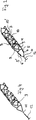
Die erfindungsgemäße Vorrichtung ist im Prinzip eine flächige Struktur, die zu einem rohrförmigen Gebilde gerollt ist und einen Schlitz aufweist, der sich wendel- oder helixförmig über die Mantelfläche der Stentstruktur erstreckt. Dieser Schlitz kann dabei eine vollständige Wendel von 360° darstellen, aber auch eine nur partielle von beispielsweise etwa 180° oder 120°. Die Mantelfläche der Stentstruktur klafft im Bereich dieses Schlitzes auf, wobei die Breite des Schlitzes am Einsatzort jeweils auch vom Lumen des Gefäßes bestimmt wird, da sich die Stentstruktur nach der Freisetzung aus dem Katheter nur so weit entfalten kann, wie es das Gefäßlumen zulässt.The device according to the invention is, in principle, a planar structure, which is rolled into a tubular structure and has a slot which extends helically or helically over the lateral surface of the stent structure. This slot can represent a complete helix of 360 °, but also only a partial of, for example, about 180 ° or 120 °. The lateral surface of the stent structure gapes in the region of this slot, wherein the width of the slot at the site is also determined by the lumen of the vessel, since the stent structure after release from the catheter can develop only as far as the vessel lumen allows.
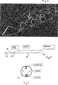
Um die Stentstruktur zum einen räumlich zu fixieren und andererseits mit einer gewissen Spannung zu versehen, erstreckt sich am proximalen Ende der Stentstruktur ein Spannbügel über den Schlitz. Der Spannbügel erhöht die Radialkraft der selbstexpandierenden Struktur, dient aber auch dazu, die einander gegenüberliegenden Kanten der Stentstruktur entlang des Schlitzes in ihrer Position zueinander festzuhalten.In order to fix the stent structure on the one hand spatially and on the other hand to provide a certain tension, extends at the proximal end of the stent structure, a clamping bracket on the slot. The stirrup increases the radial force of the self-expanding structure, but also serves to hold the opposite edges of the stent structure along the slot in their position to each other.
Die erfindungsgemäße Thrombektomievorrichtung kann über dem proximalen Spannbügel hinaus weitere Spannbügel im zentralen und distalen Bereich aufweisen. Bei Verwendung von Formgedächtnismaterialien mit hinreichender Vorspannung kann aber auch auf jeglichen Spannbügel verzichtet werden.The thrombectomy device according to the invention can have further tensioning straps in the central and distal region beyond the proximal tensioning bow. When using shape memory materials with sufficient preload but can be dispensed with any clamping bracket.
Die erfindungsgemäße Thrombektomievorrichtung wird so eingesetzt, dass sie mittels eines Katheters an den Einsatzort verbracht wird und dort entweder im Thrombus selbst oder distal vom Thrombus freigesetzt wird. Die Vorrichtung expandiert im Gefäß und passt sich an das Gefäßlumen an. Entweder schon beim Aufspannen oder beim Zurückziehen verfängt sich das Thrombusmaterial in der Maschenstruktur und wird beim Zurückziehen der Vorrichtung in den Katheter mitgenommen. An der Gefäßwand anhaftende Teile des Thrombus werden durch die Scherwirkung der Maschen und der Kanten entlang des Schlitzes mitgenommen. Der Thrombus wird in den Katheter eingezogen und mit dem Katheter aus dem Körper entfernt.The thrombectomy device according to the invention is used so that it is brought to the site by means of a catheter and released there either in the thrombus itself or distally from the thrombus. The device expands in the vessel and conforms to the vessel lumen. Either already during clamping or retraction, the thrombus material gets caught in the mesh structure and is dragged into the catheter when the device is withdrawn. Parts of the thrombus adhering to the vessel wall are taken along by the shearing action of the meshes and the edges along the slot. The thrombus is drawn into the catheter and removed with the catheter from the body.
Bei der Extraktion des Thrombus hat der wendelförmige Verlauf des Schlitzes über die Mantelfläche den besonderen Vorteil, dass die Kanten der Stentstruktur entlang des Schlitzes bei Zug tangential entlang des Umfanges der Gefäßwandung wandern. Dies verbessert die Scherwirkung. Gleichzeitig verbessert (vermindert) sich durch den wendelförmigen Verlauf die Biegesteifigkeit dergestalt, dass eine bessere Anpassung an kurvige Gefäße möglich ist. Dies erleichtert sowohl die Platzierung als auch die Extraktion von Thromben aus komplexen Gefäßstrukturen.During the extraction of the thrombus, the helical course of the slot over the lateral surface has the particular advantage that the edges of the stent structure move along the slot tangentially along the circumference of the vessel wall along the slot. This improves the shear effect. At the same time, the spiral stiffness improves (reduces) the bending stiffness in such a way that better adaptation to curvy vessels is possible. This facilitates both the placement and the extraction of thrombi from complex vascular structures.
Der proximale Bügel verbessert den Radialkraftverlauf der Stentstruktur im proximalen Bereich. Insbesondere vermindert der Bügel eine Verschlankung der Stentstruktur und der Zugbelastung, wie sie beim Einziehen in den Katheter auftritt. Gleichzeitig wird eine zusätzliche Schälwirkung erreicht, wie sie auch von den Maschen und Kanten der Stentstruktur ausgeübt wird.The proximal stirrup improves the radial force curve of the stent structure in the proximal region. In particular, the stirrup reduces the slimming of the stent structure and the tensile load that occurs when it is drawn into the catheter. At the same time an additional peeling effect is achieved, as it is also exerted by the mesh and edges of the stent structure.
Von Bedeutung ist aber insbesondere die Verbesserung der Aufspannkraft im proximalen Bereich, die eine optimale Anpassung der Stentstruktur an das Gefäßlumen ermöglicht. Gleichzeitig werden die vom Schlitz voneinander getrennten Bereiche des Stents daran gehindert, sich gegeneinander zu verschieben.Of particular importance, however, is the improvement of the clamping force in the proximal region, which allows optimal adaptation of the stent structure to the vessel lumen. At the same time, the portions of the stent which are separated from each other by the slot are prevented from shifting relative to one another.
Um ein problemloses Einziehen der Stentstruktur mit dem Bügel in den Katheter zu ermöglichen, weist der Spannbügel zum distalen Ende der Stentstruktur hin. Dies bedeutet, dass der Bogen des Bügels nach distal geschlossen ist, dagegen nach proximal zusammen mit den Verbindern eine Schlaufe bildet, die im Kopplungselement zusammenläuft, ähnlich der Öffnung eines Fangkorbs. To allow easy insertion of the stent structure with the bracket in the catheter, the clamping bracket points to the distal end of the stent structure. This means that the bow of the stirrup is closed distally, but forms proximally along with the connectors a loop that converges in the coupling element, similar to the opening of a collecting basket.
Gemäß einer Variante kann die erfindungsgemäße Stentstruktur am distalen Ende durch eine Maschenstruktur verschlossen sein, so dass sich thrombotisches Material darin wie in einem Fangkorb sammeltAccording to a variant, the stent structure according to the invention may be closed at the distal end by a mesh structure, so that thrombotic material collects therein as in a collecting basket
Wie schon festgestellt, wird die erfindungsgemäße Stentstruktur vorzugsweise aus einem zylindrischen Rohr mit Hilfe eines Lasers geschnitten. Dies erlaubt es, den einzelnen Maschen einen besonderen Querschnitt zu verleihen, beispielsweise quadratisch, rechteckig oder trapezförmig. Bei den rechteckigen und trapezförmigen Ausführungsformen kann zum einen die schmale Seite des Querschnitts an der Außenfläche liegen, zum anderen die lange Seite. Bevorzugt ist es, dass die schmale Seite sowohl des Rechtecks wie insbesondere des Trapezes zur Gefäßwand weist, was ein leichteres Eindringen des Thrombus in die Maschenstruktur ermöglicht und die gute Verdrängung des Thrombusmasse bei der Expansion der Stentstruktur erlaubt.As already stated, the stent structure according to the invention is preferably cut from a cylindrical tube by means of a laser. This makes it possible to give the individual meshes a special cross section, for example square, rectangular or trapezoidal. In the case of the rectangular and trapezoidal embodiments, on the one hand, the narrow side of the cross section may lie on the outer surface, on the other hand the long side. It is preferred that the narrow side of both the rectangle and in particular the trapezoid facing the vessel wall, which allows for easier penetration of the thrombus in the mesh structure and allows the good displacement of the thrombus mass in the expansion of the stent structure.
Die am proximalen Ende der Stentstruktur angeordneten Verbinder führen von an den Schlitz angrenzenden proximalen Waben zu einem Kopplungselement, in dem sie zusammengeführt sind. Sie sind Teile der Stentstruktur und bestehen deshalb aus dem gleichen Material.The connectors arranged at the proximal end of the stent structure lead from proximal honeycombs adjacent to the slot to a coupling element in which they are brought together. They are parts of the stent structure and are therefore made of the same material.
Der Führungsdraht der erfindungsgemäßen Thrombektomievorrichtung ist ein üblicher Führungsdraht, wie er für endovaskuläre und insbesondere neuroradiologische Zwecke eingesetzt wird. Er endet distal in dem Kopplungselement, das seinerseits die proximalen Enden der Verbinder aufnimmt.The guidewire of the thrombectomy device of the present invention is a common guidewire used for endovascular and, in particular, neuroradiological purposes. It terminates distally in the coupling element, which in turn receives the proximal ends of the connectors.
Das Kopplungselement selbst kann ein einfacher Schweißpunkt sein, in dem Führungsdraht und Verbinder zusammengeführt sind. Es kann weiterhin aber auch ein übliches Kopplungselement sein, das die Freisetzung der zylindrischen Stentstruktur erlaubt, die insbesondere dann geboten ist, wenn eine Rückholung aus medizinischen Gründen nicht angezeigt ist, beispielsweise weil sie zu Schäden beim Patienten führen würde. In diesem Fall kann die Stentstruktur als Stent im Körper verbleiben und ihre Wirkung dadurch entfalten, dass sie im Thrombus einen Kanal ausbildet; der Thrombus wird durch die Maschenstruktur an die Gefäßwand gepresst.The coupling element itself may be a simple welding point in which guidewire and connector are brought together. However, it may also be a common coupling element, which allows the release of the cylindrical stent structure, which is particularly appropriate when a retrieval for medical reasons is not indicated, for example because it would lead to damage to the patient. In this case, the stent structure can remain as a stent in the body and develop its effect by forming a channel in the thrombus; The thrombus is pressed through the mesh structure to the vessel wall.
Für letzteren Fall ist das Kopplungselement beispielsweise ein mechanisches Kopplungselement, das geeignet ist, bei Austritt aus dem Katheter die Verbinder freizusetzen. Zahlreiche solcher Systeme sind in der Fachliteratur beschrieben. Ebenfalls beschrieben sind hydraulische Ablösesysteme. Besonders geeignet sind elektrolytische Ablösungssysteme, bei denen ein elektrolytisch korrodierbares Teil durch Stromeinwirkung aufgelöst wird und die Verbindung zwischen Stentstruktur und Führungsdraht durchtrennt. Gemäß einer ersten Variante kann das Kopplungselement als solch ein elektrolytisch auflösbares Teil gestaltet sein, gemäß einer zweiten Variante sind die Verbinder mit einer solchen Ablösestelle bzw. einem separaten Ablöseelement versehen, das sich bei Stromeinwirkung auflöst. Geeignet als Ablöseelemente sind vorkorrodierte Edelstahlelemente, Magnesiumelemente oder Kobalt-Chrom-Legierungen. Solche Systeme sind in der Literatur beschrieben.For the latter case, the coupling element is, for example, a mechanical coupling element which is suitable for releasing the connectors on exiting from the catheter. Numerous such systems are described in the specialist literature. Also described are hydraulic release systems. Particularly suitable are electrolytic detachment systems in which an electrolytically corrodible part is dissolved by the action of current and cuts through the connection between the stent structure and the guide wire. According to a first variant, the coupling element may be designed as such an electrolytically resolvable part, according to a second variant, the connectors are provided with such a detachment point or a separate release element which dissolves when current is applied. Suitable as release elements are pre-corroded stainless steel elements, magnesium elements or cobalt-chromium alloys. Such systems are described in the literature.
Bei der Gestaltung des proximalen Bereichs der zylindrischen Stentstruktur ist eine kurze Ausführung der Verbinder bevorzugt. Der Weg zwischen proximalem Ende der Maschenstruktur und Kopplungselement soll kurz gehalten werden. Dies verkürzt zum einen die ungenutzte Länge der Vorrichtung und erhöht andererseits die Spannung in der mit dem Spannbügel gebildeten Fangschlinge am proximalen Ende der Struktur.In the design of the proximal portion of the cylindrical stent structure, a short design of the connectors is preferred. The path between the proximal end of the mesh structure and the coupling element should be kept short. On the one hand, this shortens the unused length of the device and, on the other hand, increases the tension in the catch loop formed by the tension bow at the proximal end of the structure.
Gemäß einer besonderen Ausführungsform kann der distale Bereich der zylindrischen Stentstruktur kegelförmig oder trompetenförmig aufgeweitet sein, um in diesem Bereich eine gute Anpassung an das Gefäßlumen zu ermöglichen. Bei der Extraktion von Thromben aus einem Gefäß kommt es auf einen möglichst großen Wirkbereich an, d. h. auf den Kontakt der Mantelfläche mit der Gefäßwand. Je größer die Kontaktfläche, desto größer die Chance, den Thrombus vollständig zu entfernen.According to a particular embodiment, the distal region of the cylindrical stent structure may be widened conically or trumpet-shaped in order to allow a good adaptation to the vessel lumen in this region. In the extraction of thrombi from a vessel, the largest possible range of action is important, i. H. on the contact of the lateral surface with the vessel wall. The larger the contact area, the greater the chance of completely removing the thrombus.
Führungsdraht und/oder Stentstruktur können in üblicher Weise mit Markern versehen sein, die röntgendicht sind, beispielsweise in Form von Spiralen oder Manschetten.Guidewire and / or stent structure may be conventionally provided with markers which are radiopaque, for example in the form of spirals or cuffs.
Die Erfindung wird durch die beiliegenden Abbildungen näher erläutert. Es zeigen:The invention is explained in more detail by the accompanying drawings. Show it:
In der flächigen Darstellung der
Die Darstellung in
Die Varianten von
Beiden Ausführungsformen ist gemein, dass der Schlitz
In den Darstellungen von
Deutlich zu erkennen in
In den Abbildungen stellen gleiche Bezugszeichen gleiche Sachverhalte dar. In the figures, like reference numerals represent like facts.
ZITATE ENTHALTEN IN DER BESCHREIBUNG QUOTES INCLUDE IN THE DESCRIPTION
Diese Liste der vom Anmelder aufgeführten Dokumente wurde automatisiert erzeugt und ist ausschließlich zur besseren Information des Lesers aufgenommen. Die Liste ist nicht Bestandteil der deutschen Patent- bzw. Gebrauchsmusteranmeldung. Das DPMA übernimmt keinerlei Haftung für etwaige Fehler oder Auslassungen.This list of the documents listed by the applicant has been generated automatically and is included solely for the better information of the reader. The list is not part of the German patent or utility model application. The DPMA assumes no liability for any errors or omissions.
Zitierte PatentliteraturCited patent literature
- US 6245089 B1 [0005] US 6245089 B1 [0005]
- US 5171233 A1 [0005] US 5171233 A1 [0005]
- WO 2004/008991 A1 [0007] WO 2004/008991 A1 [0007]
Zitierte Nicht-PatentliteraturCited non-patent literature
- Thomas E. Meier et al., Stroke 2002 (9) 2232 [0005] Thomas E. Meier et al., Stroke 2002 (9) 2232 [0005]
Claims (13)
Priority Applications (12)
| Application Number | Priority Date | Filing Date | Title |
|---|---|---|---|
| DE102010051740A DE102010051740A1 (en) | 2010-11-19 | 2010-11-19 | thrombectomy |
| KR1020137015048A KR101827593B1 (en) | 2010-11-19 | 2011-11-18 | Thrombectomy Device |
| SG2013038518A SG190336A1 (en) | 2010-11-19 | 2011-11-18 | Thrombectomy device |
| AU2011331519A AU2011331519B2 (en) | 2010-11-19 | 2011-11-18 | Thrombectomy device |
| JP2013539166A JP6043294B2 (en) | 2010-11-19 | 2011-11-18 | Thrombectomy device |
| EP11791436.6A EP2640285B1 (en) | 2010-11-19 | 2011-11-18 | Thrombectomy device |
| PCT/EP2011/005817 WO2012065748A1 (en) | 2010-11-19 | 2011-11-18 | Thrombectomy device |
| CA2818262A CA2818262C (en) | 2010-11-19 | 2011-11-18 | Thrombectomy device |
| BR112013012388-5A BR112013012388B1 (en) | 2010-11-19 | 2011-11-18 | THROMBECTOMY DEVICE |
| CN201180064691.6A CN103313668B (en) | 2010-11-19 | 2011-11-18 | Thrombectomy device |
| US13/885,514 US9737318B2 (en) | 2010-11-19 | 2011-11-18 | Thrombectomy device |
| ES11791436.6T ES2638281T3 (en) | 2010-11-19 | 2011-11-18 | Thrombectomy device |
Applications Claiming Priority (1)
| Application Number | Priority Date | Filing Date | Title |
|---|---|---|---|
| DE102010051740A DE102010051740A1 (en) | 2010-11-19 | 2010-11-19 | thrombectomy |
Publications (1)
| Publication Number | Publication Date |
|---|---|
| DE102010051740A1 true DE102010051740A1 (en) | 2012-05-24 |
Family
ID=45099009
Family Applications (1)
| Application Number | Title | Priority Date | Filing Date |
|---|---|---|---|
| DE102010051740A Withdrawn DE102010051740A1 (en) | 2010-11-19 | 2010-11-19 | thrombectomy |
Country Status (12)
| Country | Link |
|---|---|
| US (1) | US9737318B2 (en) |
| EP (1) | EP2640285B1 (en) |
| JP (1) | JP6043294B2 (en) |
| KR (1) | KR101827593B1 (en) |
| CN (1) | CN103313668B (en) |
| AU (1) | AU2011331519B2 (en) |
| BR (1) | BR112013012388B1 (en) |
| CA (1) | CA2818262C (en) |
| DE (1) | DE102010051740A1 (en) |
| ES (1) | ES2638281T3 (en) |
| SG (1) | SG190336A1 (en) |
| WO (1) | WO2012065748A1 (en) |
Cited By (1)
| Publication number | Priority date | Publication date | Assignee | Title |
|---|---|---|---|---|
| DE102017111486A1 (en) * | 2017-05-17 | 2018-11-22 | Phenox Gmbh | Coating for medical devices |
Families Citing this family (76)
| Publication number | Priority date | Publication date | Assignee | Title |
|---|---|---|---|---|
| DE10233085B4 (en) | 2002-07-19 | 2014-02-20 | Dendron Gmbh | Stent with guide wire |
| WO2005094283A2 (en) | 2004-03-25 | 2005-10-13 | Hauser David L | Vascular filter device |
| WO2007092820A2 (en) | 2006-02-03 | 2007-08-16 | Lazarus Effect, Inc. | Methods and devices for restoring blood flow within blocked vasculature |
| US11202646B2 (en) | 2007-04-17 | 2021-12-21 | Covidien Lp | Articulating retrieval devices |
| US10076346B2 (en) | 2007-04-17 | 2018-09-18 | Covidien Lp | Complex wire formed devices |
| US11337714B2 (en) | 2007-10-17 | 2022-05-24 | Covidien Lp | Restoring blood flow and clot removal during acute ischemic stroke |
| US10123803B2 (en) | 2007-10-17 | 2018-11-13 | Covidien Lp | Methods of managing neurovascular obstructions |
| CN102036611B (en) | 2007-12-26 | 2015-01-28 | 拉撒路效应公司 | Retrieval systems and methods for use thereof |
| RU2506912C2 (en) | 2008-02-22 | 2014-02-20 | Микро Терапьютикс, Инк. | Methods and device for restoring flow |
| DE202008009604U1 (en) | 2008-07-17 | 2008-11-27 | Sahl, Harald, Dr. | Membrane implant for the treatment of cerebral artery aneurysms |
| WO2011106426A1 (en) | 2010-02-23 | 2011-09-01 | Maria Aboytes | Devices and methods for vascular recanalization |
| WO2012009675A2 (en) | 2010-07-15 | 2012-01-19 | Lazarus Effect, Inc. | Retrieval systems and methods for use thereof |
| DE102011011869A1 (en) | 2011-02-22 | 2012-08-23 | Phenox Gmbh | implant |
| DE102011012501A1 (en) | 2011-02-25 | 2012-08-30 | Phenox Gmbh | Implant with fiber fleece |
| DE102011101522A1 (en) | 2011-05-13 | 2012-11-15 | Phenox Gmbh | thrombectomy |
| EP3741314B1 (en) | 2011-05-23 | 2022-12-21 | Covidien LP | Retrieval systems |
| US9072624B2 (en) | 2012-02-23 | 2015-07-07 | Covidien Lp | Luminal stenting |
| WO2014047650A1 (en) | 2012-09-24 | 2014-03-27 | Inceptus Medical LLC | Device and method for treating vascular occlusion |
| US9314248B2 (en) | 2012-11-06 | 2016-04-19 | Covidien Lp | Multi-pivot thrombectomy device |
| US8784434B2 (en) | 2012-11-20 | 2014-07-22 | Inceptus Medical, Inc. | Methods and apparatus for treating embolism |
| EP3202340A1 (en) | 2013-03-15 | 2017-08-09 | National University of Ireland Galway | A device suitable for removing matter from inside the lumen and the wall of a body lumen |
| CN103284775B (en) * | 2013-06-04 | 2015-06-10 | 加奇生物科技(上海)有限公司 | Encephalic thrombosis removing device |
| US20150018860A1 (en) | 2013-07-12 | 2015-01-15 | Inceptus Medical, Llc | Methods and apparatus for treating small vessel thromboembolisms |
| US10076399B2 (en) | 2013-09-13 | 2018-09-18 | Covidien Lp | Endovascular device engagement |
| US9592139B2 (en) | 2013-10-04 | 2017-03-14 | Covidien Lp | Stents twisted prior to deployment and untwisted during deployment |
| US10238406B2 (en) | 2013-10-21 | 2019-03-26 | Inari Medical, Inc. | Methods and apparatus for treating embolism |
| US9795400B2 (en) | 2013-11-13 | 2017-10-24 | Covidien Lp | Galvanically assisted attachment of medical devices to thrombus |
| CN106470728A (en) | 2014-06-09 | 2017-03-01 | 因赛普特斯医学有限责任公司 | For treating retraction and aspirator and related system and the method for thromboembolism |
| KR101530828B1 (en) | 2014-09-23 | 2015-06-24 | 윤성원 | endovascular device for thrombus removal and flow restoration |
| DE102014222600A1 (en) * | 2014-11-05 | 2016-05-12 | Epflex Feinwerktechnik Gmbh | Medical safety wire instrument |
| EP3017775A1 (en) | 2014-11-07 | 2016-05-11 | National University of Ireland, Galway | A thrombectomy device |
| CN104434353A (en) * | 2014-12-04 | 2015-03-25 | 曾延华 | Electronic detaching and etching covered stent for treatment of intracranial aneurysm and operation method thereof |
| US10456560B2 (en) | 2015-02-11 | 2019-10-29 | Covidien Lp | Expandable tip medical devices and methods |
| WO2016197036A1 (en) | 2015-06-03 | 2016-12-08 | Brian Martin | Flexible intravascular treatment devices and associated systems and methods of use |
| EP3542737B1 (en) | 2015-09-25 | 2021-06-16 | Covidien LP | Medical device delivery system |
| US10537344B2 (en) | 2015-10-23 | 2020-01-21 | Covidien Lp | Rotatable connection between an intervention member and a manipulation member of an endovascular device |
| EP3364891B1 (en) | 2015-10-23 | 2023-08-09 | Inari Medical, Inc. | Device for intravascular treatment of vascular occlusion |
| US9700332B2 (en) | 2015-10-23 | 2017-07-11 | Inari Medical, Inc. | Intravascular treatment of vascular occlusion and associated devices, systems, and methods |
| US10342571B2 (en) | 2015-10-23 | 2019-07-09 | Inari Medical, Inc. | Intravascular treatment of vascular occlusion and associated devices, systems, and methods |
| US10874410B2 (en) | 2015-11-04 | 2020-12-29 | Covidien Lp | Clot removal by adhesion |
| CN115300748A (en) | 2015-12-18 | 2022-11-08 | 伊纳里医疗有限公司 | Catheter shafts and related devices, systems, and methods |
| CN105455878A (en) * | 2016-01-26 | 2016-04-06 | 加奇生物科技(上海)有限公司苏州分公司 | Catching device |
| US10052185B2 (en) | 2016-02-12 | 2018-08-21 | Covidien Lp | Vascular device marker attachment |
| US10265089B2 (en) | 2016-02-12 | 2019-04-23 | Covidien Lp | Vascular device visibility |
| EP3222390A1 (en) | 2016-03-23 | 2017-09-27 | HILTI Aktiengesellschaft | Chisel |
| CN110312481B (en) | 2016-10-24 | 2023-04-11 | 伊纳里医疗有限公司 | Devices and methods for treating vascular occlusions |
| US11191555B2 (en) | 2017-05-12 | 2021-12-07 | Covidien Lp | Retrieval of material from vessel lumens |
| US11129630B2 (en) | 2017-05-12 | 2021-09-28 | Covidien Lp | Retrieval of material from vessel lumens |
| US11298145B2 (en) | 2017-05-12 | 2022-04-12 | Covidien Lp | Retrieval of material from vessel lumens |
| US10722257B2 (en) | 2017-05-12 | 2020-07-28 | Covidien Lp | Retrieval of material from vessel lumens |
| US10709464B2 (en) | 2017-05-12 | 2020-07-14 | Covidien Lp | Retrieval of material from vessel lumens |
| EP3634211A4 (en) | 2017-06-07 | 2021-03-17 | Covidien LP | Systems and methods for detecting strokes |
| CN110831523B (en) | 2017-06-12 | 2022-09-13 | 柯惠有限合伙公司 | Tool for sheathing a treatment device, and associated systems and methods |
| US10478322B2 (en) | 2017-06-19 | 2019-11-19 | Covidien Lp | Retractor device for transforming a retrieval device from a deployed position to a delivery position |
| US10575864B2 (en) | 2017-06-22 | 2020-03-03 | Covidien Lp | Securing element for resheathing an intravascular device and associated systems and methods |
| US10342686B2 (en) | 2017-08-10 | 2019-07-09 | Covidien Lp | Thin film mesh hybrid for treating vascular defects |
| EP3678731A4 (en) | 2017-09-06 | 2021-06-09 | Inari Medical, Inc. | Hemostasis valves and methods of use |
| US10258357B1 (en) | 2017-10-16 | 2019-04-16 | Michael Bruce Horowitz | Catheter based retrieval device with proximal body having axial freedom of movement |
| US20220104839A1 (en) | 2017-10-16 | 2022-04-07 | Retriever Medical, Inc. | Clot Removal Methods and Devices with Multiple Independently Controllable Elements |
| AU2021362245A1 (en) | 2017-10-16 | 2023-05-25 | Retriever Medical, Inc. | Clot removal methods and devices with multiple independently controllable elements |
| US10835398B2 (en) | 2017-11-03 | 2020-11-17 | Covidien Lp | Meshes and devices for treating vascular defects |
| US10709463B2 (en) | 2017-12-11 | 2020-07-14 | Covidien Lp | Electrically enhanced retrieval of material from vessel lumens |
| US11058444B2 (en) | 2017-12-11 | 2021-07-13 | Covidien Lp | Electrically enhanced retrieval of material from vessel lumens |
| US11154314B2 (en) | 2018-01-26 | 2021-10-26 | Inari Medical, Inc. | Single insertion delivery system for treating embolism and associated systems and methods |
| CN108433781B (en) * | 2018-03-30 | 2023-03-21 | 刘振生 | Intracranial blood vessel clamping type thrombus taking device |
| US11090071B2 (en) | 2018-06-22 | 2021-08-17 | Covidien Lp | Electrically enhanced retrieval of material from vessel lumens |
| JP2021534851A (en) | 2018-08-13 | 2021-12-16 | イナリ メディカル, インコーポレイテッド | Systems and related devices and methods for treating embolism |
| KR102125615B1 (en) | 2018-08-28 | 2020-06-22 | 인제대학교 산학협력단 | Surgical instrument for stent |
| US11612430B2 (en) | 2019-03-19 | 2023-03-28 | Covidien Lp | Electrically enhanced retrieval of material from vessel lumens |
| US11191558B2 (en) | 2019-06-12 | 2021-12-07 | Covidien Lp | Retrieval of material from corporeal lumens |
| US11523838B2 (en) | 2019-06-12 | 2022-12-13 | Covidien Lp | Retrieval of material from corporeal lumens |
| US11864779B2 (en) | 2019-10-16 | 2024-01-09 | Inari Medical, Inc. | Systems, devices, and methods for treating vascular occlusions |
| US11395668B2 (en) | 2019-12-12 | 2022-07-26 | Covidien Lp | Electrically enhanced retrieval of material from vessel lumens |
| CN112998798A (en) * | 2021-02-10 | 2021-06-22 | 心凯诺医疗科技(上海)有限公司 | Novel intracranial stent system |
| US11944374B2 (en) | 2021-08-30 | 2024-04-02 | Covidien Lp | Electrical signals for retrieval of material from vessel lumens |
| WO2023237090A1 (en) * | 2022-06-10 | 2023-12-14 | Accumedical Beijing Ltd. | Neurovascular stent |
Citations (3)
| Publication number | Priority date | Publication date | Assignee | Title |
|---|---|---|---|---|
| US5171233A (en) | 1990-04-25 | 1992-12-15 | Microvena Corporation | Snare-type probe |
| US6245089B1 (en) | 1997-03-06 | 2001-06-12 | Scimed Life Systems, Inc. | Distal protection device and method |
| WO2004008991A1 (en) | 2002-07-19 | 2004-01-29 | Dendron Gmbh | Medical implant |
Family Cites Families (22)
| Publication number | Priority date | Publication date | Assignee | Title |
|---|---|---|---|---|
| US5441515A (en) * | 1993-04-23 | 1995-08-15 | Advanced Cardiovascular Systems, Inc. | Ratcheting stent |
| US5449373A (en) * | 1994-03-17 | 1995-09-12 | Medinol Ltd. | Articulated stent |
| US5904698A (en) * | 1997-06-10 | 1999-05-18 | Applied Medical Resources Corporation | Surgical shaving device for use within body conduits |
| US8080026B2 (en) * | 2003-01-21 | 2011-12-20 | Angioscore, Inc. | Apparatus and methods for treating hardened vascular lesions |
| US20050246008A1 (en) * | 2004-04-30 | 2005-11-03 | Novostent Corporation | Delivery system for vascular prostheses and methods of use |
| DE102004040868A1 (en) | 2004-08-23 | 2006-03-09 | Miloslavski, Elina | Device for removing thrombi |
| DE102005059670A1 (en) | 2005-12-12 | 2007-06-14 | Phenox Gmbh | Device for removing thrombi from blood vessels |
| WO2007089897A2 (en) * | 2006-02-01 | 2007-08-09 | The Cleveland Clinic Foundation | Inflatable-deflatable passive exercise unit |
| DE102006044831A1 (en) | 2006-09-20 | 2008-04-03 | Phenox Gmbh | Device for removing thrombi from blood vessels |
| DE102007012964A1 (en) | 2007-03-06 | 2008-09-11 | Phenox Gmbh | Implant for influencing blood flow |
| RU2506912C2 (en) * | 2008-02-22 | 2014-02-20 | Микро Терапьютикс, Инк. | Methods and device for restoring flow |
| DE202008009604U1 (en) | 2008-07-17 | 2008-11-27 | Sahl, Harald, Dr. | Membrane implant for the treatment of cerebral artery aneurysms |
| DE102008038195A1 (en) | 2008-08-19 | 2010-02-25 | Phenox Gmbh | Device for opening occluded blood vessels |
| DE102008050085A1 (en) | 2008-10-06 | 2010-04-08 | Phenox Gmbh | implant replacement |
| US8795345B2 (en) * | 2009-07-08 | 2014-08-05 | Concentric Medical, Inc. | Vascular and bodily duct treatment devices and methods |
| US8795317B2 (en) * | 2009-07-08 | 2014-08-05 | Concentric Medical, Inc. | Embolic obstruction retrieval devices and methods |
| US8328863B2 (en) * | 2010-04-22 | 2012-12-11 | Abbott Cardiovascular Systems Inc. | Optimal ratio of polar and bending moment of inertia for stent strut design |
| DE102010021947A1 (en) | 2010-05-28 | 2011-12-01 | Phenox Gmbh | implant replacement |
| DE102010044746A1 (en) | 2010-09-08 | 2012-03-08 | Phenox Gmbh | Implant for influencing the blood flow in arteriovenous malformations |
| DE102011011869A1 (en) | 2011-02-22 | 2012-08-23 | Phenox Gmbh | implant |
| DE102011012501A1 (en) | 2011-02-25 | 2012-08-30 | Phenox Gmbh | Implant with fiber fleece |
| DE102011101522A1 (en) | 2011-05-13 | 2012-11-15 | Phenox Gmbh | thrombectomy |
-
2010
- 2010-11-19 DE DE102010051740A patent/DE102010051740A1/en not_active Withdrawn
-
2011
- 2011-11-18 ES ES11791436.6T patent/ES2638281T3/en active Active
- 2011-11-18 US US13/885,514 patent/US9737318B2/en active Active
- 2011-11-18 EP EP11791436.6A patent/EP2640285B1/en active Active
- 2011-11-18 CA CA2818262A patent/CA2818262C/en active Active
- 2011-11-18 CN CN201180064691.6A patent/CN103313668B/en active Active
- 2011-11-18 AU AU2011331519A patent/AU2011331519B2/en active Active
- 2011-11-18 BR BR112013012388-5A patent/BR112013012388B1/en active IP Right Grant
- 2011-11-18 WO PCT/EP2011/005817 patent/WO2012065748A1/en active Application Filing
- 2011-11-18 KR KR1020137015048A patent/KR101827593B1/en active IP Right Grant
- 2011-11-18 SG SG2013038518A patent/SG190336A1/en unknown
- 2011-11-18 JP JP2013539166A patent/JP6043294B2/en active Active
Patent Citations (3)
| Publication number | Priority date | Publication date | Assignee | Title |
|---|---|---|---|---|
| US5171233A (en) | 1990-04-25 | 1992-12-15 | Microvena Corporation | Snare-type probe |
| US6245089B1 (en) | 1997-03-06 | 2001-06-12 | Scimed Life Systems, Inc. | Distal protection device and method |
| WO2004008991A1 (en) | 2002-07-19 | 2004-01-29 | Dendron Gmbh | Medical implant |
Non-Patent Citations (1)
| Title |
|---|
| Thomas E. Meier et al., Stroke 2002 (9) 2232 |
Cited By (1)
| Publication number | Priority date | Publication date | Assignee | Title |
|---|---|---|---|---|
| DE102017111486A1 (en) * | 2017-05-17 | 2018-11-22 | Phenox Gmbh | Coating for medical devices |
Also Published As
| Publication number | Publication date |
|---|---|
| CA2818262C (en) | 2018-03-20 |
| US20130296916A1 (en) | 2013-11-07 |
| KR20140008315A (en) | 2014-01-21 |
| JP2014500763A (en) | 2014-01-16 |
| EP2640285A1 (en) | 2013-09-25 |
| AU2011331519B2 (en) | 2016-02-25 |
| WO2012065748A1 (en) | 2012-05-24 |
| BR112013012388B1 (en) | 2020-05-26 |
| KR101827593B1 (en) | 2018-02-08 |
| SG190336A1 (en) | 2013-06-28 |
| CA2818262A1 (en) | 2012-05-24 |
| BR112013012388A2 (en) | 2016-08-30 |
| EP2640285B1 (en) | 2017-05-24 |
| JP6043294B2 (en) | 2016-12-14 |
| CN103313668B (en) | 2016-03-16 |
| CN103313668A (en) | 2013-09-18 |
| US9737318B2 (en) | 2017-08-22 |
| ES2638281T3 (en) | 2017-10-19 |
| AU2011331519A1 (en) | 2013-06-13 |
Similar Documents
| Publication | Publication Date | Title |
|---|---|---|
| EP2640285B1 (en) | Thrombectomy device | |
| EP2706929B9 (en) | Thrombectomy device | |
| EP1962702B1 (en) | Device for the removal of thrombi from blood vessels | |
| EP2404561B1 (en) | Device for removing blood clots | |
| EP1722695B1 (en) | Device for rechannelling a cavity, organ path or vessel | |
| EP1948042B1 (en) | Device for eliminating thromboses | |
| EP2344052B1 (en) | Device for reopening occluded blood vessels | |
| DE69529338T3 (en) | Intravascular filter device | |
| EP3764928B1 (en) | Thrombectomy device | |
| DE102006044831A1 (en) | Device for removing thrombi from blood vessels | |
| EP1542617A1 (en) | Medical implant | |
| DE102009009003A1 (en) | implant | |
| DE102005053434A1 (en) | Thromboses removal device e.g. for removal of foreign bodies and thromboses from body cavities and blood vessels, has guide wire with far element which is provided with orthogonal structure which is made from fiber bristles | |
| DE102018105679A1 (en) | Temporary occlusion of aneurysmal necks | |
| DE102021100703A1 (en) | thrombectomy device | |
| DE102017130564A1 (en) | Implant for aneurysms | |
| DE102022114767A1 (en) | Endovascular device with guide wire |
Legal Events
| Date | Code | Title | Description |
|---|---|---|---|
| R123 | Application deemed withdrawn due to non-payment of filing fee | ||
| R409 | Internal rectification of the legal status completed | ||
| R409 | Internal rectification of the legal status completed | ||
| R012 | Request for examination validly filed | ||
| R119 | Application deemed withdrawn, or ip right lapsed, due to non-payment of renewal fee |