EP3637882A1 - Procédé de commande de puissance de transmission dans un système de communication sans fil et appareil associé - Google Patents
Procédé de commande de puissance de transmission dans un système de communication sans fil et appareil associé Download PDFInfo
- Publication number
- EP3637882A1 EP3637882A1 EP18799025.4A EP18799025A EP3637882A1 EP 3637882 A1 EP3637882 A1 EP 3637882A1 EP 18799025 A EP18799025 A EP 18799025A EP 3637882 A1 EP3637882 A1 EP 3637882A1
- Authority
- EP
- European Patent Office
- Prior art keywords
- stti
- tti
- sps
- terminal
- transmission power
- Prior art date
- Legal status (The legal status is an assumption and is not a legal conclusion. Google has not performed a legal analysis and makes no representation as to the accuracy of the status listed.)
- Granted
Links
- 238000000034 method Methods 0.000 title claims abstract description 41
- 238000004891 communication Methods 0.000 title claims abstract description 39
- 230000005540 biological transmission Effects 0.000 claims abstract description 113
- 238000009825 accumulation Methods 0.000 claims description 27
- 230000001105 regulatory effect Effects 0.000 description 19
- 230000011664 signaling Effects 0.000 description 18
- 230000004044 response Effects 0.000 description 13
- 238000012545 processing Methods 0.000 description 12
- 125000004122 cyclic group Chemical group 0.000 description 10
- 238000013468 resource allocation Methods 0.000 description 9
- 230000006870 function Effects 0.000 description 8
- 230000008569 process Effects 0.000 description 7
- 101150071746 Pbsn gene Proteins 0.000 description 6
- 230000002776 aggregation Effects 0.000 description 6
- 238000004220 aggregation Methods 0.000 description 6
- 230000015654 memory Effects 0.000 description 6
- 230000001276 controlling effect Effects 0.000 description 5
- 238000005516 engineering process Methods 0.000 description 5
- 230000008054 signal transmission Effects 0.000 description 5
- 230000001427 coherent effect Effects 0.000 description 4
- 238000013507 mapping Methods 0.000 description 4
- 238000012544 monitoring process Methods 0.000 description 4
- 230000009467 reduction Effects 0.000 description 4
- 230000008859 change Effects 0.000 description 3
- 238000006243 chemical reaction Methods 0.000 description 3
- 238000010586 diagram Methods 0.000 description 3
- 239000011159 matrix material Substances 0.000 description 3
- 238000005259 measurement Methods 0.000 description 3
- 230000004913 activation Effects 0.000 description 2
- 238000001514 detection method Methods 0.000 description 2
- 230000000694 effects Effects 0.000 description 2
- 230000007774 longterm Effects 0.000 description 2
- 238000012986 modification Methods 0.000 description 2
- 230000004048 modification Effects 0.000 description 2
- 238000012546 transfer Methods 0.000 description 2
- 101100218322 Arabidopsis thaliana ATXR3 gene Proteins 0.000 description 1
- 102100029768 Histone-lysine N-methyltransferase SETD1A Human genes 0.000 description 1
- 102100032742 Histone-lysine N-methyltransferase SETD2 Human genes 0.000 description 1
- 101000865038 Homo sapiens Histone-lysine N-methyltransferase SETD1A Proteins 0.000 description 1
- 101100149326 Homo sapiens SETD2 gene Proteins 0.000 description 1
- LZHSWRWIMQRTOP-UHFFFAOYSA-N N-(furan-2-ylmethyl)-3-[4-[methyl(propyl)amino]-6-(trifluoromethyl)pyrimidin-2-yl]sulfanylpropanamide Chemical compound CCCN(C)C1=NC(=NC(=C1)C(F)(F)F)SCCC(=O)NCC2=CC=CO2 LZHSWRWIMQRTOP-UHFFFAOYSA-N 0.000 description 1
- 101100533304 Plasmodium falciparum (isolate 3D7) SETVS gene Proteins 0.000 description 1
- 101150117538 Set2 gene Proteins 0.000 description 1
- 238000013459 approach Methods 0.000 description 1
- 238000003491 array Methods 0.000 description 1
- 230000002238 attenuated effect Effects 0.000 description 1
- 239000000872 buffer Substances 0.000 description 1
- 239000002131 composite material Substances 0.000 description 1
- 230000001419 dependent effect Effects 0.000 description 1
- 238000010295 mobile communication Methods 0.000 description 1
- 230000003287 optical effect Effects 0.000 description 1
- 238000005070 sampling Methods 0.000 description 1
- 238000004904 shortening Methods 0.000 description 1
Images


Classifications
-
- H—ELECTRICITY
- H04—ELECTRIC COMMUNICATION TECHNIQUE
- H04L—TRANSMISSION OF DIGITAL INFORMATION, e.g. TELEGRAPHIC COMMUNICATION
- H04L5/00—Arrangements affording multiple use of the transmission path
- H04L5/003—Arrangements for allocating sub-channels of the transmission path
- H04L5/0053—Allocation of signaling, i.e. of overhead other than pilot signals
-
- H—ELECTRICITY
- H04—ELECTRIC COMMUNICATION TECHNIQUE
- H04W—WIRELESS COMMUNICATION NETWORKS
- H04W52/00—Power management, e.g. TPC [Transmission Power Control], power saving or power classes
- H04W52/04—TPC
- H04W52/54—Signalisation aspects of the TPC commands, e.g. frame structure
-
- H—ELECTRICITY
- H04—ELECTRIC COMMUNICATION TECHNIQUE
- H04W—WIRELESS COMMUNICATION NETWORKS
- H04W52/00—Power management, e.g. TPC [Transmission Power Control], power saving or power classes
- H04W52/04—TPC
- H04W52/38—TPC being performed in particular situations
-
- H—ELECTRICITY
- H04—ELECTRIC COMMUNICATION TECHNIQUE
- H04W—WIRELESS COMMUNICATION NETWORKS
- H04W72/00—Local resource management
- H04W72/04—Wireless resource allocation
-
- H—ELECTRICITY
- H04—ELECTRIC COMMUNICATION TECHNIQUE
- H04W—WIRELESS COMMUNICATION NETWORKS
- H04W72/00—Local resource management
- H04W72/12—Wireless traffic scheduling
-
- H—ELECTRICITY
- H04—ELECTRIC COMMUNICATION TECHNIQUE
- H04L—TRANSMISSION OF DIGITAL INFORMATION, e.g. TELEGRAPHIC COMMUNICATION
- H04L5/00—Arrangements affording multiple use of the transmission path
- H04L5/0091—Signaling for the administration of the divided path
-
- H—ELECTRICITY
- H04—ELECTRIC COMMUNICATION TECHNIQUE
- H04W—WIRELESS COMMUNICATION NETWORKS
- H04W52/00—Power management, e.g. TPC [Transmission Power Control], power saving or power classes
- H04W52/04—TPC
- H04W52/06—TPC algorithms
- H04W52/14—Separate analysis of uplink or downlink
- H04W52/146—Uplink power control
Definitions
- the present disclosure relates to a wireless communication system, and more particularly, to a method and apparatus for determining transmission power, which support a plurality of transmission time intervals (TTIs), a plurality of processing times, or a plurality of numerologies.
- TTIs transmission time intervals
- numerologies a plurality of numerologies
- the latency of packet data is one of important performance metrics. To reduce the latency of packet data and provide faster Internet access to end users is one of challenging issues in designing the next-generation mobile communication system called new radio access technology (new RAT) as well as long term evolution (LTE).
- new RAT new radio access technology
- LTE long term evolution
- the present disclosure is intended to deal with contents related to techniques for transmitting or receiving uplink signals in a wireless communication system supporting latency reduction.
- the present disclosure relates to an operation of determining transmission power of a user equipment (UE), which support a plurality of transmission time intervals (TTIs), a plurality of processing times, or a plurality of numerologies in a carrier aggregation (CA) system.
- UE user equipment
- TTIs transmission time intervals
- CA carrier aggregation
- a method for determining transmission power in a wireless communication system includes receiving a configuration of semi-persistent scheduling (SPS) for a short transmission time interval (sTTI), receiving control information for controlling a transmission power related to the SPS according to the received configuration, and determining the transmission power related to the SPS using a transmit power control (TPC) command included in the received control information.
- the control information includes respective TPC commands for a plurality of TTI lengths, including a TPC command related to the SPS of the sTTI.
- transmission power control of the terminal is an accumulated value-based operation or an absolute value-based operation may be configured per TTI length.
- an initial value of a power control adjustment state used to determine the transmission power related to the SPS may be set to 0 after reset.
- the method may further include, when transmission power control of the terminal is configured as an accumulated value-based operation, if the sTTI is configured or a configuration related to the sTTI is reconfigured for a serving cell for the terminal, resetting accumulation for the serving cell.
- an initial value of a power control adjustment state used to determine the transmission power related to the SPS may be set to an accumulated value based on the TTI of a predetermined length, after reset.
- control information may be received on a control channel based on a TTI of a predetermined length.
- an identifier used to scramble the control information may be different from an identifier used to scramble control information based on a TTI of a predetermined length.
- a terminal for determining transmission power in a wireless communication system includes a receiver and a transmitter, and a processor configured to control the receiver and the transmitter.
- the processor may be configured to receive a configuration of SPS for an sTTI, receive control information for controlling a transmission power related to the SPS according to the received configuration, and determine the transmission power related to the SPS using a transmit power control (TPC) command included in the received control information.
- the control information may include respective TPC commands for a plurality of TTI lengths, including a TPC command related to the SPS of the sTTI.
- transmission power control of the terminal is an accumulated value-based operation or an absolute value-based operation may be configured perTTI length.
- an initial value of a power control adjustment state used to determine the transmission power related to the SPS may be set to 0 after reset.
- the processor may be configured to reset accumulation for the serving cell.
- an initial value of a power control adjustment state used to determine the transmission power related to the SPS may be set to an accumulated value based on the TTI of a predetermined length, after reset.
- control information may be received on a control channel based on a TTI of a predetermined length.
- an identifier used to scramble the control information may be different from an identifier used to scramble control information based on a TTI of a predetermined length.
- transmission power may be efficiently controlled or determined.
- a user equipment may be a fixed or mobile device.
- the UE include various devices that transmit and receive user data and/or various kinds of control information to and from a base station (BS).
- the UE may be referred to as a terminal equipment (TE), a mobile station (MS), a mobile terminal (MT), a user terminal (UT), a subscriber station (SS), a wireless device, a personal digital assistant (PDA), a wireless modem, a handheld device, etc.
- a BS generally refers to a fixed station that performs communication with a UE and/or another BS, and exchanges various kinds of data and control information with the UE and another BS.
- the BS may be referred to as an advanced base station (ABS), a node-B (NB), an evolved node-B (eNB), a base transceiver system (BTS), an access point (AP), a processing server (PS), etc.
- ABS advanced base station
- NB node-B
- eNB evolved node-B
- BTS base transceiver system
- AP access point
- PS processing server
- eNB evolved node-B
- AP access point
- PS processing server
- a node refers to a fixed point capable of transmitting/receiving a radio signal through communication with a UE.
- Various types of eNBs may be used as nodes irrespective of the terms thereof.
- a BS, a node B (NB), an e-node B (eNB), a pico-cell eNB (PeNB), a home eNB (HeNB), a relay, a repeater, etc. may be a node.
- the node may not be an eNB.
- the node may be a radio remote head (RRH) or a radio remote unit (RRU).
- RRH radio remote head
- RRU radio remote unit
- the RRH or RRU generally has a lower power level than a power level of an eNB. Since the RRH or RRU (hereinafter, RRH/RRU) is generally connected to the eNB through a dedicated line such as an optical cable, cooperative communication between RRH/RRU and the eNB can be smoothly performed in comparison with cooperative communication between eNBs connected by a radio line. At least one antenna is installed per node.
- the antenna may mean a physical antenna or mean an antenna port or a virtual antenna.
- a node is also referred to as a point.
- a plurality of nodes are generally located apart from each other by a predetermined distance or larger in a multi-node system.
- the plurality of nodes may be managed by one or more eNBs or eNB controllers which schedule data to be transmitted/received through each node.
- Each node may be connected to an eNB or eNB controller managing the node by cable or a dedicated line.
- the same or different cell identifies (IDs) may be used for signal transmission/reception to/from the plurality of nodes.
- each of the nodes operates as a set of some antennas in one cell. If the nodes have different cell IDs in the multi-node system, this multi-node system may be regarded as a multi-cell (e.g., macro-cell/pemto-cell/pico-cell) system. If multiple cells formed by the plurality of nodes, respectively are overlaid with each other according to their coverages, a network constructed with the multiple cells is called a multi-tier network.
- the cell ID of an RRH/RRU and the cell ID of an eNB may be the same or different. If the RRH/RRU and the eNB use different cell IDs, both of the RRH/RRU and the eNB operate as independent BSs.
- one or more eNBs or eNB controllers connected to a plurality of nodes may control the nodes to enable all or a part of the nodes to simultaneously transmit or receive signals to and from a UE.
- the multi-node systems are also different from a single-node system (e.g., a CAS, a legacy MIMO system, a legacy relay system, a legacy repeater system, or the like) in that a plurality of nodes participate together in providing a communication service to a UE in predetermined time-frequency resources.
- examples of the present disclosure pertaining to a method of performing data cooperative transmission by means of all or a part of a plurality of nodes are applicable to various types of multi-node systems.
- a node generally refers to an antenna group apart from another node by a predetermined distance or larger
- the following examples of the present disclosure are also applicable even when a node refers to any antenna group irrespective of the distance between nodes.
- the examples of the present disclosure may be applied with the appreciation that the eNB controls a node with H-pol antennas and a node with V-pol antennas.
- a communication technique in which signals are transmitted/received through a plurality of transmission (Tx)/reception (Rx) nodes, signals are transmitted/received through at least one node selected from a plurality of Tx/Rx nodes, or a node transmitting a DL signal is different from a node receiving a UL signal is called multi-eNB MIMO or coordinated multi-point Tx/Rx (CoMP).
- JP joint processing
- scheduling coordination may further be classified into coordinated scheduling (CS) and coordinated beamforming (CB).
- DPS is also referred to as dynamic cell selection (DCS).
- DCS dynamic cell selection
- a plurality of nodes transmits the same streams to a UE in JT, and a plurality of nodes receive the same stream from a UE in JR.
- the UE/eNB recovers the stream by combining the received signals.
- the reliability of signal transmission may be increased by transmit diversity.
- DPS is a communication scheme in which a signal is transmitted/received through a node selected from among a plurality of nodes according to a specific rule. Because a node in a good channel state for a UE is generally selected, DPS may increase the reliability of signal transmission.
- a cell refers to a prescribed geographical area to which one or more nodes provide a communication service. Accordingly, in the present disclosure, communicating with a specific cell may mean communicating with an eNB or a node which provides a communication service to the specific cell.
- a DL/UL signal of a specific cell refers to a DL/UL signal from/to an eNB or a node which provides a communication service to the specific cell.
- a node providing UL/DL communication services to a UE is called a serving node and a cell to which UL/DL communication services are provided by the serving node is especially called a serving cell.
- channel status/quality of a specific cell refers to channel status/quality of a channel or communication link formed between an eNB or node which provides a communication service to the specific cell and a UE.
- the UE may measure DL channel state received from a specific node using channel state information reference signal(s) (CSI-RS(s)) transmitted on a CSI-RS resource, allocated by antenna port(s) of the specific node to the specific node.
- CSI-RS(s) channel state information reference signal(s)
- adjacent nodes transmit CSI-RSs in mutually orthogonal CSI-RS resources.
- the CSI resources are different in terms of at least one of a CSI-RS resource configuration which specifies a symbol and a subcarrier carrying a CSI-RS, a subframe configuration which specifies a subframe to which a CSI-RS is allocated by a subframe offset and a transmission period, or a CSI-RS sequence.
- a physical downlink control channel (PDCCH), a physical control format indicator channel (PCFICH), a physical hybrid automatic retransmit request indicator channel (PHICH), and a physical downlink shared channel (PDSCH) refer to a set of time-frequency resources or resource elements (REs) carrying downlink control information (DCI), a set of time-frequency resources or REs carrying a control format indicator (CFI), a set of time-frequency resources or REs carrying downlink acknowledgement (ACK)/negative ACK (NACK), and a set of time-frequency resources or REs carrying downlink data, respectively.
- DCI downlink control information
- CFI control format indicator
- ACK downlink acknowledgement
- NACK negative ACK
- a physical uplink control channel (PUCCH), a physical uplink shared channel (PUSCH) and a physical random access channel (PRACH) refer to a set of time-frequency resources or REs carrying uplink control information (UCI), a set of time-frequency resources or REs carrying uplink data and a set of time-frequency resources or REs carrying random access signals, respectively.
- PUCCH physical uplink control channel
- PUSCH physical uplink shared channel
- PRACH physical random access channel
- a time-frequency resource or RE that is assigned to or belongs to PDCCH/PCFICH/PHICH/PDSCH/PUCCH/PUSCH/PRACH is referred to as PDCCH/PCFICH/PHICH/PDSCH/PUCCH/PUSCH/PRACH RE or PDCCH/PCFICH/PHICH/PDSCH/PUCCH/PUSCH/PRACH time-frequency resource, respectively. Therefore, in the present disclosure, PUCCH/PUSCH/PRACH transmission of a UE is conceptually identical to UCI/uplink data/random access signal transmission on PUSCH/PUCCH/PRACH, respectively. In addition, PDCCH/PCFICH/PHICH/PDSCH transmission of an eNB is conceptually identical to downlink data/DCI transmission on PDCCH/PCFICH/PHICH/PDSCH, respectively.
- FIG. 1 illustrates the structure of a radio frame used in a wireless communication system.
- FIG. 1(a) illustrates an exemplary structure of a radio frame which can be used in frequency division multiplexing (FDD) in 3GPP LTE/LTE-A
- FIG. 1(b) illustrates an exemplary structure of a radio frame which can be used in time division multiplexing (TDD) in 3GPP LTE/LTE-A.
- FDD frequency division multiplexing
- TDD time division multiplexing
- a 3GPP LTE/LTE-A radio frame is 10ms (307,200T s ) in duration.
- the radio frame is divided into 10 subframes of equal size.
- Subframe numbers may be assigned to the 10 subframes within one radio frame, respectively.
- Each subframe is 1ms long and is further divided into two slots. 20 slots are sequentially numbered from 0 to 19 in one radio frame. Duration of each slot is 0.5ms.
- a time interval in which one subframe is transmitted is defined as a transmission time interval (TTI).
- Time resources may be distinguished by a radio frame number (or radio frame index), a subframe number (or subframe index), a slot number (or slot index), and the like.
- a radio frame may have different configurations according to duplex modes.
- FDD mode for example, since DL transmission and UL transmission are discriminated according to frequency, a radio frame for a specific frequency band operating on a carrier frequency includes either DL subframes or UL subframes.
- TDD mode since DL transmission and UL transmission are discriminated according to time, a radio frame for a specific frequency band operating on a carrier frequency includes both DL subframes and UL subframes.
- Table 1 shows an exemplary UL-DL configuration within a radio frame in TDD mode.
- Table 1 DL-UL configuration Downlink-to-Uplink Switch-point periodicity Subframe number 0 1 2 3 4 5 6 7 8 9 0 5ms D S U U U D S U U U 1 5ms D S U U D D S U U D 2 5ms D S U D D D S U D D 3 10ms D S U U U D D D D D D 4 10ms D S U U D D D D D D 5 10ms D S U D D D D D D D 6 5ms D S U U U U D S U U D S U U D
- D denotes a DL subframe
- U denotes a UL subframe
- S denotes a special subframe.
- the special subframe includes three fields, i.e. downlink pilot time slot (DwPTS), guard period (GP), and uplink pilot time slot (UpPTS).
- DwPTS is a time slot reserved for DL transmission
- UpPTS is a time slot reserved for UL transmission.
- Table 2 shows an example of the special subframe configuration.
- FIG. 2 illustrates the structure of a DL/UL slot structure in a wireless communication system. Particularly, FIG. 2 illustrates the structure of a resource grid in the 3GPP LTE/LTE-A system. There is on resource grid per antenna port.
- a slot includes a plurality of orthogonal frequency division multiplexing (OFDM) symbols in the time domain and includes a plurality of resource blocks (RBs) in the frequency domain.
- the OFDM symbol may refer to one symbol duration.
- a signal transmitted in each slot may be expressed by a resource grid including N DL/UL RB ⁇ N RB sc subcarriers and N DL/UL symb OFDM symbols.
- N DL RB denotes the number of RBs in a DL slot
- N UL RB denotes the number of RBs in a UL slot.
- N DL RB and N UL RB depend on a DL transmission bandwidth and a UL transmission bandwidth, respectively.
- N DL symb denotes the number of OFDM symbols in a DL slot
- N UL symb denotes the number of OFDM symbols in a UL slot
- N RB sc denotes the number of subcarriers configuring one RB.
- An OFDM symbol may be referred to as an OFDM symbol, a single carrier frequency division multiplexing (SC-FDM) symbol, etc. according to multiple access schemes.
- the number of OFDM symbols included in one slot may be varied according to channel bandwidths and CP lengths. For example, in a normal cyclic prefix (CP) case, one slot includes 7 OFDM symbols. In an extended CP case, one slot includes 6 OFDM symbols. Although one slot of a subframe including 7 OFDM symbols is shown in FIG. 2 for convenience of description, examples of the present disclosure are similarly applicable to subframes having a different number of OFDM symbols. Referring to FIG. 2 , each OFDM symbol includes N DL/UL RB ⁇ N RB sc subcarriers in the frequency domain.
- the type of the subcarrier may be divided into a data subcarrier for data transmission, a reference signal (RS) subcarrier for RS transmission, and a null subcarrier for a guard band and a DC component.
- the null subcarrier for the DC component is unused and is mapped to a carrier frequency f 0 in a process of generating an OFDM signal or in a frequency up-conversion process.
- the carrier frequency is also called a center frequency f c .
- One RB is defined as N DL/UL symb (e.g. 7) consecutive OFDM symbols in the time domain and as N RB sc (e.g. 12) consecutive subcarriers in the frequency domain.
- N DL/UL symb e.g. 7
- N RB sc e.g. 12
- a resource composed of one OFDM symbol and one subcarrier is referred to a resource element (RE) or tone.
- one RB includes N DL/UL symb ⁇ N RB sc REs.
- Each RE within a resource grid may be uniquely defined by an index pair ( k , l ) within one slot.
- k is an index ranging from 0 to N DL/UL RB ⁇ N RB sc -1 in the frequency domain
- l is an index ranging from 0 to N DL/UL symb -1 in the time domain.
- a physical resource block (PRB) pair Two RBs each being located in one of two slots in a subframe, occupying the same N RB sc consecutive subcarriers are referred to as a physical resource block (PRB) pair.
- the two RBs of a PRB pair have the same PRB number (or PRB index).
- a virtual resource block (VRB) is a kind of logical resource allocation unit introduced for resource allocation.
- a VRB is of the same size as a PRB.
- VRBs are categorized into localized VRBs and distributed VRBs depending on how VRBs are mapped to PRBs.
- FIG. 3 illustrates the structure of a DL subframe used in the 3GPP LTE/LTE-A system.
- a DL subframe is divided into a control region and a data region in the time domain.
- a maximum of 3 (or 4) OFDM symbols located in a front part of a first slot of a subframe corresponds to the control region.
- a resource region for PDCCH transmission in a DL subframe is referred to as a PDCCH region.
- OFDM symbols other than the OFDM symbol(s) used in the control region correspond to the data region to which a physical downlink shared channel (PDSCH) is allocated.
- PDSCH physical downlink shared channel
- a resource region available for PDSCH transmission in the DL subframe is referred to as a PDSCH region.
- Examples of a DL control channel used in 3GPP LTE include a physical control format indicator channel (PCFICH), a physical downlink control channel (PDCCH), a physical hybrid ARQ indicator channel (PHICH), etc.
- the PCFICH is transmitted in the first OFDM symbol of a subframe and carries information about the number of OFDM symbols available for transmission of a control channel within a subframe.
- the PHICH carries a HARQ (Hybrid Automatic Repeat Request) ACK/NACK (acknowledgment/negative-acknowledgment) signal as a response to UL transmission.
- HARQ Hybrid Automatic Repeat Request
- the control information transmitted through the PDCCH will be referred to as downlink control information (DCI).
- the DCI includes resource allocation information for a UE or UE group and other control information.
- the DCI includes a transmission format and resource allocation information for a downlink shared channel (DL-SCH), a transmission format and resource allocation information for an uplink shared channel (UL-SCH), paging information of a paging channel (PCH), system information of the DL-SCH, resource allocation information for an upper-layer control message such as a random access response transmitted on a PDSCH, a transmit power control command set for individual UEs of a UE group, a transmit power control command, indication information for activation of voice over IP (VoIP), a downlink assignment index (DAI), and so on.
- DL-SCH downlink shared channel
- UL-SCH uplink shared channel
- PCH paging information of a paging channel
- system information of the DL-SCH resource allocation information for an upper-layer control message such as a random
- Transmit format and resource allocation information of a downlink shared channel are referred to as DL scheduling information or DL grant.
- Transmit format and resource allocation information of an uplink shared channel (UL-SCH) are referred to as UL scheduling information or UL grant.
- the size and usage of the DCI carried by one PDCCH are varied depending on DCI formats.
- the size of the DCI may be varied depending on a coding rate.
- formats 0 and 4 are defined for a UL
- formats 1, 1A, 1B, 1C, 1D, 2, 2A, 2B, 2C, 3 and 3A are defined for a DL.
- Combination selected from control information such as a hopping flag, RB allocation, modulation coding scheme (MCS), redundancy version (RV), new data indicator (NDI), transmit power control (TPC), cyclic shift, cyclic shift demodulation reference signal (DM RS), UL index, channel quality information (CQI) request, DL assignment index, HARQ process number, transmitted precoding matrix indicator (TPMI), precoding matrix indicator (PMI) information is transmitted to the UE as the DCI.
- control information such as a hopping flag, RB allocation, modulation coding scheme (MCS), redundancy version (RV), new data indicator (NDI), transmit power control (TPC), cyclic shift, cyclic shift demodulation reference signal (DM RS), UL index, channel quality information (CQI) request, DL assignment index, HARQ process number, transmitted precoding matrix indicator (TPMI), precoding matrix indicator (PMI) information is transmitted to the UE as the DCI.
- MCS modulation coding scheme
- RV
- a DCI format which may be transmitted to the UE, is varied depending on a transmission mode configured for the UE.
- certain DCI format(s) corresponding to the specific transmission mode not all DCI formats may only be used for the UE configured to a specific transmission mode.
- the PDCCH is transmitted on an aggregation of one or a plurality of continuous control channel elements (CCEs).
- the CCE is a logic allocation unit used to provide a coding rate based on the status of a radio channel to the PDCCH.
- the CCE corresponds to a plurality of resource element groups (REGs). For example, one CCE corresponds to 9 REGs, and one REG corresponds to four REs.
- REGs resource element groups
- a set of CCEs on which a PDCCH can be located for each UE is defined.
- a CCE set in which the UE can detect a PDCCH thereof is referred to as a PDCCH search space or simply as a search space (SS).
- SS search space
- An individual resource on which the PDCCH can be transmitted in the SS is called a PDCCH candidate.
- a set of PDCCH candidates that the UE is to monitor is defined in terms of SSs.
- SSs for respective DCI formats may have different sizes, and a dedicated SS and a common SS are defined.
- the dedicated SS is a UE-specific SS (USS) and is configured for each individual UE.
- the common SS (CSS) is configured for a plurality of UEs.
- a set of CCEs on which a PDCCH can be located for each UE is defined.
- a CCE set in which the UE can detect a PDCCH thereof is referred to as a PDCCH search space or simply as a search space (SS).
- An individual resource on which the PDCCH can be transmitted in the SS is called a PDCCH candidate.
- a set of PDCCH candidates that the UE is to monitor is defined in terms of SSs, where a search space S (L) k at aggregation level L ⁇ 1,2,4,8 ⁇ is defined by a set of PDCCH candidates.
- SSs for respective PDCCH formats may have different sizes and a dedicated SS and a common SS are defined.
- the dedicated SS is a UE-specific SS (USS) and is configured for each individual UE.
- the common SS (CSS) is configured for a plurality of UEs.
- Table 3 Search Space S K (L) Number of PDCCH candidates M (L) Type Aggregation Level L Size[in CCEs] UE-specific 1 6 6 2 12 6 4 8 2 8 16 2 Common 4 16 4 8 16 2
- One PDCCH candidate corresponds to 1, 2, 4, or 8 CCEs according to a CCE aggregation level.
- An eNB transmits an actual PDCCH (DCI) on a PDCCH candidate in a search space and the UE monitors the search space to detect the PDCCH (DCI).
- DCI actual PDCCH
- monitoring implies attempting to decode each PDCCH in the corresponding SS according to all monitored DCI formats.
- the UE may detect a PDCCH thereof by monitoring a plurality of PDCCHs. Basically, the UE does not know the location at which a PDCCH thereof is transmitted. Therefore, the UE attempts to decode all PDCCHs of the corresponding DCI format for each subframe until a PDCCH having an ID thereof is detected and this process is referred to as blind detection (or blind decoding (BD)).
- blind detection or blind decoding (BD)
- the eNB may transmit data to a UE or UE group in a data region.
- Data transmitted in the data region is referred to as user data.
- a physical downlink shared channel (PDSCH) may be allocated in the data region.
- a paging channel (PCH) and a DL-SCH are transmitted on the PDSCH.
- a UE may read data transmitted on a PDSCH by decoding control information transmitted on a PDCCH.
- Information regarding a UE or UE group to which data of the PDSCH is transmitted, and information regarding how the UE or UE group should receive and decode the PDSCH data may be transmitted on the PDCCH.
- a specific PDCCH is CRC-masked with a radio network temporary identity (RNTI) 'A' and information about data transmitted using a radio resource 'B' (e.g. frequency location) and using transport format information 'C' (e.g. transmission block size, modulation scheme, coding information, etc.) is transmitted in a specific DL subframe.
- RNTI radio network temporary identity
- the UE monitors the PDCCH using RNTI information thereof.
- the UE having the RNTI 'A' receives the PDCCH and receives the PDSCH indicated by 'B' and 'C' through information of the received PDCCH.
- RS reference signal
- An RS is a signal in a predefined special waveform, which the eNB or the UE transmits to the UE or the eNB or which is known to both of the eNB and the UE.
- the RS is also called a pilot.
- RSs are classified into cell-specific RS (CRS) common to all UEs within a cell and demodulated RS (DM RS) dedicated to a specific UE.
- CRS cell-specific RS
- DM RS demodulated RS
- CSI-RS is transmitted to the UE to enable the UE to measure channel state information (CSI) in 3GPP LTE(-A).
- CSI-RS is transmitted in every predetermined transmission period including a plurality of subframes, based on the property that a channel state does not change relatively much over time.
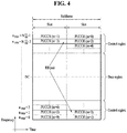
- FIG. 4 illustrates the structure of a UL subframe used in the 3GPP LTE/LTE-A system.
- a UL subframe may be divided into a data region and a control region in the frequency domain.
- One or several PUCCHs may be allocated to the control region to deliver UCI.
- One or several PUSCHs may be allocated to the data region of the UE subframe to carry user data.
- subcarriers distant from a direct current (DC) subcarrier are used as the control region.
- subcarriers located at both ends of a UL transmission BW are allocated to transmit UCI.
- a DC subcarrier is a component unused for signal transmission and is mapped to a carrier frequency f 0 in a frequency up-conversion process.
- a PUCCH for one UE is allocated to an RB pair belonging to resources operating on one carrier frequency and RBs belonging to the RB pair occupy different subcarriers in two slots.
- the PUCCH allocated in this way is expressed by frequency hopping of the RB pair allocated to the PUCCH over a slot boundary. If frequency hopping is not applied, the RB pair occupies the same subcarriers.
- the PUCCH may be used to transmit the following control information.
- the amount of uplink control information (UCI) that the UE may transmit in a subframe depends on the number of SC-FDMA symbols available for transmission of control information.
- the SC-FDMA symbols available for the UCI refer to the remaining SC-FDMA symbols except for SC-FDMA symbols used for RS transmission in an SC-FDMA subframe, and also except for the last SC-FDMA symbol in a subframe with a sounding reference signal (SRS).
- SRS sounding reference signal
- the RS is used for coherent detection of a PUCCH.
- the PUCCH supports various formats according to the amount of transmitted information.
- Table 4 illustrates mapping relationships between PUCCH formats and UCI in the LTE/LTE-A system.
- PUCCH format Modulation scheme Number of bits per subframe Usage Etc. 1 N/A N/A (exist or absent) SR (Scheduling Request) 1a BPSK 1 ACK/NACK or SR + ACK/NACK One codeword 1b QPSK 2 ACK/NACK or SR + ACK/NACK Two codeword 2 QPSK 20 CQI/PMI/RI Joint ACK/NACK (extended CP) 2a QPSK+BPSK 21 CQI/PMI/RI + ACK/NACK Normal CP only 2b QPSK+QPSK 22 CQI/PMI/RI + ACK/NACK Normal CP only 3 QPSK 48 ACK/NACK or SR + ACK/NACK or CQI/PMI/RI + ACK/NACK/NACK
- the PUCCH format 1 series are mainly used to deliver ACK/NACK information
- the PUCCH format 2 series are mainly used to deliver channel state information (CSI) such as CQI/PMI/RI
- the PUCCH format 3 series are mainly used to deliver ACK/NACK information.
- the signal When a packet is transmitted in a wireless communication system, the signal may be distorted during transmission because the packet is transmitted on a radio channel.
- a receiver To correctly receive the distorted signal, a receiver should compensate the received signal for the distortion based on channel information.
- channel information typically, a signal known to both the transmitter and the receiver is transmitted, and the channel information is obtained based on how much the signal is distorted during reception on the radio channel. This signal is called a pilot signal or a reference signal (RS).
- RS reference signal
- an RS should exist for each individual transmission antenna and more specifically for each individual antenna port.
- RSs may be classified into UL RSs and DL RSs. In the current LTE system, the following UL RSs are defined.
- RSs may be classified into two types according to their purposes: RS for obtaining channel information and RS for data demodulation. Because the former is used for a UE to acquire DL channel information, it should be transmitted over a wide band and received even at a UE which does not receive DL data in a specific subframe. The former is also used in a situation such as handover.
- the latter is an RS that an eNB transmits together with DL data in a corresponding resource, and a UE may demodulate data by receiving the RS and performing channel measurement. This RS should be transmitted in an area in which data is transmitted.
- OLPC open-loop power control
- CLPC closed-loop power control
- An OLPC parameter may be a factor for controlling power by estimating and compensating for attenuation of a DL signal from a serving cell (or serving eNB) to which the UE belongs. For example, if the distance between the UE and the serving cell increases and thus the DL signal is attenuated greatly, UL power may be controlled by increasing UL transmission power.
- a CLPC parameter is used to control UL power by directly transmitting information (e.g., a TPC command or the like) required to control UL transmission power by an eNB.
- UL transmission power control is performed in consideration of both of OLPC and CLPC.
- Equation 1 a description will be given of PUSCH transmission power determination for PUSCH transmission of a UE. Equation 1 below is used to determine the transmission power of the UE, when only a PUSCH is transmitted, not simultaneously with a PUCCH, in subslot/slot/subframe i in serving cell c.
- P PUSCH , c i min P CMAX , c i , 10 log 10 M PUSCH , c i + P O _ PUSCH , c j + ⁇ c j ⁇ PL c + ⁇ TF , c i + f c i dBm
- Equation 2 is used to determine PUSCH transmission power, when the PUCCH and the PUSCH are simultaneously transmitted in subframe i in serving cell c.
- P PUSCH , c i min 10 log 10 P ⁇ CMAX , c i ⁇ P ⁇ PUCCH i , 10 log 10 M PUSCH , c i + P O _ PUSCH , c j + ⁇ c j ⁇ PL c + ⁇ TF , c i + f c i dBm
- Equation 1 Parameters which will be described below in relation to Equation 1 and Equation 2 are used to determine UL transmission power of the UE in serving cell c.
- P CMAX,c ( i ) in Equation 1 represents maximum allowed transmission power of the UE in subslot/slot/subframe i
- P ⁇ CMAX,c ( i ) in Equation 2 represents a linear value of P CMAX,c ( i ).
- P ⁇ CMAX,c ( i ) in Equation 2 represents a linear value of P PUCCH ( i ) ( P PUCCH ( i ) represents PUCCH transmission power in subslot/slot/subframe i.
- M PUSCH,c ( i ) in Equation 1 is a parameter representing the bandwidth of a PUSCH resource allocation, expressed as the number of valid RBs for subframe i, which is allocated by the eNB.
- P O_PUSCH,c (j) is an eNB-indicated parameter which is the sum of a cell-specific nominal component P O_NOMINAL_PUSCH,c (j) provided by a higher layer and a UE-specific component P O_UE_PUSCH,c (j) provided by the higher layer.
- ⁇ c (j) which is a pathloss compensation factor provided by the higher layer, is a cell-specific parameter in 3 bits transmitted by the eNB.
- RSRP reference signal received power
- f c (i) is a value indicating a current PUSCH power control adjustment state for subslot/slot/subframe i.
- ⁇ PUSCH,c ( i - K PUSCH ) is signaled on a PDCCH together with DCI format 0/4 or DCI format 3/3A in subframe i-K PUSCH .
- f c (0) is the first value after the accumulated value is reset.
- K PUSCH the values of K PUSCH are defined as follows.
- K PUSCH is 4.
- TDD time division duplex
- K PUSCH has the values listed in Table 5 below.
- the least significant bit (LSB) of a UL index is set to 1
- LSB least significant bit
- K PUSCH 7.
- the values of K PUSCH are given in Table 5.
- the UE attempts to decode a PDCCH of DCI format 0/4 with a C-RNTI of the UE, or to decode a PDCCH of DCI format 3/3A with a TPC-PUSCH-RNTI of the UE and a DCI format for an SPS C-RNTI.
- DCI format 0/4 and DCI format 3/3A for serving cell c are detected in the same subframe, the UE should use ⁇ PUSCH,c provided in DCI format 0/4.
- ⁇ PUSCH,c 0 dB.
- ⁇ PUSCH,c 0dB.
- An accumulated value of ⁇ PUSCH,c signaled together with DCI format 3/3A on a PDCCH is one value of SET1 in Table 6, or one value of SET2 in Table 7 determined based on a TPC-index parameter provided by the higher layer.
- Table 6 TPC Command Field inDCI format 0/3/4 Accumulated ⁇ PUSCH,c [dB] Absolute ⁇ PUSCH,c [dB] only DCI format 0/4 0 -1 -4 1 0 -1 2 1 1 3 3 4
- Table 7 TPC Command Field in DCI format 3A Accumulated ⁇ PUSCH,c [dB] 0 -1 1 1
- f c ( i ) ⁇ PUSCH,c ( i - K PUSCH ) is satisfied.
- ⁇ PUSCH,c ( i - K PUSCH ) is signaled together with DCI format 0/4 on a PDCCH in subslot/slot/subframe i-K PUSCH .
- f c ( i ) f c ( i - 1) for a subframe/slot/subslot where no PDCCH with a DCI format is decoded for serving cell c, or where DRX occurs or i i is not an UL subframe in TDD.
- the first one of two types of values of f c (*) (accumulated value or current absolute value) is set as follows.
- f c (0) ⁇ P rampup,c + ⁇ msg 2, c where ⁇ msg 2 is a TPC command indicated by a random access response, and ⁇ P rampup corresponds to total power ramp-up from the first preamble to the last preamble and is provided by the higher layer.
- a TPC command is executed in an accumulation mode in UL power control (ULPC) in relation to the present disclosure, it is regulated in related technology to use an accumulated value in the following manner.
- ULPC UL power control
- Equation 3 is a related equation for ULPC of a PUCCH.
- P PUCCH i min P CMAX , c i , P 0 _ PUCCH + PL c + h n CQI n HARQ n SR + ⁇ F _ PUCCH F + ⁇ T ⁇ D F ′ + g i dBm
- Equation 3 i is a subslot/slot/subframe index, and c is a cell index. If the higher layer configures the UE to transmit a PUCCH through two antenna ports, the value of ⁇ TxD ( F ') is provided to the UE by the higher layer, and otherwise, ⁇ TxD ( F ') is 0.
- the parameters described below are for serving cell c.
- P CMAX,c ( i ) represents the maximum allowed transmission power of the UE and P 0_PUCCH is a parameter being the sum of cell-specific parameters, which are indicated by higher-layer signaling from the eNB.
- h(n) changes according to a PUCCH format
- n CQI is the number of information bits in a channel quality indicator (CQI)
- n HARQ is the number of HARQ bits
- n SR is the number of bits in an SR.
- a ⁇ F_PUCCH (F) value is a relative value with respect to PUCCH format 1a, which corresponds to PUCCH format (F) and is indicated by higher-layer signaling from the eNB.
- h(n CQI ,n HARQ ,n SR ) is dependent on a PUCCH format.
- n SR is 1, and otherwise, n SR is 0.
- Equation 4 h(n CQI ,n HARQ ,n SR ) is given by Equation 4 in the case of a normal cyclic prefix (CP) in PUCCH formats 2, 2a and 2b, and by Equation 5 in the case of an extended CP in PUCCH format 2.
- h n CQI n HARQ n SR ⁇ 10 log 10 n CQI 4 if n CQI ⁇ 4 0 otherwise
- h n CQI n HARQ n SR ⁇ 10 log 10 n CQI + n HARQ 4 if n CQI + n HARQ ⁇ 4 0 otherwise
- h(n CQI ,n HARQ ,n SR ) may be given by Equation 6 and otherwise, by Equation 7.
- h n CQI n HARQ n SR n HARQ + n SR ⁇ 1 3
- h n CQI n HARQ n SR n HARQ + n SR ⁇ 1 2
- Table 8 and Table 9 below list ⁇ PUCCH values in a TPC command field of a DCI format.
- Table 8 TPC Command Field in DCI format 1A/1B/1D/1/2A/2B/2C/2/3 ⁇ PUCCH [dB] 0 -1 1 0 2 1 3 3
- Table 9 TPC Command Field in DCI format 3A ⁇ PUCCH [dB] 0 -1 1 1
- TTIs transmission time intervals
- a TTI during which a physical channel such as a PDCCH/PDSCH/PUSCH/PUCCH is transmitted may be set to be less than 1msec to reduce latency for communication between an eNB and a UE according to a scenario (such a PDCCH/PDSCH/PUSCH/PUCCH is referred to as an sPDCCH/sPDSCH/sPUSCH/sPUCCH).
- a plurality of physical channels may exist in a single subframe (e.g., 1msec), and have different TTIs (or TTI lengths).
- TTIs or TTI lengths.
- a TTI may be 1msec (normal TTI), the length of a normal subframe used in the LTE system, and a short TTI is a TTI shorter than the normal TTI, spanning one or more OFDM or SC-FDMA symbols.
- the key features of the present disclosure may be extended to a TTI longer than one subframe or equal to or longer than 1ms.
- the key features of the present disclosure may also be extended to a short TTI which is introduced to the next-generation system by increasing a subcarrier spacing.
- the present disclosure is described in the context of LTE, for convenience, it is applicable to a technology using a different waveform/frame structure such as new radio access technology (RAT).
- RAT new radio access technology
- an sTTI may be configured in units of 3 OFDM symbols.
- a PDCCH i.e., sPDCCH
- a PDSCH i.e., sPDSCH
- a PDCCH i.e., sPDCCH
- a PDSCH i.e., sPDSCH
- a plurality of sTTIs may be configured with different OFDM symbols in one subframe.
- OFDM symbols included in the sTTI may be configured to exclude OFDM symbols carrying legacy control channels.
- an sPDCCH and an sPDSCH may be transmitted in time division multiplexing (TDM) in different OFDM symbol regions, or in frequency division multiplexing (FDM) in different PRB regions/frequency resources.
- TDM time division multiplexing
- FDM frequency division multiplexing
- data may be transmitted/scheduled in a sTTI in a UL environment, and channels corresponding to the existing TTI-based PUCCH and PUSCH are referred to as sPUCCH and sPUSCH.
- a 1-ms subframe includes 14 OFDM symbols in the case of a normal CP.
- a TTI is configured to be shorter than 1ms
- a plurality of TTIs may be included in one subframe.
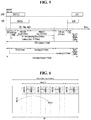
- two symbols, three symbols, four symbols, and seven symbols may be configured as one TTI, as illustrated in FIG. 7 .
- a TTI spanning one symbol may also be considered. If one symbol is one TTI unit, 12 TTIs are formed on the assumption that the legacy PDCCH is transmitted in two OFDM symbols. Similarly, as illustrated in FIG.
- TTI 7A when two symbols are one TTI unit, six TTIs may be formed. When three symbols are one TTI unit, four TTIs may be formed as illustrated in FIG. 7B . When four symbols are one TTI unit, three TTIs may be formed as illustrated in FIG. 7(c) . In this case, it is assumed that the legacy PDCCH is transmitted in the first two OFDM symbols.
- one TTI of seven symbols carrying the legacy PDCCH and one TTI of the next seven symbols may be configured.
- a UE supporting sTTI may assume that the first two OFDM symbols carrying the legacy PDCCH have been punctured or rate-matched and the following five symbols carry data and/or control information for the UE in the TTI (first slot) located at the former part of one subframe.
- the UE assumes that data and/or control information may be transmitted in all of the seven symbols without any puncturing or rate-matching resource regions.
- an sTTI structure in which an sTTI spanning two OFDM symbols (hereinafter, referred to as "OSs") coexists with an sTTI spanning three OSs as illustrated in FIG. 8 is also considered.
- a 2-OS or 3-OS sTTI may be simply defined as a 2-symbol sTTI (i.e., a 2-OS sTTI).
- a 2-symbol sTTI or 3-symbol sTTI may be referred to simply as a 2-symbol TTI or 3-symbol TTI. All of these sTTIs are shorter than the legacy 1-ms TTI according to the present disclosure. That is, despite the term "TTI", it does not mean that the TTI is not an sTTI, and the present disclosure relates to a communication scheme in a system configured with a TTI shorter than the legacy TTI, irrespective of the appellation.
- a numerology refers to determining the length of a TTI, a subcarrier spacing, and so on to be applied to the wireless communication system, a parameter such as a determined TTI length or subcarrier spacing, or a communication structure or system based on the parameter.
- an sPDCCH may also be transmitted according to the number of symbols in a PDCCH.
- transmission of an sPDCCH may be difficult because of the legacy PDCCH region.
- the number of symbols per slot is fixed to 12
- one subframe includes 4 slots.
- one resource block (RB) is defined as 12 consecutive subcarriers in the frequency domain, as in the legacy LTE system.
- each symbol in one slot may be defined according to a slot format, and both a DL symbol and a UL symbol may be configured in one slot. This case is referred to as a self-contained subframe (or slot) structure.
- TTI length and/or subcarrier spacing and/or quality of service (QoS)/latency requirement and/or reliability requirement e.g., a target block error rate (BLER)
- QoS quality of service
- reliability requirement e.g., a target block error rate (BLER)
- waveform e.g., DFT-s-OFDM or CP-OFDM
- CLPC of the UE is performed in an accumulation mode or in a non-accumulation mode (e.g., based on an absolute value indicated by a TPC).
- the configuration may be configured for the UE by higher-layer signaling or indicated to the UE by DCI.
- OLPC parameters e.g., P_0 and ⁇
- OLPC parameters may be configured independently for the UE.
- the parameters may be configured UE-specifically, and P0_NOMINAL_PUSCH,c/P0_NOMINAL_PUCCH may be configured cell-specifically and/or P0_UE_PUSCH,c/P0_UE_PUCCH may be configured independently for each TTI length and/or subcarrier spacing and/or QoS/latency requirement and/or reliability requirement(e.g., a target BLER) and/or waveform (e.g., DFT-s-OFDM or CP-OFDM).
- the configuration may be configured for the UE by higher-layer signaling or indicated to the UE by DCI.
- an accumulation reset operation may be configured independently for each TTI length and/or subcarrier spacing and/or QoS/latency requirement and/or reliability requirement (e.g., a target BLER) and/or waveform (e.g., DFT-s-OFDM or CP-OFDM).
- a target BLER e.g., a target BLER
- waveform e.g., DFT-s-OFDM or CP-OFDM
- P0_UE_PUSCH,c/P0_UE_PUCCH configured independently for each TTI length and/or subcarrier spacing and/or QoS/latency requirement and/or reliability requirement(e.g., a target BLER) and/or waveform (e.g., DFT-s-OFDM or CP-OFDM) is changed by the higher layer, accumulation is reset for a corresponding TTI length and/or subcarrier spacing and/or QoS/latency requirement and/or reliability requirement(e.g., a target BLER) and/or waveform (e.g., DFT-s-OFDM or CP-OFDM).
- a target BLER e.g., DFT-s-OFDM or CP-OFDM
- TTI length and/or subcarrier spacing and/or QoS/latency requirement and/or reliability requirement e.g., a target BLER
- waveform e.g., DFT-s-OFDM or CP-OFDM
- a TTI length and/or subcarrier spacing and/or QoS/latency requirement and/or reliability requirement(e.g., a target BLER) and/or waveform (e.g., DFT-s-OFDM or CP-OFDM) for which a TPC command transmitted in DCI is a parameter may be implicitly indicated by a search space and/or RNTI used for scrambling and/or format of the DCI.
- the UE When the UE is configured with a TTI length and/or subcarrier spacing and/or QoS/latency requirement and/or reliability requirement(e.g., a target BLER) and/or waveform (e.g., DFT-s-OFDM or CP-OFDM) different from a default value (or when the UE is configured with a plurality of TTI lengths and/or subcarrier spacings and/or QoS/latency requirements and/or reliability requirements (e.g., target BLERs) and/or waveforms (e.g., DFT-s-OFDM or CP-OFDM), it may not be preferable that the initial value of CLPC (functions of f and g) for the corresponding cell starts from 0.
- an accumulated value of a default (or specific criterion-based configured) TTI length and/or subcarrier spacing and/or QoS/latency requirement and/or reliability requirement e.g., a target BLER
- waveform e.g., DFT-s-OFDM or CP-OFDM
- Which time point's value is to be used may be informed to the UE by higher-layer signaling or physical-layer signaling to enable the same understanding between the eNB and the UE. For example, it may be regulated that an accumulated value of the default (or specific criterion-based configured) TTI length and/or subcarrier spacing and/or QoS/latency requirement and/or reliability requirement (e.g., a target BLER) and/or waveform (e.g., DFT-s-OFDM or CP-OFDM) a predetermined time (e.g., before 1ms or 1 sTTI) before a transmission time of an sTTI PUSCH/PUCCH is used as the initial value. This may be more useful when CLPC is performed independently, while OLPC parameters are shared.
- TTI length and/or subcarrier spacing and/or QoS/latency requirement and/or reliability requirement e.g., a target BLER
- waveform e.g., DFT-s
- DCI format 3/3A may also exist separately, and for each UE, DCI format 3/3A may be configured to include a TPC for each TTI length and/or subcarrier spacing and/or QoS/latency requirement and/or reliability requirement (e.g. target BLER) and/or waveform (e.g. DFT-s-OFDM or CP-OFDM).
- DCI format 3/3A may also exist separately, and for each UE, DCI format 3/3A may be configured to include a TPC for each TTI length and/or subcarrier spacing and/or QoS/latency requirement and/or reliability requirement (e.g. target BLER) and/or waveform (e.g. DFT-s-OFDM or CP-OFDM).
- a TPC-PUCCH-RNTI and/or a TPC-PUSCH-RNTI may exist for each TTI length and/or subcarrier spacing and/or QoS/latency requirement and/or reliability requirement (e.g. target BLER) and/or waveform (e.g. DFT-s-OFDM or CP-OFDM).
- a parameter e.g., the afore-described ⁇ TxD ( F ') in LTE UL power control
- ⁇ TxD ( F ') in LTE UL power control related to an MCS or coding rate for UL channel transmission power control (determination) may be configured independently.
- h(n CQI , n HARQ , n SR ) exists as one of power control parameters.
- the parameter serves to allow a PUCCH to be transmitted with higher power as the number of control bits transmitted on the PUCCH increases. For more details, refer to the description of the section "Transmit Power Control".
- the above power control rule may cause inefficient UL power allocation.
- the above power control rule may cause inefficient UL power allocation.
- an (s)PUCCH collides with another UL channel (of a different TTI length and/or a different type) and thus only the (s)PUCCH is transmitted, it is not clear whether to include, in n CQI , n HARQ , n SR , and so on, only the number of bits originally intended to be transmitted on the (s)PUCCH or even the number of bits intended to be transmitted on the other UL channel that has collided, and PUCCH transmission power based on the former will not be appropriate. Therefore, the following operations are proposed for the UE in the above situation.
- SPS semi-persistent scheduling
- TTI lengths and/or subcarrier spacings and/or QoS/latency requirements and/or reliability requirements e.g. target BLERs
- waveforms e.g. DFT-s-OFDM or CP-OFDM
- it is necessary to determine how to perform UL power control for each SPS.
- it may be considered to perform power control on the SPS of different TTI lengths and/or subcarrier spacings and/or QoS/latency requirements and/or reliability requirements (e.g. target BLERs) and/or waveforms (e.g. DFT-s-OFDM or CP-OFDM) by using DCI format 3/3A, which has been used for legacy SPS power control.
- DCI including power control information may be transmitted individually on a PDCCH of each TTI length and/or subcarrier spacing and/or QoS/latency requirement and/or reliability requirement (e.g. target BLER) and/or waveform (e.g. DFT-s-OFDM or CP-OFDM).
- the power control information may include TPC command information for CLPC.
- a 1ms-TTI SPS and an sTTI SPS may be separately subjected to power control, and for TPC commands for the power control, only a TPC from 1ms DCI may be considered for the 1ms-TTI SPS and only a TPC from sDCI may be considered for the sTTI SPS.
- This may amount to using a legacy TPC-PUCCH-RNTI/TPC-PUSCH-RNTI for CRC scrambling or configuring a separate RNTI for the UE.
- an (s)PDCCH in DCI format 3/3A including a TPC command or a DCI format modified/created based on DCI format 3/3A may be allowed to be transmitted in a different manner from in a legacy operation, and methods of transmitting an (s)PDCCH for sTTI SPS power control, including a possible scheme are proposed as follows. Further, the following options may be implemented independently of each other, or in combination of some or all of them.
- a cell-specific, UE group-specific, or UE-specific (s)PDCCH is transmitted by using the RNTI value for CRC scrambling, and the UE uses the (s)PDCCH in CLPC (e.g., TPC command-based power adjustment) for an SPS of a TTI length and/or subcarrier spacing and/or QoS/latency requirement and/or reliability requirement (e.g. target BLER) and/or waveform (e.g. DFT-s-OFDM or CP-OFDM) different from the configured default value.
- CLPC e.g., TPC command-based power adjustment
- SPS of a TTI length and/or subcarrier spacing and/or QoS/latency requirement and/or reliability requirement (e.g. target BLER) and/or waveform (e.g. DFT-s-OFDM or CP-OFDM) different from the configured default value.
- the (s)PDCCH for power control for the SPS of the TTI length and/or subcarrier spacing and/or QoS/latency requirement and/or reliability requirement e.g. target BLER
- waveform e.g. DFT-s-OFDM or CP-OFDM
- the control channel corresponding to the default TTI length and/or subcarrier spacing and/or QoS/latency requirement and/or reliability requirement (e.g. target BLER) and/or waveform (e.g. DFT-s-OFDM or CP-OFDM).
- a mapping relationship between a channel subjected to power adjustment and a control channel including information regarding the power adjustment in terms of TTI lengths and/or subcarrier spacings and/or QoS/latency requirements and/or reliability requirements (e.g. target BLERs) and/or waveforms (e.g. DFT-s-OFDM or CP-OFDM), may be predefined/preagreed, configured by higher-layer signaling, or indicated by physical-layer signaling (e.g., a group-PDCCH or group-common signal).
- TTI lengths and/or subcarrier spacings and/or QoS/latency requirements and/or reliability requirements e.g. target BLERs
- waveforms e.g. DFT-s-OFDM or CP-OFDM
- Option 8 Since a CSS may not be defined in the case of an sTTI, it may be difficult to introduce DCI format 3/3A including a TPC command or a cell-specific or group-common DCI format/signal modified/created based on DCI format 3/3A. Therefore, a TPC command for a specific TTI length and/or subcarrier spacing and/or QoS/latency requirement and/or reliability requirement (e.g. target BLER) and/or waveform (e.g. DFT-s-OFDM or CP-OFDM) may be also interpreted as a TPC command for a different TTI length and/or subcarrier spacing and/or QoS/latency requirement and/or reliability requirement (e.g.
- a TPC command for a specific TTI length and/or subcarrier spacing and/or QoS/latency requirement and/or reliability requirement e.g. target BLER
- waveform e.g. DFT-s-OFDM or CP-OFDM
- a DCI format (e.g., DCI format 3/3A) including a TPC command may be transmitted on a 1-ms TTI PDCCH, and the UE may read the TPC command according to configured information and use the TPC command for power adjustment in both of a 1-ms TTI and an sTTI.
- the starting CCE of a cell-specific or UE-group-specific (s)PDCCH for SPS power control or CCE-related information for decoding may be configured by higher-layer signaling or indicated by physical-layer signaling.
- P_0 parameters P_0_UE_PUSCH,c or P_0_UE_PUCCH
- a parameter for a reference TTI length (1ms TTI) is reused.
- initial value setting or accumulation reset may be performed differently from intended.
- the rule for setting the initial value of the power control adjustment state for the sTTI of a specific carrier for which the sTTI operation is configured does not exist in the current standard document, and the accumulation reset operation may not be performed.
- the accumulation reset operation may not be performed.
- TTI length and/or subcarrier spacing and/or QoS/latency requirement and/or reliability requirement e.g. target BLER
- waveform e.g. DFT-s-OFDM or CP-OFDM
- the initial value for power control adjustment is set to 0 and/or an accumulation reset operation is performed, for the corresponding TTI length and/or numerology and/or processing time and/or QoS/latency requirement and/or reliability requirement (e.g. target BLER) and/or waveform.
- this operation may be performed regardless of whether the value of P_0_UE_PUSCH,c or P_0_UE_PUCCH is changed.
- it may be regulated that, when an sTTI is additionally configured for the UE already configured only with the legacy TTI length (i.e., 1ms), the initial value of power control adjustment for the sTTI is set to 0 and/or an accumulation reset operation is performed.
- TTI length and/or numerology and/or processing time and/or QoS/latency requirement and/or reliability requirement e.g. target BLER
- the initial value for power control adjustment is set to 0 and/or an accumulation reset operation is performed, for the corresponding TTI length and/or numerology and/or processing time and/or QoS/latency requirement and/or reliability requirement (e.g. target BLER) and/or waveform.
- this operation may be performed regardless of whether the value of P_0_UE_PUSCH,c or P_0_UE_PUCCH is changed.
- the initial value of power control adjustment for the sTTI is set to 0 and/or an accumulation reset operation is performed.
- the operation of setting an initial value to 0 and/or the accumulation reset operation is not performed under the determination of the network. It may be indicated to/configured for the UE whether the initial value is set to 0 and/or the accumulation reset operation is performed, by physical-layer/higher-layer signaling.
- the operation of setting an initial value to 0 in the proposals may include an operation of setting the initial value to a specific value predefined, or configured by physical-layer/higher-layer signaling.
- FIG. 9 is a block diagram illustrating elements of a transmitting device 10 and a receiving device 20 for implementing the present disclosure.
- the transmitting device 10 and the receiving device 20 respectively include transceivers 13 and 23 capable of transmitting and receiving radio signals carrying information, data, signals, and/or messages, memories 12 and 22 for storing information related to communication in a wireless communication system, and processors 11 and 21 operationally connected to elements such as the transceivers 13 and 23 and the memories 12 and 22 to control the elements and configured to control the memories 12 and 22 and/or the transceivers 13 and 23 so that a corresponding device may perform at least one of the above-described examples of the present disclosure.
- the memories 12 and 22 may store programs for processing and controlling the processors 11 and 21 and may temporarily store input/output information.
- the memories 12 and 22 may be used as buffers.
- the processors 11 and 21 generally control the overall operation of various modules in the transmitting device and the receiving device. Especially, the processors 11 and 21 may perform various control functions to implement the present disclosure.
- the processors 11 and 21 may be referred to as controllers, microcontrollers, microprocessors, or microcomputers.
- the processors 11 and 21 may be implemented by hardware, firmware, software, or a combination thereof.
- ASICs application specific integrated circuits
- DSPs digital signal processors
- DSPDs digital signal processing devices
- PLDs programmable logic devices
- FPGAs field programmable gate arrays
- firmware or software may be configured to include modules, procedures, functions, etc. performing the functions or operations of the present disclosure.
- Firmware or software configured to perform the present disclosure may be included in the processors 11 and 21 or stored in the memories 12 and 22 so as to be driven by the processors 11 and 21.
- the processor 11 of the transmitting device 10 performs predetermined coding and modulation for a signal and/or data scheduled to be transmitted to the outside by the processor 11 or a scheduler connected with the processor 11, and then transfers the coded and modulated data to the transceiver 13.
- the processor 11 converts a data stream to be transmitted into K layers through demultiplexing, channel coding, scrambling, and modulation.
- the coded data stream is also referred to as a codeword and is equivalent to a transport block which is a data block provided by a MAC layer.
- One transport block (TB) is coded into one codeword and each codeword is transmitted to the receiving device in the form of one or more layers.
- the transceiver 13 may include an oscillator.
- the transceiver 13 may include N t (where N t is a positive integer) transmit antennas.
- a signal processing process of the receiving device 20 is the reverse of the signal processing process of the transmitting device 10.
- the transceiver 23 of the receiving device 20 receives radio signals transmitted by the transmitting device 10.
- the transceiver 23 may include N r (where N r is a positive integer) receive antennas and frequency down-converts each signal received through receive antennas into a baseband signal.
- the processor 21 decodes and demodulates the radio signals received through the receive antennas and restores data that the transmitting device 10 intended to transmit.
- the transceivers 13 and 23 include one or more antennas.
- An antenna performs a function for transmitting signals processed by the transceivers 13 and 23 to the exterior or receiving radio signals from the exterior to transfer the radio signals to the transceivers 13 and 23.
- the antenna may also be called an antenna port.
- Each antenna may correspond to one physical antenna or may be configured by a combination of more than one physical antenna element.
- the signal transmitted from each antenna cannot be further deconstructed by the receiving device 20.
- An RS transmitted through a corresponding antenna defines an antenna from the view point of the receiving device 20 and enables the receiving device 20 to derive channel estimation for the antenna, irrespective of whether the channel represents a single radio channel from one physical antenna or a composite channel from a plurality of physical antenna elements including the antenna.
- an antenna is defined such that a channel carrying a symbol of the antenna can be obtained from a channel carrying another symbol of the same antenna.
- a transceiver supporting a MIMO function of transmitting and receiving data using a plurality of antennas may be connected to two or more antennas.
- a terminal or UE operates as the transmitting device 10 in UL and as the receiving device 20 in DL.
- a BS or eNB operates as the receiving device 20 in UL and as the transmitting device 10 in DL.
- the transmitting device and/or the receiving device may implement at least one or more of the foregoing examples of the present disclosure in combination.
- a terminal for determining transmission power in a wireless communication system may include a receiver and a transmitter, and a processor configured to control the receiver and the transmitter.
- the processor may be configured to receive a configuration of SPS for an sTTI, receive control information for controlling a transmission power related to the SPS according to the received configuration, and determine the transmission power related to the SPS using a transmit power control (TPC) command included in the received control information.
- the control information may include respective TPC commands for a plurality of TTI lengths, including a TPC command related to the SPS of the sTTI.
- transmission power control of the terminal is an accumulated value-based operation or an absolute value-based operation may be configured for each TTI length.
- an initial value of a power control adjustment state used to determine the transmission power related to the SPS may be set to 0 after reset.
- the processor may be configured to reset accumulation for the serving cell.
- an initial value of a power control adjustment state used to determine the transmission power related to the SPS may be set to an accumulated value based on a TTI of a predetermined length, after reset.
- control information may be received on a control channel based on a TTI of a predetermined length.
- an identifier used to scramble the control information may be different from an identifier used to scramble control information based on a TTI of a predetermined length.
- the present disclosure is applicable to wireless communication devices such as a terminal, a relay, a BS and the like.
Landscapes
- Engineering & Computer Science (AREA)
- Signal Processing (AREA)
- Computer Networks & Wireless Communication (AREA)
- Mobile Radio Communication Systems (AREA)
Applications Claiming Priority (7)
| Application Number | Priority Date | Filing Date | Title |
|---|---|---|---|
| US201762505793P | 2017-05-12 | 2017-05-12 | |
| US201762537944P | 2017-07-27 | 2017-07-27 | |
| US201762560677P | 2017-09-20 | 2017-09-20 | |
| US201762570674P | 2017-10-11 | 2017-10-11 | |
| US201762576118P | 2017-10-24 | 2017-10-24 | |
| US201762584057P | 2017-11-09 | 2017-11-09 | |
| PCT/KR2018/005495 WO2018208134A1 (fr) | 2017-05-12 | 2018-05-14 | Procédé de commande de puissance de transmission dans un système de communication sans fil et appareil associé |
Publications (3)
| Publication Number | Publication Date |
|---|---|
| EP3637882A1 true EP3637882A1 (fr) | 2020-04-15 |
| EP3637882A4 EP3637882A4 (fr) | 2020-11-25 |
| EP3637882B1 EP3637882B1 (fr) | 2022-07-06 |
Family
ID=64105372
Family Applications (1)
| Application Number | Title | Priority Date | Filing Date |
|---|---|---|---|
| EP18799025.4A Active EP3637882B1 (fr) | 2017-05-12 | 2018-05-14 | Procédé de commande de puissance de transmission dans un système de communication sans fil et appareil associé |
Country Status (6)
| Country | Link |
|---|---|
| US (1) | US11102734B2 (fr) |
| EP (1) | EP3637882B1 (fr) |
| JP (2) | JP6961718B2 (fr) |
| KR (1) | KR101976053B1 (fr) |
| CN (1) | CN110612754B (fr) |
| WO (1) | WO2018208134A1 (fr) |
Cited By (1)
| Publication number | Priority date | Publication date | Assignee | Title |
|---|---|---|---|---|
| US11291026B2 (en) * | 2017-11-09 | 2022-03-29 | Qualcomm Incorporated | Uplink transmission techniques in low-latency wireless communication |
Families Citing this family (6)
| Publication number | Priority date | Publication date | Assignee | Title |
|---|---|---|---|---|
| JP6961718B2 (ja) | 2017-05-12 | 2021-11-05 | エルジー エレクトロニクス インコーポレイティドLg Electronics Inc. | 無線通信システムにおいて送信電力制御のための方法及びそのための装置 |
| US11516747B2 (en) * | 2017-05-12 | 2022-11-29 | Lg Electronics Inc. | Method for controlling transmit power in wireless communication system and apparatus therefor |
| US20220182945A1 (en) * | 2017-11-09 | 2022-06-09 | Qualcomm Incorporated | Uplink transmission techniques in low-latency wireless communication |
| WO2019138517A1 (fr) * | 2018-01-11 | 2019-07-18 | 株式会社Nttドコモ | Terminal utilisateur et procédé de communication sans fil |
| CN117439723A (zh) * | 2018-05-11 | 2024-01-23 | 华为技术有限公司 | 通信的方法和通信装置 |
| JP7105132B2 (ja) * | 2018-08-06 | 2022-07-22 | Kddi株式会社 | レガシーシステムとの共存を実行するための通信装置、通信方法、及びプログラム |
Family Cites Families (43)
| Publication number | Priority date | Publication date | Assignee | Title |
|---|---|---|---|---|
| CN101174859A (zh) * | 2006-10-30 | 2008-05-07 | 中兴通讯股份有限公司 | 用于td-scdma系统上行功率增强的功率控制系统及方法 |
| EP2589157A1 (fr) * | 2010-06-30 | 2013-05-08 | Telefonaktiebolaget LM Ericsson (publ) | Procédé utilisant un signal d'occultation pour réduire la fuite d'un émetteur-récepteur |
| KR102049729B1 (ko) | 2011-01-05 | 2019-11-28 | 선 페이턴트 트러스트 | 단말 장치, 통신 방법, 기지국 장치 및 집적 회로 |
| EP2774429A1 (fr) * | 2011-11-04 | 2014-09-10 | Telefonaktiebolaget L M Ericsson (publ) | Procédé et dispositif de commande de puissance d'émission |
| US9516638B2 (en) * | 2012-06-20 | 2016-12-06 | Lg Electronics Inc. | Signal transmission/reception method and apparatus therefor |
| KR20150016473A (ko) | 2013-08-02 | 2015-02-12 | 한국전자통신연구원 | 상향 링크 스케줄링 방법 및 상향링크 전송 방법 |
| CN110856242B (zh) * | 2014-01-29 | 2023-07-25 | 交互数字专利控股公司 | 无线通信中的上行链路传输 |
| US9980281B2 (en) | 2014-08-06 | 2018-05-22 | Lg Electronics Inc. | Method for performing transmission power control in wireless communication system and device therefor |
| US9955462B2 (en) | 2014-09-26 | 2018-04-24 | Qualcomm Incorporated | Ultra-low latency LTE control data communication |
| WO2016064039A1 (fr) | 2014-10-21 | 2016-04-28 | 엘지전자(주) | Procédé d'émission/réception de données dans un système de communication sans fil qui supporte un faible temps de latence, et appareil correspondant |
| US9900843B2 (en) | 2015-01-12 | 2018-02-20 | Qualcomm Incorporated | Uplink power control techniques for ultra low latency in LTE devices |
| US10149255B2 (en) | 2015-05-01 | 2018-12-04 | Qualcomm Incorporated | Low latency uplink power control |
| US9775141B2 (en) | 2015-07-14 | 2017-09-26 | Motorola Mobility Llc | Method and apparatus for reducing latency of LTE uplink transmissions |
| US20180199314A1 (en) * | 2015-07-15 | 2018-07-12 | Ntt Docomo, Inc. | User terminal, radio base station, and radio communication method |
| KR102340499B1 (ko) | 2015-09-04 | 2021-12-17 | 삼성전자 주식회사 | 무선통신 시스템에서 상향링크 전송전력 제어 방법 및 장치 |
| US10973078B2 (en) | 2015-09-25 | 2021-04-06 | Apple Inc. | Supporting semi-persistent scheduling for varied transmission time intervals |
| US20170111923A1 (en) * | 2015-10-14 | 2017-04-20 | Sharp Laboratories Of America, Inc. | User equipments, base stations and methods for low latency radio communications |
| US10568040B2 (en) | 2016-02-19 | 2020-02-18 | Ntt Docomo, Inc. | Terminal and radio communication method |
| WO2017166245A1 (fr) * | 2016-03-31 | 2017-10-05 | 华为技术有限公司 | Procédé de gestion de ressource et équipement associé |
| EP3907920B1 (fr) | 2016-03-31 | 2023-03-01 | Panasonic Intellectual Property Corporation of America | Configuration de sous-trame spéciale destinée à une réduction de latence |
| US10172156B2 (en) * | 2016-09-12 | 2019-01-01 | Motorola Mobility Llc | Method and apparatus for scheduling uplink transmissions with reduced latency |
| US10277367B2 (en) * | 2016-04-01 | 2019-04-30 | Motorola Mobility Llc | Method and apparatus for scheduling uplink transmissions with reduced latency |
| US10117188B2 (en) * | 2016-04-01 | 2018-10-30 | Motorola Mobility Llc | Method and apparatus for scheduling uplink transmissions with reduced latency |
| US10420079B2 (en) | 2016-04-01 | 2019-09-17 | Hfi Innovation Inc. | Efficient control and data multiplexing in communication systems |
| US10542503B2 (en) * | 2016-04-01 | 2020-01-21 | Motorola Mobility Llc | Method and apparatus for scheduling uplink transmissions with reduced latency |
| US10412620B2 (en) * | 2016-04-01 | 2019-09-10 | Motorola Mobility Llc | Method and apparatus for scheduling uplink transmissions with reduced latency |
| US10069613B2 (en) * | 2016-04-01 | 2018-09-04 | Motorola Mobility Llc | Method and apparatus for scheduling uplink transmissions with reduced latency |
| CN107396394B (zh) | 2016-05-12 | 2020-04-07 | 华硕电脑股份有限公司 | 短传输时间间隔的上行链路传输的方法 |
| KR20190017994A (ko) * | 2016-06-15 | 2019-02-20 | 콘비다 와이어리스, 엘엘씨 | 새로운 라디오를 위한 업로드 제어 시그널링 |
| CN107613553B (zh) * | 2016-07-11 | 2019-11-22 | 电信科学技术研究院 | 一种上行传输功率控制的方法及装置 |
| US10985966B2 (en) | 2016-08-09 | 2021-04-20 | Panasonic Intellectual Property Corporation Of America | Terminal and communication method |
| SG11201901003UA (en) * | 2016-08-12 | 2019-03-28 | Beijing Xiaomi Mobile Software Co Ltd | Resource scheduling method, scheduler, base station, terminal, and system |
| US11540225B2 (en) | 2016-09-14 | 2022-12-27 | Ntt Docomo, Inc. | User terminal and radio communication method |
| CN107889266B (zh) | 2016-09-30 | 2022-09-27 | 中兴通讯股份有限公司 | 物理下行共享信道pusch的传输方法及装置 |
| US10708864B2 (en) | 2016-09-30 | 2020-07-07 | Telefonaktiebolaget Lm Ericsson (Publ) | Power control of physical channels having different transmission time intervals based on respective power control loops |
| JP7187452B2 (ja) * | 2016-10-19 | 2022-12-12 | アイピーエルエー ホールディングス インコーポレイテッド | 装置 |
| ES2914231T3 (es) * | 2016-10-21 | 2022-06-08 | Asustek Comp Inc | Procedimiento y aparato para el reporte de margen de tolerancia de potencia para la operación del haz en un sistema de comunicación inalámbrico |
| EP3539329A4 (fr) | 2016-11-14 | 2020-06-24 | Telefonaktiebolaget LM Ericsson (PUBL) | Adaptation de paramètre de commande d'émission d'ue dans des tti se chevauchant |
| EP3579478B1 (fr) * | 2017-02-02 | 2021-07-28 | LG Electronics Inc. | Procédé de prise en charge de multiples intervalles de temps de transmission, de multiples intervalles de sous-porteuse ou de multiples intervalles de temps de traitement dans un système de communication sans fil et appareil associé |
| CN109845180B (zh) * | 2017-04-01 | 2022-04-15 | Lg 电子株式会社 | 无线通信系统中用于支持短传输时间间隔的终端发送或者接收上行链路信号的方法及其装置 |
| JP6961718B2 (ja) | 2017-05-12 | 2021-11-05 | エルジー エレクトロニクス インコーポレイティドLg Electronics Inc. | 無線通信システムにおいて送信電力制御のための方法及びそのための装置 |
| US11516747B2 (en) * | 2017-05-12 | 2022-11-29 | Lg Electronics Inc. | Method for controlling transmit power in wireless communication system and apparatus therefor |
| JPWO2018207372A1 (ja) | 2017-05-12 | 2020-03-26 | 株式会社Nttドコモ | ユーザ端末及び無線通信方法 |
-
2018
- 2018-05-14 JP JP2019561735A patent/JP6961718B2/ja active Active
- 2018-05-14 WO PCT/KR2018/005495 patent/WO2018208134A1/fr active Application Filing
- 2018-05-14 EP EP18799025.4A patent/EP3637882B1/fr active Active
- 2018-05-14 KR KR1020180054928A patent/KR101976053B1/ko active IP Right Grant
- 2018-05-14 CN CN201880031315.9A patent/CN110612754B/zh active Active
- 2018-05-14 US US16/611,396 patent/US11102734B2/en active Active
-
2021
- 2021-10-13 JP JP2021167854A patent/JP7350034B2/ja active Active
Cited By (1)
| Publication number | Priority date | Publication date | Assignee | Title |
|---|---|---|---|---|
| US11291026B2 (en) * | 2017-11-09 | 2022-03-29 | Qualcomm Incorporated | Uplink transmission techniques in low-latency wireless communication |
Also Published As
| Publication number | Publication date |
|---|---|
| WO2018208134A1 (fr) | 2018-11-15 |
| EP3637882A4 (fr) | 2020-11-25 |
| CN110612754B (zh) | 2022-08-02 |
| US11102734B2 (en) | 2021-08-24 |
| JP2020520168A (ja) | 2020-07-02 |
| EP3637882B1 (fr) | 2022-07-06 |
| KR101976053B1 (ko) | 2019-05-08 |
| CN110612754A (zh) | 2019-12-24 |
| JP2022009070A (ja) | 2022-01-14 |
| US20200389859A1 (en) | 2020-12-10 |
| KR20180124790A (ko) | 2018-11-21 |
| JP7350034B2 (ja) | 2023-09-25 |
| JP6961718B2 (ja) | 2021-11-05 |
Similar Documents
| Publication | Publication Date | Title |
|---|---|---|
| EP3637878B1 (fr) | Procédé de transmission d'un signal de liaison montante dans un système de communication sans fil et dispositif associé | |
| EP3413496B1 (fr) | Procédé pour mapper et transmettre des informations de commande de liaison montante dans un système de communication sans fil, et dispositif associé | |
| US10798664B2 (en) | Method and apparatus for reporting power headroom in wireless communication system | |
| EP3637882B1 (fr) | Procédé de commande de puissance de transmission dans un système de communication sans fil et appareil associé | |
| US11071130B2 (en) | Method for supporting plurality of transmission time intervals, plurality of subcarrier intervals or plurality of processing times in wireless communication system, and device therefor | |
| US11516747B2 (en) | Method for controlling transmit power in wireless communication system and apparatus therefor | |
| EP3703453A1 (fr) | Procédé de transmission ou de réception de signal dans un système de communication sans fil et dispositif associé | |
| EP3522642B1 (fr) | Procédé destiné à une pluralité de temps de traitement ou une pluralité d'intervalles de temps de transmission dans un système de communication sans fil, et appareil associé | |
| EP3579478A1 (fr) | Procédé de prise en charge de multiples intervalles de temps de transmission, de multiples intervalles de sous-porteuse ou de multiples intervalles de temps de traitement dans un système de communication sans fil et appareil associé | |
| EP3637928B1 (fr) | Procédé et dispositif pour recevoir un signal de liaison descendante dans un système de communication sans fil | |
| EP3468093B1 (fr) | Procédé d'émission ou de réception d'un signal de liaison montante prenant en charge un intervalle de temps d'émission court dans un système de communication sans fil et dispositif associé | |
| EP3554159B1 (fr) | Procédé de prise en charge d'une pluralité d'intervalles de temps de transmission dans un système de communication sans fil, et appareil associé | |
| US11206617B2 (en) | Method and apparatus for uplink repetition on basis of semi-persistent scheduling | |
| EP3605887A1 (fr) | Procédé pour mesure d'état de canal dans un système de communication sans fil et appareil associé | |
| US20230155748A1 (en) | Method for harq feedback in wireless communication system and apparatus therefor |
Legal Events
| Date | Code | Title | Description |
|---|---|---|---|
| STAA | Information on the status of an ep patent application or granted ep patent |
Free format text: STATUS: THE INTERNATIONAL PUBLICATION HAS BEEN MADE |
|
| PUAI | Public reference made under article 153(3) epc to a published international application that has entered the european phase |
Free format text: ORIGINAL CODE: 0009012 |
|
| STAA | Information on the status of an ep patent application or granted ep patent |
Free format text: STATUS: REQUEST FOR EXAMINATION WAS MADE |
|
| 17P | Request for examination filed |
Effective date: 20191209 |
|
| AK | Designated contracting states |
Kind code of ref document: A1 Designated state(s): AL AT BE BG CH CY CZ DE DK EE ES FI FR GB GR HR HU IE IS IT LI LT LU LV MC MK MT NL NO PL PT RO RS SE SI SK SM TR |
|
| AX | Request for extension of the european patent |
Extension state: BA ME |
|
| DAV | Request for validation of the european patent (deleted) | ||
| DAX | Request for extension of the european patent (deleted) | ||
| A4 | Supplementary search report drawn up and despatched |
Effective date: 20201028 |
|
| RIC1 | Information provided on ipc code assigned before grant |
Ipc: H04W 52/10 20090101ALI20201022BHEP Ipc: H04W 72/12 20090101ALI20201022BHEP Ipc: H04W 52/14 20090101ALI20201022BHEP Ipc: H04W 52/08 20090101ALI20201022BHEP Ipc: H04W 52/04 20090101ALI20201022BHEP Ipc: H04W 52/54 20090101AFI20201022BHEP Ipc: H04W 52/02 20090101ALI20201022BHEP Ipc: H04W 72/04 20090101ALI20201022BHEP |
|
| RIC1 | Information provided on ipc code assigned before grant |
Ipc: H04W 72/04 20090101ALI20211104BHEP Ipc: H04W 52/10 20090101ALI20211104BHEP Ipc: H04W 52/08 20090101ALI20211104BHEP Ipc: H04W 52/04 20090101ALI20211104BHEP Ipc: H04W 52/02 20090101ALI20211104BHEP Ipc: H04W 52/14 20090101ALI20211104BHEP Ipc: H04W 72/12 20090101ALI20211104BHEP Ipc: H04W 52/54 20090101AFI20211104BHEP |
|
| GRAP | Despatch of communication of intention to grant a patent |
Free format text: ORIGINAL CODE: EPIDOSNIGR1 |
|
| STAA | Information on the status of an ep patent application or granted ep patent |
Free format text: STATUS: GRANT OF PATENT IS INTENDED |
|
| INTG | Intention to grant announced |
Effective date: 20211221 |
|
| GRAS | Grant fee paid |
Free format text: ORIGINAL CODE: EPIDOSNIGR3 |
|
| GRAA | (expected) grant |
Free format text: ORIGINAL CODE: 0009210 |
|
| STAA | Information on the status of an ep patent application or granted ep patent |
Free format text: STATUS: THE PATENT HAS BEEN GRANTED |
|
| AK | Designated contracting states |
Kind code of ref document: B1 Designated state(s): AL AT BE BG CH CY CZ DE DK EE ES FI FR GB GR HR HU IE IS IT LI LT LU LV MC MK MT NL NO PL PT RO RS SE SI SK SM TR |
|
| REG | Reference to a national code |
Ref country code: AT Ref legal event code: REF Ref document number: 1503770 Country of ref document: AT Kind code of ref document: T Effective date: 20220715 Ref country code: CH Ref legal event code: EP |
|
| REG | Reference to a national code |
Ref country code: DE Ref legal event code: R096 Ref document number: 602018037662 Country of ref document: DE |
|
| REG | Reference to a national code |
Ref country code: IE Ref legal event code: FG4D |
|
| REG | Reference to a national code |
Ref country code: LT Ref legal event code: MG9D |
|
| REG | Reference to a national code |
Ref country code: NL Ref legal event code: MP Effective date: 20220706 |
|
| PG25 | Lapsed in a contracting state [announced via postgrant information from national office to epo] |
Ref country code: SE Free format text: LAPSE BECAUSE OF FAILURE TO SUBMIT A TRANSLATION OF THE DESCRIPTION OR TO PAY THE FEE WITHIN THE PRESCRIBED TIME-LIMIT Effective date: 20220706 Ref country code: RS Free format text: LAPSE BECAUSE OF FAILURE TO SUBMIT A TRANSLATION OF THE DESCRIPTION OR TO PAY THE FEE WITHIN THE PRESCRIBED TIME-LIMIT Effective date: 20220706 Ref country code: PT Free format text: LAPSE BECAUSE OF FAILURE TO SUBMIT A TRANSLATION OF THE DESCRIPTION OR TO PAY THE FEE WITHIN THE PRESCRIBED TIME-LIMIT Effective date: 20221107 Ref country code: NO Free format text: LAPSE BECAUSE OF FAILURE TO SUBMIT A TRANSLATION OF THE DESCRIPTION OR TO PAY THE FEE WITHIN THE PRESCRIBED TIME-LIMIT Effective date: 20221006 Ref country code: NL Free format text: LAPSE BECAUSE OF FAILURE TO SUBMIT A TRANSLATION OF THE DESCRIPTION OR TO PAY THE FEE WITHIN THE PRESCRIBED TIME-LIMIT Effective date: 20220706 Ref country code: LV Free format text: LAPSE BECAUSE OF FAILURE TO SUBMIT A TRANSLATION OF THE DESCRIPTION OR TO PAY THE FEE WITHIN THE PRESCRIBED TIME-LIMIT Effective date: 20220706 Ref country code: LT Free format text: LAPSE BECAUSE OF FAILURE TO SUBMIT A TRANSLATION OF THE DESCRIPTION OR TO PAY THE FEE WITHIN THE PRESCRIBED TIME-LIMIT Effective date: 20220706 Ref country code: FI Free format text: LAPSE BECAUSE OF FAILURE TO SUBMIT A TRANSLATION OF THE DESCRIPTION OR TO PAY THE FEE WITHIN THE PRESCRIBED TIME-LIMIT Effective date: 20220706 Ref country code: ES Free format text: LAPSE BECAUSE OF FAILURE TO SUBMIT A TRANSLATION OF THE DESCRIPTION OR TO PAY THE FEE WITHIN THE PRESCRIBED TIME-LIMIT Effective date: 20220706 |
|
| REG | Reference to a national code |
Ref country code: AT Ref legal event code: MK05 Ref document number: 1503770 Country of ref document: AT Kind code of ref document: T Effective date: 20220706 |
|
| PG25 | Lapsed in a contracting state [announced via postgrant information from national office to epo] |
Ref country code: PL Free format text: LAPSE BECAUSE OF FAILURE TO SUBMIT A TRANSLATION OF THE DESCRIPTION OR TO PAY THE FEE WITHIN THE PRESCRIBED TIME-LIMIT Effective date: 20220706 Ref country code: IS Free format text: LAPSE BECAUSE OF FAILURE TO SUBMIT A TRANSLATION OF THE DESCRIPTION OR TO PAY THE FEE WITHIN THE PRESCRIBED TIME-LIMIT Effective date: 20221106 Ref country code: HR Free format text: LAPSE BECAUSE OF FAILURE TO SUBMIT A TRANSLATION OF THE DESCRIPTION OR TO PAY THE FEE WITHIN THE PRESCRIBED TIME-LIMIT Effective date: 20220706 Ref country code: GR Free format text: LAPSE BECAUSE OF FAILURE TO SUBMIT A TRANSLATION OF THE DESCRIPTION OR TO PAY THE FEE WITHIN THE PRESCRIBED TIME-LIMIT Effective date: 20221007 |
|
| REG | Reference to a national code |
Ref country code: DE Ref legal event code: R097 Ref document number: 602018037662 Country of ref document: DE |
|
| PG25 | Lapsed in a contracting state [announced via postgrant information from national office to epo] |
Ref country code: SM Free format text: LAPSE BECAUSE OF FAILURE TO SUBMIT A TRANSLATION OF THE DESCRIPTION OR TO PAY THE FEE WITHIN THE PRESCRIBED TIME-LIMIT Effective date: 20220706 Ref country code: RO Free format text: LAPSE BECAUSE OF FAILURE TO SUBMIT A TRANSLATION OF THE DESCRIPTION OR TO PAY THE FEE WITHIN THE PRESCRIBED TIME-LIMIT Effective date: 20220706 Ref country code: DK Free format text: LAPSE BECAUSE OF FAILURE TO SUBMIT A TRANSLATION OF THE DESCRIPTION OR TO PAY THE FEE WITHIN THE PRESCRIBED TIME-LIMIT Effective date: 20220706 Ref country code: CZ Free format text: LAPSE BECAUSE OF FAILURE TO SUBMIT A TRANSLATION OF THE DESCRIPTION OR TO PAY THE FEE WITHIN THE PRESCRIBED TIME-LIMIT Effective date: 20220706 Ref country code: AT Free format text: LAPSE BECAUSE OF FAILURE TO SUBMIT A TRANSLATION OF THE DESCRIPTION OR TO PAY THE FEE WITHIN THE PRESCRIBED TIME-LIMIT Effective date: 20220706 |
|
| PLBE | No opposition filed within time limit |
Free format text: ORIGINAL CODE: 0009261 |
|
| STAA | Information on the status of an ep patent application or granted ep patent |
Free format text: STATUS: NO OPPOSITION FILED WITHIN TIME LIMIT |
|
| PG25 | Lapsed in a contracting state [announced via postgrant information from national office to epo] |
Ref country code: SK Free format text: LAPSE BECAUSE OF FAILURE TO SUBMIT A TRANSLATION OF THE DESCRIPTION OR TO PAY THE FEE WITHIN THE PRESCRIBED TIME-LIMIT Effective date: 20220706 Ref country code: EE Free format text: LAPSE BECAUSE OF FAILURE TO SUBMIT A TRANSLATION OF THE DESCRIPTION OR TO PAY THE FEE WITHIN THE PRESCRIBED TIME-LIMIT Effective date: 20220706 |
|
| 26N | No opposition filed |
Effective date: 20230411 |
|
| PG25 | Lapsed in a contracting state [announced via postgrant information from national office to epo] |
Ref country code: AL Free format text: LAPSE BECAUSE OF FAILURE TO SUBMIT A TRANSLATION OF THE DESCRIPTION OR TO PAY THE FEE WITHIN THE PRESCRIBED TIME-LIMIT Effective date: 20220706 |
|
| P01 | Opt-out of the competence of the unified patent court (upc) registered |
Effective date: 20230527 |
|
| PGFP | Annual fee paid to national office [announced via postgrant information from national office to epo] |
Ref country code: IT Payment date: 20230406 Year of fee payment: 6 Ref country code: FR Payment date: 20230405 Year of fee payment: 6 Ref country code: DE Payment date: 20230405 Year of fee payment: 6 |
|
| PG25 | Lapsed in a contracting state [announced via postgrant information from national office to epo] |
Ref country code: SI Free format text: LAPSE BECAUSE OF FAILURE TO SUBMIT A TRANSLATION OF THE DESCRIPTION OR TO PAY THE FEE WITHIN THE PRESCRIBED TIME-LIMIT Effective date: 20220706 |
|
| PGFP | Annual fee paid to national office [announced via postgrant information from national office to epo] |
Ref country code: GB Payment date: 20230405 Year of fee payment: 6 |
|
| REG | Reference to a national code |
Ref country code: CH Ref legal event code: PL |
|
| PG25 | Lapsed in a contracting state [announced via postgrant information from national office to epo] |
Ref country code: MC Free format text: LAPSE BECAUSE OF FAILURE TO SUBMIT A TRANSLATION OF THE DESCRIPTION OR TO PAY THE FEE WITHIN THE PRESCRIBED TIME-LIMIT Effective date: 20220706 |
|
| REG | Reference to a national code |
Ref country code: BE Ref legal event code: MM Effective date: 20230531 |
|
| PG25 | Lapsed in a contracting state [announced via postgrant information from national office to epo] |
Ref country code: MC Free format text: LAPSE BECAUSE OF FAILURE TO SUBMIT A TRANSLATION OF THE DESCRIPTION OR TO PAY THE FEE WITHIN THE PRESCRIBED TIME-LIMIT Effective date: 20220706 Ref country code: LU Free format text: LAPSE BECAUSE OF NON-PAYMENT OF DUE FEES Effective date: 20230514 Ref country code: LI Free format text: LAPSE BECAUSE OF NON-PAYMENT OF DUE FEES Effective date: 20230531 Ref country code: CH Free format text: LAPSE BECAUSE OF NON-PAYMENT OF DUE FEES Effective date: 20230531 |
|
| REG | Reference to a national code |
Ref country code: IE Ref legal event code: MM4A |
|
| PG25 | Lapsed in a contracting state [announced via postgrant information from national office to epo] |
Ref country code: IE Free format text: LAPSE BECAUSE OF NON-PAYMENT OF DUE FEES Effective date: 20230514 |
|
| PG25 | Lapsed in a contracting state [announced via postgrant information from national office to epo] |
Ref country code: IE Free format text: LAPSE BECAUSE OF NON-PAYMENT OF DUE FEES Effective date: 20230514 |