EP3637846B1 - Procédé et dispositif à utiliser dans la configuration d'une nouvelle architecture de qualité de service dans un système à double connectivité - Google Patents
Procédé et dispositif à utiliser dans la configuration d'une nouvelle architecture de qualité de service dans un système à double connectivité Download PDFInfo
- Publication number
- EP3637846B1 EP3637846B1 EP18794480.6A EP18794480A EP3637846B1 EP 3637846 B1 EP3637846 B1 EP 3637846B1 EP 18794480 A EP18794480 A EP 18794480A EP 3637846 B1 EP3637846 B1 EP 3637846B1
- Authority
- EP
- European Patent Office
- Prior art keywords
- offloading
- network element
- information
- bearer
- pdu session
- Prior art date
- Legal status (The legal status is an assumption and is not a legal conclusion. Google has not performed a legal analysis and makes no representation as to the accuracy of the status listed.)
- Active
Links
- 238000000034 method Methods 0.000 title claims description 75
- 230000009977 dual effect Effects 0.000 title description 3
- 230000004044 response Effects 0.000 claims description 43
- 238000013507 mapping Methods 0.000 claims description 23
- 230000011664 signaling Effects 0.000 description 26
- 230000005540 biological transmission Effects 0.000 description 22
- 230000004048 modification Effects 0.000 description 14
- 238000012986 modification Methods 0.000 description 14
- 238000004891 communication Methods 0.000 description 9
- 230000006870 function Effects 0.000 description 7
- 230000008569 process Effects 0.000 description 7
- 230000008859 change Effects 0.000 description 4
- 230000003287 optical effect Effects 0.000 description 2
- 241000700159 Rattus Species 0.000 description 1
- 238000005516 engineering process Methods 0.000 description 1
- 230000007774 longterm Effects 0.000 description 1
- 238000005259 measurement Methods 0.000 description 1
- 238000010295 mobile communication Methods 0.000 description 1
Images


Classifications
-
- H—ELECTRICITY
- H04—ELECTRIC COMMUNICATION TECHNIQUE
- H04W—WIRELESS COMMUNICATION NETWORKS
- H04W28/00—Network traffic management; Network resource management
- H04W28/02—Traffic management, e.g. flow control or congestion control
- H04W28/08—Load balancing or load distribution
- H04W28/086—Load balancing or load distribution among access entities
- H04W28/0861—Load balancing or load distribution among access entities between base stations
- H04W28/0864—Load balancing or load distribution among access entities between base stations of different hierarchy levels, e.g. Master Evolved Node B [MeNB] or Secondary Evolved node B [SeNB]
-
- H—ELECTRICITY
- H04—ELECTRIC COMMUNICATION TECHNIQUE
- H04W—WIRELESS COMMUNICATION NETWORKS
- H04W28/00—Network traffic management; Network resource management
- H04W28/02—Traffic management, e.g. flow control or congestion control
- H04W28/08—Load balancing or load distribution
- H04W28/086—Load balancing or load distribution among access entities
- H04W28/0861—Load balancing or load distribution among access entities between base stations
-
- H—ELECTRICITY
- H04—ELECTRIC COMMUNICATION TECHNIQUE
- H04W—WIRELESS COMMUNICATION NETWORKS
- H04W28/00—Network traffic management; Network resource management
- H04W28/02—Traffic management, e.g. flow control or congestion control
- H04W28/08—Load balancing or load distribution
- H04W28/082—Load balancing or load distribution among bearers or channels
-
- H—ELECTRICITY
- H04—ELECTRIC COMMUNICATION TECHNIQUE
- H04W—WIRELESS COMMUNICATION NETWORKS
- H04W28/00—Network traffic management; Network resource management
- H04W28/16—Central resource management; Negotiation of resources or communication parameters, e.g. negotiating bandwidth or QoS [Quality of Service]
- H04W28/24—Negotiating SLA [Service Level Agreement]; Negotiating QoS [Quality of Service]
-
- H—ELECTRICITY
- H04—ELECTRIC COMMUNICATION TECHNIQUE
- H04W—WIRELESS COMMUNICATION NETWORKS
- H04W28/00—Network traffic management; Network resource management
- H04W28/02—Traffic management, e.g. flow control or congestion control
- H04W28/08—Load balancing or load distribution
- H04W28/086—Load balancing or load distribution among access entities
Definitions
- the present application relates to the field of communications, and in particular, to a method and a device for configuring a new quality of service architecture in a dual-connectivity system, and a storage medium.
- a new Quality of Service (QoS) architecture is employed between a User Equipment (UE) and an NextGen Core Network (NG-CN) or an NextGen Access Network (NG-RAN).
- the NG-RAN includes at least an Evolved Long Term Evolution (eLTE) base station (Node B, NB) capable of providing Evolved Universal Terrestrial Radio Access (E-UTRA) and a next generation base station (Generation Node B, gNB) capable of providing New Radio (NR) Access.
- eLTE Evolved Long Term Evolution
- Node B, NB Evolved Universal Terrestrial Radio Access
- GNB next generation base station
- NR New Radio
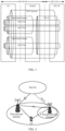
- the new QoS architecture is shown in FIG. 1 .
- an NG-CN establishes at least one Protocol Data Unit Session (PDU Session) for each UE, and the NG-CN and the UE allocate uplink and downlink data packets to corresponding QoS Flows (QFs) by using a packet filter of a Non-Access Stratum (NAS).
- PDU Session Protocol Data Unit Session
- QFs QoS Flows
- NAS Non-Access Stratum
- Each QF has its QoS profile (e.g., reliability, delay, rate, etc).
- the NG-RAN In the establishing process of each PDU session, the NG-RAN establishes at least one Data Radio Bearer (DRB) for each UE, and the NG-RAN and the UE will allocate the uplink and downlink QFs to the corresponding DRBs by using the mapping of the Access Stratum (AS), where each DRB has its own Data packet forwarding mode.
- DRB Data Radio Bearer
- the NG-RAN maps data packets belonging to different PDU sessions to different DRBs. Therefore, during the establishment of each PDU session, the NG-RAN establishes at least one default DRB for the currently established PDU session, and whether to establish a dedicated DRB is determined by the NG-RAN. For downlink, the NG-RAN determines the mapping relationship between QFs and DRBs based on an QF Identity (QF ID) of a data packet transmitted on an NG User Plane (NG-U) between the NG-RAN and the NG-CN and a QoS profile corresponding to the QF ID.
- QF ID QF Identity
- NG-U NG User Plane
- the UE For uplink, the UE sends the uplink data packet to the NG-RAN via the radio interface (Uu), where the uplink data packet is identified by the QF ID and carried on the corresponding DRB. Further, the NG-RAN has at least two methods for controlling the mapping between the QF uplink data packets and the DRBs, that is, a Reflective mapping method and an Explicit Configuration method. If an uplink data packet does not have the relevant information required by the two methods, the UE can map the uplink data packet to the default DRB of the PDU session to which the uplink data packet belongs for transmission.
- Uu radio interface
- the NG-RAN has at least two methods for controlling the mapping between the QF uplink data packets and the DRBs, that is, a Reflective mapping method and an Explicit Configuration method. If an uplink data packet does not have the relevant information required by the two methods, the UE can map the uplink data packet to the default DRB of the PDU session to which the uplink data packet belongs for transmission
- FIG. 2 shows a system architecture form called Dual Connectivity (DC).
- the current serving base station (referred to as a first network element) of the UE in the NG-RAN may select an appropriate base station (for example, quality of a radio channel satisfies a certain threshold) for the UE and add it for the UE (the base station added for the UE is referred to as a second network element), so that the two base stations can jointly provide radio resources for the UE for user plane data transmissions.
- an appropriate base station for example, quality of a radio channel satisfies a certain threshold
- an NG Control Plane (NG-C) interface is established between the first network element and the NG-CN for the UE, an NG-U interface is at most established between the second network element and the NG-CN for the UE, and the first network element and the second network element are connected through an ideal or non-ideal interface (referred to as an Xn interface).
- the first network element and the second network element may provide the same radio access technology (RAT) or different RATs and independently perform scheduling for the UE.
- RAT radio access technology
- FIG. 3 shows two bearer types when the complete Layer 2 (L2) protocol stack is located at the same base station.
- L2 Layer 2
- FIGS. 3b and 3c show two bearer types when the L2 protocol stack is located in two base stations.
- Xn-U user plane
- the L2 protocol stack includes a Packet Data Convergence Protocol (PDCP) sublayer, a Radio Link Control (RLC) sublayer, a Medium Access Control (MAC) sublayer, and a new AS sublayer for mapping QF and DRB.
- PDCP Packet Data Convergence Protocol
- RLC Radio Link Control
- MAC Medium Access Control
- new AS sublayer for mapping QF and DRB.
- MCG Master Cell Group
- SCG Secondary Cell Group
- two sets of RLC sublayer and MAC sublayer are configured for the bearers, and the two sets of RLC sublayer and MAC sublayer are independent and located in two base stations.
- the bearer configured with only the RLC sublayer and the MAC sublayer on the second network element in FIG. 3b is referred to as an MCG split bearer
- the bearer configured with only the RLC sublayer and the MAC sublayer on the first network element in FIG. 3c is referred to as an SCG split bearer.
- the reference EP 2836012 A1 discloses a method, in a radio communication system, for setup or modification of data flows between user equipment (UE) in dual connectivity with a primary node and a secondary node of the system.
- the reference EP 3026958 A1 discloses a method and an eNB for coordinated multi-stream transmission of data, which relate to mobile communication systems.
- embodiments of the present application provide a method and a device for configuring a new quality of service architecture in a dual-connectivity system.
- a method for configuring a new quality of service architecture in a dual-connectivity system includes the following steps.
- a first network element makes an offloading decision.
- the offloading decision includes at least an offloading granularity, an offloading object and an offloading bearer type.
- the first network element sends a control plane message to the second network element.
- the control plane message is used for requesting the second network element to perform admission decision and resource configuration of offloading resources, and carries offloading resource information which includes offloading object information and offloading bear type information.
- the offloading granularity includes one of the following: offloading all the quality of service flow (QFs) in the PDU session to a second network element; offloading part of the QFs in the PDU session to a second network element; or offloading part of data packets in all or part of QFs in the PDU session to a second network element.
- QFs quality of service flow
- the offloading object is one of the following: all QFs in the PDU session; part of QFs in the PDU session; or part of data packets in all or part of QFs in the PDU session.
- the offloading bear type includes one or any combination of the following: a secondary cell group (SCG) bearer; a SCG split bearer; and a master cell group (MCG) split bearer.
- SCG secondary cell group
- MCG master cell group
- the method further includes the steps described below.
- the first network element performs radio resource management, and determines whether the PDU session needs to be offloaded.
- the offloading object information includes at least a QF ID of a QF offloaded to the second network element and a QoS configuration profile corresponding to the QF ID.
- the offloading resource information further includes radio resource traffic information corresponding to the offloading object.
- the offloading resource information includes one or a combination of the following:
- the information of the PDU session includes at least one or a combination of the following:
- the offloading resource information further includes one or a combination of the following:
- the offloading resource information further includes a second indication for suggesting the second network element to accept a downlink data packet forwarded by the first network element.
- the offloading resource information further includes one or a combination of the following:
- the offloading resource information includes information of a tunnel port address allocated by the first network element on the Xn-U interface for the offloading bearer.
- the method further includes: receiving a response message from the second network element, where the response message carries radio resource configuration information made by the second network element for the UE; and generating RRC signaling for the UE and sending the RRC signaling to the UE, where the RRC signaling includes at least the radio resource configuration information made by the second network element for the UE.
- the method further includes: receiving an acknowledgement message from the UE, where the acknowledgement message is used for indicating that the UE successfully applies the radio resource configuration made by a second network element for the UE; and sending a control plane acknowledgement message to the second network element, where the control plane acknowledgement message is used for indicating that the UE successfully applies the radio resource configuration made by the second network element for the UE.
- control plane acknowledgement message further includes: information of the tunnel port address of the Xn-U interface allocated by the first network element for the SCG split bearer.
- the method further includes: after receiving the response message from the second network element, sending an Xn-C interface message to the second network element, where the Xn-C interface message carries information of the tunnel port address allocated for the SCG split bearer by the first network element at an Xn-U interface.
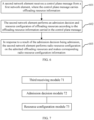
- a device for configuring a new quality of service architecture in a dual-connectivity system includes a decision module and a first sending module.
- the decision module is configured to make an offloading decision when a Protocol Data Unit (PDU) session of a User Equipment (UE) needs to be offloaded, where the offloading decision includes at least an offloading granularity, an offloading object, and an offloading bear type.
- PDU Protocol Data Unit
- UE User Equipment
- the first sending module is configured to send a control plane message to a second network element according to the offloading decision, where the control plane message is used for requesting the second network element to perform an admission decision and resource configuration of offloading resources.
- the control plane message carries offloading resource information, which includes offloading object information and offloading bear type information.
- the offloading granularity includes one of the following: offloading all of quality of service flow QFs in the PDU session to the second network element; offloading part of the QFs in the PDU session to a second network element; or offloading part of data packets in all or part of QFs in the PDU session to a second network element.
- the offloading object is one of the following: all QFs in the PDU session; part of QFs in the PDU session; or part of data packets in all or part of QFs in the PDU session.
- the offloading bear type includes one or any combination of the following: a secondary cell group (SCG) bearer; an SCG split bearer; and a master cell group (MCG) split bearer.
- SCG secondary cell group
- MCG master cell group
- the decision module is configured to perform radio resource management according to one or two of the current radio signal condition and the network load condition, and determine whether the PDU session needs to be offloaded.
- the offloading object information includes at least: a QF ID of a QF offloaded to the second network element and a QoS configuration profile corresponding to the QF ID.
- the offloading resource information further includes: radio resource traffic information corresponding to the offloading object.
- the offloading resource information includes one or a combination of the following:
- the information of the PDU session at least includes one or a combination of the following:
- the offloading resource information further includes one or a combination of the following:
- the offloading resource information further includes: a second indication used for suggesting the second network element to accept the downlink data packet forwarded by the first network element.
- the offloading resource information further includes one or a combination of the following:
- the offloading resource information further includes information of a tunnel port address allocated by the first network element on the Xn-U interface for the offloading bearer.
- the device further includes a first receiving module and a second sending module.
- the first receiving module is configured to receive a response message from the second network element.
- the response message carries radio resource configuration information made by the second network element for the UE.
- the second sending module is configured to generate RRC signaling for the UE and send the RRC signaling to the UE, where the RRC signaling includes at least the radio resource configuration information made by the second network element for the UE.
- the device further includes: a second receiving module configured to receive an acknowledgement message from the UE.
- the acknowledgement message indicates that the UE successfully applies radio resource configuration made by the second network element for the UE.
- the first sending module is further configured to send a control plane acknowledgement message to the second network element, where the control plane acknowledgement message indicates that the UE successfully applies the radio resource configuration made by the second network element for the UE.
- control plane acknowledgement message further includes information of a tunnel port address allocated by the first network element for the SCG split bearer at an Xn-U interface.
- the device further includes: the first sending module.
- the first sending module is further configured to send an Xn-C interface message to the second network element, where the Xn-C interface message carries the information of the tunnel port address allocated by the first network element for the SCG split bearer at an Xn-U interface.
- a method for configuring a new quality of service architecture in a dual-connectivity system includes the steps described.
- a second network element receives a control plane message from a first network element.
- the control plane message carries offloading resource information.
- the second network element performs an admission decision of the offloading resource.
- the second network element performs radio resource configuration for the admitted offloading resources and obtains corresponding radio resource configuration information
- the offloading resource information comprises: offloading object information and offloading bearer type information,wherein the offloading granularity comprises one of the following: offloading all of quality of service flows, QFs, in the PDU session to the second network element;offloading part of the QFs in the PDU session to the second network element; oroffloading part of data packets in all or part of the QFs in the PDU session to the second network element,wherein the offloading object is one of the following:all of QFs in the PDU session;part of the QFs in the PDU session; orpart of data packets in all or part of the QFs in the PDU session,wherein the offloading bearer type comprises one or any combination of the following:a secondary cell group, SCG, bearer;an SCG split bearer; ora master cell group, MCG, split bearer
- the radio resource configuration information includes at least: mapping relationship information between the offloading object and an offloading bearer; configuration information of a radio protocol stack of the offloading bearer on the second network element side; and information of a transport layer address and a tunnel port address allocated for the offloading object at an NG-U interface.
- the offloading resource information includes a first indication for notifying the second network element to establish a default data radio bearer for the PDU session.
- the radio resource configuration includes: establishing a default data radio bearer for the PDU session according to the first indication.
- the radio resource configuration information includes: a default indication for identifying the default data radio bearer.
- the radio resource configuration information includes division result information of radio resource traffic.
- the radio resource configuration information includes information of a tunnel port address allocated for the SCG split bearer at the Xn-U interface.
- the radio resource configuration information includes at least:
- the method further includes: in response to determining to accept a forwarded data packet suggested in the second indication, the radio resource configuration information includes information of the tunnel port address at the Xn-U interface for receiving the forwarded data packet, where the information is allocated by the second network element.
- a device for configuring a new quality of service architecture in a dual-connectivity system includes a third receiving module, an admission decision module and a resource configuration module.
- the third receiving module is configured to receive a control plane message from a first network element, where the control plane message carries offloading resource information.
- the admission decision module is configured such that a second network element performs an admission decision of the offloading resource according to the offloading resource information carried by the control plane message.
- the resource configuration module is configured such that when a result of the admission decision is admission, the second network element performs radio resource configuration for the admitted offloading resources and obtains corresponding radio resource configuration information
- the offloading resource information comprises: offloading object information and offloading bearer type information,wherein the offloading granularity comprises one of the following: offloading all of quality of service flows, QFs, in the PDU session to the second network element;offloading part of the QFs in the PDU session to the second network element; oroffloading part of data packets in all or part of the QFs in the PDU session to the second network element,wherein the offloading object is one of the following:all of QFs in the PDU session;part of the QFs in the PDU session; orpart of data packets in all or part of the QFs in the PDU session,wherein the offloading bearer type comprises one or any combination of the following:a secondary cell group, SCG, bearer;an SCG split bearer; ora master
- the radio resource configuration information includes at least:
- the offloading resource information includes a first indication for notifying the second network element to establish a default data radio bearer for the PDU session.
- the resource configuration module is configured to establish a default data radio bearer for the PDU session according to the first indication; and the radio resource configuration information includes: a default indication for identifying for the default data radio bearer.
- the radio resource configuration information includes division result information of radio resource traffic, made by the second network element.
- the radio resource configuration information includes information of a tunnel port address allocated for the SCG split bearer at the Xn-U interface.
- the radio resource configuration information includes at least:
- the resource configuration module is further configured to cause, in response to determining to accept a forwarded data packet suggested in the second indication, the radio resource configuration information to include information of a tunnel port address for receiving the forwarded data packet, where the tunnel port address is at the Xn-U interface and allocated by the second network element.
- a not claimed device for configuring a new quality of service architecture in a dual-connectivity system includes a memory and a processor.
- the memory stores a configuration program.
- the processor is configured to execute the configuration programs to perform the following operations.
- a not claimed computer-readable storage medium stores a configuration program which, when executed by a processor, performs the steps of the above-described method for configuring a new quality of service architecture in a dual-connectivity system.
- a device for configuring a new quality of service architecture in a dual-connectivity system includes a memory and a processor.
- the memory stores a configuration program.
- the processor is configured to perform the configuration programs to perform the following operations:
- a computer-readable storage medium stores a configuration program which, when executed by a processor, performs the steps of the above-described method for configuring a new quality of service architecture in a dual-connectivity system.
- two network elements can effectively perform reasonable configuration on the user plane bearer of the UE, the establishment of the user plane bearer of the dual-connectivity system under a new QoS (quality of service) architecture is achieved, and the data transmission can be performed on the user plane bearer, so that the uplink and downlink data can be efficiently and correctly transmitted on both a radio interface and a wired interface, the transmission performance requirement of the user plane data in a 5G system is met, and the user experience is improved.
- QoS quality of service
- a method for configuring a new quality of service architecture in a dual-connectivity system includes the steps described below.
- a first network element makes an offloading decision when a Protocol Data Unit (PDU) session of a User Equipment (UE) needs to be offloaded.
- the offloading decision includes at least an offloading granularity, an offloading object, and an offloading bear type.
- the first network element sends a control plane message to a second network element.
- the control plane message is used for requesting the second network element to perform an admission decision and resource configuration of offloading resources, and carries offloading resource information.
- the offloading resource information includes offloading object information and offloading bear type information.
- the configuration method in the present embodiment may be performed by the first network element.
- the first network element refers to a base station or other similar network elements that currently provide a communication service for the UE.
- the first network element and the second network element can effectively perform reasonable configuration on the user plane bearer of the UE, the establishment of the user plane bearer of the dual-connectivity system under a new QoS architecture is achieved, and the data transmission can be performed on the user plane bearer, so that the uplink and downlink data can be efficiently and correctly transmitted on a radio interface and a wired interface, the transmission performance requirement of the user plane data in a 5G system is met, and the use experience of a user is improved.
- the offloading resource refers to a resource that is offloaded to the second network element by the first network element, and the offloading resource may be an offloading object, an offloading bearer, and the like.
- the offloading decision may also be a decision made by the first network element according to a request of the second network element.
- the offloading granularity includes, but is not limited to, one of the following.
- the offloading object is one of the following:
- the offloading object when “a” is selected as the offloading granularity, the offloading object is all QFs in the PDU session.
- the offloading object refers to QFs in the PDU session which are to be offloaded.
- the offloading bear type includes one or any combination of the following: an SCG bearer; an SCG split bearer; or an MCG split bearer.
- the offloading bear type may be an SCG bearer and/or an SCG split bearer; when "c" is selected as the offloading granularity, the offloading bear type may be an MCG split bearer.
- the method may further include: according to one or two of the current radio signal condition and the network load condition, radio resource management is performed, and whether the PDU session needs to be offloaded (that is, whether it needs to cooperate with a second network element to provide DC service for the UE) is determined.
- the above method of the present embodiment may not be performed when it is determined that the PDU session does not need to be offloaded.
- the offloading object information includes at least an identify of the offloading object (that is, QF ID) and a QoS profile corresponding to the QF ID.
- the offloading resource information may further include radio resource traffic information (e.g., bit rate, throughput, etc.) corresponding to the offloading object.
- the offloading resource information further includes one or a combination of the following:
- the information of the PDU session includes at least one or a combination of the following:
- the offloading resource information further includes one or a combination of: 1) information of a transport layer address and tunnel port address information, allocated by an NG-CN, of the offloading object on a next generation user plane (NG-U) interface between a next generation Radio Access Network and the NG-CN; 2) a first indication for notifying the second network element to establish a default data radio bearer for the PDU session; and 3) access stratum security related information.
- NG-U next generation user plane
- the offloading resource information may further include a second indication used for suggesting the second network element to accept the downlink data packet forwarded by the first network element.
- the offloading resource information further includes one or a combination of: 1) the configuration information of a radio protocol stack of an offloading bearer on the first network element side; and 2) the mapping relationship information of an offloading bearer at the first network element side and the corresponding QF.
- the offloading resource information includes tunnel port address information allocated by the first network element on the Xn-U interface for the offloading bearer.
- the method further includes: receiving a response message from the second network element, where the response message carries radio resource configuration information made by the second network element for the UE; and generating RRC signaling for the UE and sending the RRC signaling to the UE, where the RRC signaling includes at least the radio resource configuration information made by the second network element for the UE.
- the RRC signaling may also include radio resource configuration information made by the first network element for the UE.
- the method further includes: receiving an acknowledgement message from the UE, where the acknowledgement message is used for indicating that the UE successfully applies the radio resource configuration made by the second network element for the UE; and sending a control plane acknowledgement message to the second network element, where the control plane acknowledgement message is used for indicating that the UE successfully applies the radio resource configuration performed by the second network element for the UE.
- control plane acknowledgement message may further include tunnel port address information allocated by the first network element for the SCG split bearer at an Xn-U interface.
- the method may further include: after receiving the response message from the second network element, sending an Xn-C interface message to the second network element, where the Xn-C interface message carries the tunnel port address information allocated by the first network element for the SCG split bearer at an Xn-U interface.
- the tunnel port address information allocated by the first network element for the SCG split bearer on the Xn-U interface can be carried by a new Xn-C interface message, and the first network element sends the new Xn-C interface message to the second network element after receiving the response message sent by the second network element for the control plane request message.
- a device for configuring a new quality of service architecture in a dual-connectivity system includes a decision module 51 and a first sending module 52.
- the decision module 51 is configured to make an offloading decision when a Protocol Data Unit (PDU) session of a User Equipment (UE) needs to be offloaded.
- the offloading decision includes at least an offloading granularity, an offloading object, and an offloading bear type.
- the first sending module 52 is configured to send a control plane message to a second network element according to the offloading decision.
- the control plane message is used for requesting the second network element to perform an admission decision and resource configuration of offloading resources, and carries offloading resource information.
- the offloading resource information includes offloading object information and offloading bear type information.
- the offloading granularity includes one of the following:
- the offloading object is one of the following:
- the offloading bear type includes one or any combination of the following:
- the decision module 51 is configured to perform radio resource management according to one or two of the current radio signal condition and the network load condition, and determine whether the PDU session needs to be offloaded.
- the offloading object information includes at least: the QF ID of the QF offloaded to the second network element and the QoS configuration profile corresponding to the QF ID.
- the offloading resource information further includes: radio resource traffic information corresponding to the offloading object.
- the offloading resource information further includes one or a combination of the following: information of the PDU session; and access stratum security related information.
- the information of the PDU session includes at least one or a combination of the following: an identity of the PDU session; an aggregated maximum bit rate of the PDU session; and a transport layer address and a tunnel port address allocated by the NG-CN for the PDU session.
- the offloading resource information further includes one or a combination of: transport layer address and tunnel port address information allocated by an NG-CN for the offloading object on an NG-U interface between a next generation Radio Access Network and the NG-CN; a first indication for notifying the second network element to establish a default data radio bearer for the PDU session; and access stratum security related information.
- the offloading resource information further includes a second indication used for suggesting the second network element to accept the downlink data packet forwarded by the first network element.
- the offloading resource information further includes one or a combination of: configuration information of a radio protocol stack of an offloading bearer on a first network element side; and mapping relationship information between the offloading bearer on the first network element side and a corresponding QF.
- the offloading resource information further includes tunnel port address information allocated by the first network element for the offloading bearer at the Xn-U interface.
- the device further includes a first receiving module 53 and a second sending module 54.
- the first receiving module 53 is configured to receive a response message from the second network element, where the response message carries radio resource configuration information made by the second network element for the UE.
- the second sending module 54 is configured to generate RRC signaling for the UE and send the RRC signaling to the UE, where the RRC signaling includes at least radio resource configuration information made by the second network element for the UE.
- the device further includes a second receiving module 55, which is configured to receive an acknowledgement message from the UE.
- the acknowledgement message is used for indicating that the UE successfully applies the radio resource configuration made by the second network element for the UE.
- the first sending module 52 may be further configured to send a control plane acknowledgement information to the second network element, where the control plane acknowledgement information is used for indicating that the UE successfully applies the radio resource configuration made by the second network element for the UE.
- control plane acknowledgement message further includes tunnel port address information allocated by the first network element for the SCG split bearer at an Xn-U interface.
- the first sending module 52 is configured to send an Xn-C interface message to the second network element, where the Xn-C interface message carries the tunnel port address information allocated by the first network element for the SCG split bearer at the Xn-U interface.
- the configuration device in the present embodiment may be disposed on the first network element or other similar devices to perform the above functions, or the configuration device in the present embodiment may be implemented directly through the first network element or other similar devices.
- the decision module 51, the first sending module 52, the first receiving module 53, the second sending module 54, and the second receiving module 55 can be implemented by means of software, hardware, or a combination thereof.
- the first sending module 52, the first receiving module 53, the second sending module 54, and the second receiving module 55 may be implemented by a processor of the first network element controlling a communication unit thereof, and the decision module 51 may be implemented by the processor of the first network element. No limitation is made herein.
- a device for configuring a new quality of service architecture in a dual-connectivity system includes a memory and a processor.
- the memory stores a configuration program.
- the processor is configured to execute the configuration program to perform the following operations.
- An offloading decision is made when a Protocol Data Unit (PDU) session of a User Equipment (UE) needs to be offloaded.
- the offloading decision includes at least an offloading granularity, an offloading object, and an offloading bear type.
- a control plane message is sent to a second network element, where the control plane message is used for requesting the second network element to perform an admission decision and resource configuration of offloading resources.
- the control plane message carries offloading resource information, which includes offloading object information and offloading bear type information.
- the configuration device in the present embodiment may be disposed in the first network element or other similar devices to perform the above functions, or the configuration device in the present embodiment may be implemented directly through the first network element or other similar devices.
- a method for configuring a new quality of service architecture in a dual-connectivity system includes the steps described below.
- a second network element receives a control plane message from a first network element.
- the control plane message carries offloading resource information.
- step 602 according to the offloading resource information carried by the control plane message, the second network element performs an admission decision of the offloading resource.
- step 603 when a result of the admission decision is admission, the second network element performs radio resource configuration for the admitted offloading resources and obtains corresponding radio resource configuration information.
- the configuration method of the present embodiment may be performed by the second network element.
- the user plane bearer between the first network element and the second network element can effectively and reasonably configured for the UE, the establishment of the user plane bearer of the dual-connectivity system under a new QoS architecture is achieved, and the data transmission can be performed on the user plane bearer, so that the uplink and downlink data can be efficiently and correctly transmitted on a radio interface and a wired interface, the transmission performance requirement of the user plane data in a 5G system is met, and the use experience of a user is improved.
- the second network element makes an admission decision according to the control plane message from the first network element, and performs radio resource configuration for the admitted offloading resources when admission is allowed.
- the admission decision refers to: if the current resource load condition of the second network element can satisfy the request corresponding to the offloading resource (that is, QF), the second network element decides to admit the request of the first network element; otherwise, the decision is rejection.
- the second network element decides to admit, the second network element performs radio resource configuration and obtains corresponding radio resource configuration information.
- the radio resource configuration information includes at least:
- the second network element establishes a default DRB for the PDU session, and the radio resource configuration information needs to identify which offloading bearer is the default DRB. That is, the offloading resource information includes a first indication for notifying the second network element to establish a default data radio bearer for the PDU session.
- the radio resource configuration includes: establishing a default data radio bearer for the PDU session according to the first indication; and the radio resource configuration information includes: a default indication for identifying the default data radio bearer.
- the radio resource configuration information includes division result information of radio resource traffic.
- the radio resource configuration information includes tunnel port address information allocated by the second network element for the SCG split bearer at an Xn-U interface.
- the radio resource configuration information includes at least: configuration information of a radio protocol stack (RLC sublayer, MAC sublayer and physical layer) of an offloading bearer on the second network element side; and tunnel port address information allocated by the second network element for the offloading bearer at the Xn-U interface.
- RLC sublayer, MAC sublayer and physical layer radio protocol stack
- the method further includes: in response to determining to accept a forwarded data packet suggested in the second indication, the radio resource configuration information includes tunnel port address information of the Xn-U interface for receiving the forwarded data packet, where the tunnel port address is allocated by the second network element.
- a device for configuring a new quality of service architecture in a dual-connectivity system includes a third receiving module 71, an admission decision module 72 and a resource configuration module 73.
- the third receiving module 71 is configured to receive a control plane message from a first network element.
- the control plane message carries offloading resource information.
- the admission decision module 72 is configured such that a second network element performs an admission decision of the offloading resources according to the offloading resource information carried by the control plane message.
- the resource configuration module 73 is configured such that when the result of the admission decision is admission, the second network element performs radio resource configuration for the admitted offloading resources and obtains corresponding radio resource configuration information.
- the radio resource configuration information includes at least: mapping relationship information between the offloading object and an offloading bearer; configuration information of a radio protocol stack of the offloading bearer on a second network element side; and transport layer address and tunnel port address information allocated by the second network element for the offloading object at an NG-U interface.
- the offloading resource information includes a first indication for notifying the second network element to establish a default data radio bearer for the PDU session.
- the resource configuration module 73 is configured to establish a default data radio bearer for the PDU session according to the first indication.
- the radio resource configuration information includes: a default indication for identifying for the default data radio bearer.
- the radio resource configuration information includes division result information of radio resource traffic made by the second network element.
- the radio resource configuration information includes tunnel port address information allocated by the second network element for the SCG split bearer at an Xn-U interface.
- the radio resource configuration information includes at least: configuration information of a radio protocol stack of an offloading bearer on a second network element side; and the tunnel port address information allocated by the second network element for the offloading bearer at the Xn-U interface.
- the resource configuration module 73 is further configured to cause, in response to determining to accept a forwarded data packet suggested in the second indication, the radio resource configuration information to include tunnel port address information allocated by the second network element at the Xn-U interface for receiving the forwarded packet.
- the configuration device in the present embodiment may be disposed in the second network element or other similar devices to perform the above functions, or the configuration device in the present embodiment may be implemented directly through the second network element or other similar devices.
- the third receiving module 71, the admission decision module 72, and the resource configuration module 73 may respectively be implemented by software, hardware, or a combination thereof.
- the third receiving module 71 may be implemented by a processor of the second network element controlling a communication unit thereof, and the admission decision module 72 and the resource configuration module 73 may be implemented by the processor of the second network element. No limitation is made herein.
- a device for configuring a new quality of service architecture in a dual-connectivity system includes a memory and a processor.
- the memory stores a configuration program.
- the processor is configured to execute the configuration program to perform the following operations.
- a control plane message is received from a first network element, where the control plane message carries offloading resource information.
- An admission decision of the offloading resource is performed according to the offloading resource information carried by the control plane message;
- the radio resource configuration is performed for the admitted offloading resources and the corresponding radio resource configuration information is obtained.
- the configuration device in the present embodiment may be disposed in the second network element or other similar devices to perform the above functions, or the configuration device in the present embodiment may be implemented directly through the second network element or other similar devices.
- the above embodiments may occur during the establishment of the PDU session, during the modification of the PDU session, or in the case where control plane signaling procedure related to the PDU session does not occur at the NG interface.
- the configuration process of the above embodiments may occur during the addition of the second network element or during the modification of the second network element.
- the first network element side and the second network element side may establish a default DRB for the UE (the default DRB can only be established on the first network element side, or established on the first network element side or the second network element side by network configuration), or two default DRBs (one is established on the first network element side and the other is established on the second network element side).
- the UE maps the uplink data packet on the default data radio bearer for transmission. If the PDU session establishes a default data radio bearer on each of the two network element sides, the UE may map the uplink data packet on a corresponding default DRB for transmission according to radio resource configuration information (that is, whether the uplink data packet belongs to an offloading object) indicated by the first network element.
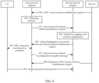
- a first network element receives a PDU session establishment request message indicated by the NG-CN when the first network element is providing communication service for a UE.
- the first network element performs radio resource management and may decide to offload the PDU session to a second network element for transmission.
- an implementation process of the present embodiment may include steps described below.
- step 801 the UE accesses the first network element and is in a Radio Resource Control Connected (RRC_Connected) state, the first network element receives a first control plane message (that is, a PDU session resource establishment request) from the NG-CN via the NG-C interface, and the first control plane message indicates that the network needs to establish a new PDU session for the UE.
- RRC_Connected Radio Resource Control Connected
- the first control plane message includes at least information of the PDU session and related information of QFs in the PDU session.
- the information of the PDU session includes at least an identity of the PDU session; an aggregated maximum bit rate and a transport layer address and a tunnel port address allocated by the NG-CN for the PDU session.
- the information related to the QFs may include at least identities of the QFs and a QoS profile.
- step 802 the first network element makes an offloading decision.
- the first network element performs radio resource management according to information carried by the first control plane message and other obtained information (such as a measurement report result, load information, and the like), and if the first network element determines that the PDU session needs to be offloaded (that is, a DC mode is applied), the first network element proceeds to execute an offloading decision.
- the offloading decision may include at least an offloading granularity, an offloading object, and an offloading bear type.
- the offloading granularity includes, but not limited to, one of the following:
- the offloading object refers to the offloaded part of QFs in the PDU session.
- the offloading object refers to all QFs in the PDU session.
- the offloading bear type may include: an SCG bearer, an SCG split bearer, an MCG split bearer, and the like.
- the offloading bear type when a or b is selected as the offloading granularity, the offloading bear type may be the SCG bearer and/or the SCG split bearer; when c is selected as the offloading granularity, the offloading bear type may be the MCG split bearer.
- a or b is selected as the offloading granularity
- the corresponding offloading bear type is the SCG bearer and/or the SCG split bearer
- the offloading object is offloaded part of QFs in the PDU session or all QFs in the PDU session.
- the first network element sends a third control plane message (such as a second network element addition request, a second network element modification request, and the like) to the second network element through the Xn interface according to the offloading decision, where the third control plane message is used for requesting the second network element to admit the offloading resource.
- the third control plane message may occur in a second network element addition procedure (that is, corresponding to the second network element addition request information), or in a second network element modification procedure (that is, corresponding to the second network element modification request information).
- the third control plane message carries the offloading resource information, and the offloading resource information includes at least offloading object information and offloading bear type information.
- the offloading resource information includes at least offloading object information and offloading bear type information.
- a or b is selected as the offloading granularity
- the corresponding offloading bear type is the SCG bearer and/or the SCG split bearer
- the offloading object is the offloaded part of QFs in the PDU session or all QFs in the PDU session.
- the offloading object information in the offloading resource information includes QF IDs of all or part of QFs offloaded to the second network element and QoS profiles thereof.
- the offloading bear type information includes information indicating that the current offloading bearer is the SCG bearer and/or the SCG split bearer.
- the offloading resource information may further include information of the PDU session in step 801. If b is selected as the offloading granularity, the offloading resource information may further include the transport layer address and tunnel port address information of the QFs allocated at the NG-U interface. In the two options, the offloading resource information may further include a first indication and security-related information. The first indication is used for notifying the second network element to establish a default data radio bearer, and the security-related information may include: a key derived by the first network element for the safety of the radio resources on the second network element side.
- the offloading resource information may further include radio resource traffic information provided by the first network element for offloading QFs.
- the radio resource traffic information may be represented as a traffic bit value or a proportion value of the divided by the first network element for DC, or total traffic value information of the UE.
- step 804 the second network element performs admission, mapping and resource configuration
- the second network element after receiving the third control plane message, the second network element first determines whether to admit the flows according to offloading resource information carried by the third control plane message.
- the second network element may admit part or all of QFs indicated by the offloading object information in the offloading resource information. As long as the radio resource condition of the second network element can satisfy the request of at least one QF, the second network element allows admission; otherwise, the second network element does not allow admission.
- the second network element For the offloading resources the second network element decides to admit, the second network element performs radio resource configuration and obtains corresponding SCG radio resource configuration information.
- the SCG radio resource configuration information includes at least mapping relationship information between the QF and the SCG bearer and/or the SCG split bearer, protocol stack configuration information of the SCG bearer and/or the SCG split bearer in the L2 and physical layer of the second network element, and transport layer address and port address information of an NG-U data transmission tunnel allocated to the QF by the second network element.
- the second network element needs to identify, in the SCG radio resource configuration information, which SCG bearer or SCG split bearer is the default data radio bearer. That is, the SCG radio resource configuration information may further include an identifier for indicating which offloading bearer is the default data radio bearer.
- the second network element needs to make a traffic dividing not exceeding the radio resource traffic information indicated in the third control plane message, and the result of the traffic dividing is included in the SCG radio resource configuration information. It is to be noted that, for the SCG bearer, the time for the second network element to establish each SCG bearer on the radio interface is determined by the second network element. If the SCG bearer is not established in the current process, the radio protocol stack configuration information of the SCG bearer may not be included in the SCG radio resource configuration information.
- the second network element replies a response message (such as a second network element addition request acknowledgement message or a second network element modification request acknowledgement message) for the third control plane message to the first network element, where the response message includes the SCG radio resource configuration information.
- a response message such as a second network element addition request acknowledgement message or a second network element modification request acknowledgement message
- the response message may further include an identity of the QF rejected by the second network element.
- step 806 an RRC connection reconfiguration procedure is performed between the first network element and the UE;
- the first network element performs radio resource configuration for the SCG split bearer configured by the second network element according to the information carried by the response message, the SCG split bearer configured by the second network element, the mapping relationship between the admitted QF and the SCG split bearer, the QoS profile of the QF of each SCG split bearer, and the traffic dividing result indicated by the second network element, and obtains corresponding MCG radio resource configuration information.
- the first network element also needs to allocate a port address of a tunnel for transmitting offloading data on the Xn interface for each SCG split bearer.
- the first network element needs to decide an operation for the QF, and the operation includes but is not limited to releasing the QF.
- the first network element combines the MCG radio resource configuration information (if any) and the SCG radio resource configuration information, generates RRC control plane request signaling (such as RRC Connection Reconfiguration), and sends the RRC control plane request signaling to the UE through a radio interface between the first network element and the UE. If the resource configuration indicated by the RRC control plane signaling is successfully configured by the UE, the UE replies corresponding RRC control plane acknowledgement signaling (that is, RRC Connection Reconfiguration Complete).
- RRC control plane request signaling such as RRC Connection Reconfiguration
- step 807 after receiving the RRC control plane acknowledgement signaling replied by the UE, the first network element sends an Xn interface message (that is, a second network element reconfiguration complete message) to the second network element, where the Xn interface information is used for indicating to the second network element that the UE successfully applies the SCG radio resource configuration information.
- an Xn interface message that is, a second network element reconfiguration complete message
- the Xn interface message may further include port address information of a tunnel allocated by the first network element for each SCG split bearer at the Xn interface.
- the address information of the tunnel may also be carried by a new Xn interface message, and after receiving the response message from the second network element, the first network element sends the new Xn interface message to the second network element.
- the first network element sends a response message (such as a PDU session resource establishment request response) to the NG-CN for the first control plane message, where the response message includes at least address information and port information of NG-U data transmission allocated by the NG-RAN for the admitted QFs, and the identities of the rejected QFs (if any).
- a response message such as a PDU session resource establishment request response
- step 809 uplink data packet transmission is performed between the UE and the second network element.
- the UE For the PDU session, if the UE needs to transmit an uplink data packet and the uplink data packet does not have any indication information for indicating which bearer the uplink data packet corresponds to, if a default data radio bearer is established on only one of the first network element side and the second network element side for the PDU session, the UE maps the uplink data packet on the default data radio bearer for transmission. If both the first network element and the second network element establish the default data radio bearers for the PDU session, the UE may map the uplink data packet on the corresponding default data radio bearer for transmission according to radio resource configuration information (that is, whether the uplink data packet belongs to the offloading object) indicated by the first network element.
- radio resource configuration information that is, whether the uplink data packet belongs to the offloading object
- the first network element performs radio resource management in the process of providing communication service for the UE.
- the first network element determines to cooperate with the second network element to configure an architecture in which the user plane bearer mode is the MCG split bearing, and provides DC communication service for the UE.
- an implementation process of the present embodiment may include steps described below.
- step 901 for the UE in RRC_Connected, the first network element performs an offloading decision, and sends a first control plane message to the second network element through the Xn interface to request the second network element to provide radio resources for the indicated MCG split bearer, where the first control plane message carries offloading resource information;
- the first control plane message may occur during the establishment of the PDU session (that is, similar to step 801 and step 802 in example one, only the offloading bear type is selected to be the MCG split bearer), or during the modification of the PDU session (for example, the NG-CN adds a new QF for the PDU session), or when no change occurs on the NG-C interface.
- the first control plane message may occur in the second network element addition procedure or in the second network element modification procedure (for example, before step 901, the first network element and the second network element have collaboratively established at least one MCG split bearer for the UE).
- the offloading resource information carried by the first control plane message may include: offloading object information and offloading bear type information. Since the MCG split bearer needs to be configured currently, the offloading bear type information includes information indicating MCG split bearer.
- the offloading object information may include QF IDs of QFs in the MCG split bearer and QoS Profile information thereof and the radio resource traffic information allocated by the first network element for the MCG split bearer.
- the offloading resource information further includes: radio protocol stack configuration information made by the first network element for the MCG split bearer which needs to be configured currently on a first network element side, and tunnel port address information allocated by the first network element for the MCG split bearer on the Xn-U interface (if the uplink split is supported).
- step 902 the second network element performs admission and resource configuration
- the second network element firstly performs admission decision according to the radio resource requested by the first network element. If the second network element can accept the addition of at least one MCG split bearer, the second network element determines to accept the request of the first control plane message; otherwise, rejects the request.
- the second network element For the MCG split bearer whose admission decision result is admission, the second network element performs radio resource configuration and obtains corresponding MCG radio resource configuration information.
- the MCG radio resource configuration information includes at least protocol stack configuration information of the MCG split bearer in the L2 (that is, an RLC sublayer and an MAC sublayer) and a physical layer on the second network element side, and the tunnel port address information allocated for the MCG split bearer on an Xn-U interface by the second network element.
- the second network element includes the MCG radio resource configuration information in a response message with respect to the first control plane message (that is, a second network element addition request acknowledgement message or a second network element modification request acknowledgement message) and replies the response message to the first network element through an Xn interface.
- the response message may further include an identity of the MCG split bearer rejected by the second network element.
- step 904 an RRC connection reconfiguration procedure is performed between the first network element and the UE.
- the first network element can perform necessary radio resource configuration according to the MCG radio resource configuration information carried by the response message.
- the radio resource configuration includes the operations of adjusting the radio protocol stack configuration of the accepted MCG split bearer on the first network element side, obtaining the corresponding MCG radio resource configuration information and/or the MCG split bearer rejected by the second network element.
- the operation includes but is not limited to configuring the MCG split bearer to be an MCG bearer and obtaining corresponding MCG radio resource configuration information, or releasing the MCG split bearer (at this time, indicating a QF identity in the MCG split bearer to the NG-CN).
- the first network element may combine the current MCG radio resource configuration information with the SCG radio resource configuration information previously obtained from the second network element, generate RRC control plane request signaling, and send the RRC control-plane request signaling to the UE through the radio interface. If the UE successfully configures the resources indicated by the RRC control plane request signaling, the UE replies corresponding RRC control plane acknowledgement signaling to the first network element.
- step 905 after the first network element receives the RRC control plane acknowledgement signaling sent by the UE, the first network element sends an Xn interface message (for example, a second network element reconfiguration complete message) to the second network element, where the Xn interface message is used for indicating to the second network element that the UE successfully applies the SCG radio resource configuration information.
- an Xn interface message for example, a second network element reconfiguration complete message
- the default data radio bearer which may be an MCG bearer or an MCG split bearer, is established only on the first network element side. Therefore, if the UE needs to transmit an uplink data packet, and there is no indication information for indicating which bearer the uplink data packet corresponds to, the UE maps the uplink data packet on a default data radio bearer established on the radio interface between the UE and the first network element for transmission.
- a first network element performs a primary radio resource management, which includes a user plane bearer type used in the DC system. For example, the first network element may decide to change the type of a certain bearer.
- an implementation process of the present embodiment may include steps described below.
- step 1001 the first network element performs an offloading decision and makes a decision of changing a user plane bearer type.
- the DC system may have a user plane mode in which a part of QFs is mapped on one MCG bearer and another part of QFs is mapped on one SCG bearer.
- the first network element may make a decision of changing the user plane bearer type according to the varying radio resource condition of the network and/or the request of the second network element, and the decision may include but is not limited to: changing the MCG bearer to the SCG bearer (or vice versa), or changing the MCG bearer to the SCG split bearer (or vice versa), or changing the SCG bearer to the SCG split bearer (or vice versa).
- the bearer type change may further relate to specifically targeted QFs.
- the following are involved: whether all QFs in the MCG bearer are offloaded to the second network element and mapped to at least one SCG bearer or only part of QFs in the MCG bearer are offloaded to the second network element and mapped to at least one SCG bearer (while another part of QFs remains in the MCG bearer). That is, the decision of changing the user plane bearer type made by the first network element needs to include a specific offloading object.
- the first network element sends a second control plane message to the second network element through the Xn interface, where the second control plane message may be a second network element modification request message, and is used for requesting the second network element to admit the offloading resources indicated by the offloading resource information.
- the second control plane message may be a second network element modification request message, and is used for requesting the second network element to admit the offloading resources indicated by the offloading resource information.
- the second control plane message may include at least the offloading resource information, where the offloading resource information may include at least the offloading object information (for example, the QF ID and QoS profile thereof), and bearer type information (for example, SCG bearer type).
- the offloading resource information may include at least the offloading object information (for example, the QF ID and QoS profile thereof), and bearer type information (for example, SCG bearer type).
- the offloading resource information may further include a mapping relationship between the MCG bearer and the offloading object on the first network element side, and radio resource configuration information of the MCG bearer on the first network element side, where the part of content may be used as a reference for radio resource mapping and configuration by the second network element.
- the offloading resource information may further include: PDU session information to which the offloading object belongs, transport layer address and tunnel port address information allocated to the offloading object on the NG-U interface, and security related information such as a key derived by the first network element for radio resource security of the second network element side. If the first network element suggests to changing the bearer for DL Data Forwarding, the offloading resource information may further include a second indication, where the second indication is used for suggesting the second network element to perform DL Forwarding on the forwarded data packets from the first network element.
- the offloading resource information needs to further include a first indication, where the first indication is used for notifying a second network element to establish a default data radio bearer.
- the situation that the second network element needs to establish a default data radio bearer may be applicable to a scenario that the first network element determines to change the default data radio bearer originally established on the first network element side to be established on the second network element side, or may be applicable to a scenario that the first network element determines that each of the network element sides needs to establish the default data radio bearer.
- the second network element first determines whether there are enough radio resources to accept the request of at least one offloading object. If the radio resources are sufficient to accept the request of at least one offloading object, the second network element determines the mapping relationship of the accepted offloading object, performs radio resource configuration, and obtains corresponding SCG radio resource configuration information.
- the SCG radio resource configuration information includes at least mapping relationship information between the offloading object and the SCG bearer (which includes but is not limited to adding the offloading object to an originally established SCG bearer, and/or establishing at least one SCG bearer for the offloading object, and a mapping relationship between the newly established SCG bearer and the offloading object), protocol stack configuration information of L2 and a physical layer on the second network element side for the SCG bearer, and transport layer address and port address information of an NG-U data transmission tunnel allocated by the second network element for the offloading object.
- the SCG radio resource configuration information further needs to include tunnel port address information of an Xn-U forwarding tunnel allocated by the second network element for accepting the forwarding data packets.
- the second network element needs to identify, in the SCG radio resource configuration information, which SCG bearer is the default data radio bearer. That is, the SCG radio resource configuration information includes a default indication for identifying the default data radio bearer.
- the second network element replies a response message (such as a second network element modification request acknowledgment message) for the second control plane message to the first network element, where the response message includes the SCG radio resource configuration information.
- a response message such as a second network element modification request acknowledgment message
- the method may further include an identity (QF ID) of the offloading object rejected by the second network element.
- QF ID an identity of the offloading object rejected by the second network element.
- step 1005 an RRC connection reconfiguration procedure is performed between the first network element and the UE; Specifically, after receiving the response message, the first network element performs control plane and user plane operations. These operations are similar to those in example one, the difference is that the present embodiment does not include the configuration of the SCG split bearer, and the principles are the same and are not described again.
- the present application further provides a computer-readable storage medium, which stores a configuration program.
- the configuration program when executed by a processor, performs the steps of the method for configuring a new quality of service architecture in a dual-connectivity system which is described in the embodiment one.
- the present application further provides a computer-readable storage medium, which stored a configuration program.
- the configuration program when executed by a processor, performs the steps of the method for configuring a new quality of service architecture in a dual-connectivity system which is described in the embodiment four.
- embodiments of the present application further provide a computer-readable storage medium configured to store computer-executable instructions.
- the computer-executable instructions when executed, perform one of the configuration methods described above.
- embodiments of the present application further provide a computer-readable storage medium configured to store computer-executable instructions.
- the computer-executable instructions when executed, perform another configuration method described above.
- the storage medium may include, but is not limited to, a USB flash disk, a read-only memory (ROM), a random access memory (RAM), a mobile hard disk, a magnetic disk, an optical disk or another medium capable of storing program codes.
- ROM read-only memory
- RAM random access memory
- mobile hard disk a magnetic disk
- optical disk another medium capable of storing program codes.
- a processor performs the steps of the methods in the embodiments described above according to program codes stored in a storage medium.
- modules/units in the embodiments described above may be performed by hardware.
- the functions of these modules/units may be performed by integrated circuits.
- these modules/units may be performed by software function modules.
- the functions of these modules/units may be performed by using a processor to perform program/instructions stored in a memory.
- the present application is not limited to any specific combination of hardware and software.
- two network elements can effectively and reasonably configure the user plane bearer for the UE, the establishment of the user plane bearer of the dual-connectivity system under a new QoS architecture is achieved, and the data transmission can be performed, so that the uplink and downlink data can be efficiently and correctly transmitted via a radio interface and a wired interface, the transmission performance requirement of the user plane data in a 5G system is met, and the user experience is improved.
Landscapes
- Engineering & Computer Science (AREA)
- Computer Networks & Wireless Communication (AREA)
- Signal Processing (AREA)
- Quality & Reliability (AREA)
- Mobile Radio Communication Systems (AREA)
Claims (12)
- Procédé de configuration d'une nouvelle architecture de qualité de service, QoS, dans un système à double connectivité, le procédé comprenant :la prise (401), par un premier élément de réseau, d'une décision de déchargement en réponse à la nécessité de décharger une session d'unité de données de protocole, PDU, d'un équipement utilisateur, UE, la décision de déchargement comprenant au moins une granularité de déchargement, un objet de déchargement, et un type de porteuse de déchargement ; etl'envoi (402), par le premier élément de réseau, d'un message de plan de commande à un second élément de réseau conformément à la décision de déchargement, le message de plan de commande étant utilisé pour demander au second élément de réseau de réaliser une décision d'admission et une configuration de ressources de ressources de déchargement, et le message de plan de commande transporte des informations de ressources de déchargement, les informations de ressources de déchargement comprenant : des informations d'objet de déchargement et des informations de type de porteuse de déchargement,dans lequel la granularité de déchargement comprend l'un de ce qui suit :le déchargement de tous les flux de qualité de service, QF, dans la session PDU vers le second élément de réseau ;le déchargement d'une partie des QF dans la session PDU vers le second élément de réseau ; oule déchargement d'une partie des paquets de données dans la totalité ou une partie des QF dans la session PDU vers le second élément de réseau,dans lequel l'objet de déchargement est l'une de ce qui suit :la totalité des QF dans la session PDU ;une partie des QF dans la session PDU ; ouune partie des paquets de données dans la totalité ou une partie des QF dans la session PDU,dans lequel le type de porteuse de déchargement comprend l'une ou toute combinaison de ce qui suit :une porteuse de groupe de cellules secondaires, SCG ;une porteuse divisée de SCG ; ouune porteuse divisée de groupe de cellules maîtresses, MCG.
- Procédé selon la revendication 1, dans lequel les informations d'objet de déchargement comprennent au moins : une identité de QF, ID, d'un QF déchargé vers le second élément de réseau et un profil QoS correspondant à l'ID QF.
- Procédé selon la revendication 1, dans lequel en réponse au fait que la granularité de déchargement consiste à décharger tous les QF dans la session PDU vers le second élément de réseau, les informations de ressources de déchargement comprennent en outre l'une ou une combinaison de ce qui suit :des informations de la session PDU ; oudes informations relatives à la sécurité de strate d'accès,dans lequel les informations de la session PDU comprennent au moins l'un ou une combinaison de ce qui suit :une identité de la session PDU ;un débit binaire maximal agrégé de la session PDU ; ouune adresse de couche de transport et une adresse de port de tunnel attribuées par un réseau central de prochaine génération, NG-CN, à la session PDU.
- Procédé selon la revendication 1, dans lequel en réponse au fait que la granularité de déchargement consiste à décharger une partie des paquets de données dans la totalité ou une partie des QF de la session PDU vers le second élément de réseau, les informations de ressources de déchargement comprennent en outre l'une ou une combinaison de ce qui suit :des informations de configuration d'une pile de protocoles radio d'une porteuse de déchargement du côté du premier élément de réseau ; oudes informations de relation de mise en correspondance entre la porteuse de déchargement du côté du premier élément de réseau et un QF correspondant.
- Procédé selon la revendication 4, dans lequel en réponse au fait que la porteuse de déchargement prend en charge une division de liaison montante, les informations de ressources de déchargement comprennent des informations d'une adresse de port de tunnel attribuée par le premier élément de réseau à la porteuse de déchargement au niveau d'une interface Xn-U.
- Dispositif de configuration d'une nouvelle architecture de qualité de service, QoS, dans un système à double connectivité, le dispositif comprenant :un module de décision (51), configuré pour prendre une décision de déchargement en réponse à la nécessité de décharger une session d'unité de données de protocole, PDU, d'un équipement utilisateur, UE, la décision de déchargement comprenant au moins une granularité de déchargement, un objet de déchargement, et un type de porteuse de déchargement ; etun premier module d'envoi (52), configuré pour envoyer un message de plan de commande à un second élément de réseau conformément à la décision de déchargement, le message de plan de commande étant utilisé pour demander au second élément de réseau de réaliser une décision d'admission et une configuration de ressource de ressources de déchargement, et le message de plan de commande transporte des informations de ressources de déchargement, les informations de ressources de déchargement comprenant : des informations d'objet de déchargement et des informations de type de porteuse de déchargement,dans lequel la granularité de déchargement comprend l'un de ce qui suit :le déchargement de tous les flux de qualité de service, QF, dans la session PDU vers le second élément de réseau ;le déchargement d'une partie des QF dans la session PDU vers le second élément de réseau ; oule déchargement d'une partie des paquets de données dans la totalité ou une partie des QF dans la session PDU vers le second élément de réseau,dans lequel l'objet de déchargement est l'une de ce qui suit :la totalité des QF dans la session PDU ;une partie des QF dans la session PDU ; ouune partie des paquets de données dans la totalité ou une partie des QF dans la session PDU,dans lequel le type de porteuse de déchargement comprend l'une ou toute combinaison de ce qui suit :une porteuse de groupe de cellules secondaires, SCG ;une porteuse divisée de SCG ; ouune porteuse divisée de groupe de cellules maîtresses, MCG.
- Procédé de configuration d'une nouvelle architecture de qualité de service, QoS, dans un système à double connectivité, le procédé comprenant :la réception (601), par un second élément de réseau, d'un message de plan de commande provenant d'un premier élément de réseau, le message de plan de commande transportant des informations de ressources de déchargement ;la réalisation (602), par le second élément de réseau, d'une décision d'admission de ressources de déchargement conformément aux informations de ressources de déchargement transportées par le message de plan de commande ; eten réponse au fait qu'un résultat de la décision d'admission est l'admission, la réalisation (603), par le second élément de réseau, d'une configuration de ressources radio pour des ressources de déchargement admises et l'obtention d'informations de configuration de ressources radio correspondantes,dans lequel les informations de ressources de déchargement comprennent : des informations d'objet de déchargement et des informations de type de porteuse de déchargement,dans lequel un objet de déchargement dans les informations d'objet de déchargement est l'une de ce qui suit :la totalité des QF dans la session PDU ;une partie des QF dans la session PDU ; ouune partie des paquets de données dans la totalité ou une partie des QF dans la session PDU,dans lequel un type de porteuse de déchargement dans les informations de type de porteuse de déchargement comprend l'une ou toute combinaison de ce qui suit :une porteuse de groupe de cellules secondaires, SCG ;une porteuse divisée de SCG ; ouune porteuse divisée de groupe de cellules maîtresses, MCG.
- Procédé selon la revendication 7, dans lequel en réponse au fait qu'un objet de déchargement est tous les flux de qualité de service, QF, dans une session d'unité de données de protocole, PDU, ou une partie des QF dans la session PDU, les informations de configuration de ressources radio comprennent au moins :des informations de relation de mise en correspondance entre l'objet de déchargement et une porteuse de déchargement ;des informations de configuration d'une pile de protocoles radio de la porteuse de déchargement du côté du second élément de réseau ; etdes informations d'une adresse de couche de transport et d'une adresse de port de tunnel attribuées à l'objet de déchargement au niveau d'une interface de plan utilisateur de prochaine génération, NG-U.
- Procédé selon la revendication 7, dans lequel en réponse au fait que la porteuse de déchargement est une porteuse divisée de groupe de cellules secondaires, SCG, les informations de configuration de ressources radio comprennent des informations de résultat de division du trafic de ressources radio ;
en réponse au fait que la porteuse divisée de SCG prend en charge une division de liaison montante, les informations de configuration de ressources radio comprennent des informations d'une adresse de port de tunnel attribuée par le second élément de réseau à la porteuse divisée de SGG au niveau d'une interface Xn-U. - Procédé selon la revendication 7, dans lequel en réponse au fait qu'un objet de déchargement fait partie de paquets de données dans la totalité ou une partie des QF dans une session PDU, les informations de configuration de ressources radio comprennent au moins :des informations de configuration d'une pile de protocoles radio d'une porteuse de déchargement du côté du second élément de réseau ; etdes informations d'une adresse de port de tunnel attribuée pour la porteuse de déchargement au second élément de réseau au niveau d'une interface Xn-U.
- Procédé selon la revendication 7, dans lequel en réponse au fait que les informations de ressources de déchargement comprennent une seconde indication, le procédé comprend en outre :
la détermination qu'il faut accepter un paquet de données transmis suggéré dans la seconde indication, et les informations de configuration de ressources radio comprenant des informations d'une adresse de port de tunnel attribuée à une interface Xn-U par le second élément de réseau pour recevoir le paquet de données transmis. - Dispositif de configuration d'une nouvelle architecture de qualité de service, QoS, dans un système à double connectivité, le dispositif comprenant :un troisième module de réception (71), configuré pour recevoir un message de plan de commande provenant d'un premier élément de réseau, le message de plan de commande transportant des informations de ressources de déchargement ;un module de décision d'admission (72), configuré pour réaliser, par un second élément de réseau, une décision d'admission de ressources de déchargement selon les informations de ressources de déchargement transportées par le message de plan de commande ; etun module de configuration de ressources (73), configuré pour réaliser, par le second élément de réseau, en réponse au fait qu'un résultat de la décision d'admission est l'admission, une configuration de ressources radio pour des ressources de déchargement admises et obtenir des informations de configuration de ressources radio correspondantes,dans lequel les informations de ressources de déchargement comprennent : des informations d'objet de déchargement et des informations de type de porteuse de déchargement,dans lequel un objet de déchargement dans les informations d'objet de déchargement est l'une de ce qui suit :la totalité des QF dans la session PDU ;une partie des QF dans la session PDU ; ouune partie des paquets de données dans la totalité ou une partie des QF dans la session PDU,dans lequel un type de porteuse de déchargement dans les informations de type de porteuse de déchargement comprend l'une ou toute combinaison de ce qui suit :une porteuse de groupe de cellules secondaires, SCG ;une porteuse divisée de SCG ; ouune porteuse divisée de groupe de cellules maîtresses, MCG.
Applications Claiming Priority (2)
| Application Number | Priority Date | Filing Date | Title |
|---|---|---|---|
| CN201710312757.8A CN109246757B (zh) | 2017-05-05 | 2017-05-05 | 一种新型服务质量架构在双连接系统的配置方法及装置 |
| PCT/CN2018/085680 WO2018202153A1 (fr) | 2017-05-05 | 2018-05-04 | Procédé et dispositif à utiliser dans la configuration d'une nouvelle architecture de qualité de service dans un système à double connectivité |
Publications (3)
| Publication Number | Publication Date |
|---|---|
| EP3637846A1 EP3637846A1 (fr) | 2020-04-15 |
| EP3637846A4 EP3637846A4 (fr) | 2020-12-16 |
| EP3637846B1 true EP3637846B1 (fr) | 2023-07-19 |
Family
ID=64015874
Family Applications (1)
| Application Number | Title | Priority Date | Filing Date |
|---|---|---|---|
| EP18794480.6A Active EP3637846B1 (fr) | 2017-05-05 | 2018-05-04 | Procédé et dispositif à utiliser dans la configuration d'une nouvelle architecture de qualité de service dans un système à double connectivité |
Country Status (5)
| Country | Link |
|---|---|
| EP (1) | EP3637846B1 (fr) |
| CN (1) | CN109246757B (fr) |
| ES (1) | ES2960340T3 (fr) |
| PT (1) | PT3637846T (fr) |
| WO (1) | WO2018202153A1 (fr) |
Families Citing this family (12)
| Publication number | Priority date | Publication date | Assignee | Title |
|---|---|---|---|---|
| CN111194085B (zh) * | 2018-11-16 | 2023-12-26 | 维沃移动通信有限公司 | 一种通道资源的控制方法、终端和通信网元 |
| CN111278063B (zh) * | 2019-01-04 | 2022-04-05 | 维沃移动通信有限公司 | 数据分流传输方法、网络主节点mn、网络辅节点sn和存储介质 |
| CN111436078B (zh) * | 2019-01-15 | 2022-04-29 | 华为技术有限公司 | 通信方法和网络设备 |
| CN111491328A (zh) | 2019-01-28 | 2020-08-04 | 北京三星通信技术研究有限公司 | 用于数据复制的方法、数据统计方法、相应实体和介质 |
| CN111510951A (zh) * | 2019-01-31 | 2020-08-07 | 华为技术有限公司 | 数据发送方法及终端设备 |
| CN111787621B (zh) * | 2019-02-13 | 2023-07-14 | Oppo广东移动通信有限公司 | 一种承载配置方法及装置、网络设备 |
| KR20210127071A (ko) | 2019-02-13 | 2021-10-21 | 광동 오포 모바일 텔레커뮤니케이션즈 코포레이션 리미티드 | 베어러 구성 방법 및 장치, 네트워크 기기 |
| CN111866773B (zh) * | 2019-04-29 | 2021-09-03 | 大唐移动通信设备有限公司 | 一种数据的获取方法和装置 |
| CN111866906B (zh) * | 2019-04-29 | 2021-07-23 | 大唐移动通信设备有限公司 | 一种数据传输方法及装置 |
| CN110536484B (zh) * | 2019-05-13 | 2024-03-26 | 中兴通讯股份有限公司 | 多连接系统中的数据无线承载控制方法、装置和系统 |
| CN112019578B (zh) * | 2019-05-29 | 2021-10-15 | 华为技术有限公司 | 一种用户面连接的建立方法、装置及系统 |
| WO2024087074A1 (fr) * | 2022-10-26 | 2024-05-02 | 北京小米移动软件有限公司 | Procédé de configuration de transmission, appareil, dispositif et support de stockage |
Family Cites Families (7)
| Publication number | Priority date | Publication date | Assignee | Title |
|---|---|---|---|---|
| CN104254107B (zh) * | 2013-06-27 | 2018-06-05 | 华为技术有限公司 | 数据分流方法、用户设备和网络系统 |
| CN104349380B (zh) * | 2013-08-08 | 2018-12-04 | 中兴通讯股份有限公司 | 信息交互、分流处理方法、装置、基站、rnc及终端 |
| EP2836012B1 (fr) * | 2013-08-09 | 2016-03-30 | Alcatel Lucent | Procédé et système pour l'établissement ou la modification de flux de données, noeud primaire, noeud secondaire, UE et produit de programme informatique |
| CN104427554A (zh) * | 2013-08-29 | 2015-03-18 | 中兴通讯股份有限公司 | 一种协作多流传输数据的方法及基站 |
| KR102241827B1 (ko) * | 2014-05-16 | 2021-04-19 | 삼성전자 주식회사 | 복수의 캐리어들을 지원하는 이동 통신 시스템에서 신호 송/수신 방법 및 장치 |
| CN113055871B (zh) * | 2014-08-06 | 2023-09-19 | 三菱电机株式会社 | 通信系统 |
| WO2016021822A1 (fr) * | 2014-08-07 | 2016-02-11 | Lg Electronics Inc. | Procédé de traitement d'une unité de données de paquet de protocole pdcp au niveau d'un équipement utilisateur dans un système à double connectivité et dispositif associé |
-
2017
- 2017-05-05 CN CN201710312757.8A patent/CN109246757B/zh active Active
-
2018
- 2018-05-04 WO PCT/CN2018/085680 patent/WO2018202153A1/fr unknown
- 2018-05-04 PT PT187944806T patent/PT3637846T/pt unknown
- 2018-05-04 ES ES18794480T patent/ES2960340T3/es active Active
- 2018-05-04 EP EP18794480.6A patent/EP3637846B1/fr active Active
Also Published As
| Publication number | Publication date |
|---|---|
| CN109246757A (zh) | 2019-01-18 |
| EP3637846A1 (fr) | 2020-04-15 |
| PT3637846T (pt) | 2023-10-13 |
| CN109246757B (zh) | 2023-04-18 |
| ES2960340T3 (es) | 2024-03-04 |
| WO2018202153A1 (fr) | 2018-11-08 |
| EP3637846A4 (fr) | 2020-12-16 |
Similar Documents
| Publication | Publication Date | Title |
|---|---|---|
| EP3637846B1 (fr) | Procédé et dispositif à utiliser dans la configuration d'une nouvelle architecture de qualité de service dans un système à double connectivité | |
| EP3823410B1 (fr) | Procédé et appareil permettant de demander des ressources de transmission de liaison latérale dans un système de communication sans fil | |
| JP2021505023A (ja) | 多重接続のための方法およびその装置 | |
| US11622406B2 (en) | Dual connectivity method and access network device | |
| EP3817447B1 (fr) | Procédé et appareil de prise en charge d'un flux de qualité de service (qos) vers un remappage de support radio de données pour une communication de liaison latérale dans un système de communication sans fil | |
| US11470658B2 (en) | Method for data offloading, method for DRB identifier allocating, method for resource releasing, and device | |
| KR102467066B1 (ko) | 네트워크 액세스를 위한 방법 및 장치 | |
| AU2013364674A2 (en) | Method and apparatus for configuring aggregate maximum bit rate | |
| KR102645345B1 (ko) | 네트워크 액세스를 위한 방법 및 장치 | |
| CN111757513A (zh) | 通信方法及设备 | |
| US11405830B2 (en) | Information transmission method and apparatus | |
| US11770810B2 (en) | Service data transmission method, first communications node, and base station | |
| CN113271686B (zh) | 数据分流方法、drb标识分配方法、资源释放方法及设备 | |
| US20220086931A1 (en) | Connection Establishment for Layer 2 UE-to-Network Relay | |
| CN114467288A (zh) | 一种数据包传输方法及装置 | |
| EP3852481A1 (fr) | Procédé de commutation de mode et procédé et appareil de distribution de flux de données | |
| CN111328140B (zh) | 侧链通信方法和装置 | |
| US20220124854A1 (en) | Method and apparatus for adaptation layer configuration for user equipment (ue)-to-network relaying in a wireless communication system | |
| WO2023174150A1 (fr) | Procédé et appareil de commande d'accès | |
| US20220182910A1 (en) | Data Processing Method, Apparatus, And System | |
| EP3713337B1 (fr) | Procédé et dispositif d'envoi de message, procédé et dispositif d'envoi de politique, support de stockage, et processeur | |
| CN115696408A (zh) | 一种用户面功能容灾方法及通信装置 | |
| CN114938494A (zh) | 通信方法及装置 | |
| US20220322364A1 (en) | Method for sending sidelink data, method for receiving sidelink data, terminal, and medium | |
| WO2019096393A1 (fr) | Dispositif client, dispositif de réseau d'accès, procédé et programme informatique pour établir un support radio de données |
Legal Events
| Date | Code | Title | Description |
|---|---|---|---|
| STAA | Information on the status of an ep patent application or granted ep patent |
Free format text: STATUS: THE INTERNATIONAL PUBLICATION HAS BEEN MADE |
|
| PUAI | Public reference made under article 153(3) epc to a published international application that has entered the european phase |
Free format text: ORIGINAL CODE: 0009012 |
|
| STAA | Information on the status of an ep patent application or granted ep patent |
Free format text: STATUS: REQUEST FOR EXAMINATION WAS MADE |
|
| 17P | Request for examination filed |
Effective date: 20191203 |
|
| AK | Designated contracting states |
Kind code of ref document: A1 Designated state(s): AL AT BE BG CH CY CZ DE DK EE ES FI FR GB GR HR HU IE IS IT LI LT LU LV MC MK MT NL NO PL PT RO RS SE SI SK SM TR |
|
| AX | Request for extension of the european patent |
Extension state: BA ME |
|
| DAV | Request for validation of the european patent (deleted) | ||
| DAX | Request for extension of the european patent (deleted) | ||
| A4 | Supplementary search report drawn up and despatched |
Effective date: 20201118 |
|
| RIC1 | Information provided on ipc code assigned before grant |
Ipc: H04W 28/08 20090101AFI20201112BHEP |
|
| STAA | Information on the status of an ep patent application or granted ep patent |
Free format text: STATUS: EXAMINATION IS IN PROGRESS |
|
| 17Q | First examination report despatched |
Effective date: 20221104 |
|
| GRAP | Despatch of communication of intention to grant a patent |
Free format text: ORIGINAL CODE: EPIDOSNIGR1 |
|
| STAA | Information on the status of an ep patent application or granted ep patent |
Free format text: STATUS: GRANT OF PATENT IS INTENDED |
|
| RIC1 | Information provided on ipc code assigned before grant |
Ipc: H04W 28/086 20230101ALI20230314BHEP Ipc: H04W 28/08 20090101AFI20230314BHEP |
|
| INTG | Intention to grant announced |
Effective date: 20230405 |
|
| RIN1 | Information on inventor provided before grant (corrected) |
Inventor name: MA, ZIJIANG Inventor name: HUANG, HE Inventor name: WANG, XIN |
|
| GRAS | Grant fee paid |
Free format text: ORIGINAL CODE: EPIDOSNIGR3 |
|
| GRAA | (expected) grant |
Free format text: ORIGINAL CODE: 0009210 |
|
| STAA | Information on the status of an ep patent application or granted ep patent |
Free format text: STATUS: THE PATENT HAS BEEN GRANTED |
|
| AK | Designated contracting states |
Kind code of ref document: B1 Designated state(s): AL AT BE BG CH CY CZ DE DK EE ES FI FR GB GR HR HU IE IS IT LI LT LU LV MC MK MT NL NO PL PT RO RS SE SI SK SM TR |
|
| REG | Reference to a national code |
Ref country code: GB Ref legal event code: FG4D |
|
| REG | Reference to a national code |
Ref country code: CH Ref legal event code: EP |
|
| REG | Reference to a national code |
Ref country code: DE Ref legal event code: R096 Ref document number: 602018053694 Country of ref document: DE |
|
| REG | Reference to a national code |
Ref country code: IE Ref legal event code: FG4D |
|
| REG | Reference to a national code |
Ref country code: PT Ref legal event code: SC4A Ref document number: 3637846 Country of ref document: PT Date of ref document: 20231013 Kind code of ref document: T Free format text: AVAILABILITY OF NATIONAL TRANSLATION Effective date: 20231009 |
|
| REG | Reference to a national code |
Ref country code: LT Ref legal event code: MG9D |
|
| REG | Reference to a national code |
Ref country code: NL Ref legal event code: MP Effective date: 20230719 |
|
| REG | Reference to a national code |
Ref country code: AT Ref legal event code: MK05 Ref document number: 1590716 Country of ref document: AT Kind code of ref document: T Effective date: 20230719 |
|
| PG25 | Lapsed in a contracting state [announced via postgrant information from national office to epo] |
Ref country code: NL Free format text: LAPSE BECAUSE OF FAILURE TO SUBMIT A TRANSLATION OF THE DESCRIPTION OR TO PAY THE FEE WITHIN THE PRESCRIBED TIME-LIMIT Effective date: 20230719 |
|
| PG25 | Lapsed in a contracting state [announced via postgrant information from national office to epo] |
Ref country code: GR Free format text: LAPSE BECAUSE OF FAILURE TO SUBMIT A TRANSLATION OF THE DESCRIPTION OR TO PAY THE FEE WITHIN THE PRESCRIBED TIME-LIMIT Effective date: 20231020 |
|
| PG25 | Lapsed in a contracting state [announced via postgrant information from national office to epo] |
Ref country code: IS Free format text: LAPSE BECAUSE OF FAILURE TO SUBMIT A TRANSLATION OF THE DESCRIPTION OR TO PAY THE FEE WITHIN THE PRESCRIBED TIME-LIMIT Effective date: 20231119 |
|
| PG25 | Lapsed in a contracting state [announced via postgrant information from national office to epo] |
Ref country code: SE Free format text: LAPSE BECAUSE OF FAILURE TO SUBMIT A TRANSLATION OF THE DESCRIPTION OR TO PAY THE FEE WITHIN THE PRESCRIBED TIME-LIMIT Effective date: 20230719 Ref country code: RS Free format text: LAPSE BECAUSE OF FAILURE TO SUBMIT A TRANSLATION OF THE DESCRIPTION OR TO PAY THE FEE WITHIN THE PRESCRIBED TIME-LIMIT Effective date: 20230719 Ref country code: NO Free format text: LAPSE BECAUSE OF FAILURE TO SUBMIT A TRANSLATION OF THE DESCRIPTION OR TO PAY THE FEE WITHIN THE PRESCRIBED TIME-LIMIT Effective date: 20231019 Ref country code: LV Free format text: LAPSE BECAUSE OF FAILURE TO SUBMIT A TRANSLATION OF THE DESCRIPTION OR TO PAY THE FEE WITHIN THE PRESCRIBED TIME-LIMIT Effective date: 20230719 Ref country code: LT Free format text: LAPSE BECAUSE OF FAILURE TO SUBMIT A TRANSLATION OF THE DESCRIPTION OR TO PAY THE FEE WITHIN THE PRESCRIBED TIME-LIMIT Effective date: 20230719 Ref country code: IS Free format text: LAPSE BECAUSE OF FAILURE TO SUBMIT A TRANSLATION OF THE DESCRIPTION OR TO PAY THE FEE WITHIN THE PRESCRIBED TIME-LIMIT Effective date: 20231119 Ref country code: HR Free format text: LAPSE BECAUSE OF FAILURE TO SUBMIT A TRANSLATION OF THE DESCRIPTION OR TO PAY THE FEE WITHIN THE PRESCRIBED TIME-LIMIT Effective date: 20230719 Ref country code: GR Free format text: LAPSE BECAUSE OF FAILURE TO SUBMIT A TRANSLATION OF THE DESCRIPTION OR TO PAY THE FEE WITHIN THE PRESCRIBED TIME-LIMIT Effective date: 20231020 Ref country code: FI Free format text: LAPSE BECAUSE OF FAILURE TO SUBMIT A TRANSLATION OF THE DESCRIPTION OR TO PAY THE FEE WITHIN THE PRESCRIBED TIME-LIMIT Effective date: 20230719 Ref country code: AT Free format text: LAPSE BECAUSE OF FAILURE TO SUBMIT A TRANSLATION OF THE DESCRIPTION OR TO PAY THE FEE WITHIN THE PRESCRIBED TIME-LIMIT Effective date: 20230719 |
|
| PG25 | Lapsed in a contracting state [announced via postgrant information from national office to epo] |
Ref country code: PL Free format text: LAPSE BECAUSE OF FAILURE TO SUBMIT A TRANSLATION OF THE DESCRIPTION OR TO PAY THE FEE WITHIN THE PRESCRIBED TIME-LIMIT Effective date: 20230719 |
|
| REG | Reference to a national code |
Ref country code: ES Ref legal event code: FG2A Ref document number: 2960340 Country of ref document: ES Kind code of ref document: T3 Effective date: 20240304 |
|
| PG25 | Lapsed in a contracting state [announced via postgrant information from national office to epo] |
Ref country code: SM Free format text: LAPSE BECAUSE OF FAILURE TO SUBMIT A TRANSLATION OF THE DESCRIPTION OR TO PAY THE FEE WITHIN THE PRESCRIBED TIME-LIMIT Effective date: 20230719 Ref country code: RO Free format text: LAPSE BECAUSE OF FAILURE TO SUBMIT A TRANSLATION OF THE DESCRIPTION OR TO PAY THE FEE WITHIN THE PRESCRIBED TIME-LIMIT Effective date: 20230719 Ref country code: EE Free format text: LAPSE BECAUSE OF FAILURE TO SUBMIT A TRANSLATION OF THE DESCRIPTION OR TO PAY THE FEE WITHIN THE PRESCRIBED TIME-LIMIT Effective date: 20230719 Ref country code: DK Free format text: LAPSE BECAUSE OF FAILURE TO SUBMIT A TRANSLATION OF THE DESCRIPTION OR TO PAY THE FEE WITHIN THE PRESCRIBED TIME-LIMIT Effective date: 20230719 Ref country code: CZ Free format text: LAPSE BECAUSE OF FAILURE TO SUBMIT A TRANSLATION OF THE DESCRIPTION OR TO PAY THE FEE WITHIN THE PRESCRIBED TIME-LIMIT Effective date: 20230719 Ref country code: SK Free format text: LAPSE BECAUSE OF FAILURE TO SUBMIT A TRANSLATION OF THE DESCRIPTION OR TO PAY THE FEE WITHIN THE PRESCRIBED TIME-LIMIT Effective date: 20230719 |