EP3637535B1 - Gleichförmige strömungsvorrichtung und verfahren für system zur kühlung einer batterieenergiespeicherflüssigkeit - Google Patents
Gleichförmige strömungsvorrichtung und verfahren für system zur kühlung einer batterieenergiespeicherflüssigkeit Download PDFInfo
- Publication number
- EP3637535B1 EP3637535B1 EP17918547.5A EP17918547A EP3637535B1 EP 3637535 B1 EP3637535 B1 EP 3637535B1 EP 17918547 A EP17918547 A EP 17918547A EP 3637535 B1 EP3637535 B1 EP 3637535B1
- Authority
- EP
- European Patent Office
- Prior art keywords
- feeding inlet
- throttle
- cooling
- throttle pipe
- battery
- Prior art date
- Legal status (The legal status is an assumption and is not a legal conclusion. Google has not performed a legal analysis and makes no representation as to the accuracy of the status listed.)
- Active
Links
Images

Classifications
-
- H—ELECTRICITY
- H01—ELECTRIC ELEMENTS
- H01M—PROCESSES OR MEANS, e.g. BATTERIES, FOR THE DIRECT CONVERSION OF CHEMICAL ENERGY INTO ELECTRICAL ENERGY
- H01M10/00—Secondary cells; Manufacture thereof
- H01M10/60—Heating or cooling; Temperature control
- H01M10/65—Means for temperature control structurally associated with the cells
- H01M10/656—Means for temperature control structurally associated with the cells characterised by the type of heat-exchange fluid
- H01M10/6567—Liquids
- H01M10/6568—Liquids characterised by flow circuits, e.g. loops, located externally to the cells or cell casings
-
- H—ELECTRICITY
- H01—ELECTRIC ELEMENTS
- H01M—PROCESSES OR MEANS, e.g. BATTERIES, FOR THE DIRECT CONVERSION OF CHEMICAL ENERGY INTO ELECTRICAL ENERGY
- H01M10/00—Secondary cells; Manufacture thereof
- H01M10/60—Heating or cooling; Temperature control
- H01M10/61—Types of temperature control
- H01M10/613—Cooling or keeping cold
-
- H—ELECTRICITY
- H01—ELECTRIC ELEMENTS
- H01M—PROCESSES OR MEANS, e.g. BATTERIES, FOR THE DIRECT CONVERSION OF CHEMICAL ENERGY INTO ELECTRICAL ENERGY
- H01M10/00—Secondary cells; Manufacture thereof
- H01M10/60—Heating or cooling; Temperature control
- H01M10/61—Types of temperature control
- H01M10/617—Types of temperature control for achieving uniformity or desired distribution of temperature
-
- H—ELECTRICITY
- H01—ELECTRIC ELEMENTS
- H01M—PROCESSES OR MEANS, e.g. BATTERIES, FOR THE DIRECT CONVERSION OF CHEMICAL ENERGY INTO ELECTRICAL ENERGY
- H01M10/00—Secondary cells; Manufacture thereof
- H01M10/60—Heating or cooling; Temperature control
- H01M10/62—Heating or cooling; Temperature control specially adapted for specific applications
- H01M10/625—Vehicles
-
- H—ELECTRICITY
- H01—ELECTRIC ELEMENTS
- H01M—PROCESSES OR MEANS, e.g. BATTERIES, FOR THE DIRECT CONVERSION OF CHEMICAL ENERGY INTO ELECTRICAL ENERGY
- H01M10/00—Secondary cells; Manufacture thereof
- H01M10/60—Heating or cooling; Temperature control
- H01M10/65—Means for temperature control structurally associated with the cells
- H01M10/655—Solid structures for heat exchange or heat conduction
- H01M10/6556—Solid parts with flow channel passages or pipes for heat exchange
-
- H—ELECTRICITY
- H01—ELECTRIC ELEMENTS
- H01M—PROCESSES OR MEANS, e.g. BATTERIES, FOR THE DIRECT CONVERSION OF CHEMICAL ENERGY INTO ELECTRICAL ENERGY
- H01M50/00—Constructional details or processes of manufacture of the non-active parts of electrochemical cells other than fuel cells, e.g. hybrid cells
- H01M50/20—Mountings; Secondary casings or frames; Racks, modules or packs; Suspension devices; Shock absorbers; Transport or carrying devices; Holders
-
- H—ELECTRICITY
- H01—ELECTRIC ELEMENTS
- H01M—PROCESSES OR MEANS, e.g. BATTERIES, FOR THE DIRECT CONVERSION OF CHEMICAL ENERGY INTO ELECTRICAL ENERGY
- H01M2220/00—Batteries for particular applications
- H01M2220/20—Batteries in motive systems, e.g. vehicle, ship, plane
-
- Y—GENERAL TAGGING OF NEW TECHNOLOGICAL DEVELOPMENTS; GENERAL TAGGING OF CROSS-SECTIONAL TECHNOLOGIES SPANNING OVER SEVERAL SECTIONS OF THE IPC; TECHNICAL SUBJECTS COVERED BY FORMER USPC CROSS-REFERENCE ART COLLECTIONS [XRACs] AND DIGESTS
- Y02—TECHNOLOGIES OR APPLICATIONS FOR MITIGATION OR ADAPTATION AGAINST CLIMATE CHANGE
- Y02E—REDUCTION OF GREENHOUSE GAS [GHG] EMISSIONS, RELATED TO ENERGY GENERATION, TRANSMISSION OR DISTRIBUTION
- Y02E60/00—Enabling technologies; Technologies with a potential or indirect contribution to GHG emissions mitigation
- Y02E60/10—Energy storage using batteries
Definitions
- the present disclosure relates to a device for flow equalization of a liquid cooling system of battery energy storage, wherein the device is connected to battery packs or modules and a liquid cooling system via cooling-fluid pipelines, to more uniformly distribute the flow rates of a cooling fluid within the battery packs or modules.
- the present disclosure further relates to a method for flow equalization of a liquid cooling system of battery energy storage.
- lithium-ion batteries have gradually become the only choice for industrial and vehicle-mounted energy storage devices due to their high energy density and good prospect of commercialization.
- the performances of energy-storage battery systems of high capacity and high power are sensitive to temperature fluctuation, and both of environments of long-term high-and-low temperatures and the accumulation of temperature difference of the system affect the lives and the performances of batteries. Therefore, in operation, an energy-storage battery system of high power must employ a dedicated cooling device for heat dissipation, and simultaneously the temperatures of various positions of the system are required to be the same to the largest extent.
- a battery system is formed by a series of modules, and the heat generated in operation is accumulated within the modules.
- the cooling fluid enters the modules under the driving of a circulating pump, exchanges heat with the modules, flows out, and then exchanges heat with an external heat exchanger (a heat radiator or an air conditioning), thereby bringing out the heat of the battery system, to ensure that the temperature of the system is within a suitable range.
- an external heat exchanger a heat radiator or an air conditioning
- the Tw may be considered as the temperature of the modules, and the temperature of the modules is decided by the heat generation speed of the modules, that is, the power of the system.
- the heat transfer area A is a constant value.
- the ⁇ is mainly influenced by the flow rate and the coefficient of turbulence of the cooling fluid.
- the T is the temperature of the cooling-fluid inlets of the modules.
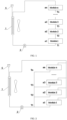
- the liquid cooling system comprises an external heat exchanger 1 and a cooling-fluid pump 2, and the cooling fluid is pushed by the cooling-fluid pump 2, sequentially passes through each of the modules, and finally flows back to the external heat exchanger 1.
- the external heat exchanger 1 is further provided with a liquid-level equalizer 5.
- the inlet temperature of one module is the outlet temperature of the previous one module, the inlet temperatures T of the subsequent modules gradually rise, T1 ⁇ T2 ⁇ T3 ⁇ ... ⁇ Tn, so ⁇ 1 > ⁇ 2 > ⁇ 3 > ... > ⁇ n. Therefore, it can be known that, the effect of temperature equalization of the series-connection system is poor.
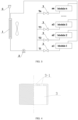
- the liquid cooling system comprises an external heat exchanger 1 and a cooling-fluid pump 2, and the cooling fluid is pushed by the cooling-fluid pump 2, enters the modules respectively from various inlets, and finally flows back to the external heat exchanger 1.
- the external heat exchanger 1 is further provided with a liquid-level equalizer 5.
- the flow rates of the cooling fluids that enter the modules are influenced by the resistances of the pipelines and factors such as the heights of the positions of the modules in the entire vehicle and the difference in the modules, which may cause different head pressures and different flow rates of the cooling fluids at the inlets.
- ⁇ 1 > ⁇ 2 > ⁇ 3 > ... > ⁇ n and accordingly ⁇ 1 > ⁇ 2 > ⁇ 3 > ... > ⁇ n. Therefore, it can be known that, the effect of temperature equalization of the parallel-connection system is not ideal either.
- EP2696433A1 discloses a cooling device for a car battery having a cooling body provided with channels for flow with a coolant, and thermally contacting to battery cells of a vehicle battery.
- An endcap is provided at an end of the cooling body, where the channels of the cooling body open into the endcap. Multiple projections are formed at the endcap and project into the channels of the cooling body.
- the endcap is formed as a coolant distributor with an inlet and an outlet of coolant, and as a lid element by which the coolant is turned back.
- DE102010032901A1 discloses a cooling device for lithium-ion battery of an electric vehicle, having a cooling base (18) comprising two flat lines (22, 24) with opposite flow directions, and an inlet distributor attached to one of the flat lines.
- a deflection element connects the two flat lines, and an external battery is attached to the other flat line.
- the flat lines are coplanarly arranged, where a flat side of the flat lines functions as a contact surface (20) for a battery cell group (14).
- Multiple coolant channels (38) are distributed over width (b) of the flat lines.
- the inlet distributor and the external battery comprise upper and lower parts.
- DE102012209302A1 describes a device for distributing coolants for cooling consumers (for example battery cells), with a common feed line or the consumers and a common return line, the common feed line and the return line having branches that connect to the consumers via hose pieces or connect hoses.
- a controllable throttle element is present between at least one branch of the common feed line and at least one consumer. By suitable control of the throttle elements, the consumers can be supplied with coolant with the same flow temperatures.
- US4578324A describes an active cooling system for cooling electrochemical cells that are arranged in a stack in a fuel cell or battery.
- the cooling system comprises cooling panels carrying a cooling fluid that flows adjacent to, and parallel to the plane of, each cell.
- the rate of cooling fluid flow past each cell is made to be substantially equal, so that each cell experiences substantially the same cooling environment, adding to the longevity of the fuel cell or battery. This can be accomplished by equalizing the resistance to cooling fluid flow for each cooling path, e.g., by using pressure equalizing, monotonically increasingly sized orifices in an input manifold.
- the present disclosure provides a battery energy storage system as defined in claim 1.
- an outer wall of the throttle pipe is provided with an external thread
- an inner wall of the feeding inlet is provided with an internal thread
- the throttle pipe and the feeding inlet are assembled together by the external thread and the internal thread.
- the throttle pipe is provided with a clip or a snap slot
- an inner wall of the feeding inlet is provided with a snap slot or a clip
- the throttle pipe and the feeding inlet are assembled together by snap fitting.
- the throttle pipe and the feeding inlet are assembled together by welding or adhesion.
- the top wall of the throttle pipe is provided with a hole or slot for fitting an assembling tool.
- the feeding inlet and a pipeline of the cooling fluid are integrally manufactured or separately manufactured; and the throttle pipe and the feeding inlet are integrally manufactured or separately manufactured.
- an outer wall of the feeding inlet is provided with a retreat stopping slot and a flange, and an inner wall of the feeding inlet is provided with a limiting mechanism, to limit and fix the throttle pipe.
- a method for flow equalization of a liquid cooling system of battery energy storage comprises according to lengths, directions and height differences of pipelines between battery modules and a cooling-fluid pump, calculating pressure losses of cooling fluids at feeding inlets, and providing the above-described device for flow equalization of a liquid cooling system of battery energy storage, to equalize flow rates at the battery modules.
- the throttle pipes are installed into the feeding inlets when the battery modules are being installed on a vehicle; and the method is usable for centralized battery modules or distributed battery modules.
- the present disclosure by employing the above structure configuration, has the following advantages:
- the present disclosure can enable the liquid cooling system to more uniformly distribute the flow rates of the cooling fluids among battery sub-packs or modules, thereby ensuring that the battery system operates at more uniform environmental temperatures, to reduce the difference in the performances of the modules, and prolong the service lives of the batteries.
- the detachable structure and serialized configuration of the throttle pipes of the present disclosure can ensure a simple and easy implementing process, which facilitates to improve the generalization and standardization of the modules.
- the throttle pipes of the present disclosure have a simple structure, obtain a significant effect of adjusting, and are easy to use.
- a device for flow equalization of a liquid cooling system of battery energy storage comprises a plurality of battery modules in parallel, which are a module 1, a module 2, a module 3,..., and a module n, each of the battery modules being connected to the liquid cooling system, and being provided with a cooling-fluid feeding inlet 4, wherein a throttle pipe 3 is provided in the feeding inlet 4, the throttle pipe 3 is provided with one or more flow restriction orifices 3-1, and the cooling fluids that enter the feeding inlets 4 are adjusted by the throttle pipes 3 to equal pressures.
- the feeding inlet 4 and the cooling-fluid pipeline are separately manufactured, and the throttle pipe 3 and the feeding inlet 4 are separately manufactured.
- the outer wall of the throttle pipe 3 is provided with an external thread
- the inner wall of the feeding inlet 4 is provided with an internal thread
- the throttle pipe 3 and the feeding inlet 4 are assembled together by the external thread and the internal thread.
- the throttle pipe 3 may be manufactured by using a metallic or non-metallic material.
- an end of the throttle pipe 3 in the axial direction is provided with an top wall
- the top wall is provided with a plurality of flow restriction orifices 3-1, and may also be provided with a single flow restriction orifice 3-1
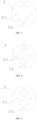
- the areas of the flow restriction orifices 3-1 of different throttle pipes 3 are different, as shown in Figs. 7, 8 and 9 , and by using different combinations of orifice diameters and orifice distributions the resistance coefficients with which the cooling fluids flow through the throttle pipes 3 are adjusted and the turbulence coefficients after the cooling fluids flow through the throttle pipes 3 are increased.
- the increasing of the turbulence coefficients after the cooling fluids flow through the throttle pipe 3 can further improve the heat exchange efficiency.
- the top wall is provided with six flow restriction orifices 3-1 arranged in a circle.
- the top wall is provided with six flow restriction orifices 3-1 arranged in a circle and one flow restriction orifice 3-1 in the center, and the central flow restriction orifice 3-1 and the peripheral flow restriction orifices 3-1 have equal orifice diameters.
- the top wall is provided with six flow restriction orifices 3-1 arranged in a circle and one flow restriction orifice 3-1 in the center, and the central flow restriction orifice 3-1 has an orifice diameter greater than those of the peripheral flow restriction orifices 3-1.
- the throttle pipes 3 for each of the battery modules it is required to, according to the lengths, the directions and the height differences of the pipelines between the battery modules and a cooling-fluid pump 2, calculate the pressure losses of the cooling fluids at the feeding inlets 4, and then provide the corresponding throttle pipes 3, to equalize the flow rates at the battery modules.
- the pipeline between a battery module and the cooling-fluid pump 2 is longer, has more turns, and has a greater height, it is required to install a throttle pipe 3 with a greater area of the flow restriction orifices 3-1, to increase the pressure of the cooling fluid that enters the feeding inlet 4.
- the pipeline between a battery module and the cooling-fluid pump 2 is shorter, has less turns, and has a less height, it is required to install a throttle pipe 3 with a less area of the flow restriction orifices 3-1, to reduce the pressure of the cooling fluid that enters the feeding inlet 4.
- the top wall of the throttle pipe 3 is provided with a hole 3-2 for fitting an assembling tool, and in installing the throttle pipe 3 the assembling tool may be inserted into the hole 3-2 to rotate the throttle pipe 3.
- that may be provided as a slot for fitting an assembling tool, wherein the slot does not penetrate through the top wall of the throttle pipe 3.
- the outer wall of the feeding inlet 4 is provided with a retreat stopping slot 4-1 and a flange 4-2.
- a retreat stopping slot 4-1 can improve the fastness of the connection with the cooling-fluid pipeline, to prevent disconnection from the cooling-fluid pipeline.
- the flange 4-2 serves to fix the feeding inlet 4.
- the flange 4-2 may be integrally manufactured with the feeding inlet 4, or be separately manufactured from and then assembled together with the feeding inlet 4.
- the inner wall of the feeding inlet 4 is provided with a limiting mechanism, for example a protrusion at the bottom end of the thread section, to limit and fix the throttle pipe 3, to prevent the throttle pipe 3 from entering too deep or loosening.
- a limiting mechanism for example a protrusion at the bottom end of the thread section
- the second embodiment of the present disclosure is an improvement that is made on the basis of the first embodiment.
- the second embodiment of the present disclosure differs from the first embodiment in that the throttle pipe 3 is provided with a clip or a snap slot, the inner wall of the feeding inlet 4 is provided with a snap slot or a clip, and the throttle pipe 3 and the feeding inlet 4 are assembled together by snap fitting.
- the throttle pipe 3 after the throttle pipe 3 has been inserted into the feeding inlet 4, the throttle pipe and the feeding inlet are assembled together by welding or adhesion.
- Welding or adhesion may serve as an assisting technical means for strengthening the connection, or welding or adhesion may be employed singly.
- the third embodiment of the present disclosure is an improvement that is made on the basis of the first embodiment.
- the third embodiment of the present disclosure differs from the first embodiment in that the feeding inlet 4 and the cooling-fluid pipeline are integrally manufactured, and the throttle pipe 3 and the feeding inlet 4 are integrally manufactured.
- the throttle pipe 3 and the feeding inlet 4 are integrally manufactured, which avoids the burden of installing the throttle pipe 3 in later stages.
- the feeding inlet 4 and the cooling-fluid pipeline may be separately manufactured, because the installation of the feeding inlet 4 in later stages is still convenient.
- the present embodiment provides a method for flow equalization of a liquid cooling system of battery energy storage.
- the method comprises according to the lengths, the directions and the height differences of the pipelines between battery modules and a cooling-fluid pump, calculating the pressure losses of the cooling fluids at feeding inlets, and then providing the corresponding device for flow equalization of a liquid cooling system of battery energy storage of the first embodiment, the second embodiment or the third embodiment, to equalize the flow rates at the battery modules.
- the device for flow equalization of a liquid cooling system of battery energy storage of the first embodiment or the second embodiment is provided, then different types of the throttle pipes 3 are installed into the feeding inlets 4 when the battery modules are being installed on a vehicle.
- the device for flow equalization of a liquid cooling system of battery energy storage of the third embodiment is provided, then when the battery modules are being installed on a vehicle it is required to install different types of the feeding inlets 4 or the liquid cooling system pipelines, or select suitable vehicle installation positions for different types of the battery modules.
- the method is usable for centralized battery modules or distributed battery modules.
- the battery system generally, according to the space restriction, employs a distributed layout of standard cases (battery sub-packs) of different specifications.
- the positions and heights for installation are different, wherein generally they are deployed side by side under the floor, and laminated at the vehicle tail.
- the losses of the head pressures at the inlets are calculated according to the lengths, the directions and the height differences of the pipelines between the standard cases and the cooling-fluid pump 2, , and then the corresponding throttle pipes are provided, to equalize the flow rates at the cases.
- throttle pipes 3 are installed when the battery sub-packs are being installed on a vehicle, in the production of the standard cases in the factory the environment for the vehicle installation is not required to be taken into consideration, which greatly improves the flexibility and convenience of field work.
- the battery system is generally in a centralized layout according to the enveloping space, wherein according to the demands modules of different specifications are installed in one battery pack.
- the losses of the head pressures at the inlets are calculated according to the lengths, the directions and the height differences of the pipelines between the modules and the cooling-fluid pump 2, , and then the corresponding throttle pipes are provided, to equalize the flow rates at the modules.
- the modules can be produced in standardized production, and the throttle pipes are installed when the battery packs are being assembled, whereby the module production is not required to take the positions into consideration, thereby improving the generalization degree and the convenience of the modules.
Landscapes
- Chemical & Material Sciences (AREA)
- Chemical Kinetics & Catalysis (AREA)
- Electrochemistry (AREA)
- General Chemical & Material Sciences (AREA)
- Engineering & Computer Science (AREA)
- Manufacturing & Machinery (AREA)
- Secondary Cells (AREA)
- Cooling, Air Intake And Gas Exhaust, And Fuel Tank Arrangements In Propulsion Units (AREA)
- Arrangement Or Mounting Of Propulsion Units For Vehicles (AREA)
- Battery Mounting, Suspending (AREA)
Claims (9)
- Batterieenergiespeichersystem, umfassend eine Vielzahl von parallel geschalteten Batteriemodulen, wobei jedes der Batteriemodule mit einem Flüssigkeitskühlungssystem verbunden ist und mit einem Kühlflüssigkeitszufuhreinlass (4) versehen ist, dadurch gekennzeichnet, dass:das Batterieenergiespeichersystem ferner eine Vorrichtung für den Strömungsausgleich umfasst, die Vorrichtung für den Strömungsausgleich eine Vielzahl von Drosselrohren (3) umfasst, eines der Drosselrohre (3) in jedem Zufuhreinlass (4) vorgesehen ist, das Drosselrohr (3) mit einer Strömungsbegrenzungsöffnung (3-1) versehen ist, und Kühlflüssigkeiten, die in die Zufuhreinlässe (4) einfließen, von den Drosselrohren (3) auf gleiche Drücke eingestellt werden;das Drosselrohr (3) in den Zufuhreinlass (4) hinein installiert ist, ein Ende des Drosselrohres (3) in einer axialen Richtung mit einer oberen Wand versehen ist, die obere Wand mit einer Vielzahl von Strömungsbegrenzungsöffnungen (3-1) versehen ist, Bereiche der Strömungsbegrenzungsöffnungen (3-1) von verschiedenen Drosselrohren (3) verschieden sind, und durch Verwendung von verschiedenen Kombinationen von Öffnungsdurchmessern und Öffnungsverteilungen, Widerstandskoeffizienten, mit welchen die Kühlflüssigkeiten durch die Drosselrohre (3) fließen, eingestellt werden.
- Batterieenergiespeichersystem nach Anspruch 1, dadurch gekennzeichnet, dass: eine Außenwand des Drosselrohres (3) mit einem Außengewinde versehen ist, eine Innenwand des Zufuhreinlasses (4) mit einem Innengewinde versehen ist, und das Drosselrohr (3) und der Zufuhreinlass (4) durch Verwendung des Außengewindes und des Innengewindes zusammengebaut werden.
- Batterieenergiespeichersystem nach Anspruch 1, dadurch gekennzeichnet, dass: das Drosselrohr (3) mit einer Schelle oder einem Einschnappschlitz versehen ist, eine Innenwand des Zufuhreinlasses (4) mit einem Einschnappschlitz oder einer Schelle versehen ist, und das Drosselrohr (3) und der Zufuhreinlass (4) durch Verschnappen zusammengebaut werden.
- Batterieenergiespeichersystem nach Anspruch 1, dadurch gekennzeichnet, dass: nachdem das Drosselrohr (3) in den Zufuhreinlass (4) hinein eingefügt worden ist, das Drosselrohr (3) und der Zufuhreinlass (4) durch Schweißen oder Kleben zusammengebaut werden.
- Batterieenergiespeichersystem nach Anspruch 1, dadurch gekennzeichnet, dass: die obere Wand des Drosselrohres (3) mit einem Loch oder einem Schlitz zum Einrasten eines Montierwerkzeugs (3-2) versehen ist.
- Batterieenergiespeichersystem nach Anspruch 1, dadurch gekennzeichnet, dass: der Zufuhreinlass (4) und eine Rohrleitung der Kühlflüssigkeit einstückig gefertigt oder getrennt gefertigt werden; und das Drosselrohr (3) und der Zufuhreinlass (4) einstückig gefertigt oder getrennt gefertigt werden.
- Batterieenergiespeichersystem nach Anspruch 1, dadurch gekennzeichnet, dass: eine Außenwand des Zufuhreinlasses (4) mit einem Rückzughalteschlitz (4-1) und einem Flansch (4-2) versehen ist, und eine Innenwand des Zufuhreinlasses (4) mit einem Begrenzungsmechanismus versehen ist, um das Drosselrohr (3) zu begrenzen und festzumontieren.
- Verfahren zum Strömungsausgleich eines Batterieenergiespeichersystems, dadurch gekennzeichnet, dass: das Verfahren, je nach Längen, Richtungen und Höhenunterschieden von Rohrleitungen zwischen Batteriemodulen und einer Kühlflüssigkeitspumpe (2), das Berechnen von Druckverlusten von Kühlflüssigkeiten an Zufuhreinlässen (4) und das Vorsehen der Vorrichtung zum Strömungsausgleich nach einem der Ansprüche 1-7 umfasst, um Durchflüsse an den Batteriemodulen auszugleichen.
- Verfahren zum Strömungsausgleich eines Batterieenergiespeichersystems nach Anspruch 8, dadurch gekennzeichnet, dass: die Drosselrohre (3) in die Zufuhreinlässe (4) hinein installiert sind, wenn die Batteriemodule an einem Fahrzeug gerade installiert werden; und das Verfahren für zentralisierte Batteriemodule oder verteilte Batteriemodule einsetzbar ist.
Applications Claiming Priority (2)
| Application Number | Priority Date | Filing Date | Title |
|---|---|---|---|
| CN201710599965.0A CN107403975B (zh) | 2017-07-21 | 2017-07-21 | 一种储能电池液冷系统均流装置和方法 |
| PCT/CN2017/094697 WO2019014960A1 (zh) | 2017-07-21 | 2017-07-27 | 一种电池储能液冷系统均流装置和方法 |
Publications (3)
| Publication Number | Publication Date |
|---|---|
| EP3637535A1 EP3637535A1 (de) | 2020-04-15 |
| EP3637535A4 EP3637535A4 (de) | 2020-06-17 |
| EP3637535B1 true EP3637535B1 (de) | 2023-07-12 |
Family
ID=60401136
Family Applications (1)
| Application Number | Title | Priority Date | Filing Date |
|---|---|---|---|
| EP17918547.5A Active EP3637535B1 (de) | 2017-07-21 | 2017-07-27 | Gleichförmige strömungsvorrichtung und verfahren für system zur kühlung einer batterieenergiespeicherflüssigkeit |
Country Status (5)
| Country | Link |
|---|---|
| US (1) | US20210091432A1 (de) |
| EP (1) | EP3637535B1 (de) |
| JP (1) | JP6775705B2 (de) |
| CN (1) | CN107403975B (de) |
| WO (1) | WO2019014960A1 (de) |
Families Citing this family (20)
| Publication number | Priority date | Publication date | Assignee | Title |
|---|---|---|---|---|
| CN108736109B (zh) * | 2018-04-17 | 2020-08-25 | 北京长城华冠汽车科技股份有限公司 | 电池热管理系统及电池温度的调节方法 |
| JP7138595B2 (ja) * | 2019-03-22 | 2022-09-16 | 株式会社ヴァレオジャパン | 車両用バッテリーの冷却システム |
| DE102020204584A1 (de) * | 2020-04-09 | 2021-10-14 | Mahle International Gmbh | Batterie für ein batteriebetriebenes Kraftfahrzeug |
| CN112599885A (zh) * | 2020-12-07 | 2021-04-02 | 合肥阳光新能源科技有限公司 | 一种液冷系统的控制方法及液冷系统 |
| JP7611751B2 (ja) * | 2021-03-30 | 2025-01-10 | 三菱重工業株式会社 | 流量計 |
| CN113206286B (zh) * | 2021-04-26 | 2023-11-14 | 佰凡电池(江苏)有限公司 | 一种锂离子电池配组系统 |
| CN116648811A (zh) * | 2021-05-31 | 2023-08-25 | 法雷奥日本株式会社 | 电池冷却单元及电池冷却系统 |
| EP4170777A1 (de) * | 2021-10-21 | 2023-04-26 | Rimac Automobiles Ltd. | Durchflussbegrenzer |
| CN114335807B (zh) * | 2021-12-30 | 2024-05-28 | 中联重科股份有限公司 | 电动矿用自卸车电池冷却系统及控制方法 |
| WO2023163976A1 (en) * | 2022-02-24 | 2023-08-31 | Tesla, Inc. | Passive fluid flow controlling device and system |
| CN117175055A (zh) * | 2022-05-27 | 2023-12-05 | 中化国际(控股)股份有限公司 | 一种液冷系统 |
| DE102022121853A1 (de) * | 2022-08-30 | 2024-02-29 | Kautex Textron Gmbh & Co. Kg | Fluidtemperierbare Traktionsbatterie |
| CN115472955A (zh) * | 2022-09-13 | 2022-12-13 | 安徽通盛能源科技有限公司 | 一种电池储能液冷系统均流装置和方法 |
| CN116364988A (zh) * | 2023-05-23 | 2023-06-30 | 上海弗列加滤清器有限公司 | 氢水分离器 |
| WO2024252490A1 (ja) | 2023-06-05 | 2024-12-12 | 株式会社Tbk | バッテリ温度調整システム |
| CN116435654B (zh) * | 2023-06-09 | 2023-11-28 | 宁德时代新能源科技股份有限公司 | 热管理系统及其控制方法、储能系统及用电装置 |
| CN118443097B (zh) * | 2024-04-30 | 2025-11-11 | 中国电子科技集团公司第三十研究所 | 液冷机箱流量分配测试方法 |
| CN118413982B (zh) * | 2024-05-24 | 2024-10-11 | 内蒙古中电储能技术有限公司 | 一种液冷储能系统的散热优化方法及系统 |
| FR3163492A1 (fr) * | 2024-06-18 | 2025-12-19 | Ampere Sas | Circuit de refroidissement pour une batterie pour un véhicule automobile électrique ou hybride rechargeable |
| CN118899588B (zh) * | 2024-07-01 | 2026-04-28 | 广州汽车集团股份有限公司 | 电池热管理方法、装置、电子设备、存储介质及程序产品 |
Family Cites Families (14)
| Publication number | Priority date | Publication date | Assignee | Title |
|---|---|---|---|---|
| US4578324A (en) * | 1984-10-05 | 1986-03-25 | Ford Aerospace & Communications Corporation | Active cooling system for electrochemical cells |
| EP1033772A3 (de) * | 1999-03-03 | 2000-09-13 | Matsushita Electric Industrial Co., Ltd. | Integrierte verschlossene Sekundärbatterie |
| CN201126849Y (zh) * | 2007-09-29 | 2008-10-01 | 严南根 | 用于电动车辆的电池单元组件 |
| JP5433427B2 (ja) * | 2010-01-04 | 2014-03-05 | 三菱重工業株式会社 | 電池パック |
| CN201707077U (zh) * | 2010-05-21 | 2011-01-12 | 上海华强浮罗仪表有限公司 | 平衡流量计 |
| DE102010032901A1 (de) * | 2010-07-30 | 2012-02-02 | Valeo Klimasysteme Gmbh | Kühlvorrichtung für eine Fahrzeugbatterie sowie Fahrzeugbatteriebaugruppe mit einer solchen Kühlvorrichtung |
| DE102010032899A1 (de) * | 2010-07-30 | 2012-02-02 | Valeo Klimasysteme Gmbh | Kühlvorrichtung für eine Fahrzeugbatterie sowie Fahrzeugbatteriebaugruppe mit einer solchen Kühlvorrichtung |
| DE102012209302A1 (de) * | 2012-06-01 | 2013-12-05 | Robert Bosch Gmbh | Kühlmittelverteilsystem |
| CN102745091B (zh) * | 2012-07-11 | 2015-10-07 | 潍柴动力股份有限公司 | 一种新能源汽车用动力电池箱装置及其控制方法 |
| EP2696433B1 (de) * | 2012-08-08 | 2015-03-04 | MAGNA STEYR Battery Systems GmbH & Co OG | Batteriekühlvorrichtung für eine Fahrzeugbatterie |
| DE102014108989A1 (de) * | 2014-06-26 | 2015-12-31 | Valeo Klimasysteme Gmbh | Verzweiger für einen Kältemittelstrom eines Kältemittelkreislaufs |
| CN105644381A (zh) * | 2015-12-23 | 2016-06-08 | 奇瑞汽车股份有限公司 | 一种电动汽车及其热管理系统 |
| CN106207311B (zh) * | 2016-08-31 | 2019-04-02 | 杭州捷能科技有限公司 | 一种动力电池系统的分布式双侧液冷系统及流量控制方法 |
| US11105566B2 (en) * | 2017-03-30 | 2021-08-31 | Nec Corporation | Heat exchanger, heat exchange system, and heat exchange method |
-
2017
- 2017-07-21 CN CN201710599965.0A patent/CN107403975B/zh active Active
- 2017-07-27 US US16/629,923 patent/US20210091432A1/en not_active Abandoned
- 2017-07-27 JP JP2020502616A patent/JP6775705B2/ja active Active
- 2017-07-27 WO PCT/CN2017/094697 patent/WO2019014960A1/zh not_active Ceased
- 2017-07-27 EP EP17918547.5A patent/EP3637535B1/de active Active
Also Published As
| Publication number | Publication date |
|---|---|
| WO2019014960A1 (zh) | 2019-01-24 |
| JP2020526902A (ja) | 2020-08-31 |
| US20210091432A1 (en) | 2021-03-25 |
| JP6775705B2 (ja) | 2020-10-28 |
| CN107403975B (zh) | 2019-09-27 |
| EP3637535A1 (de) | 2020-04-15 |
| EP3637535A4 (de) | 2020-06-17 |
| CN107403975A (zh) | 2017-11-28 |
Similar Documents
| Publication | Publication Date | Title |
|---|---|---|
| EP3637535B1 (de) | Gleichförmige strömungsvorrichtung und verfahren für system zur kühlung einer batterieenergiespeicherflüssigkeit | |
| KR102884018B1 (ko) | 냉매 분배기 | |
| US10991996B2 (en) | Battery heat exchange system | |
| CN106711533B (zh) | 热交换装置 | |
| US20250266527A1 (en) | Pipe connection assembly, liquid cooling system, battery and electric apparatus | |
| US9461346B2 (en) | Method for air cooling of an electric vehicle traction battery with flow shifting | |
| CN104051813A (zh) | 液体冷却的蓄电池模块 | |
| CN114267899A (zh) | 一种流量分配液冷板、电池总成、车辆及流量分配方法 | |
| CN105633501A (zh) | 电动车辆动力电池组液流热管理装置、管理系统及其控制方法 | |
| KR20230148362A (ko) | 배터리 냉각판 및 배터리 시스템 | |
| US20220196347A1 (en) | Temperature control device, in particular a cooling device for a motor vehicle | |
| EP3193127B1 (de) | Thermische spannungsentlastung für wärmetauscher | |
| CN107910614B (zh) | 一种动力电池液冷装置 | |
| CN209544560U (zh) | 电池模块换热装置及使用该装置的电池箱 | |
| CN115692935A (zh) | 电池换热集成结构及热管理系统 | |
| CN109494429B (zh) | 一种电动汽车电池包恒温控制系统及控制方法 | |
| CN111762063B (zh) | 电动汽车电池温控系统及方法 | |
| CN222939996U (zh) | 一种冷却单元以及电池包 | |
| CN109873242B (zh) | 一种电池热管理布置结构及电动汽车 | |
| CN220856702U (zh) | 液冷系统及应用其的电池箱 | |
| CN118281403A (zh) | 流道板、冷板组件、电池和用电设备 | |
| CN219066941U (zh) | 电池冷却装置、新能源车 | |
| CN220041981U (zh) | 一种电池预制舱水冷控制系统 | |
| CN220021258U (zh) | 电池包以及用电装置 | |
| CN220753541U (zh) | 复合相变材料耦合液冷的电池热管理装置 |
Legal Events
| Date | Code | Title | Description |
|---|---|---|---|
| STAA | Information on the status of an ep patent application or granted ep patent |
Free format text: STATUS: THE INTERNATIONAL PUBLICATION HAS BEEN MADE |
|
| PUAI | Public reference made under article 153(3) epc to a published international application that has entered the european phase |
Free format text: ORIGINAL CODE: 0009012 |
|
| STAA | Information on the status of an ep patent application or granted ep patent |
Free format text: STATUS: REQUEST FOR EXAMINATION WAS MADE |
|
| 17P | Request for examination filed |
Effective date: 20200108 |
|
| AK | Designated contracting states |
Kind code of ref document: A1 Designated state(s): AL AT BE BG CH CY CZ DE DK EE ES FI FR GB GR HR HU IE IS IT LI LT LU LV MC MK MT NL NO PL PT RO RS SE SI SK SM TR |
|
| AX | Request for extension of the european patent |
Extension state: BA ME |
|
| STAA | Information on the status of an ep patent application or granted ep patent |
Free format text: STATUS: EXAMINATION IS IN PROGRESS |
|
| A4 | Supplementary search report drawn up and despatched |
Effective date: 20200519 |
|
| RIC1 | Information provided on ipc code assigned before grant |
Ipc: H01M 10/6568 20140101ALI20200513BHEP Ipc: H01M 10/617 20140101ALI20200513BHEP Ipc: H01M 10/613 20140101AFI20200513BHEP Ipc: H01M 10/6556 20140101ALI20200513BHEP |
|
| 17Q | First examination report despatched |
Effective date: 20200603 |
|
| DAV | Request for validation of the european patent (deleted) | ||
| DAX | Request for extension of the european patent (deleted) | ||
| GRAP | Despatch of communication of intention to grant a patent |
Free format text: ORIGINAL CODE: EPIDOSNIGR1 |
|
| STAA | Information on the status of an ep patent application or granted ep patent |
Free format text: STATUS: GRANT OF PATENT IS INTENDED |
|
| INTG | Intention to grant announced |
Effective date: 20230203 |
|
| GRAS | Grant fee paid |
Free format text: ORIGINAL CODE: EPIDOSNIGR3 |
|
| GRAA | (expected) grant |
Free format text: ORIGINAL CODE: 0009210 |
|
| STAA | Information on the status of an ep patent application or granted ep patent |
Free format text: STATUS: THE PATENT HAS BEEN GRANTED |
|
| AK | Designated contracting states |
Kind code of ref document: B1 Designated state(s): AL AT BE BG CH CY CZ DE DK EE ES FI FR GB GR HR HU IE IS IT LI LT LU LV MC MK MT NL NO PL PT RO RS SE SI SK SM TR |
|
| P01 | Opt-out of the competence of the unified patent court (upc) registered |
Effective date: 20230530 |
|
| REG | Reference to a national code |
Ref country code: CH Ref legal event code: EP |
|
| REG | Reference to a national code |
Ref country code: DE Ref legal event code: R096 Ref document number: 602017071365 Country of ref document: DE |
|
| REG | Reference to a national code |
Ref country code: IE Ref legal event code: FG4D |
|
| REG | Reference to a national code |
Ref country code: LT Ref legal event code: MG9D |
|
| REG | Reference to a national code |
Ref country code: NL Ref legal event code: MP Effective date: 20230712 |
|
| REG | Reference to a national code |
Ref country code: AT Ref legal event code: MK05 Ref document number: 1588090 Country of ref document: AT Kind code of ref document: T Effective date: 20230712 |
|
| PG25 | Lapsed in a contracting state [announced via postgrant information from national office to epo] |
Ref country code: NL Free format text: LAPSE BECAUSE OF FAILURE TO SUBMIT A TRANSLATION OF THE DESCRIPTION OR TO PAY THE FEE WITHIN THE PRESCRIBED TIME-LIMIT Effective date: 20230712 |
|
| PG25 | Lapsed in a contracting state [announced via postgrant information from national office to epo] |
Ref country code: GR Free format text: LAPSE BECAUSE OF FAILURE TO SUBMIT A TRANSLATION OF THE DESCRIPTION OR TO PAY THE FEE WITHIN THE PRESCRIBED TIME-LIMIT Effective date: 20231013 |
|
| PG25 | Lapsed in a contracting state [announced via postgrant information from national office to epo] |
Ref country code: ES Free format text: LAPSE BECAUSE OF FAILURE TO SUBMIT A TRANSLATION OF THE DESCRIPTION OR TO PAY THE FEE WITHIN THE PRESCRIBED TIME-LIMIT Effective date: 20230712 |
|
| PG25 | Lapsed in a contracting state [announced via postgrant information from national office to epo] |
Ref country code: IS Free format text: LAPSE BECAUSE OF FAILURE TO SUBMIT A TRANSLATION OF THE DESCRIPTION OR TO PAY THE FEE WITHIN THE PRESCRIBED TIME-LIMIT Effective date: 20231112 |
|
| PG25 | Lapsed in a contracting state [announced via postgrant information from national office to epo] |
Ref country code: SE Free format text: LAPSE BECAUSE OF FAILURE TO SUBMIT A TRANSLATION OF THE DESCRIPTION OR TO PAY THE FEE WITHIN THE PRESCRIBED TIME-LIMIT Effective date: 20230712 Ref country code: RS Free format text: LAPSE BECAUSE OF FAILURE TO SUBMIT A TRANSLATION OF THE DESCRIPTION OR TO PAY THE FEE WITHIN THE PRESCRIBED TIME-LIMIT Effective date: 20230712 Ref country code: PT Free format text: LAPSE BECAUSE OF FAILURE TO SUBMIT A TRANSLATION OF THE DESCRIPTION OR TO PAY THE FEE WITHIN THE PRESCRIBED TIME-LIMIT Effective date: 20231113 Ref country code: NO Free format text: LAPSE BECAUSE OF FAILURE TO SUBMIT A TRANSLATION OF THE DESCRIPTION OR TO PAY THE FEE WITHIN THE PRESCRIBED TIME-LIMIT Effective date: 20231012 Ref country code: LV Free format text: LAPSE BECAUSE OF FAILURE TO SUBMIT A TRANSLATION OF THE DESCRIPTION OR TO PAY THE FEE WITHIN THE PRESCRIBED TIME-LIMIT Effective date: 20230712 Ref country code: LT Free format text: LAPSE BECAUSE OF FAILURE TO SUBMIT A TRANSLATION OF THE DESCRIPTION OR TO PAY THE FEE WITHIN THE PRESCRIBED TIME-LIMIT Effective date: 20230712 Ref country code: IS Free format text: LAPSE BECAUSE OF FAILURE TO SUBMIT A TRANSLATION OF THE DESCRIPTION OR TO PAY THE FEE WITHIN THE PRESCRIBED TIME-LIMIT Effective date: 20231112 Ref country code: HR Free format text: LAPSE BECAUSE OF FAILURE TO SUBMIT A TRANSLATION OF THE DESCRIPTION OR TO PAY THE FEE WITHIN THE PRESCRIBED TIME-LIMIT Effective date: 20230712 Ref country code: GR Free format text: LAPSE BECAUSE OF FAILURE TO SUBMIT A TRANSLATION OF THE DESCRIPTION OR TO PAY THE FEE WITHIN THE PRESCRIBED TIME-LIMIT Effective date: 20231013 Ref country code: FI Free format text: LAPSE BECAUSE OF FAILURE TO SUBMIT A TRANSLATION OF THE DESCRIPTION OR TO PAY THE FEE WITHIN THE PRESCRIBED TIME-LIMIT Effective date: 20230712 Ref country code: ES Free format text: LAPSE BECAUSE OF FAILURE TO SUBMIT A TRANSLATION OF THE DESCRIPTION OR TO PAY THE FEE WITHIN THE PRESCRIBED TIME-LIMIT Effective date: 20230712 Ref country code: AT Free format text: LAPSE BECAUSE OF FAILURE TO SUBMIT A TRANSLATION OF THE DESCRIPTION OR TO PAY THE FEE WITHIN THE PRESCRIBED TIME-LIMIT Effective date: 20230712 |
|
| PG25 | Lapsed in a contracting state [announced via postgrant information from national office to epo] |
Ref country code: PL Free format text: LAPSE BECAUSE OF FAILURE TO SUBMIT A TRANSLATION OF THE DESCRIPTION OR TO PAY THE FEE WITHIN THE PRESCRIBED TIME-LIMIT Effective date: 20230712 |
|
| REG | Reference to a national code |
Ref country code: CH Ref legal event code: PL |
|
| REG | Reference to a national code |
Ref country code: BE Ref legal event code: MM Effective date: 20230731 |
|
| PG25 | Lapsed in a contracting state [announced via postgrant information from national office to epo] |
Ref country code: LU Free format text: LAPSE BECAUSE OF NON-PAYMENT OF DUE FEES Effective date: 20230727 |
|
| PG25 | Lapsed in a contracting state [announced via postgrant information from national office to epo] |
Ref country code: LU Free format text: LAPSE BECAUSE OF NON-PAYMENT OF DUE FEES Effective date: 20230727 |
|
| REG | Reference to a national code |
Ref country code: DE Ref legal event code: R097 Ref document number: 602017071365 Country of ref document: DE |
|
| REG | Reference to a national code |
Ref country code: IE Ref legal event code: MM4A |
|
| PG25 | Lapsed in a contracting state [announced via postgrant information from national office to epo] |
Ref country code: SM Free format text: LAPSE BECAUSE OF FAILURE TO SUBMIT A TRANSLATION OF THE DESCRIPTION OR TO PAY THE FEE WITHIN THE PRESCRIBED TIME-LIMIT Effective date: 20230712 Ref country code: RO Free format text: LAPSE BECAUSE OF FAILURE TO SUBMIT A TRANSLATION OF THE DESCRIPTION OR TO PAY THE FEE WITHIN THE PRESCRIBED TIME-LIMIT Effective date: 20230712 Ref country code: EE Free format text: LAPSE BECAUSE OF FAILURE TO SUBMIT A TRANSLATION OF THE DESCRIPTION OR TO PAY THE FEE WITHIN THE PRESCRIBED TIME-LIMIT Effective date: 20230712 Ref country code: DK Free format text: LAPSE BECAUSE OF FAILURE TO SUBMIT A TRANSLATION OF THE DESCRIPTION OR TO PAY THE FEE WITHIN THE PRESCRIBED TIME-LIMIT Effective date: 20230712 Ref country code: CZ Free format text: LAPSE BECAUSE OF FAILURE TO SUBMIT A TRANSLATION OF THE DESCRIPTION OR TO PAY THE FEE WITHIN THE PRESCRIBED TIME-LIMIT Effective date: 20230712 Ref country code: CH Free format text: LAPSE BECAUSE OF NON-PAYMENT OF DUE FEES Effective date: 20230731 Ref country code: SK Free format text: LAPSE BECAUSE OF FAILURE TO SUBMIT A TRANSLATION OF THE DESCRIPTION OR TO PAY THE FEE WITHIN THE PRESCRIBED TIME-LIMIT Effective date: 20230712 Ref country code: MC Free format text: LAPSE BECAUSE OF FAILURE TO SUBMIT A TRANSLATION OF THE DESCRIPTION OR TO PAY THE FEE WITHIN THE PRESCRIBED TIME-LIMIT Effective date: 20230712 |
|
| PLBE | No opposition filed within time limit |
Free format text: ORIGINAL CODE: 0009261 |
|
| STAA | Information on the status of an ep patent application or granted ep patent |
Free format text: STATUS: NO OPPOSITION FILED WITHIN TIME LIMIT |
|
| PG25 | Lapsed in a contracting state [announced via postgrant information from national office to epo] |
Ref country code: IT Free format text: LAPSE BECAUSE OF FAILURE TO SUBMIT A TRANSLATION OF THE DESCRIPTION OR TO PAY THE FEE WITHIN THE PRESCRIBED TIME-LIMIT Effective date: 20230712 Ref country code: BE Free format text: LAPSE BECAUSE OF NON-PAYMENT OF DUE FEES Effective date: 20230731 |
|
| 26N | No opposition filed |
Effective date: 20240415 |
|
| PG25 | Lapsed in a contracting state [announced via postgrant information from national office to epo] |
Ref country code: IE Free format text: LAPSE BECAUSE OF NON-PAYMENT OF DUE FEES Effective date: 20230727 |
|
| PG25 | Lapsed in a contracting state [announced via postgrant information from national office to epo] |
Ref country code: IE Free format text: LAPSE BECAUSE OF NON-PAYMENT OF DUE FEES Effective date: 20230727 Ref country code: SI Free format text: LAPSE BECAUSE OF FAILURE TO SUBMIT A TRANSLATION OF THE DESCRIPTION OR TO PAY THE FEE WITHIN THE PRESCRIBED TIME-LIMIT Effective date: 20230712 |
|
| PG25 | Lapsed in a contracting state [announced via postgrant information from national office to epo] |
Ref country code: BG Free format text: LAPSE BECAUSE OF FAILURE TO SUBMIT A TRANSLATION OF THE DESCRIPTION OR TO PAY THE FEE WITHIN THE PRESCRIBED TIME-LIMIT Effective date: 20230712 |
|
| PG25 | Lapsed in a contracting state [announced via postgrant information from national office to epo] |
Ref country code: BG Free format text: LAPSE BECAUSE OF FAILURE TO SUBMIT A TRANSLATION OF THE DESCRIPTION OR TO PAY THE FEE WITHIN THE PRESCRIBED TIME-LIMIT Effective date: 20230712 |
|
| PG25 | Lapsed in a contracting state [announced via postgrant information from national office to epo] |
Ref country code: CY Free format text: LAPSE BECAUSE OF FAILURE TO SUBMIT A TRANSLATION OF THE DESCRIPTION OR TO PAY THE FEE WITHIN THE PRESCRIBED TIME-LIMIT; INVALID AB INITIO Effective date: 20170727 |
|
| PG25 | Lapsed in a contracting state [announced via postgrant information from national office to epo] |
Ref country code: HU Free format text: LAPSE BECAUSE OF FAILURE TO SUBMIT A TRANSLATION OF THE DESCRIPTION OR TO PAY THE FEE WITHIN THE PRESCRIBED TIME-LIMIT; INVALID AB INITIO Effective date: 20170727 |
|
| PGFP | Annual fee paid to national office [announced via postgrant information from national office to epo] |
Ref country code: DE Payment date: 20250711 Year of fee payment: 9 |
|
| PGFP | Annual fee paid to national office [announced via postgrant information from national office to epo] |
Ref country code: GB Payment date: 20250723 Year of fee payment: 9 |
|
| PGFP | Annual fee paid to national office [announced via postgrant information from national office to epo] |
Ref country code: FR Payment date: 20250730 Year of fee payment: 9 |
|
| PG25 | Lapsed in a contracting state [announced via postgrant information from national office to epo] |
Ref country code: TR Free format text: LAPSE BECAUSE OF FAILURE TO SUBMIT A TRANSLATION OF THE DESCRIPTION OR TO PAY THE FEE WITHIN THE PRESCRIBED TIME-LIMIT Effective date: 20230712 |