EP3637290B1 - Unlocking control method and related product - Google Patents
Unlocking control method and related product Download PDFInfo
- Publication number
- EP3637290B1 EP3637290B1 EP18835435.1A EP18835435A EP3637290B1 EP 3637290 B1 EP3637290 B1 EP 3637290B1 EP 18835435 A EP18835435 A EP 18835435A EP 3637290 B1 EP3637290 B1 EP 3637290B1
- Authority
- EP
- European Patent Office
- Prior art keywords
- biometric
- electronic device
- biometric information
- information
- recognition
- Prior art date
- Legal status (The legal status is an assumption and is not a legal conclusion. Google has not performed a legal analysis and makes no representation as to the accuracy of the status listed.)
- Active
Links
- 238000000034 method Methods 0.000 title claims description 60
- 230000033001 locomotion Effects 0.000 claims description 98
- 230000001133 acceleration Effects 0.000 claims description 45
- 238000013441 quality evaluation Methods 0.000 claims description 44
- 238000012545 processing Methods 0.000 claims description 17
- 238000010586 diagram Methods 0.000 description 14
- 230000006870 function Effects 0.000 description 10
- 238000011156 evaluation Methods 0.000 description 8
- 238000004891 communication Methods 0.000 description 6
- 230000008569 process Effects 0.000 description 6
- 230000003287 optical effect Effects 0.000 description 5
- 210000003462 vein Anatomy 0.000 description 5
- 210000004556 brain Anatomy 0.000 description 4
- 238000004590 computer program Methods 0.000 description 4
- 239000004065 semiconductor Substances 0.000 description 4
- 230000008878 coupling Effects 0.000 description 3
- 238000010168 coupling process Methods 0.000 description 3
- 238000005859 coupling reaction Methods 0.000 description 3
- 230000005236 sound signal Effects 0.000 description 3
- 238000006073 displacement reaction Methods 0.000 description 2
- 230000000694 effects Effects 0.000 description 2
- 238000005516 engineering process Methods 0.000 description 2
- 230000005484 gravity Effects 0.000 description 2
- 230000000007 visual effect Effects 0.000 description 2
- 230000009471 action Effects 0.000 description 1
- 230000009286 beneficial effect Effects 0.000 description 1
- 230000005540 biological transmission Effects 0.000 description 1
- 230000001419 dependent effect Effects 0.000 description 1
- 238000011982 device technology Methods 0.000 description 1
- 238000007599 discharging Methods 0.000 description 1
- 238000000605 extraction Methods 0.000 description 1
- 230000002349 favourable effect Effects 0.000 description 1
- 238000001914 filtration Methods 0.000 description 1
- 230000007774 longterm Effects 0.000 description 1
- 238000013507 mapping Methods 0.000 description 1
- 238000010295 mobile communication Methods 0.000 description 1
- 238000010079 rubber tapping Methods 0.000 description 1
- 239000007787 solid Substances 0.000 description 1
- 230000007704 transition Effects 0.000 description 1
- XLYOFNOQVPJJNP-UHFFFAOYSA-N water Substances O XLYOFNOQVPJJNP-UHFFFAOYSA-N 0.000 description 1
Images

Classifications
-
- G—PHYSICS
- G06—COMPUTING; CALCULATING OR COUNTING
- G06F—ELECTRIC DIGITAL DATA PROCESSING
- G06F21/00—Security arrangements for protecting computers, components thereof, programs or data against unauthorised activity
- G06F21/30—Authentication, i.e. establishing the identity or authorisation of security principals
- G06F21/31—User authentication
- G06F21/32—User authentication using biometric data, e.g. fingerprints, iris scans or voiceprints
-
- G—PHYSICS
- G06—COMPUTING; CALCULATING OR COUNTING
- G06V—IMAGE OR VIDEO RECOGNITION OR UNDERSTANDING
- G06V40/00—Recognition of biometric, human-related or animal-related patterns in image or video data
- G06V40/10—Human or animal bodies, e.g. vehicle occupants or pedestrians; Body parts, e.g. hands
- G06V40/12—Fingerprints or palmprints
- G06V40/1365—Matching; Classification
-
- G—PHYSICS
- G06—COMPUTING; CALCULATING OR COUNTING
- G06V—IMAGE OR VIDEO RECOGNITION OR UNDERSTANDING
- G06V40/00—Recognition of biometric, human-related or animal-related patterns in image or video data
- G06V40/60—Static or dynamic means for assisting the user to position a body part for biometric acquisition
- G06V40/63—Static or dynamic means for assisting the user to position a body part for biometric acquisition by static guides
-
- G—PHYSICS
- G06—COMPUTING; CALCULATING OR COUNTING
- G06V—IMAGE OR VIDEO RECOGNITION OR UNDERSTANDING
- G06V40/00—Recognition of biometric, human-related or animal-related patterns in image or video data
- G06V40/70—Multimodal biometrics, e.g. combining information from different biometric modalities
-
- H—ELECTRICITY
- H04—ELECTRIC COMMUNICATION TECHNIQUE
- H04W—WIRELESS COMMUNICATION NETWORKS
- H04W12/00—Security arrangements; Authentication; Protecting privacy or anonymity
- H04W12/06—Authentication
-
- H—ELECTRICITY
- H04—ELECTRIC COMMUNICATION TECHNIQUE
- H04L—TRANSMISSION OF DIGITAL INFORMATION, e.g. TELEGRAPHIC COMMUNICATION
- H04L2463/00—Additional details relating to network architectures or network communication protocols for network security covered by H04L63/00
- H04L2463/082—Additional details relating to network architectures or network communication protocols for network security covered by H04L63/00 applying multi-factor authentication
-
- Y—GENERAL TAGGING OF NEW TECHNOLOGICAL DEVELOPMENTS; GENERAL TAGGING OF CROSS-SECTIONAL TECHNOLOGIES SPANNING OVER SEVERAL SECTIONS OF THE IPC; TECHNICAL SUBJECTS COVERED BY FORMER USPC CROSS-REFERENCE ART COLLECTIONS [XRACs] AND DIGESTS
- Y02—TECHNOLOGIES OR APPLICATIONS FOR MITIGATION OR ADAPTATION AGAINST CLIMATE CHANGE
- Y02D—CLIMATE CHANGE MITIGATION TECHNOLOGIES IN INFORMATION AND COMMUNICATION TECHNOLOGIES [ICT], I.E. INFORMATION AND COMMUNICATION TECHNOLOGIES AIMING AT THE REDUCTION OF THEIR OWN ENERGY USE
- Y02D30/00—Reducing energy consumption in communication networks
- Y02D30/70—Reducing energy consumption in communication networks in wireless communication networks
Definitions
- the present disclosure relates to the field of electronic device technologies, and more particular, to an unlocking control method and related products.
- multi-biometric authentication is increasingly favored by electronic equipment manufacturers.
- the electronic device is also in motion, so the captured biological information (for example, a fingerprint image) may be blurred, thereby reducing the efficiency of multi-biometric authentication.
- EP3188406A1 discloses an identity authentication method and apparatus, and user equipment, and relates to the field of information technologies, so that when a surrounding environment is not favorable for user authentication, and a current environment is relatively safe, a matching threshold for performing authentication by user equipment can be reduced, avoiding a case in which identity authentication needs to be repeated multiple times due to impact of a surrounding environment, and improving accuracy of identity authentication.
- the method includes: first detecting a scenario in which the user equipment is located; determining, from at least two different authentication levels, an authentication level corresponding to the scenario in which the user equipment is located; then acquiring current biometric feature data entered by a user; and finally determining, according to the current biometric feature data, preconfigured biometric feature data, and the authentication level, whether identity authentication succeeds.
- the present invention is applicable to user identity authentication.
- CN106407776A discloses a terminal control method and a terminal.
- the method comprises the steps of obtaining current motion parameters of the terminal in a first preset time length; determining a similarity threshold value according to the current motion parameters and historical motion parameters of the terminal; and collecting a current fingerprint, and carrying out processing on the terminal according to the current fingerprint and the similarity threshold value.
- the adjustment on the similarity threshold value is realized base on comparison of the motion parameters (namely a user use habit); therefore, when the fingerprint identification is subsequently carried out, even though fingers of a user are in a certain special situation (such as relatively much water on the fingers), because of the adjustment on the similarity threshold value, the user does not need to input the fingerprint repeatedly for multiple times for identification; and thus, the efficiency of the fingerprint identification is improved.
- GB2517562A discloses an example method.
- the method includes capturing, by a camera of a mobile computing device, an image, determining whether the image includes a representation of at least a portion of a face, and, when the image includes the representation of at least the portion of the face, analyzing characteristics of the image.
- the characteristics include at least one of a tonal distribution of the image that is associated with a darkness-based mapping of a plurality of pixels of the image, and a plurality of spatial frequencies of the image that are associated with a visual transition between adjacent pixels of the image.
- the method further includes classifying, by the mobile computing device, a quality of the image based at least in part on the analyzed characteristics of the image.
- CN201638241U relates to a fingerprint identification device, which comprises an optical fingerprint collector, a semiconductor fingerprint collector, an optical fingerprint feature template storage area, a semiconductor fingerprint feature template storage area, a fingerprint identification module and a gate, wherein one input end of the gate is connected with the optical fingerprint collector, the other input end thereof is connected with the semiconductor fingerprint collector and the output end thereof is connected with the fingerprint identification module; and the input end of the gate is sequentially repeatedly switched between the optical fingerprint collector and the semiconductor fingerprint collector.
- the utility model improves the applicability of the fingerprint identification device to dry and wet fingers, which is beneficial to the popularization and the application of a fingerprint identification product.
- Embodiments of the invention provide an unlocking control method and related products, to solve the problem that a foldable and flexible display is inconvenient to be unlocked in a folded state.
- the invention is defined by independent claims.
- Preferred embodiments of the invention are defined by features of dependent claims.
- the embodiment of the disclosure includes the operations of: detecting whether the electronic device is in a motion state; reducing a first recognition threshold to obtain a second recognition threshold when the electronic device is in a motion state; acquiring first biometric information when a matching value between first biometric information and first preset biometric template information is greater than the second recognition threshold; and acquiring second biometric information and performing an recognition operation on the second biometric information.
- the recognition threshold is reduced, thereby improving the efficiency of biometric recognition.
- the electronic device referred to in the embodiments of the disclosure may include various handheld devices having wireless communication functions, in-vehicle devices, wearable devices, computing devices, or other processing devices connected to a wireless modem, and various forms of user equipment (UE), mobile station (MS), terminal device, etc.
- UE user equipment
- MS mobile station
- terminal device etc.
- the devices mentioned above are collectively referred to as electronic devices.
- Embodiments of the disclosure are described in detail below.
- the electronic device in the embodiment of the disclosure may be installed with a multi-biometric device, and the multi-biometric device may be composed of a number of biometric devices.
- the biometric devices may include, but are not limited to, a fingerprint recognition device, an iris recognition device, a face recognition device, a vein recognition device, an electroencephalogram recognition device, an electrocardiogram recognition device, and the like, each of the biometric devices has a corresponding recognition algorithm and a recognition threshold, and each of the biometric devices has a corresponding template preset by a user.
- the fingerprint recognition device has a preset fingerprint template corresponding thereto.
- the fingerprint recognition device can collect a fingerprint image, and pass the recognition when a matching value between the fingerprint image and the preset fingerprint template is greater than a corresponding recognition threshold.
- a multi-biometric recognition mode in the embodiment of the disclosure may include two or more recognition operations, for example, a fingerprint recognition is performed at first, and then a face recognition can be performed after the passing of the fingerprint recognition, or, the fingerprint recognition and the face recognition can be performed synchronously.
- the multi-biometric recognition mode has better security than a single biometric recognition mode (for example, unlocking just by fingerprint recognition), and thus, the multi-biometric recognition mode is becoming more and more popular.
- first biometric information may include, but is not limited to, fingerprint information, iris information, face information, vein information, brain wave information, electrocardiogram information, and the like.
- Second biometric information may include, but is not limited to, fingerprint information, iris information, face information, vein information, brain wave information, electrocardiogram information, and the like.
- a first biometric device is configured to acquire the first biometric information
- the first biometric device may be one of the follows: a fingerprint recognition device, an iris recognition device, a face recognition device, a vein recognition device, a brain wave recognition device, and an electroencephalogram recognition device, and the like.
- a second biometric device is configured to acquire the second biometric information
- the second biometric device may be one of the follows: a fingerprint recognition device, an iris recognition device, a face recognition device, a vein recognition device, a brain wave recognition device, and an electroencephalogram recognition device, and the like.
- the first biometric information may be different from the second biometric information.
- the first biometric information is fingerprint information
- the second biometric information is iris information.
- the first biometric information is iris information
- the second biometric information is face information.
- the first biometric information is face information
- the second biometric information is iris information.
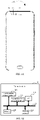
- FIG. 1A illustrates an exemplary smart phone 1000
- an iris recognition device of the smart phone 1000 may include an infrared fill light 21 and an infrared camera 22.
- infrared lights emitted from the infrared fill light 21 reach the iris, and are reflected by the iris and then back to the infrared camera 22, so the iris recognition device can capture images of the iris.
- a front camera 23 can be used as a face recognition device.
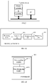
- FIG. 1B is a schematic structural diagram of an electronic device 100.
- the electronic device 100 includes an application processor (AP) 110, a first biometric device 120, a second biometric device 130, a motion sensor 160 and a memory 140.
- the AP 110 is connected with the first biometric device 120, the second biometric device 130, the motion sensor 160, and the memory 140 via a bus 150.
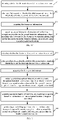
- FIG. 1C is a schematic flowchart of an unlocking control method according to an embodiment of the disclosure.
- the unlocking control method is applied to an electronic device, wherein its physical map and structural diagram can be referred to FIG. 1A or FIG. IB.
- the unlocking control method described in this embodiment includes the following steps.
- the electronic device is detected whether it is in a motion state or not.
- the electronic device can detect whether it is in motion by the following sensors, such as an acceleration sensor, a displacement sensor, a vibration sensor, a pedometer sensor, a gyroscope, and the like.
- the following step 102 can be performed when the electronic device is in motion.
- the foregoing step 101 of detecting whether the electronic device is in a motion state or not may include the following steps:
- the gyroscope in the lens will also follow the movement.
- the motion curve has a horizontal axis of time and a vertical axis of displacement from the equilibrium position.
- the characteristic parameters can be derived from the motion curve, which can include, but are not limited to, speed, acceleration, amplitude, and the like. These characteristic parameters can be used to detect whether the electronic device is in motion.
- the above step A3 of detecting whether the electronic device is in a motion state according to the characteristic parameters may be implemented as follows: determining the electronic device is in a motion state when an acceleration is greater than a first threshold and an amplitude is greater than a second threshold.
- the first threshold and the second threshold may be set by the user or by the system.
- the foregoing step 101 of detecting whether the electronic device is in a motion state may include the following steps:
- the electronic device When the electronic device is in motion, the captured images are likely to be blurred. Therefore, when more than one image is captured, it can be judged whether every image is blurred or not. If so, the electronic device is determined to be in motion. For example, when three images are captured and all three images are blurred, the electronic device is determined to be in motion.
- the following method may be adopted: determining a blurred region of any image, and determining the image is blurred when the area of the blurred region is larger than a preset blurred area.
- the image When the electronic device is in a motion state, the image may be blurred. Therefore, the first recognition threshold may be appropriately reduced to obtain the second recognition threshold, thereby improving the recognition efficiency.
- the foregoing step 102 of reducing a first recognition threshold and thereby to obtain a second recognition threshold may include the following steps:
- Accelerations during a specified time period are determined by the gyroscope in the lens, and then the accelerations during the specified time period is averaged to obtain the average acceleration.
- the first proportional coefficient corresponding to the average acceleration is determined according to the preset correspondence between the accelerations and the proportional coefficients, and further, the first recognition threshold is reduced to obtain the second recognition threshold, according to the first proportional coefficient.
- the proportional coefficient is in a range of 0 ⁇ 1. In this way, the recognition threshold can be reduced based on the acceleration.
- the larger the acceleration the smaller the proportional coefficient. For example, when the acceleration is 5 m/s, the first proportional coefficient is 0.8, and when the acceleration is 8 m/s, the first proportional coefficient is 0.6.
- the first biometric information maybe image information or characteristic texture information (i.e., information obtained after performing feature extraction on the image information).
- the foregoing step 103 of acquiring the first biometric information may include the following steps:
- the motion speed of the electronic device can be detected, and the motion speed can be an average speed implemented by a step counter sensor.
- the motion speeds and the anti-shake coefficients can be preset, and the corresponding anti-shake coefficient corresponding to the acquired motion speed can be determined according to the correspondence, and further, the first biometric information can be acquired according to the corresponding anti-shake coefficient.
- the above anti-shake coefficient is an anti-shake coefficient for the camera, so that the camera can acquire the first biometric information more stably, thereby reducing a blurred region of the captured image.
- the following step may be further included: performing image enhancement processing on the first biometric information.
- the first biometric information may be an image, for example, an iris image.
- Image enhancement processing may include, but is not limited to, image denoising (e.g., wavelet transform for image denoising), image restoration (e.g., Wiener filtering), dark visual enhancement algorithms (e.g., histogram equalization, grayscale stretching, etc.), and the like.
- image denoising e.g., wavelet transform for image denoising
- image restoration e.g., Wiener filtering
- dark visual enhancement algorithms e.g., histogram equalization, grayscale stretching, etc.
- the first biometric information after the image enhancement processing may be matched with the first preset biometric template.
- step 103 the following steps may be further included:
- the preset quality threshold may be set by the user or set by the system by default.
- the first biometric information may be processed by image quality evaluation to obtain the image quality evaluation value, and the quality of the iris image is determined by the image quality evaluation value. Taking the iris image as an example, when the image quality evaluation value is greater than or equal to the preset quality threshold, the iris image is considered to be qualified, and when the image quality evaluation value is less than the preset quality threshold, the iris image may be considered to be unqualified, thus image enhancement processing may be performed on the first biometric information.
- the first biometric information may be performed image quality evaluation with at least one image quality evaluation index, thereby obtaining the image quality evaluation value.
- a number of image quality evaluation indexes may be included, and each image quality evaluation index corresponds to a weight. Thus, when performing image quality evaluation on the image with each of the image quality evaluation indexes, corresponding evaluation results can be obtained. Finally, the obtained evaluation results are weighted to obtain the image quality evaluation value.
- the image quality evaluation indexes may include, but are not limited to, average value, standard deviation, entropy, sharpness, signal to noise ratio, and the like.
- image quality evaluation indexes can be used to evaluate the image quality. It is not the more evaluation indexes, the better the evaluation result, when evaluating image quality. Because the more evaluation indexes, the higher the computational complexity of the image quality evaluation process, and such may not result in a better effect to evaluate the image quality. Thus, 2-10 image quality evaluation indexes may be adopted to evaluate the image quality, in the case of high requirements for image quality evaluation. Specifically, the number of image quality evaluation indexes and which indexes are selected, are determined according to specific implementation situations. Of course, the image quality evaluation indexes should be selected in combination with specific scenes, and the image quality evaluation indexes selected in the dark environment and that selected in the bright environment are different.
- just one image quality evaluation index may be used for evaluation.
- the image waited to be processed is evaluated using the entropy, it can be considered that the larger the entropy, the better the image quality, and conversely, the smaller the entropy, the worse the image quality.
- the image may be evaluated by using a number of image quality evaluation indexes, the weight of each image quality evaluation index may be set, when obtaining a number of image quality evaluation values, a final image quality evaluation value may be obtained according to the image quality evaluation values and corresponding weights thereof.
- three quality evaluation indexes are A index, B index and C index, the weight of A is a1, the weight of B is a2, and the weight of C is a3.
- the image quality evaluation value corresponding to A is b1
- the image quality evaluation value corresponding to B is b2
- the image quality evaluation value corresponding to C is b3
- the final image quality evaluation value a1b1+a2b2+a3b3.
- the larger the image quality evaluation value the better the image quality.
- the first preset biometric template information may be pre-stored and implemented by a user registration before performing the step 101.
- the first preset biometric template information is collected by a first biometric device.
- the first biometric information is matched with the first preset biometric template information, and thereby to obtain a matching value between the first biometric information and the first preset biometric template information.
- the matching value is greater than the second recognition threshold, the second biometric information can be obtained, and the recognition operation is performed on the second biometric information.
- the following step may be further included: reminding the user to re-input the first biometric information, when the matching value between the first biometric information and the first preset biometric template information is less than or equal to the second recognition threshold.
- the user is prompted to reenter the first biometric information.
- the embodiment of the disclosure includes the operations of: detecting whether the electronic device is in a motion state; reducing a first recognition threshold to obtain a second recognition threshold when the electronic device is in a motion state; acquiring first biometric information when a matching value between first biometric information and first preset biometric template information is greater than the second recognition threshold; and acquiring second biometric information and performing an recognition operation on the second biometric information.
- the recognition threshold is reduced, thereby improving the efficiency of biometric recognition.
- FIG. 2 is a schematic flowchart of an unlocking control method according to an embodiment of the disclosure.
- the unlocking control method is applied to an electronic device, wherein its physical map or structural diagram is illustrated in FIG. 1A or FIG. IB.
- the unlocking control method described in this embodiment includes the following steps.
- a third recognition threshold is reduced to obtain a fourth recognition threshold.
- the user is prompted to reenter the first biometric information.
- the foregoing step 204 of reducing the third recognition threshold to obtain the fourth recognition threshold may include the following steps:
- the instantaneous accelerations can be obtained by the gyroscope in the lens, and the instantaneous acceleration can be understood as the acceleration acquired at the most recent moment.
- the second proportional coefficient corresponding to the average acceleration may be determined according to the preset correspondence between the accelerations and the proportional coefficients, and further, the third recognition threshold is reduced to obtain the fourth recognition threshold, according to the second proportional coefficient.
- the above-mentioned proportional coefficient is in a range of 0 ⁇ 1.
- the recognition threshold can be reduced based on the acceleration. In the specific implementation, it maybe, the larger the acceleration, the smaller the proportional coefficient. For example, when the acceleration is 5 m/s, the first proportional coefficient is 0.8, and when the acceleration is 8 m/s, the first proportional coefficient is 0.6.
- second biometric information is acquired, and the second biometric information is matched with the second preset biometric template information.
- the second preset biometric template information may be pre-stored and implemented by a user registration before performing the step 201.
- the second preset biometric template information is collected by a second biometric device.
- the second biometric information is matched with the second preset biometric template information.
- the foregoing step 205 of acquiring the first biometric information may include the following steps:
- the motion speed of the electronic device can be detected, and the motion speed can be an average speed obtained from a step counter sensor.
- the more intense the motion the more the camera shakes. Therefore, a correspondence between the motion speeds and the anti-shake coefficients can be preset, and the corresponding anti-shake coefficient corresponding to the acquired motion speed can be determined according to the correspondence, and further, the second biometric information can be acquired according to the corresponding anti-shake coefficient.
- the above anti-shake coefficient is an anti-shake coefficient for the camera, so that the camera can acquire the second biometric information more stably, thereby reducing a blurred region of the captured image.
- an unlocking operation is performed on the electronic device, when a matching value between the second biometric information and second preset biometric template information is greater than the fourth recognition threshold.
- the unlocking operation may be performed.
- the unlocking operation may be understood as: lighting the screen of the electronic device and entering the main page, or, entering the main page of the electronic device when it is in a bright screen state, or, entering a specified page of a certain application when the unlocking operation is for the application, wherein the specified page maybe set by the user or set by the system by default.
- the embodiment of the disclosure includes the operations of: detecting whether the electronic device is in a motion state; reducing a first recognition threshold to obtain a second recognition threshold when the electronic device is in a motion state; acquiring first biometric information when a matching value between first biometric information and first preset biometric template information is greater than the second recognition threshold; and acquiring second biometric information and performing an recognition operation on the second biometric information.
- the recognition threshold is reduced, thereby improving the efficiency of biometric recognition.
- FIG. 3 is an electronic device according to an embodiment of the disclosure.
- the electronic device includes an application processor AP, a memory; and one or more programs stored in the memory and executable by the AP.
- the one or more programs includes instructions for performing the following steps:
- the program in the operation of detecting whether the electronic device is in a motion state or not, includes instructions configured to execute the following steps:
- the program includes instructions configured to execute the following steps:
- the program in the operation of acquiring the first biometric information, includes instructions configured to execute the following steps:
- the program includes instructions configured to execute the following step:
- the program includes instructions configured to execute the following step: reminding the user to re-input first biometric information, when the matching value between the first biometric information and the first preset biometric template information is less than or equal to the second recognition threshold.
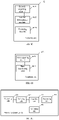
- FIG. 4A is a schematic structural diagram of an unlocking control device according to one embodiment of the disclosure.
- the unlocking control device is applied in an electronic device, and includes a detecting unit 401, a reducing unit 402, an acquiring unit 403 and a processing unit 404.
- the detecting unit 401 is configured to detect whether the electronic device is in a motion state or not.
- the reducing unit 402 is configured to reduce a first recognition threshold to obtain a second recognition threshold, when the electronic device is in a motion state.
- the acquiring unit 403 is configured to acquire first biometric information.
- the processing unit 404 is configured to acquiring second biometric information and performing a recognition operation on the second biometric information, when a matching value between the first biometric recognition information and the first preset biometric template information is greater than a second recognition threshold.
- FIG. 4B is a specific detailed structure of the detecting unit 401 of the unlocking control device of FIG. 4A .
- the detecting unit 402 may include a first acquiring module 4011 and a first determining module 4012, details are as follows.
- the first acquiring module 4011 is configured to acquire a motion curve using a gyroscope in a lens.
- the first determining module 4012 is configured to determine characteristic parameters of the motion curve.
- the first determining module 4012 is further configured to detect whether the electronic device is in a motion state or not according to the characteristic parameters.
- FIG. 4C is a specific detailed structure of the reducing unit 402 of the unlocking control device of FIG. 4A .
- the reducing unit 402 may include a second acquiring module 4021, a second determining module 4022 and a reducing module 4023, and details are as follows.
- the second acquiring module 4021 is configured to acquire an average acceleration of the electronic device.
- the second determining module 4022 is configured to determine, according to a preset correspondence between accelerations and proportional coefficients, a first proportional coefficient corresponding to the average acceleration.
- the reducing module 4023 is configured to reduce the first recognition threshold to obtain the second recognition threshold, according to the first proportional coefficient.
- FIG. 4D is a specific detailed structure of the acquiring unit 403 of the unlocking control device of FIG. 4A .
- the acquiring unit 403 may include a third acquiring module 4031 and a third determining module 4032, and details are as follows.
- the third acquiring module 4031 is configured to acquire a motion speed of the electronic device.
- the third determining module 4032 is configured to determine an anti-shake coefficient corresponding to the motion speed.
- the third acquiring module 4031 is further configured to acquire the first biometric information according to the anti-shake coefficient.
- the reducing unit 402 is specifically configured to reduce a third recognition threshold to obtain a fourth recognition threshold.
- the specific implementation manner in which the processing unit 404 performs the recognition operation on the second biometric information is:
- FIG. 4E is a modified structure of the unlocking control device shown in FIG. 4A .
- the unlocking control device of FIG. 4E further includes a reminding unit 405 as follows.
- the reminding unit 405 is configured to remind the user to re-input first biometric information, when the matching value between the first biometric information and the first preset biometric template information is less than or equal to the second recognition threshold.
- the embodiment of the disclosure includes the operations of: detecting whether the electronic device is in a motion state; reducing a first recognition threshold to obtain a second recognition threshold when the electronic device is in a motion state; acquiring first biometric information when a matching value between first biometric information and first preset biometric template information is greater than the second recognition threshold; and acquiring second biometric information and performing an recognition operation on the second biometric information.
- the recognition threshold is reduced, thereby improving the efficiency of biometric recognition.
- FIG. 5 illustrates another electronic device, according to an embodiment of the disclosure.
- the electronic device may be any terminal device selected form a mobile phone, a tablet computer, a personal digital assistant (PDA), a point of sales (POS), an in-vehicle computer, and the like.
- PDA personal digital assistant
- POS point of sales
- in-vehicle computer and the like.
- the mobile phone is taken as an example.
- FIG. 5 is a block diagram showing a part of structures of a mobile phone related to an electronic device provided by an embodiment of the disclosure.
- the mobile phone includes a radio frequency (RF) circuit 910, a memory 920, an input unit 930, a sensor 950, an audio circuit 960, a wireless fidelity (WiFi) module 970, an application processor (AP) 980, a power supply 990 and the like.
- RF radio frequency
- RF radio frequency
- memory 920 includes a radio frequency (RF) circuit 910, a memory 920, an input unit 930, a sensor 950, an audio circuit 960, a wireless fidelity (WiFi) module 970, an application processor (AP) 980, a power supply 990 and the like.
- WiFi wireless fidelity
- AP application processor
- the input unit 930 can be used to receive input numeric or character information, as well as to generate signal inputs related to user settings and function controls.
- the input unit 930 can include a touch display 933, a multi-biometric device 931 and other input devices 932.
- the multi-biometric device 931 at least includes two biometric devices (e.g., face recognition device and iris recognition device).
- the input unit 930 also includes other input devices 932.
- other input devices 932 may include, but are not limited to, one or more of a physical keyboard, function keys (such as volume control buttons, switch buttons, etc.), a trackball, a mouse, a joystick, and the like.
- the AP 980 is configured to execute the operations of:
- the AP 980 is the control center of the mobile phone, which connects various portions of the entire phone using various interfaces and lines, by performing or executing software programs and/or modules stored in the memory 920, and by invoking data stored in the memory 920, thereby implementing the various functions of the mobile phone and processing data to monitor the mobile phone.
- the AP 980 may include one or more processing cores.
- the AP 980 may integrate an application processor and a modem processor, where the application processor mainly processes the operating system, the user interfaces, the applications, and the like, and the modem processor primarily handles wireless communications. It will be understood that the above described modem processor may also not be integrated into the AP 980.
- the memory 920 can include a high speed random access memory, and can also include a non-volatile memory, such as at least one magnetic disk storage device, a flash memory device, or other volatile solid state storage device.
- a non-volatile memory such as at least one magnetic disk storage device, a flash memory device, or other volatile solid state storage device.
- the RF circuit 910 can be used for transmitting and receiving messages.
- the RF circuit 910 includes, but is not limited to, an antenna, at least one amplifier, a tuner, one or more oscillators, a Subscriber Identity Module (SIM) card, a transceiver, a coupler, a low noise amplifier (LNA), and a duplexer, etc.
- SIM Subscriber Identity Module
- the RF circuit 910 can also communicate with the network and other devices through wireless communication.
- the wireless communication may use any communication standard or protocol, including but not limited to Global System of Mobile communication (GSM), General Packet Radio Service (GPRS), Code Division Multiple Access (CDMA), Wideband Code Division Multiple Access (WCDMA), Long Term Evolution (LTE), e-mail, Short Messaging Service (SMS), and the like.
- GSM Global System of Mobile communication
- GPRS General Packet Radio Service
- CDMA Code Division Multiple Access
- WCDMA Wideband Code Division Multiple Access
- LTE Long Term Evolution
- SMS Short Messaging Service
- the mobile phone also can include at least one type of the sensor 950, such as a light sensor, a motion sensor, and other sensors.
- the light sensor may include an ambient light sensor and a proximity sensor, wherein the ambient light sensor may adjust the brightness of the touch display according to the brightness of the ambient light, and the proximity sensor may close the touch display and/or the backlight when the mobile phone moves to the ear of the user.
- a gravity acceleration sensor can detect the magnitude of acceleration in all directions (usually three axes). When it is stationary, it can detect the magnitude and direction of gravity.
- Other sensors such as gyroscopes, barometers, hygrometers, thermometers, infrared sensors, etc., also can be disposed in the mobile phone and are not detailed here.
- the audio circuit 960, a speaker 961, and a microphone 962 can provide an audio interface between the user and the terminal 900.
- the audio circuit 960 can convert the received audio data into electrical signals and transmit the electrical signals to the speaker 961, the speaker 961 converts the electrical signals into sound signals and output the sound signals.
- the microphone 962 converts the collected sound signals into electrical signals, the electrical signals are received by the audio circuit 960 and then converted into audio data, the audio data is then processed by the AP 980, and then is sent to another terminal via the RF circuitry 910, or the audio data is output to the memory 920 for further processing.
- WiFi is a short-range wireless transmission technology
- the mobile phone can help users to send and receive emails, browse web pages, and access streaming media through the WiFi module 970, which provides wireless broadband internet access for users.
- FIG. 5 shows the WiFi module 970, it can be understood that it is not the necessary configuration of the terminal, and may be omitted as needed within the scope of not changing the essence of the disclosure.
- the mobile phone also includes the power supply 990 (such as a battery) that supplies power to the various components.
- the power supply 990 can be logically coupled to the AP 980 through a power management system to manage functions such as charging, discharging, and power management.
- the mobile phone may further include a camera, a Bluetooth module, and the like, and details are not described herein again.
- each step, method, or operation can be implemented based on the structure of the mobile phone.
- each unit can be implemented based on the structure of the mobile phone.
- the embodiment of the disclosure further provides a computer storage medium, wherein the computer storage medium stores a computer program, which enables the computer to execute a part of steps or all steps of any of the unlocking control method as described in the foregoing method embodiments.
- the embodiment of the disclosure further provides a computer program product, which includes a non-transitory computer readable storage medium storing a computer program, the computer program being executable to enable a computer to perform a part of steps or all steps of the unlocking control method recited in the foregoing method embodiments.
- the disclosed device may be implemented in other manners.
- the device embodiments described above are merely illustrative.
- the division of the unit is only a logical function division.
- there may be another division manner such as multiple units or components may be combined or may be integrated into another system, or some features can be omitted or not executed.
- the mutual coupling or direct coupling or communication connection shown or discussed may be an indirect coupling or communicating connection through some interfaces, devices or units, and may be electrical or other ways.
- the units described as separate components maybe or maybe not physically separated, and the components shown as units maybe or maybe not physical units, that is, the component may be located in one place, or may be distributed to several network units. Some or all of the units may be selected according to actual needs to achieve the purpose of the solution of the embodiment.
- Each functional unit in the embodiment of the disclosure may be integrated into one processing module, or each unit may exist physically separately, or two or more units may be integrated into one module.
- the above integrated modules can be implemented in the form of hardware or in the form of software functional modules.
- the integrated modules if implemented in the form of software functional modules and sold or used as stand-alone products, may also be stored in a computer readable storage medium.
- the software product is stored in a memory, and includes a number of instructions configured to enable a computer device (may be a personal computer, a server or a network device, etc.) to perform all or part of the steps of the methods described in the embodiments of the disclosure.
- the foregoing memory includes a U disk, a read-only memory (ROM), a random access memory (RAM), a mobile hard disk, a magnetic disk, or an optical disk, and the like, that can store program codes.
Applications Claiming Priority (2)
| Application Number | Priority Date | Filing Date | Title |
|---|---|---|---|
| CN201710585207.3A CN107451446B (zh) | 2017-07-18 | 2017-07-18 | 解锁控制方法及相关产品 |
| PCT/CN2018/095942 WO2019015575A1 (zh) | 2017-07-18 | 2018-07-17 | 解锁控制方法及相关产品 |
Publications (3)
| Publication Number | Publication Date |
|---|---|
| EP3637290A1 EP3637290A1 (en) | 2020-04-15 |
| EP3637290A4 EP3637290A4 (en) | 2020-04-29 |
| EP3637290B1 true EP3637290B1 (en) | 2022-08-31 |
Family
ID=60487776
Family Applications (1)
| Application Number | Title | Priority Date | Filing Date |
|---|---|---|---|
| EP18835435.1A Active EP3637290B1 (en) | 2017-07-18 | 2018-07-17 | Unlocking control method and related product |
Country Status (4)
| Country | Link |
|---|---|
| US (1) | US11055547B2 (zh) |
| EP (1) | EP3637290B1 (zh) |
| CN (1) | CN107451446B (zh) |
| WO (1) | WO2019015575A1 (zh) |
Families Citing this family (10)
| Publication number | Priority date | Publication date | Assignee | Title |
|---|---|---|---|---|
| CN107451446B (zh) * | 2017-07-18 | 2020-05-26 | Oppo广东移动通信有限公司 | 解锁控制方法及相关产品 |
| CN108418682A (zh) * | 2018-02-11 | 2018-08-17 | 广东欧珀移动通信有限公司 | 密码生成方法及相关产品 |
| CN108519810B (zh) * | 2018-03-07 | 2021-04-09 | Oppo广东移动通信有限公司 | 电子装置、脑电波解锁方法及相关产品 |
| CN110020619A (zh) * | 2019-03-28 | 2019-07-16 | 维沃移动通信有限公司 | 一种指纹识别方法及移动终端 |
| CN113312950A (zh) * | 2020-09-24 | 2021-08-27 | 一令通(上海)科技有限公司 | 一种基于人脸和虹膜特征的身份认证方法 |
| CN112532885B (zh) * | 2020-11-27 | 2022-05-03 | 维沃移动通信有限公司 | 防抖方法、装置及电子设备 |
| CN112802240B (zh) * | 2020-12-31 | 2022-04-15 | 西南交通大学 | 一种基于脑电波的保险解锁方法 |
| CN114385012B (zh) * | 2022-01-17 | 2023-06-30 | 维沃移动通信有限公司 | 运动的识别方法、装置、电子设备和可读存储介质 |
| CN114626038A (zh) * | 2022-01-26 | 2022-06-14 | 安徽点亮网络技术有限公司 | 一种身份验证方法、系统及装置 |
| CN114858200B (zh) * | 2022-04-19 | 2023-06-27 | 合众新能源汽车股份有限公司 | 车辆传感器检测到的对象的质量评价方法及装置 |
Citations (1)
| Publication number | Priority date | Publication date | Assignee | Title |
|---|---|---|---|---|
| CN201638241U (zh) * | 2010-02-11 | 2010-11-17 | 苏州市职业大学 | 一种指纹识别装置 |
Family Cites Families (18)
| Publication number | Priority date | Publication date | Assignee | Title |
|---|---|---|---|---|
| US6947609B2 (en) * | 2002-03-04 | 2005-09-20 | Xerox Corporation | System with motion triggered processing |
| JP5230501B2 (ja) * | 2009-03-26 | 2013-07-10 | 富士フイルム株式会社 | 認証装置及び認証方法 |
| US9372979B2 (en) * | 2011-01-07 | 2016-06-21 | Geoff Klein | Methods, devices, and systems for unobtrusive mobile device user recognition |
| US8441548B1 (en) * | 2012-06-15 | 2013-05-14 | Google Inc. | Facial image quality assessment |
| US9928413B2 (en) | 2013-06-13 | 2018-03-27 | Intel Corporation | Techniques for user authentication on a computing device via pattern recognition |
| CN103618832B (zh) * | 2013-11-29 | 2016-06-22 | 广东欧珀移动通信有限公司 | 一种用于移动终端的信息提示方法及终端 |
| CA2902093C (en) | 2014-08-28 | 2023-03-07 | Kevin Alan Tussy | Facial recognition authentication system including path parameters |
| CN110489952A (zh) * | 2014-09-30 | 2019-11-22 | 华为技术有限公司 | 身份认证的方法、装置及用户设备 |
| US10263967B2 (en) * | 2015-09-01 | 2019-04-16 | Quantum Interface, Llc | Apparatuses, systems and methods for constructing unique identifiers |
| CN106156688A (zh) * | 2015-03-10 | 2016-11-23 | 上海骏聿数码科技有限公司 | 一种动态人脸识别方法及系统 |
| CN106250751B (zh) | 2016-07-18 | 2019-09-17 | 青岛海信移动通信技术股份有限公司 | 一种移动设备及调整体征信息检测阈值的方法 |
| CN106250825A (zh) * | 2016-07-22 | 2016-12-21 | 厚普(北京)生物信息技术有限公司 | 一种在医保应用中场景自适应的人脸识别系统 |
| CN106407776A (zh) * | 2016-08-30 | 2017-02-15 | 深圳市金立通信设备有限公司 | 一种终端控制方法及终端 |
| CN106599651A (zh) * | 2016-11-17 | 2017-04-26 | 努比亚技术有限公司 | 一种终端解锁装置和方法 |
| CN106599660A (zh) * | 2016-12-02 | 2017-04-26 | 宇龙计算机通信科技(深圳)有限公司 | 终端安全验证方法及装置 |
| US10586031B2 (en) * | 2016-12-21 | 2020-03-10 | Fingerprint Cards Ab | Biometric authentication of a user |
| CN106599875A (zh) * | 2016-12-23 | 2017-04-26 | 努比亚技术有限公司 | 指纹识别装置及方法 |
| CN107451446B (zh) * | 2017-07-18 | 2020-05-26 | Oppo广东移动通信有限公司 | 解锁控制方法及相关产品 |
-
2017
- 2017-07-18 CN CN201710585207.3A patent/CN107451446B/zh active Active
-
2018
- 2018-07-17 EP EP18835435.1A patent/EP3637290B1/en active Active
- 2018-07-17 WO PCT/CN2018/095942 patent/WO2019015575A1/zh unknown
- 2018-07-17 US US16/624,229 patent/US11055547B2/en active Active
Patent Citations (1)
| Publication number | Priority date | Publication date | Assignee | Title |
|---|---|---|---|---|
| CN201638241U (zh) * | 2010-02-11 | 2010-11-17 | 苏州市职业大学 | 一种指纹识别装置 |
Also Published As
| Publication number | Publication date |
|---|---|
| CN107451446B (zh) | 2020-05-26 |
| US11055547B2 (en) | 2021-07-06 |
| WO2019015575A1 (zh) | 2019-01-24 |
| CN107451446A (zh) | 2017-12-08 |
| US20200193199A1 (en) | 2020-06-18 |
| EP3637290A4 (en) | 2020-04-29 |
| EP3637290A1 (en) | 2020-04-15 |
Similar Documents
| Publication | Publication Date | Title |
|---|---|---|
| EP3637290B1 (en) | Unlocking control method and related product | |
| CN107480496B (zh) | 解锁控制方法及相关产品 | |
| US11074466B2 (en) | Anti-counterfeiting processing method and related products | |
| EP3623973B1 (en) | Unlocking control method and related product | |
| CN107590461B (zh) | 人脸识别方法及相关产品 | |
| CN107862265B (zh) | 图像处理方法及相关产品 | |
| CN107292285B (zh) | 虹膜活体检测方法及相关产品 | |
| CN107609514B (zh) | 人脸识别方法及相关产品 | |
| RU2731370C1 (ru) | Способ распознавания живого организма и терминальное устройство | |
| CN107403147B (zh) | 虹膜活体检测方法及相关产品 | |
| CN107463818B (zh) | 解锁控制方法及相关产品 | |
| CN106951767B (zh) | 解锁控制方法及相关产品 | |
| CN107423699B (zh) | 活体检测方法及相关产品 | |
| US11782478B2 (en) | Unlocking control method and related products | |
| CN107657218B (zh) | 人脸识别方法及相关产品 | |
| CN107451454B (zh) | 解锁控制方法及相关产品 | |
| CN107784271B (zh) | 指纹识别方法及相关产品 | |
| CN107679481B (zh) | 解锁控制方法及相关产品 | |
| CN107506708B (zh) | 解锁控制方法及相关产品 | |
| CN110909695B (zh) | 防伪处理方法及相关产品 | |
| CN107545163B (zh) | 解锁控制方法及相关产品 | |
| WO2019015574A1 (zh) | 解锁控制方法及相关产品 | |
| CN107358183B (zh) | 虹膜活体检测方法及相关产品 | |
| CN110889692A (zh) | 移动支付方法和电子设备 | |
| CN107194363B (zh) | 图像饱和度处理方法、装置、存储介质及计算机设备 |
Legal Events
| Date | Code | Title | Description |
|---|---|---|---|
| STAA | Information on the status of an ep patent application or granted ep patent |
Free format text: STATUS: THE INTERNATIONAL PUBLICATION HAS BEEN MADE |
|
| PUAI | Public reference made under article 153(3) epc to a published international application that has entered the european phase |
Free format text: ORIGINAL CODE: 0009012 |
|
| STAA | Information on the status of an ep patent application or granted ep patent |
Free format text: STATUS: REQUEST FOR EXAMINATION WAS MADE |
|
| 17P | Request for examination filed |
Effective date: 20191209 |
|
| AK | Designated contracting states |
Kind code of ref document: A1 Designated state(s): AL AT BE BG CH CY CZ DE DK EE ES FI FR GB GR HR HU IE IS IT LI LT LU LV MC MK MT NL NO PL PT RO RS SE SI SK SM TR |
|
| AX | Request for extension of the european patent |
Extension state: BA ME |
|
| A4 | Supplementary search report drawn up and despatched |
Effective date: 20200327 |
|
| RIC1 | Information provided on ipc code assigned before grant |
Ipc: H04W 12/06 20090101ALI20200324BHEP Ipc: G06F 21/32 20130101AFI20200324BHEP |
|
| DAV | Request for validation of the european patent (deleted) | ||
| DAX | Request for extension of the european patent (deleted) | ||
| STAA | Information on the status of an ep patent application or granted ep patent |
Free format text: STATUS: EXAMINATION IS IN PROGRESS |
|
| 17Q | First examination report despatched |
Effective date: 20210322 |
|
| GRAP | Despatch of communication of intention to grant a patent |
Free format text: ORIGINAL CODE: EPIDOSNIGR1 |
|
| STAA | Information on the status of an ep patent application or granted ep patent |
Free format text: STATUS: GRANT OF PATENT IS INTENDED |
|
| RIC1 | Information provided on ipc code assigned before grant |
Ipc: H04W 12/06 20090101ALI20220401BHEP Ipc: G06F 21/32 20130101AFI20220401BHEP |
|
| INTG | Intention to grant announced |
Effective date: 20220422 |
|
| GRAS | Grant fee paid |
Free format text: ORIGINAL CODE: EPIDOSNIGR3 |
|
| GRAA | (expected) grant |
Free format text: ORIGINAL CODE: 0009210 |
|
| STAA | Information on the status of an ep patent application or granted ep patent |
Free format text: STATUS: THE PATENT HAS BEEN GRANTED |
|
| AK | Designated contracting states |
Kind code of ref document: B1 Designated state(s): AL AT BE BG CH CY CZ DE DK EE ES FI FR GB GR HR HU IE IS IT LI LT LU LV MC MK MT NL NO PL PT RO RS SE SI SK SM TR |
|
| REG | Reference to a national code |
Ref country code: CH Ref legal event code: EP Ref country code: GB Ref legal event code: FG4D |
|
| REG | Reference to a national code |
Ref country code: AT Ref legal event code: REF Ref document number: 1515827 Country of ref document: AT Kind code of ref document: T Effective date: 20220915 |
|
| REG | Reference to a national code |
Ref country code: DE Ref legal event code: R096 Ref document number: 602018040120 Country of ref document: DE |
|
| REG | Reference to a national code |
Ref country code: IE Ref legal event code: FG4D |
|
| REG | Reference to a national code |
Ref country code: LT Ref legal event code: MG9D |
|
| REG | Reference to a national code |
Ref country code: NL Ref legal event code: MP Effective date: 20220831 |
|
| PG25 | Lapsed in a contracting state [announced via postgrant information from national office to epo] |
Ref country code: SE Free format text: LAPSE BECAUSE OF FAILURE TO SUBMIT A TRANSLATION OF THE DESCRIPTION OR TO PAY THE FEE WITHIN THE PRESCRIBED TIME-LIMIT Effective date: 20220831 Ref country code: RS Free format text: LAPSE BECAUSE OF FAILURE TO SUBMIT A TRANSLATION OF THE DESCRIPTION OR TO PAY THE FEE WITHIN THE PRESCRIBED TIME-LIMIT Effective date: 20220831 Ref country code: NO Free format text: LAPSE BECAUSE OF FAILURE TO SUBMIT A TRANSLATION OF THE DESCRIPTION OR TO PAY THE FEE WITHIN THE PRESCRIBED TIME-LIMIT Effective date: 20221130 Ref country code: LV Free format text: LAPSE BECAUSE OF FAILURE TO SUBMIT A TRANSLATION OF THE DESCRIPTION OR TO PAY THE FEE WITHIN THE PRESCRIBED TIME-LIMIT Effective date: 20220831 Ref country code: LT Free format text: LAPSE BECAUSE OF FAILURE TO SUBMIT A TRANSLATION OF THE DESCRIPTION OR TO PAY THE FEE WITHIN THE PRESCRIBED TIME-LIMIT Effective date: 20220831 Ref country code: FI Free format text: LAPSE BECAUSE OF FAILURE TO SUBMIT A TRANSLATION OF THE DESCRIPTION OR TO PAY THE FEE WITHIN THE PRESCRIBED TIME-LIMIT Effective date: 20220831 |
|
| REG | Reference to a national code |
Ref country code: AT Ref legal event code: MK05 Ref document number: 1515827 Country of ref document: AT Kind code of ref document: T Effective date: 20220831 |
|
| PG25 | Lapsed in a contracting state [announced via postgrant information from national office to epo] |
Ref country code: PL Free format text: LAPSE BECAUSE OF FAILURE TO SUBMIT A TRANSLATION OF THE DESCRIPTION OR TO PAY THE FEE WITHIN THE PRESCRIBED TIME-LIMIT Effective date: 20220831 Ref country code: IS Free format text: LAPSE BECAUSE OF FAILURE TO SUBMIT A TRANSLATION OF THE DESCRIPTION OR TO PAY THE FEE WITHIN THE PRESCRIBED TIME-LIMIT Effective date: 20221231 Ref country code: HR Free format text: LAPSE BECAUSE OF FAILURE TO SUBMIT A TRANSLATION OF THE DESCRIPTION OR TO PAY THE FEE WITHIN THE PRESCRIBED TIME-LIMIT Effective date: 20220831 Ref country code: GR Free format text: LAPSE BECAUSE OF FAILURE TO SUBMIT A TRANSLATION OF THE DESCRIPTION OR TO PAY THE FEE WITHIN THE PRESCRIBED TIME-LIMIT Effective date: 20221201 |
|
| PG25 | Lapsed in a contracting state [announced via postgrant information from national office to epo] |
Ref country code: SM Free format text: LAPSE BECAUSE OF FAILURE TO SUBMIT A TRANSLATION OF THE DESCRIPTION OR TO PAY THE FEE WITHIN THE PRESCRIBED TIME-LIMIT Effective date: 20220831 Ref country code: RO Free format text: LAPSE BECAUSE OF FAILURE TO SUBMIT A TRANSLATION OF THE DESCRIPTION OR TO PAY THE FEE WITHIN THE PRESCRIBED TIME-LIMIT Effective date: 20220831 Ref country code: PT Free format text: LAPSE BECAUSE OF FAILURE TO SUBMIT A TRANSLATION OF THE DESCRIPTION OR TO PAY THE FEE WITHIN THE PRESCRIBED TIME-LIMIT Effective date: 20230102 Ref country code: ES Free format text: LAPSE BECAUSE OF FAILURE TO SUBMIT A TRANSLATION OF THE DESCRIPTION OR TO PAY THE FEE WITHIN THE PRESCRIBED TIME-LIMIT Effective date: 20220831 Ref country code: DK Free format text: LAPSE BECAUSE OF FAILURE TO SUBMIT A TRANSLATION OF THE DESCRIPTION OR TO PAY THE FEE WITHIN THE PRESCRIBED TIME-LIMIT Effective date: 20220831 Ref country code: CZ Free format text: LAPSE BECAUSE OF FAILURE TO SUBMIT A TRANSLATION OF THE DESCRIPTION OR TO PAY THE FEE WITHIN THE PRESCRIBED TIME-LIMIT Effective date: 20220831 Ref country code: AT Free format text: LAPSE BECAUSE OF FAILURE TO SUBMIT A TRANSLATION OF THE DESCRIPTION OR TO PAY THE FEE WITHIN THE PRESCRIBED TIME-LIMIT Effective date: 20220831 |
|
| PG25 | Lapsed in a contracting state [announced via postgrant information from national office to epo] |
Ref country code: SK Free format text: LAPSE BECAUSE OF FAILURE TO SUBMIT A TRANSLATION OF THE DESCRIPTION OR TO PAY THE FEE WITHIN THE PRESCRIBED TIME-LIMIT Effective date: 20220831 Ref country code: EE Free format text: LAPSE BECAUSE OF FAILURE TO SUBMIT A TRANSLATION OF THE DESCRIPTION OR TO PAY THE FEE WITHIN THE PRESCRIBED TIME-LIMIT Effective date: 20220831 |
|
| REG | Reference to a national code |
Ref country code: DE Ref legal event code: R097 Ref document number: 602018040120 Country of ref document: DE |
|
| P01 | Opt-out of the competence of the unified patent court (upc) registered |
Effective date: 20230412 |
|
| PG25 | Lapsed in a contracting state [announced via postgrant information from national office to epo] |
Ref country code: NL Free format text: LAPSE BECAUSE OF FAILURE TO SUBMIT A TRANSLATION OF THE DESCRIPTION OR TO PAY THE FEE WITHIN THE PRESCRIBED TIME-LIMIT Effective date: 20220831 Ref country code: AL Free format text: LAPSE BECAUSE OF FAILURE TO SUBMIT A TRANSLATION OF THE DESCRIPTION OR TO PAY THE FEE WITHIN THE PRESCRIBED TIME-LIMIT Effective date: 20220831 |
|
| PLBE | No opposition filed within time limit |
Free format text: ORIGINAL CODE: 0009261 |
|
| STAA | Information on the status of an ep patent application or granted ep patent |
Free format text: STATUS: NO OPPOSITION FILED WITHIN TIME LIMIT |
|
| 26N | No opposition filed |
Effective date: 20230601 |
|
| PG25 | Lapsed in a contracting state [announced via postgrant information from national office to epo] |
Ref country code: SI Free format text: LAPSE BECAUSE OF FAILURE TO SUBMIT A TRANSLATION OF THE DESCRIPTION OR TO PAY THE FEE WITHIN THE PRESCRIBED TIME-LIMIT Effective date: 20220831 |
|
| REG | Reference to a national code |
Ref country code: DE Ref legal event code: R119 Ref document number: 602018040120 Country of ref document: DE |
|
| PG25 | Lapsed in a contracting state [announced via postgrant information from national office to epo] |
Ref country code: MC Free format text: LAPSE BECAUSE OF FAILURE TO SUBMIT A TRANSLATION OF THE DESCRIPTION OR TO PAY THE FEE WITHIN THE PRESCRIBED TIME-LIMIT Effective date: 20220831 |
|
| PG25 | Lapsed in a contracting state [announced via postgrant information from national office to epo] |
Ref country code: MC Free format text: LAPSE BECAUSE OF FAILURE TO SUBMIT A TRANSLATION OF THE DESCRIPTION OR TO PAY THE FEE WITHIN THE PRESCRIBED TIME-LIMIT Effective date: 20220831 |
|
| REG | Reference to a national code |
Ref country code: CH Ref legal event code: PL |
|
| REG | Reference to a national code |
Ref country code: BE Ref legal event code: MM Effective date: 20230731 |
|
| PG25 | Lapsed in a contracting state [announced via postgrant information from national office to epo] |
Ref country code: LU Free format text: LAPSE BECAUSE OF NON-PAYMENT OF DUE FEES Effective date: 20230717 |
|
| GBPC | Gb: european patent ceased through non-payment of renewal fee |
Effective date: 20230717 |
|
| PG25 | Lapsed in a contracting state [announced via postgrant information from national office to epo] |
Ref country code: LU Free format text: LAPSE BECAUSE OF NON-PAYMENT OF DUE FEES Effective date: 20230717 |
|
| PG25 | Lapsed in a contracting state [announced via postgrant information from national office to epo] |
Ref country code: DE Free format text: LAPSE BECAUSE OF NON-PAYMENT OF DUE FEES Effective date: 20240201 Ref country code: GB Free format text: LAPSE BECAUSE OF NON-PAYMENT OF DUE FEES Effective date: 20230717 Ref country code: CH Free format text: LAPSE BECAUSE OF NON-PAYMENT OF DUE FEES Effective date: 20230731 |