EP3637166B1 - Optical system and image pickup apparatus - Google Patents
Optical system and image pickup apparatus Download PDFInfo
- Publication number
- EP3637166B1 EP3637166B1 EP19201193.0A EP19201193A EP3637166B1 EP 3637166 B1 EP3637166 B1 EP 3637166B1 EP 19201193 A EP19201193 A EP 19201193A EP 3637166 B1 EP3637166 B1 EP 3637166B1
- Authority
- EP
- European Patent Office
- Prior art keywords
- lens unit
- optical system
- during focusing
- refractive power
- focus
- Prior art date
- Legal status (The legal status is an assumption and is not a legal conclusion. Google has not performed a legal analysis and makes no representation as to the accuracy of the status listed.)
- Active
Links
Images

Classifications
-
- G—PHYSICS
- G02—OPTICS
- G02B—OPTICAL ELEMENTS, SYSTEMS OR APPARATUS
- G02B7/00—Mountings, adjusting means, or light-tight connections, for optical elements
- G02B7/02—Mountings, adjusting means, or light-tight connections, for optical elements for lenses
- G02B7/04—Mountings, adjusting means, or light-tight connections, for optical elements for lenses with mechanism for focusing or varying magnification
-
- G—PHYSICS
- G02—OPTICS
- G02B—OPTICAL ELEMENTS, SYSTEMS OR APPARATUS
- G02B13/00—Optical objectives specially designed for the purposes specified below
- G02B13/24—Optical objectives specially designed for the purposes specified below for reproducing or copying at short object distances
-
- G—PHYSICS
- G02—OPTICS
- G02B—OPTICAL ELEMENTS, SYSTEMS OR APPARATUS
- G02B15/00—Optical objectives with means for varying the magnification
- G02B15/14—Optical objectives with means for varying the magnification by axial movement of one or more lenses or groups of lenses relative to the image plane for continuously varying the equivalent focal length of the objective
- G02B15/16—Optical objectives with means for varying the magnification by axial movement of one or more lenses or groups of lenses relative to the image plane for continuously varying the equivalent focal length of the objective with interdependent non-linearly related movements between one lens or lens group, and another lens or lens group
- G02B15/163—Optical objectives with means for varying the magnification by axial movement of one or more lenses or groups of lenses relative to the image plane for continuously varying the equivalent focal length of the objective with interdependent non-linearly related movements between one lens or lens group, and another lens or lens group having a first movable lens or lens group and a second movable lens or lens group, both in front of a fixed lens or lens group
- G02B15/167—Optical objectives with means for varying the magnification by axial movement of one or more lenses or groups of lenses relative to the image plane for continuously varying the equivalent focal length of the objective with interdependent non-linearly related movements between one lens or lens group, and another lens or lens group having a first movable lens or lens group and a second movable lens or lens group, both in front of a fixed lens or lens group having an additional fixed front lens or group of lenses
- G02B15/173—Optical objectives with means for varying the magnification by axial movement of one or more lenses or groups of lenses relative to the image plane for continuously varying the equivalent focal length of the objective with interdependent non-linearly related movements between one lens or lens group, and another lens or lens group having a first movable lens or lens group and a second movable lens or lens group, both in front of a fixed lens or lens group having an additional fixed front lens or group of lenses arranged +-+
-
- G—PHYSICS
- G02—OPTICS
- G02B—OPTICAL ELEMENTS, SYSTEMS OR APPARATUS
- G02B15/00—Optical objectives with means for varying the magnification
- G02B15/14—Optical objectives with means for varying the magnification by axial movement of one or more lenses or groups of lenses relative to the image plane for continuously varying the equivalent focal length of the objective
- G02B15/145—Optical objectives with means for varying the magnification by axial movement of one or more lenses or groups of lenses relative to the image plane for continuously varying the equivalent focal length of the objective having five groups only
- G02B15/1451—Optical objectives with means for varying the magnification by axial movement of one or more lenses or groups of lenses relative to the image plane for continuously varying the equivalent focal length of the objective having five groups only the first group being positive
- G02B15/145105—Optical objectives with means for varying the magnification by axial movement of one or more lenses or groups of lenses relative to the image plane for continuously varying the equivalent focal length of the objective having five groups only the first group being positive arranged +-+--
-
- G—PHYSICS
- G02—OPTICS
- G02B—OPTICAL ELEMENTS, SYSTEMS OR APPARATUS
- G02B7/00—Mountings, adjusting means, or light-tight connections, for optical elements
- G02B7/02—Mountings, adjusting means, or light-tight connections, for optical elements for lenses
- G02B7/021—Mountings, adjusting means, or light-tight connections, for optical elements for lenses for more than one lens
-
- G—PHYSICS
- G02—OPTICS
- G02B—OPTICAL ELEMENTS, SYSTEMS OR APPARATUS
- G02B9/00—Optical objectives characterised both by the number of the components and their arrangements according to their sign, i.e. + or -
- G02B9/64—Optical objectives characterised both by the number of the components and their arrangements according to their sign, i.e. + or - having more than six components
Definitions
- the present invention relates to an optical system and an image pickup apparatus.
- U.S. Patent Application Publication No. 2018/0059384 discloses an optical system consists of five lens units in which the intervals between adjacent lens units are changed during focusing, and the second lens unit and the fourth lens unit are moved during focusing.
- the final lens unit has low refractive power and thus it is difficult to achieve high optical performance and to downsize the optical system.
- US2014334014 discloses a macro lens including: a first focus lens group having negative refractive power; and a second focus lens group arranged closer to an image side than the first focus lens group is arranged and having positive refractive power. At time of performing a focusing operation from an object at infinite to an object at a close distance, the first focus lens group travels toward the image side, and the second focus lens group travels with a traveling amount different from a traveling amount of the first focus lens group.
- the second focus lens group is configured of only one positive lens.
- an optical system according to claim 1 herein.
- an image pick up apparatus claimed in claim 13 herein.
- the optical systems of the examples are image pickup optical systems used for image pickup apparatuses such as a digital still camera, a broadcast camera, a silver film camera, and a surveillance camera.
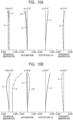
- the object side (front) is located on the left and the image side (rear) is located on the right.
- Li indicates an i-th lens unit where i denotes the number of lens unit arranged from the object side toward the image side.
- An aperture stop SP determines (limits) the light flux of an open F number (Fno). During focusing from an object at infinity to an object at the closest distance, focus lens units move as indicated by arrows in the drawings.
- an image plane IP corresponds to an image pickup element (photoelectric conversion element), such as a CCD sensor or a CMOS sensor.
- the image plane IP corresponds to a film surface.
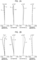
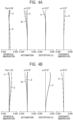
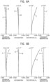
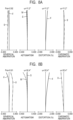
- FIGS. 2A, 2B , 4A, 4B , 6A, 6B , 8A, 8B , 10A and 10B are aberration diagrams of the optical systems according to the examples.
- Fno denotes an F number.
- a solid line indicates a d-line (a wavelength of 587.6 nm) and a chain double-dashed line indicates a g-line (a wavelength of 435.8 nm).
- a broken line M indicates a meridional image plane and a solid line S indicates a sagittal image plane.
- a distortion indicates that of the d-line.
- a lateral chromatic aberration indicates that of the g-line.
- ⁇ denotes a half angle of view (degree).
- lens unit may consist of a plurality of lenses or a single lens.
- Back focus is an air-equivalent distance from the final surface to the paraxial image plane of the optical system on an optical axis.
- Total lens length is determined by adding a back focus to a distance from the front surface to the final surface of the optical system on the optical axis.
- vd (Nd - 1)/(NF - NC)
- Ng, NF, Nd and NC are the refractive indexes of the material with respect to the g-line (a wavelength of 435.8 nm), the F-line (486.1 nm), the d-line (587.6 nm), and the C-line (656.3 nm), respectively.
- the optical systems according to the examples of the present invention each include a plurality of lens units in which intervals between adjacent lens units are changed during focusing.
- the plurality of lens units include a first lens unit that has positive refractive power and is disposed closest to the object side, a middle group including at least two lens units, and a final lens unit that has negative refractive power and is disposed closest to the image side.
- the middle group includes a first focus lens unit and a second focus lens unit that is disposed on the image side of the first focus lens unit both of which move during focusing.
- optical systems according to the examples of the present invention satisfy the following conditional expressions (1) and (2). ⁇ 7.00 ⁇ f/fn ⁇ ⁇ 1.78 1.10 ⁇ fr/fn ⁇ 5.50
- f denotes a focal length of the optical system
- fn denotes a focal length of the final lens unit
- fr denotes a focal length of the second focus lens unit.
- conditional expressions (1) and (2) are conditions for downsizing the optical system and achieving high optical performance over entire object distance by suppressing changes in aberration during focusing.
- the conditional expression (1) is a conditional expression of a focal length of the final lens unit.
- the final lens unit is set so as to have relatively high refractive power, thereby reducing a back focus and facilitating size reduction of the optical system.
- the ratio falls below the lower limit value in the conditional expression (1), the focal length of the final lens unit becomes shortened and the refractive power of the final lens unit becomes increased. Thus, it is difficult to correct various aberrations such as a field curvature and a distortion generated by the final lens unit, so that it is not preferable. If the ratio exceeds the upper limit value in the conditional expression (1), the focal length of the final lens unit becomes increased and the refractive power of the final lens unit becomes decreased. Thus, the back focus becomes increased and lead to difficulty in downsizing the optical system, so that it is not preferable.
- the conditional expression (2) is related to the ratio of the focal length of the final lens unit and the focal length of the second focus lens unit.
- the second focus lens unit is set to have refractive power properly lower than that of the final lens unit. This reduces the size of the optical system and suppresses changes in aberration during focusing.
- the ratio falls below the lower limit value in the conditional expression (2) to decrease the focal length of the second focus lens unit and increase the refractive power of the second focus lens unit, changes in aberration becomes increased during focusing, thus it is not preferable. If the ratio exceeds the upper limit value in the conditional expression (2) to increase the focal length of the second focus lens unit and to decrease the refractive power of the second focus lens unit, a moving amount becomes increased during focusing from an object at infinity to an object at the closest distance. This leads to difficulty in downsizing the optical system, thus it is not preferable.
- the optical system satisfies the above-described configurations and the conditional expressions (1) and (2) at the same time, thereby the optical system with a small size and high optical performance over entire object distance from an infinity to a closest distance can be obtained.
- the numerical ranges of the conditional expressions (1) and (2) may be set as follows: ⁇ 6.50 ⁇ f/fn ⁇ ⁇ 1.79 1.15 ⁇ fr/fn ⁇ 4.00
- the numerical ranges of the conditional expressions (1a) and (2a) may be set as follows: ⁇ 4.00 ⁇ f/fn ⁇ ⁇ 1.79 1.20 ⁇ fr/fn ⁇ 3.50
- the optical system according to the example satisfies conditional expression (3).
- the optical system according to the example may satisfy one or more of the conditional expressions (4) to (9).
- the effects of a size reduction of the optical system and a suppression of changes in aberration during focusing becomes enhanced and imaging (macro imaging) at a high imaging magnification becomes facilitated.
- sk denotes a back focus of the optical system during focusing on an object at infinity
- f1 denotes a focal length of the first lens unit
- f2 denotes a focal length of the second lens unit.
- the second lens unit is a lens unit that is disposed closest to the object side in the middle group and has positive or negative refractive power.
- the second lens unit corresponds to the first focus lens unit.
- the Abbe number with respect to the d-line of the material of a positive lens included in the second lens unit is denoted as vd2p.
- DL denotes the total lens length of the optical system during focusing on an object at infinity.
- D2 denotes a moving amount of the second lens unit during focusing from an object at infinity to an object at the closest distance when the second lens unit serves as the first focus lens unit
- Dr denotes a moving amount of the second focus lens unit during focusing from an object at infinity to an object at the closest distance.
- the signs of the moving amount D2 and the moving amount Dr become positive when the position of focusing on the object at the closest distance is closer to object side than the position of focusing on the object at infinity.
- the signs become negative when the position of focusing on the object at the closest distance is closer to the image side than the position of focusing on the object at infinity.
- ⁇ denotes an imaging magnification of the optical system during focusing on the object at the closest distance.
- the conditional expression (3) is a conditional expression related to the back focus of the optical system. If the ratio falls below the lower limit value in the conditional expression (3) to increase the back focus, it becomes difficult to downsize the optical system, thus it is not preferable. If the ratio exceeds the upper limit value in the conditional expression (3) to decrease the back focus of the optical system, the outer diameter of the lens closest to the image side becomes increased, thereby the size of the optical system becomes increased in a radial direction, thus it is not preferable.
- the conditional expression (4) is a conditional expression related to the focal length of the first lens unit. If the ratio falls below the lower limit value in the conditional expression (4) to increase the focal length of the first lens unit and decrease the refractive power of the first lens unit, the total lens length of the optical system becomes increased and leads to difficulty in downsizing, thus it is not preferable. If the ratio exceeds the upper limit value in the conditional expression (4) to decrease the focal length of the first lens unit and increase the refractive power of the first lens unit, various aberrations such as a spherical aberration occur, thus it is not preferable.
- conditional expressions (5) to (7) are related to the second lens unit disposed closest to the object side in the middle group and corresponding to the first focus lens unit that moves during focusing.
- the conditional expression (5) is a conditional expression related to the focal length of the second lens unit. If the ratio falls below the lower limit value in the conditional expression (5) to increase the focal length of the second lens unit and decrease the refractive power of the second lens unit, the moving amount of the second lens unit becomes increased during focusing from an object at infinity to an object at the closest distance. This leads to difficulty in downsizing the optical system, thus it is not preferable. If the ratio exceeds the upper limit value in the conditional expression (5) to decrease the focal length of the second lens unit and increase the refractive power of the second lens unit, changes in aberration during focusing becomes increased, thus it is not preferable.
- the conditional expression (6) is a conditional expression related to the Abbe number with respect to the d-line of the material of the positive lens included in the second lens unit. If the value falls below the lower limit value in the conditional expression (6), it becomes difficult to obtain a material satisfying the condition, thus it is not preferable. If the value exceeds the upper limit value in the conditional expression (6), unfortunately, it becomes difficult to suppress changes in chromatic aberration during focusing, thus it is not preferable.
- the conditional expression (7) properly sets a moving amount of the second lens unit during focusing from an object at infinity to an object at the closest distance. If the ratio falls below the lower limit value in the conditional expression (7) to decrease the moving amount of the second lens unit, the refractive power of the second lens unit becomes increased to obtain a predetermined imaging magnification, leading to difficulty in suppressing changes in aberration generated during focusing, thus it is not preferable. If the ratio exceeds the upper limit value in the conditional expression (7) to increase the moving amount of the second lens unit during focusing, the total lens length of the optical system becomes increased and leads to difficulty in downsizing, thus it is not preferable.
- the conditional expression (8) is related to the moving amount of the second focus lens unit during focusing from an object at infinity to an object at the closest distance. If the ratio falls below the lower limit value in the conditional expression (8) to decrease the moving amount of the second focus lens unit, the refractive power of the second focus lens unit becomes increased to obtain the predetermined imaging magnification, leading to difficulty in suppressing changes in aberration during focusing, thus it is not preferable. If the ratio exceeds the upper limit value in the conditional expression (8) to increase the moving amount of the second focus lens unit, the total lens length of the optical system becomes increased and leads to difficulty in downsizing, thus it is not preferable.
- conditional expression (9) is a conditional expression related to the imaging magnification of the optical system. If the value falls below the lower limit value in the conditional expression (9), it becomes difficult to sufficiently obtain the imaging effect of a macro lens, thus it is not preferable.
- the numerical ranges of the conditional expressions (4) to (9) may be set as follows: 1.30 ⁇ f / f1 ⁇ 3.50 1.80 ⁇ f / f2 ⁇ 5.00 10 ⁇ ⁇ d2p ⁇ 21 0.05 ⁇ D2 / DL ⁇ 0.30 0.05 ⁇ Dr / DL ⁇ 0.35 0.60 ⁇ ⁇ ⁇
- the numerical ranges of the conditional expressions (4a) to (9a) may be set as follows: 1.45 ⁇ f / f1 ⁇ 3.00 2.00 ⁇ f/ f2 ⁇ 4.50 10 ⁇ ⁇ d2p ⁇ 20 0.09 ⁇ D2 / DL ⁇ 0.27 0.10 ⁇ Dr / DL ⁇ 0.30 0.70 ⁇ ⁇ ⁇
- At least one of the first focus lens unit and the second focus lens unit consists of at most three lenses. This can easily reduce the weight of the focus lens unit, achieving high-speed focusing.
- the optical system according to the example of the present invention includes an aperture stop disposed in the middle group or between two lens units constituting the middle group. It is preferable that the aperture diameter of the aperture stop can be changed during focusing.
- the aperture diameter of the aperture stop is changed according to a change of Fno, thereby unnecessary light beams can be cut off.
- the aperture stop is disposed between the first focus lens unit and the second focus lens unit. Thereby, a diameter of the aperture stop can be decreased.
- the final lens unit includes a negative lens and a positive lens. Thereby, chromatic aberrations generated in the final lens unit can be corrected.
- the first lens unit does not move (is fixed) during focusing.
- the first lens unit that is likely to be heavier than other lens units can be immovable during focusing.
- high-speed focusing can be achieved.
- focusing on an object at a close distance can be performed at a short working distance, enabling close-distance imaging.
- a lens barrel can be configured to have high resistance to a pressure from outside.
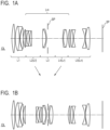
- FIG. 1A is a sectional view of an optical system OL according to Example 1 focusing on an object at infinity.
- FIG. 1B is a sectional view of the optical system OL according to Example 1 focusing on an object at the closest distance.
- FIG. 2A is an aberration diagram of the optical system OL according to Example 1 focusing on an object at infinity.
- FIG. 2B is an aberration diagram of the optical system OL according to Example 1 focusing on an object at the closest distance.
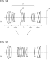
- FIG. 3A is a sectional view of the optical system OL according to Example 2 focusing on an object at infinity.
- FIG. 3B is a sectional view of the optical system OL according to Example 2 focusing on an object at the closest distance.
- FIG. 4A is an aberration diagram of the optical system OL according to Example 2 focusing on an object at infinity.
- FIG. 4B is an aberration diagram of the optical system OL according to Example 2 focusing on an object at the closest distance.
- the optical systems OL according to Examples 1 and 2 each consists of a first lens unit L1 having positive refractive power, a second lens unit L2 having negative refractive power, a third lens unit L3 having positive refractive power, a fourth lens unit L4 having positive refractive power and a fifth lens unit L5 serving as a final lens unit Ln having negative refractive power, disposed in order from the object side to the image side.
- a middle group Lm consists of the second lens unit L2, the third lens unit L3 and the fourth lens unit L4, and the third lens unit L3 includes an aperture stop SP.
- the second lens unit L2 serving as a first focus lens unit Lf moves toward the image side
- the fourth lens unit L4 serving as a second focus lens unit Lr moves toward the object side.
- Other lens units do not move during focusing.
- optical systems OL according to Examples 1 and 2 have basic lens unit configurations that are identical to each other. Lenses used in the optical systems are made of different materials and have different shapes.
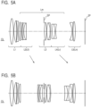
- FIG. 5A is a sectional view of an optical system OL according to Example 3 focusing on an object at infinity.
- FIG. 5B is a sectional view of the optical system OL according to Example 3 focusing on an object at the closest distance.
- FIG. 6A is an aberration diagram of the optical system OL according to Example 3 focusing on an object at infinity.
- FIG. 6B is an aberration diagram of the optical system OL according to Example 3 focusing on an object at the closest distance.
- the optical system OL according to Example 3 consists of a first lens unit L1 having positive refractive power, a second lens unit L2 having negative refractive power, a third lens unit L3 having positive refractive power, a fourth lens unit L4 having negative refractive power and a fifth lens unit L5 serving as a final lens unit Ln having negative refractive power, disposed in order from the object side to the image side.
- a middle group Lm consists of the second lens unit L2, the third lens unit L3 and the fourth lens unit L4, and the third lens unit L3 includes an aperture stop SP.
- the second lens unit L2 serving as a first focus lens unit Lf moves toward the image side
- the fourth lens unit L4 serving as a second focus lens unit Lr moves toward the image side.
- Other lens units do not move during focusing.
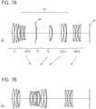
- FIG. 7A is a sectional view of an optical system OL according to Example 4 focusing on an object at infinity.
- FIG. 7B is a sectional view of the optical system OL according to Example 4 focusing on an object at the closest distance.
- FIG. 8A is an aberration diagram of the optical system OL according to Example 4 focusing on an object at infinity.
- FIG. 8B is an aberration diagram of the optical system OL according to Example 4 focusing on an object at the closest distance.
- the optical system OL according to Example 4 consists of a first lens unit L1 having positive refractive power, a second lens unit L2 having negative refractive power, a third lens unit L3 having positive refractive power, a fourth lens unit L4 having positive refractive power, a fifth lens unit L5 having positive refractive power and a sixth lens unit L6 serving as a final lens unit Ln having negative refractive power, disposed in order from the object side to the image side.
- a middle group Lm consists of the second lens unit L2, the third lens unit L3, the fourth lens unit L4 and the fifth lens unit L5, and the third lens unit L3 includes an aperture stop SP.
- the second lens unit L2 serving as a first focus lens unit Lf moves toward the image side
- the fifth lens unit L5 serving as a second focus lens unit Lr moves toward the object side.
- the fourth lens unit L4 moves toward the object side
- the sixth lens unit L6 moves toward to object side.
- Other lens units do not move during focusing.
- FIG. 9A is a sectional view of an optical system OL according to Example 5 focusing on an object at infinity.
- FIG. 9B is a sectional view of the optical system OL according to Example 5 focusing on an object at the closest distance.
- FIG. 10A is an aberration diagram of the optical system OL according to Example 5 focusing on an object at infinity.
- FIG. 10B is an aberration diagram of the optical system OL according to Example 5 focusing on an object at the closest distance.
- the optical system OL according to Example 5 consists of a first lens unit L1 having positive refractive power, a second lens unit L2 having negative refractive power, a third lens unit L3 having positive refractive power and a fourth lens unit L4 serving as a final lens unit Ln having negative refractive power, disposed in order from the object side to the image side.
- a middle group Lm consists of the second lens unit L2 and the third lens unit L3.
- An aperture stop SP not moving during focusing is disposed between the second lens unit L2 and the third lens unit L3.
- the second lens unit L2 serving as a first focus lens unit Lf moves toward the image side
- the third lens unit L3 serving as a second focus lens unit Lr moves toward the object side.
- Other lens units do not move during focusing.
- optical systems OL according to Examples 1 to 5 simultaneously satisfy the conditional expressions (1) to (9).
- the optical system has a compact configuration with high optical performance over entire object distance.
- Numerical examples 1 to 5 corresponding to Examples 1 to 5 will be described below.
- surface numbers indicate the order of optical surfaces from the object side.
- r denotes a curvature radius (mm) of the optical surface
- d denotes an interval (mm) between the adjacent optical surfaces
- nd denotes a refractive index of a material of an optical member at a d-line
- vd denotes an Abbe number of the material of the optical member with respect to the d line.
- the Abbe number is defined as has been discussed above.
- BF indicates a back focus. In numerical example 4, a back focus during focusing at infinity is described.
- aspheric surfaces are indicated by surface numbers with * on the right.
- X axis direction is defined as the X axis
- H axis a direction perpendicular to the optical axis
- H axis a travel direction of light is defined as positive
- R denotes a paraxial curvature radius
- K denotes a conic constant
- A4, A6, A8, A10 and A12 denote aspheric coefficients
- e-x of the aspheric coefficient means 10 -x .
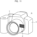
- FIG. 11 illustrates the configuration of an image pickup apparatus 10.
- the image pickup apparatus 10 includes a camera body 13, a lens apparatus 11 including the optical system OL according to Examples 3 or 4 described above, and a light receiving element (image pickup element) 12 that photoelectrically converts an image formed by the optical system OL.
- the light receiving element 12 may be an image pickup element, such as a CCD sensor or a CMOS sensor.
- the lens apparatus 11 and the camera body 13 may be integrated into each other or detachably attached to each other.
- the image pickup apparatus 10 of the present example can have a compact configuration with high optical performance over entire object distance.
- the image pickup apparatus 10 of the present invention is not limited to a digital still camera illustrated in FIG. 11 .
- the present invention is applicable to various image pickup apparatuses such as a broadcast camera, a silver film camera, and a surveillance camera.
- the signs of the focal lengths of the first focus lens unit and the second focus lens unit and the moving direction during focusing are not limited to those of the examples.
- the signs of the focal lengths and the moving direction can be changed as necessary according to the magnitude of the refractive powers of the first focus lens unit and second focus lens unit and the relationship between the refractive powers of the first and second focus lens units and other lens units.
- the aperture stop SP may move during focusing. If the third lens unit includes a plurality of lenses, the aperture stop SP may be disposed between two of the plurality of lenses.
- an image blur may be corrected by moving some of the lenses in a direction including components perpendicular to the optical axis.
Landscapes
- Physics & Mathematics (AREA)
- General Physics & Mathematics (AREA)
- Optics & Photonics (AREA)
- Nonlinear Science (AREA)
- Lenses (AREA)
Priority Applications (1)
| Application Number | Priority Date | Filing Date | Title |
|---|---|---|---|
| EP24166779.9A EP4386460A3 (en) | 2018-10-09 | 2019-10-02 | Optical system and image pickup apparatus |
Applications Claiming Priority (1)
| Application Number | Priority Date | Filing Date | Title |
|---|---|---|---|
| JP2018191202A JP7163126B2 (ja) | 2018-10-09 | 2018-10-09 | 光学系及び撮像装置 |
Related Child Applications (2)
| Application Number | Title | Priority Date | Filing Date |
|---|---|---|---|
| EP24166779.9A Division-Into EP4386460A3 (en) | 2018-10-09 | 2019-10-02 | Optical system and image pickup apparatus |
| EP24166779.9A Division EP4386460A3 (en) | 2018-10-09 | 2019-10-02 | Optical system and image pickup apparatus |
Publications (2)
| Publication Number | Publication Date |
|---|---|
| EP3637166A1 EP3637166A1 (en) | 2020-04-15 |
| EP3637166B1 true EP3637166B1 (en) | 2024-05-15 |
Family
ID=68136314
Family Applications (2)
| Application Number | Title | Priority Date | Filing Date |
|---|---|---|---|
| EP19201193.0A Active EP3637166B1 (en) | 2018-10-09 | 2019-10-02 | Optical system and image pickup apparatus |
| EP24166779.9A Pending EP4386460A3 (en) | 2018-10-09 | 2019-10-02 | Optical system and image pickup apparatus |
Family Applications After (1)
| Application Number | Title | Priority Date | Filing Date |
|---|---|---|---|
| EP24166779.9A Pending EP4386460A3 (en) | 2018-10-09 | 2019-10-02 | Optical system and image pickup apparatus |
Country Status (4)
| Country | Link |
|---|---|
| US (1) | US11256062B2 (enExample) |
| EP (2) | EP3637166B1 (enExample) |
| JP (1) | JP7163126B2 (enExample) |
| CN (2) | CN114706204B (enExample) |
Families Citing this family (5)
| Publication number | Priority date | Publication date | Assignee | Title |
|---|---|---|---|---|
| JP7494018B2 (ja) * | 2020-06-08 | 2024-06-03 | キヤノン株式会社 | 光学系およびそれを有する撮像装置 |
| JP7515321B2 (ja) * | 2020-07-08 | 2024-07-12 | 株式会社タムロン | 光学系及び撮像装置 |
| JP7521956B2 (ja) * | 2020-07-08 | 2024-07-24 | 株式会社タムロン | 光学系及び撮像装置 |
| WO2022097401A1 (ja) * | 2020-11-06 | 2022-05-12 | 株式会社ニコン | 光学系、光学機器、および光学系の製造方法 |
| CN116783532A (zh) * | 2021-02-15 | 2023-09-19 | 株式会社尼康 | 光学系统、光学设备及光学系统的制造方法 |
Family Cites Families (19)
| Publication number | Priority date | Publication date | Assignee | Title |
|---|---|---|---|---|
| US5179472A (en) * | 1990-06-25 | 1993-01-12 | Fuji Photo Optical Co., Ltd. | Zoom lens |
| JP3003081B2 (ja) * | 1990-08-31 | 2000-01-24 | 株式会社シグマ | インナーフォーカス式マクロレンズ |
| JP3476909B2 (ja) * | 1994-06-15 | 2003-12-10 | オリンパス株式会社 | 望遠レンズ |
| JP4590900B2 (ja) | 2004-03-30 | 2010-12-01 | 株式会社ニコン | 撮影レンズ |
| JP5125009B2 (ja) * | 2006-07-20 | 2013-01-23 | 株式会社ニコン | ズームレンズ、撮像装置、ズームレンズの防振方法、ズームレンズの変倍方法 |
| JP5489686B2 (ja) * | 2009-12-11 | 2014-05-14 | キヤノン株式会社 | ズームレンズ及びそれを有する撮像装置 |
| JP2012242742A (ja) | 2011-05-23 | 2012-12-10 | Canon Inc | 撮影光学系及びそれを有する撮像装置 |
| JP2014219601A (ja) | 2013-05-09 | 2014-11-20 | ソニー株式会社 | マクロレンズおよび撮像装置 |
| JP6251511B2 (ja) * | 2013-08-09 | 2017-12-20 | 株式会社タムロン | 光学系及び光学系のフォーカシング方法 |
| KR102066941B1 (ko) | 2013-12-16 | 2020-01-16 | 한화테크윈 주식회사 | 줌 렌즈계 |
| JP6344965B2 (ja) | 2014-05-08 | 2018-06-20 | キヤノン株式会社 | 光学系及びそれを有する撮像装置 |
| WO2016017725A1 (ja) | 2014-07-30 | 2016-02-04 | 株式会社ニコン | 変倍光学系、光学装置、変倍光学系の製造方法 |
| US10079964B2 (en) * | 2014-12-22 | 2018-09-18 | Panasonic Intellectual Property Management Co., Ltd. | Lens system, interchangeable lens apparatus, and camera system |
| WO2016136352A1 (ja) | 2015-02-26 | 2016-09-01 | ソニー株式会社 | マクロレンズおよび撮像装置 |
| JP6437901B2 (ja) | 2015-09-18 | 2018-12-12 | 富士フイルム株式会社 | ズームレンズおよび撮像装置 |
| JP6463261B2 (ja) | 2015-12-22 | 2019-01-30 | 株式会社タムロン | ズームレンズおよび撮像装置 |
| JP6559103B2 (ja) * | 2016-08-23 | 2019-08-14 | 富士フイルム株式会社 | 撮像レンズおよび撮像装置 |
| JP6559104B2 (ja) * | 2016-08-23 | 2019-08-14 | 富士フイルム株式会社 | 撮像レンズおよび撮像装置 |
| JP6771371B2 (ja) | 2016-12-12 | 2020-10-21 | 富士フイルム株式会社 | 撮像レンズおよび撮像装置 |
-
2018
- 2018-10-09 JP JP2018191202A patent/JP7163126B2/ja active Active
-
2019
- 2019-10-02 EP EP19201193.0A patent/EP3637166B1/en active Active
- 2019-10-02 US US16/590,671 patent/US11256062B2/en active Active
- 2019-10-02 EP EP24166779.9A patent/EP4386460A3/en active Pending
- 2019-10-09 CN CN202210365930.1A patent/CN114706204B/zh active Active
- 2019-10-09 CN CN201910954119.5A patent/CN111025611B/zh active Active
Also Published As
| Publication number | Publication date |
|---|---|
| US20200110242A1 (en) | 2020-04-09 |
| EP3637166A1 (en) | 2020-04-15 |
| CN111025611A (zh) | 2020-04-17 |
| CN111025611B (zh) | 2022-04-05 |
| CN114706204A (zh) | 2022-07-05 |
| JP7163126B2 (ja) | 2022-10-31 |
| US11256062B2 (en) | 2022-02-22 |
| EP4386460A2 (en) | 2024-06-19 |
| CN114706204B (zh) | 2024-08-23 |
| JP2020060660A (ja) | 2020-04-16 |
| EP4386460A3 (en) | 2024-08-28 |
Similar Documents
| Publication | Publication Date | Title |
|---|---|---|
| EP3637166B1 (en) | Optical system and image pickup apparatus | |
| EP2230546B1 (en) | Zoom lens system and image pickup apparatus including the same | |
| EP2650712B1 (en) | Zoom lens of the telephoto type having four lens groups | |
| JP6566646B2 (ja) | ズームレンズ及びそれを有する撮像装置 | |
| EP2927726B1 (en) | Zoom lens and image pickup apparatus including the same | |
| JP4959236B2 (ja) | 高変倍率ズームレンズ | |
| US7227700B2 (en) | Wide zoom lens system | |
| JP5473624B2 (ja) | ズームレンズ及びそれを有する撮像装置 | |
| JP5350129B2 (ja) | ズームレンズ及びそれを有する撮像装置 | |
| EP3647850B1 (en) | Zoom lens and image pickup apparatus including the same | |
| EP3767362B1 (en) | Optical system and optical apparatus | |
| EP3534197A1 (en) | Zoom lens and image pickup apparatus | |
| JP7289711B2 (ja) | 光学系及びそれを有する撮像装置 | |
| US9804372B2 (en) | Optical system and imaging apparatus including the same | |
| EP3702823B1 (en) | Zoom lens system and imaging device | |
| JP7263122B2 (ja) | ズームレンズおよび撮像装置 | |
| JP5584533B2 (ja) | ズームレンズおよびそれを有する撮像装置 | |
| JP7167000B2 (ja) | ズームレンズおよび撮像装置 | |
| EP2458419B1 (en) | Zoom lens system | |
| JP7146451B2 (ja) | ズームレンズ及び撮像装置 | |
| JP7399113B2 (ja) | 撮像レンズおよび撮像装置 | |
| JP6808441B2 (ja) | ズームレンズ及びそれを有する撮像装置 | |
| EP3093700B1 (en) | Zoom lens system | |
| JP7144383B2 (ja) | ズームレンズおよび撮像装置 | |
| EP3828613A1 (en) | Zoom lens and image capturing apparatus including the same |
Legal Events
| Date | Code | Title | Description |
|---|---|---|---|
| PUAI | Public reference made under article 153(3) epc to a published international application that has entered the european phase |
Free format text: ORIGINAL CODE: 0009012 |
|
| STAA | Information on the status of an ep patent application or granted ep patent |
Free format text: STATUS: THE APPLICATION HAS BEEN PUBLISHED |
|
| AK | Designated contracting states |
Kind code of ref document: A1 Designated state(s): AL AT BE BG CH CY CZ DE DK EE ES FI FR GB GR HR HU IE IS IT LI LT LU LV MC MK MT NL NO PL PT RO RS SE SI SK SM TR |
|
| AX | Request for extension of the european patent |
Extension state: BA ME |
|
| STAA | Information on the status of an ep patent application or granted ep patent |
Free format text: STATUS: REQUEST FOR EXAMINATION WAS MADE |
|
| 17P | Request for examination filed |
Effective date: 20201015 |
|
| RBV | Designated contracting states (corrected) |
Designated state(s): AL AT BE BG CH CY CZ DE DK EE ES FI FR GB GR HR HU IE IS IT LI LT LU LV MC MK MT NL NO PL PT RO RS SE SI SK SM TR |
|
| STAA | Information on the status of an ep patent application or granted ep patent |
Free format text: STATUS: EXAMINATION IS IN PROGRESS |
|
| 17Q | First examination report despatched |
Effective date: 20220429 |
|
| GRAP | Despatch of communication of intention to grant a patent |
Free format text: ORIGINAL CODE: EPIDOSNIGR1 |
|
| STAA | Information on the status of an ep patent application or granted ep patent |
Free format text: STATUS: GRANT OF PATENT IS INTENDED |
|
| INTG | Intention to grant announced |
Effective date: 20231205 |
|
| GRAS | Grant fee paid |
Free format text: ORIGINAL CODE: EPIDOSNIGR3 |
|
| GRAA | (expected) grant |
Free format text: ORIGINAL CODE: 0009210 |
|
| STAA | Information on the status of an ep patent application or granted ep patent |
Free format text: STATUS: THE PATENT HAS BEEN GRANTED |
|
| AK | Designated contracting states |
Kind code of ref document: B1 Designated state(s): AL AT BE BG CH CY CZ DE DK EE ES FI FR GB GR HR HU IE IS IT LI LT LU LV MC MK MT NL NO PL PT RO RS SE SI SK SM TR |
|
| REG | Reference to a national code |
Ref country code: CH Ref legal event code: EP |
|
| REG | Reference to a national code |
Ref country code: DE Ref legal event code: R096 Ref document number: 602019052186 Country of ref document: DE |
|
| REG | Reference to a national code |
Ref country code: IE Ref legal event code: FG4D |
|
| REG | Reference to a national code |
Ref country code: LT Ref legal event code: MG9D |
|
| REG | Reference to a national code |
Ref country code: NL Ref legal event code: MP Effective date: 20240515 |
|
| PG25 | Lapsed in a contracting state [announced via postgrant information from national office to epo] |
Ref country code: IS Free format text: LAPSE BECAUSE OF FAILURE TO SUBMIT A TRANSLATION OF THE DESCRIPTION OR TO PAY THE FEE WITHIN THE PRESCRIBED TIME-LIMIT Effective date: 20240915 |
|
| PG25 | Lapsed in a contracting state [announced via postgrant information from national office to epo] |
Ref country code: BG Free format text: LAPSE BECAUSE OF FAILURE TO SUBMIT A TRANSLATION OF THE DESCRIPTION OR TO PAY THE FEE WITHIN THE PRESCRIBED TIME-LIMIT Effective date: 20240515 |
|
| PG25 | Lapsed in a contracting state [announced via postgrant information from national office to epo] |
Ref country code: FI Free format text: LAPSE BECAUSE OF FAILURE TO SUBMIT A TRANSLATION OF THE DESCRIPTION OR TO PAY THE FEE WITHIN THE PRESCRIBED TIME-LIMIT Effective date: 20240515 Ref country code: HR Free format text: LAPSE BECAUSE OF FAILURE TO SUBMIT A TRANSLATION OF THE DESCRIPTION OR TO PAY THE FEE WITHIN THE PRESCRIBED TIME-LIMIT Effective date: 20240515 |
|
| PG25 | Lapsed in a contracting state [announced via postgrant information from national office to epo] |
Ref country code: GR Free format text: LAPSE BECAUSE OF FAILURE TO SUBMIT A TRANSLATION OF THE DESCRIPTION OR TO PAY THE FEE WITHIN THE PRESCRIBED TIME-LIMIT Effective date: 20240816 |
|
| PG25 | Lapsed in a contracting state [announced via postgrant information from national office to epo] |
Ref country code: PT Free format text: LAPSE BECAUSE OF FAILURE TO SUBMIT A TRANSLATION OF THE DESCRIPTION OR TO PAY THE FEE WITHIN THE PRESCRIBED TIME-LIMIT Effective date: 20240916 |
|
| REG | Reference to a national code |
Ref country code: AT Ref legal event code: MK05 Ref document number: 1687362 Country of ref document: AT Kind code of ref document: T Effective date: 20240515 |
|
| PG25 | Lapsed in a contracting state [announced via postgrant information from national office to epo] |
Ref country code: NL Free format text: LAPSE BECAUSE OF FAILURE TO SUBMIT A TRANSLATION OF THE DESCRIPTION OR TO PAY THE FEE WITHIN THE PRESCRIBED TIME-LIMIT Effective date: 20240515 |
|
| PG25 | Lapsed in a contracting state [announced via postgrant information from national office to epo] |
Ref country code: ES Free format text: LAPSE BECAUSE OF FAILURE TO SUBMIT A TRANSLATION OF THE DESCRIPTION OR TO PAY THE FEE WITHIN THE PRESCRIBED TIME-LIMIT Effective date: 20240515 |
|
| PG25 | Lapsed in a contracting state [announced via postgrant information from national office to epo] |
Ref country code: AT Free format text: LAPSE BECAUSE OF FAILURE TO SUBMIT A TRANSLATION OF THE DESCRIPTION OR TO PAY THE FEE WITHIN THE PRESCRIBED TIME-LIMIT Effective date: 20240515 |
|
| PG25 | Lapsed in a contracting state [announced via postgrant information from national office to epo] |
Ref country code: PL Free format text: LAPSE BECAUSE OF FAILURE TO SUBMIT A TRANSLATION OF THE DESCRIPTION OR TO PAY THE FEE WITHIN THE PRESCRIBED TIME-LIMIT Effective date: 20240515 |
|
| PG25 | Lapsed in a contracting state [announced via postgrant information from national office to epo] |
Ref country code: LV Free format text: LAPSE BECAUSE OF FAILURE TO SUBMIT A TRANSLATION OF THE DESCRIPTION OR TO PAY THE FEE WITHIN THE PRESCRIBED TIME-LIMIT Effective date: 20240515 |
|
| PG25 | Lapsed in a contracting state [announced via postgrant information from national office to epo] |
Ref country code: PT Free format text: LAPSE BECAUSE OF FAILURE TO SUBMIT A TRANSLATION OF THE DESCRIPTION OR TO PAY THE FEE WITHIN THE PRESCRIBED TIME-LIMIT Effective date: 20240916 Ref country code: PL Free format text: LAPSE BECAUSE OF FAILURE TO SUBMIT A TRANSLATION OF THE DESCRIPTION OR TO PAY THE FEE WITHIN THE PRESCRIBED TIME-LIMIT Effective date: 20240515 Ref country code: NO Free format text: LAPSE BECAUSE OF FAILURE TO SUBMIT A TRANSLATION OF THE DESCRIPTION OR TO PAY THE FEE WITHIN THE PRESCRIBED TIME-LIMIT Effective date: 20240815 Ref country code: NL Free format text: LAPSE BECAUSE OF FAILURE TO SUBMIT A TRANSLATION OF THE DESCRIPTION OR TO PAY THE FEE WITHIN THE PRESCRIBED TIME-LIMIT Effective date: 20240515 Ref country code: LV Free format text: LAPSE BECAUSE OF FAILURE TO SUBMIT A TRANSLATION OF THE DESCRIPTION OR TO PAY THE FEE WITHIN THE PRESCRIBED TIME-LIMIT Effective date: 20240515 Ref country code: IS Free format text: LAPSE BECAUSE OF FAILURE TO SUBMIT A TRANSLATION OF THE DESCRIPTION OR TO PAY THE FEE WITHIN THE PRESCRIBED TIME-LIMIT Effective date: 20240915 Ref country code: HR Free format text: LAPSE BECAUSE OF FAILURE TO SUBMIT A TRANSLATION OF THE DESCRIPTION OR TO PAY THE FEE WITHIN THE PRESCRIBED TIME-LIMIT Effective date: 20240515 Ref country code: GR Free format text: LAPSE BECAUSE OF FAILURE TO SUBMIT A TRANSLATION OF THE DESCRIPTION OR TO PAY THE FEE WITHIN THE PRESCRIBED TIME-LIMIT Effective date: 20240816 Ref country code: FI Free format text: LAPSE BECAUSE OF FAILURE TO SUBMIT A TRANSLATION OF THE DESCRIPTION OR TO PAY THE FEE WITHIN THE PRESCRIBED TIME-LIMIT Effective date: 20240515 Ref country code: ES Free format text: LAPSE BECAUSE OF FAILURE TO SUBMIT A TRANSLATION OF THE DESCRIPTION OR TO PAY THE FEE WITHIN THE PRESCRIBED TIME-LIMIT Effective date: 20240515 Ref country code: BG Free format text: LAPSE BECAUSE OF FAILURE TO SUBMIT A TRANSLATION OF THE DESCRIPTION OR TO PAY THE FEE WITHIN THE PRESCRIBED TIME-LIMIT Effective date: 20240515 Ref country code: AT Free format text: LAPSE BECAUSE OF FAILURE TO SUBMIT A TRANSLATION OF THE DESCRIPTION OR TO PAY THE FEE WITHIN THE PRESCRIBED TIME-LIMIT Effective date: 20240515 Ref country code: RS Free format text: LAPSE BECAUSE OF FAILURE TO SUBMIT A TRANSLATION OF THE DESCRIPTION OR TO PAY THE FEE WITHIN THE PRESCRIBED TIME-LIMIT Effective date: 20240815 |
|
| PGFP | Annual fee paid to national office [announced via postgrant information from national office to epo] |
Ref country code: DE Payment date: 20240919 Year of fee payment: 6 |
|
| PG25 | Lapsed in a contracting state [announced via postgrant information from national office to epo] |
Ref country code: DK Free format text: LAPSE BECAUSE OF FAILURE TO SUBMIT A TRANSLATION OF THE DESCRIPTION OR TO PAY THE FEE WITHIN THE PRESCRIBED TIME-LIMIT Effective date: 20240515 |
|
| PG25 | Lapsed in a contracting state [announced via postgrant information from national office to epo] |
Ref country code: EE Free format text: LAPSE BECAUSE OF FAILURE TO SUBMIT A TRANSLATION OF THE DESCRIPTION OR TO PAY THE FEE WITHIN THE PRESCRIBED TIME-LIMIT Effective date: 20240515 |
|
| PG25 | Lapsed in a contracting state [announced via postgrant information from national office to epo] |
Ref country code: CZ Free format text: LAPSE BECAUSE OF FAILURE TO SUBMIT A TRANSLATION OF THE DESCRIPTION OR TO PAY THE FEE WITHIN THE PRESCRIBED TIME-LIMIT Effective date: 20240515 |
|
| PG25 | Lapsed in a contracting state [announced via postgrant information from national office to epo] |
Ref country code: SK Free format text: LAPSE BECAUSE OF FAILURE TO SUBMIT A TRANSLATION OF THE DESCRIPTION OR TO PAY THE FEE WITHIN THE PRESCRIBED TIME-LIMIT Effective date: 20240515 Ref country code: RO Free format text: LAPSE BECAUSE OF FAILURE TO SUBMIT A TRANSLATION OF THE DESCRIPTION OR TO PAY THE FEE WITHIN THE PRESCRIBED TIME-LIMIT Effective date: 20240515 |
|
| PG25 | Lapsed in a contracting state [announced via postgrant information from national office to epo] |
Ref country code: SM Free format text: LAPSE BECAUSE OF FAILURE TO SUBMIT A TRANSLATION OF THE DESCRIPTION OR TO PAY THE FEE WITHIN THE PRESCRIBED TIME-LIMIT Effective date: 20240515 |
|
| PG25 | Lapsed in a contracting state [announced via postgrant information from national office to epo] |
Ref country code: SM Free format text: LAPSE BECAUSE OF FAILURE TO SUBMIT A TRANSLATION OF THE DESCRIPTION OR TO PAY THE FEE WITHIN THE PRESCRIBED TIME-LIMIT Effective date: 20240515 Ref country code: SK Free format text: LAPSE BECAUSE OF FAILURE TO SUBMIT A TRANSLATION OF THE DESCRIPTION OR TO PAY THE FEE WITHIN THE PRESCRIBED TIME-LIMIT Effective date: 20240515 Ref country code: RO Free format text: LAPSE BECAUSE OF FAILURE TO SUBMIT A TRANSLATION OF THE DESCRIPTION OR TO PAY THE FEE WITHIN THE PRESCRIBED TIME-LIMIT Effective date: 20240515 Ref country code: EE Free format text: LAPSE BECAUSE OF FAILURE TO SUBMIT A TRANSLATION OF THE DESCRIPTION OR TO PAY THE FEE WITHIN THE PRESCRIBED TIME-LIMIT Effective date: 20240515 Ref country code: DK Free format text: LAPSE BECAUSE OF FAILURE TO SUBMIT A TRANSLATION OF THE DESCRIPTION OR TO PAY THE FEE WITHIN THE PRESCRIBED TIME-LIMIT Effective date: 20240515 Ref country code: CZ Free format text: LAPSE BECAUSE OF FAILURE TO SUBMIT A TRANSLATION OF THE DESCRIPTION OR TO PAY THE FEE WITHIN THE PRESCRIBED TIME-LIMIT Effective date: 20240515 |
|
| PG25 | Lapsed in a contracting state [announced via postgrant information from national office to epo] |
Ref country code: IT Free format text: LAPSE BECAUSE OF FAILURE TO SUBMIT A TRANSLATION OF THE DESCRIPTION OR TO PAY THE FEE WITHIN THE PRESCRIBED TIME-LIMIT Effective date: 20240515 |
|
| REG | Reference to a national code |
Ref country code: DE Ref legal event code: R097 Ref document number: 602019052186 Country of ref document: DE |
|
| PLBE | No opposition filed within time limit |
Free format text: ORIGINAL CODE: 0009261 |
|
| STAA | Information on the status of an ep patent application or granted ep patent |
Free format text: STATUS: NO OPPOSITION FILED WITHIN TIME LIMIT |
|
| 26N | No opposition filed |
Effective date: 20250218 |
|
| PG25 | Lapsed in a contracting state [announced via postgrant information from national office to epo] |
Ref country code: SI Free format text: LAPSE BECAUSE OF FAILURE TO SUBMIT A TRANSLATION OF THE DESCRIPTION OR TO PAY THE FEE WITHIN THE PRESCRIBED TIME-LIMIT Effective date: 20240515 |
|
| REG | Reference to a national code |
Ref country code: CH Ref legal event code: PL |
|
| PG25 | Lapsed in a contracting state [announced via postgrant information from national office to epo] |
Ref country code: MC Free format text: LAPSE BECAUSE OF FAILURE TO SUBMIT A TRANSLATION OF THE DESCRIPTION OR TO PAY THE FEE WITHIN THE PRESCRIBED TIME-LIMIT Effective date: 20240515 |
|
| PG25 | Lapsed in a contracting state [announced via postgrant information from national office to epo] |
Ref country code: LU Free format text: LAPSE BECAUSE OF NON-PAYMENT OF DUE FEES Effective date: 20241002 Ref country code: BE Free format text: LAPSE BECAUSE OF NON-PAYMENT OF DUE FEES Effective date: 20241031 |
|
| PG25 | Lapsed in a contracting state [announced via postgrant information from national office to epo] |
Ref country code: FR Free format text: LAPSE BECAUSE OF NON-PAYMENT OF DUE FEES Effective date: 20241031 |
|
| PG25 | Lapsed in a contracting state [announced via postgrant information from national office to epo] |
Ref country code: CH Free format text: LAPSE BECAUSE OF NON-PAYMENT OF DUE FEES Effective date: 20241031 |
|
| REG | Reference to a national code |
Ref country code: BE Ref legal event code: MM Effective date: 20241031 |
|
| PG25 | Lapsed in a contracting state [announced via postgrant information from national office to epo] |
Ref country code: SE Free format text: LAPSE BECAUSE OF FAILURE TO SUBMIT A TRANSLATION OF THE DESCRIPTION OR TO PAY THE FEE WITHIN THE PRESCRIBED TIME-LIMIT Effective date: 20240515 |
|
| PGFP | Annual fee paid to national office [announced via postgrant information from national office to epo] |
Ref country code: GB Payment date: 20250923 Year of fee payment: 7 |
|
| PG25 | Lapsed in a contracting state [announced via postgrant information from national office to epo] |
Ref country code: IE Free format text: LAPSE BECAUSE OF NON-PAYMENT OF DUE FEES Effective date: 20241002 |