EP3637063B1 - Standardised capsule-type meter with an ultrasound measurement cell - Google Patents
Standardised capsule-type meter with an ultrasound measurement cell Download PDFInfo
- Publication number
- EP3637063B1 EP3637063B1 EP19200935.5A EP19200935A EP3637063B1 EP 3637063 B1 EP3637063 B1 EP 3637063B1 EP 19200935 A EP19200935 A EP 19200935A EP 3637063 B1 EP3637063 B1 EP 3637063B1
- Authority
- EP
- European Patent Office
- Prior art keywords
- channel
- inlet
- adapter
- outlet
- measurement
- Prior art date
- Legal status (The legal status is an assumption and is not a legal conclusion. Google has not performed a legal analysis and makes no representation as to the accuracy of the status listed.)
- Active
Links
- 238000005259 measurement Methods 0.000 title claims description 43
- 238000002604 ultrasonography Methods 0.000 title description 3
- 239000002775 capsule Substances 0.000 claims description 7
- 230000006978 adaptation Effects 0.000 description 18
- 239000012530 fluid Substances 0.000 description 8
- 230000013707 sensory perception of sound Effects 0.000 description 6
- XLYOFNOQVPJJNP-UHFFFAOYSA-N water Substances O XLYOFNOQVPJJNP-UHFFFAOYSA-N 0.000 description 5
- 238000005516 engineering process Methods 0.000 description 2
- 238000000465 moulding Methods 0.000 description 2
- 230000000750 progressive effect Effects 0.000 description 2
- 210000002105 tongue Anatomy 0.000 description 2
- 238000009434 installation Methods 0.000 description 1
- 238000004519 manufacturing process Methods 0.000 description 1
- 238000000034 method Methods 0.000 description 1
- 230000002093 peripheral effect Effects 0.000 description 1
- 230000001681 protective effect Effects 0.000 description 1
- 238000003466 welding Methods 0.000 description 1
Images


Classifications
-
- G—PHYSICS
- G01—MEASURING; TESTING
- G01F—MEASURING VOLUME, VOLUME FLOW, MASS FLOW OR LIQUID LEVEL; METERING BY VOLUME
- G01F1/00—Measuring the volume flow or mass flow of fluid or fluent solid material wherein the fluid passes through a meter in a continuous flow
- G01F1/66—Measuring the volume flow or mass flow of fluid or fluent solid material wherein the fluid passes through a meter in a continuous flow by measuring frequency, phase shift or propagation time of electromagnetic or other waves, e.g. using ultrasonic flowmeters
- G01F1/662—Constructional details
-
- G—PHYSICS
- G01—MEASURING; TESTING
- G01F—MEASURING VOLUME, VOLUME FLOW, MASS FLOW OR LIQUID LEVEL; METERING BY VOLUME
- G01F15/00—Details of, or accessories for, apparatus of groups G01F1/00 - G01F13/00 insofar as such details or appliances are not adapted to particular types of such apparatus
-
- G—PHYSICS
- G01—MEASURING; TESTING
- G01F—MEASURING VOLUME, VOLUME FLOW, MASS FLOW OR LIQUID LEVEL; METERING BY VOLUME
- G01F15/00—Details of, or accessories for, apparatus of groups G01F1/00 - G01F13/00 insofar as such details or appliances are not adapted to particular types of such apparatus
- G01F15/18—Supports or connecting means for meters
- G01F15/185—Connecting means, e.g. bypass conduits
-
- G—PHYSICS
- G01—MEASURING; TESTING
- G01F—MEASURING VOLUME, VOLUME FLOW, MASS FLOW OR LIQUID LEVEL; METERING BY VOLUME
- G01F15/00—Details of, or accessories for, apparatus of groups G01F1/00 - G01F13/00 insofar as such details or appliances are not adapted to particular types of such apparatus
- G01F15/14—Casings, e.g. of special material
Definitions
- the invention relates to a capsule-type ultrasonic measuring cell counter.
- a fluid meter in particular water, comprising an ultrasonic measurement cell, of the capsule type, comprising a measurement channel equipped with ultrasonic sensors and mounted on a tarpaulin comprising a pipe inlet and an outlet conduit, said inlet conduit communicating with the inlet of the measurement channel and said outlet conduit communicating with the outlet of the measurement channel.
- JP 2005 189090 describes an ultrasonic water meter to reduce the space to be attached to a water pipe while ensuring the propagation distance of ultrasonic waves.
- a flowmeter in particular a measurement capsule, comprising an antechamber disposed inside a housing to introduce a fluid into a measurement zone.
- EWG-Bauartzu vibr vom 15.12.1992 is an EEC type approval certificate for a multi-jet turbine meter for hot water.
- a capsule-type measuring cell means a removable measuring cell which can be mounted on a tarpaulin and removed from a tarpaulin, without intervening on the installation of the latter, i.e. i.e. without the need to disassemble and reassemble the tarpaulin.
- the first type of cover is of the coaxial type, that is to say that the outlet pipe has an elbow so as to emerge in a centered manner on the central axis of the cover and the inlet pipe opens through an orifice on a coaxial annular volume.
- the second type of tarpaulin of the aligned type comprises a rectilinear and aligned inlet duct and an outlet duct opening directly into the interior of the tarp.
- Such a counter is described in the patent document WO 2008/107375 which describes a meter with a capsule-type ultrasonic measuring cell, comprising a standardized measuring cell which can be installed on a tarpaulin of the first type or of the second type.
- the method of mounting an ultrasonic measurement cell, of the capsule type consists in using an additional adaptation piece, specific to the type of tank and connecting the inlet pipe with the inlet of the channel channel and the output line with the output of the measuring channel.
- the adapter piece consists of a bent tubular piece 5 intended to be mounted on the mouth of the inlet pipe 3A and to be connected in a sealed manner to the measuring cell 1.
- FIG. 1 illustrates by arrows, the flow of the fluid.
- the latter arrives via the inlet pipe 3A of the cover, inside the adaptation part 5. It then travels through an admission channel 1H to reach the measurement channel 1A from where it is evacuated by a discharge channel 1I to the inside of the tank 3, from where it flows into the outlet pipe 3B of the tank.
- the invention proposes an adaptation part for mounting an ultrasound measurement cell, of the capsule type, comprising a measurement channel equipped with ultrasound sensors. sounds and intended to be mounted on a tarpaulin comprising an inlet duct and an outlet duct of the aligned type, the inlet duct and the rectilinear and aligned outlet duct of which open directly into the interior of the tarpaulin, this part additional adapter connecting said inlet pipe with the inlet of said measurement channel and said outlet pipe with the outlet of said measurement channel and comprising a bent tubular channel intended to be connected to the mouth of one of said pipes, part characterized in that it comprises a second bent tubular channel intended to be connected to the mouth of the other of said pipes.
- said bent channels are curved channels of perfectly progressive shape, with at one of their ends a circular section corresponding to and close to the section of the inlet and outlet pipes of the tarpaulin and at the other of their ends an oblong section corresponding to and close to the section of the inlet and outlet openings of the measurement cell, this circular section being greater than this oblong section.
- this piece consists of a single piece pierced with said two bent channels.
- edges of said bent channels have a circular undercut.
- this part comprises an O-ring placed in a groove surrounding the outlet or the inlet of one of said channels elbows of the adapter piece and an O-ring placed in a groove surrounding the inlet or the outlet of this same channel of the adapter piece.
- the adapter piece may include a snap arrangement intended to cooperate with corresponding means carried by the measurement cell.
- It may also comprise at least one positioning pin intended to be inserted into an orifice provided in the measuring cell.
- the invention also relates to a so-called capsule assembly consisting of a measuring cell and an adaptation part as specified above, assembled.
- the ultrasonic measurement cell 1 comprises a measurement channel 1A equipped with an ultrasonic transmitter and receiver sensor 1B at each of its ends.
- a protective cover 1G is arranged at the top.
- the input pipe of the tank 3A is intended to communicate with the input of the measurement channel corresponding to the input hearing 1E and the output pipe of the tank 3B is intended to communicate with the output of the measurement channel corresponding to the 1F output hearing.
- the adapter part 6 arranged at the level of the tank is connected to the pipes of the tank, this adapter part ensuring a flow of fluid in the measurement channel 1A of the measurement cell.
- the adaptation part 6 comprises a first tubular channel 6A bent at 90° intended to be mounted on the mouth of the inlet pipe 3A of the cover and to be connected in a sealed manner to the inlet hearing 1E of the plate 1C of the measuring cell.
- it also comprises a second tubular channel 6B bent at 90° intended to be connected to the mouth of the outlet pipe 3B of the cover and to be connected in a sealed manner to the outlet hearing 1F of the plate 1C of the measuring cell.
- the adaptation piece 6 is therefore a single piece adapted to the shape and size of the tarpaulin, pierced with these channels.
- An O-ring 7A is placed in a groove surrounding the outlet of the second bent channel 6B of the adapter part. It is intended to be compressed against the latter and the cover around the outlet pipe 3B of the latter.
- An O-ring 7B is placed in a groove surrounding the entrance to the second bent channel 6B of the adapter piece. He is intended to be compressed against the latter and the plate 1C around the outlet hearing 1F of the measuring cell.
- these seals can be arranged on the first bent channel 6A, the first in a groove surrounding the inlet of the first bent channel 6A and the second in a groove surrounding the outlet of the first bent channel 6A.
- the adapter piece 6 comprises on its upper face at least one positioning pin 8, preferably two pins, intended to be inserted into a corresponding orifice provided in the plate 1C of the measuring cell, in order to ensure precise positioning of the hearings 1E and 1F of the measuring cell opposite the angled channels 6A, 6B of the adaptation part.
- peripheral tongues 9 carried by the adaptation part 6 and introduced into a notch formed in the plate 1C of the measuring cell, these tongues also ensuring a snap-fastening of these two elements.
- the measuring cell 1 is secured to the adaptation piece 6 by inserting the pin 8 and snapping the tabs 9 into the corresponding cavities of the measuring cell.
- measurement cell 1 and adaptation part 6 are fixed to the cover 3 by screwing the clamping ring 1D of the measurement cell onto the internal thread 3C carried by the cover. This screwing ensures the tightening of the adaptation piece 6 against the periphery of the mouth of the inlet and outlet pipes 3A, 3B of the cover with the interposition of the seal 7A provided on the adaptation piece as well as the clamping of the adaptation piece 6 against the plate 1C of the measuring cell with the interposition of the seal 7B provided on the adaptation piece.
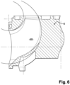
- the bent channels 6A, 6B of the adaptation part are curved channels of perfectly progressive shape, as illustrated in the figure 5 , provided at one of their ends with a circular section S 1 corresponding to and close to the section of the inlet and outlet pipes 2A, 2B of the cover and at the other of their ends an oblong section S 2 corresponding to and close to the section of the inlet and outlet openings 1E, 1F of the measuring cell, this circular section being greater than this oblong section.
- the adapter piece 6 can consist of several parts assembled for example by welding, the bent channels then not necessarily being provided with a circular undercut.
Description
L'invention concerne un compteur à cellule de mesure à ultra son de type capsule.The invention relates to a capsule-type ultrasonic measuring cell counter.
Elle se rapporte plus précisément à un compteur de fluide, en particulier d'eau, comportant une cellule de mesure à ultra sons, de type capsule, comportant un canal de mesure équipé de capteurs d'ultra sons et montée sur une bâche comportant une conduite d'entrée et une conduite de sortie, ladite conduite d'entrée communiquant avec l'entrée du canal de mesure et ladite conduite de sortie communiquant avec la sortie du canal de mesure.It relates more specifically to a fluid meter, in particular water, comprising an ultrasonic measurement cell, of the capsule type, comprising a measurement channel equipped with ultrasonic sensors and mounted on a tarpaulin comprising a pipe inlet and an outlet conduit, said inlet conduit communicating with the inlet of the measurement channel and said outlet conduit communicating with the outlet of the measurement channel.
"EWG-Bauartzulassung vom 15.12.1992" est un certificat d'homologation de type CEE pour un compteur à turbine multi-jets pour eau chaude."EWG-Bauartzulassung vom 15.12.1992" is an EEC type approval certificate for a multi-jet turbine meter for hot water.
Dans ce qui précède et dans ce qui suit, une cellule de mesure de type capsule signifie une cellule de mesure amovible qui peut être montée sur une bâche et démontée d'une bâche, sans intervenir sur l'installation de cette dernière, c'est-à-dire sans nécessité de démontage et remontage de la bâche.In the foregoing and in the following, a capsule-type measuring cell means a removable measuring cell which can be mounted on a tarpaulin and removed from a tarpaulin, without intervening on the installation of the latter, i.e. i.e. without the need to disassemble and reassemble the tarpaulin.
Il existe deux types de bâches. Le premier type de bâche est de type coaxial, c'est-à-dire que la conduite de sortie présente un coude de façon à déboucher de façon centrée sur l'axe central de la bâche et la conduite d'entrée débouche par un orifice sur un volume annulaire coaxial. Le second type de bâche de type aligné comporte une conduite d'entrée et une conduite de sortie rectilignes et alignées débouchant directement dans l'intérieur de la bâche.There are two types of tarps. The first type of cover is of the coaxial type, that is to say that the outlet pipe has an elbow so as to emerge in a centered manner on the central axis of the cover and the inlet pipe opens through an orifice on a coaxial annular volume. The second type of tarpaulin of the aligned type comprises a rectilinear and aligned inlet duct and an outlet duct opening directly into the interior of the tarp.
Un tel compteur est décrit dans le document de brevet
Selon ce document, le procédé de montage d'une cellule de mesure à ultra sons, de type capsule, consiste à utiliser une pièce d'adaptation supplémentaire, spécifique au type de bâche et raccordant la conduite d'entrée avec l'entrée du canal de mesure et la conduite de sortie avec la sortie du canal de mesure.According to this document, the method of mounting an ultrasonic measurement cell, of the capsule type, consists in using an additional adaptation piece, specific to the type of tank and connecting the inlet pipe with the inlet of the channel channel and the output line with the output of the measuring channel.
Selon un second mode de réalisation destiné à une bâche de type aligné, tel qu'illustré sur la
La
Il s'avère que ce mode de réalisation pose le problème technique suivant.It turns out that this embodiment poses the following technical problem.
En sortie du canal de refoulement 1I en aval du canal de mesure, le fluide s'écoule dans l'espace interne de la bâche non occupé par la pièce d'adaptation 5. Cet espace est de grand volume et l'évasement brusque de la veine de fluide entraîne la création de pertes de charge très importantes. Ces pertes de charge constituent un inconvénient majeur compliquant la conception et la mise au point du compteur, puisque ces pertes de charge contribuent à la perte de charge globale du compteur qui ne doit pas dépasser, au débit nominal, une valeur normalisée.At the outlet of the discharge channel 1I downstream of the measurement channel, the fluid flows into the internal space of the cover not occupied by the
Pour résoudre ce problème, l'invention propose une pièce d'adaptation pour le montage d'une cellule de mesure à ultra sons, de type capsule, comportant un canal de mesure équipé de capteurs d'ultra sons et destinée à être montée sur une bâche comportant une conduite d'entrée et une conduite de sortie de type aligné, dont la conduite d'entrée et la conduite de sortie rectilignes et alignées débouchent directement dans l'intérieur de la bâche, cette pièce d'adaptation supplémentaire raccordant ladite conduite d'entrée avec l'entrée du dit canal de mesure et ladite conduite de sortie avec la sortie du dit canal de mesure et comportant un canal tubulaire coudé destiné à être raccordé à l'embouchure de l'une desdites conduites, pièce caractérisée en ce qu'elle comporte un second canal tubulaire coudé destiné à être raccordé à l'embouchure de l'autre desdites conduites.To solve this problem, the invention proposes an adaptation part for mounting an ultrasound measurement cell, of the capsule type, comprising a measurement channel equipped with ultrasound sensors. sounds and intended to be mounted on a tarpaulin comprising an inlet duct and an outlet duct of the aligned type, the inlet duct and the rectilinear and aligned outlet duct of which open directly into the interior of the tarpaulin, this part additional adapter connecting said inlet pipe with the inlet of said measurement channel and said outlet pipe with the outlet of said measurement channel and comprising a bent tubular channel intended to be connected to the mouth of one of said pipes, part characterized in that it comprises a second bent tubular channel intended to be connected to the mouth of the other of said pipes.
Selon un mode de réalisation préféré, lesdits canaux coudés sont des canaux courbes de forme parfaitement progressive, avec à une de leurs extrémités une section circulaire correspondante à et proche de la section des conduites d'entrée et de sortie de la bâche et à l'autre de leurs extrémités une section oblongue correspondante à et proche de la section des ouïes d'entrée et de sortie de la cellule de mesure, cette section circulaire étant supérieure à cette section oblongue.According to a preferred embodiment, said bent channels are curved channels of perfectly progressive shape, with at one of their ends a circular section corresponding to and close to the section of the inlet and outlet pipes of the tarpaulin and at the other of their ends an oblong section corresponding to and close to the section of the inlet and outlet openings of the measurement cell, this circular section being greater than this oblong section.
Ainsi, le changement de direction de la veine de fluide, en particulier d'eau, dans la pièce d'adaptation, ne se fait pas de façon brusque comme décrit dans le document
De préférence, cette pièce est constituée d'une seule pièce percée desdits deux canaux coudés.Preferably, this piece consists of a single piece pierced with said two bent channels.
Avantageusement, les bords desdits canaux coudés présentent une dépouille circulaire.Advantageously, the edges of said bent channels have a circular undercut.
Ces canaux peuvent ainsi être réalisés lors du moulage par des noyaux rotatifs, ce qui permet leur moulage en une seule opération, sans faire appel à la technologie de moule à noyau perdu.These channels can thus be made during molding by rotating cores, which allows them to be molded in a single operation, without having to resort to lost-core mold technology.
De préférence, cette pièce comporte un joint torique disposé dans une rainure entourant la sortie ou l'entrée d'un desdits canaux coudés de la pièce d'adaptation et un joint torique disposé dans une rainure entourant l'entrée ou la sortie de ce même canal de la pièce d'adaptation.Preferably, this part comprises an O-ring placed in a groove surrounding the outlet or the inlet of one of said channels elbows of the adapter piece and an O-ring placed in a groove surrounding the inlet or the outlet of this same channel of the adapter piece.
La pièce d'adaptation peut comporter un agencement d'encliquetage destiné à coopérer avec des moyens correspondants portés par la cellule de mesure.The adapter piece may include a snap arrangement intended to cooperate with corresponding means carried by the measurement cell.
Elle peut également comporter au moins un pion de positionnement destiné à être inséré dans un orifice prévu dans la cellule de mesure.It may also comprise at least one positioning pin intended to be inserted into an orifice provided in the measuring cell.
L'invention concerne également un ensemble dit capsule constitué d'une cellule de mesure et d'une pièce d'adaptation telle que précisée ci-dessus, assemblées.The invention also relates to a so-called capsule assembly consisting of a measuring cell and an adaptation part as specified above, assembled.
L'invention est décrite ci-après plus en détail à l'aide de figures illustrant uniquement un mode de réalisation préféré de l'invention.
- La
figure 1 déjà évoquée représente en coupe verticale un compteur selon l'art antérieur. - La
figure 2 est une vue en perspective éclatée et en coupe verticale d'un compteur selon l'invention. - La
figure 3 est une vue en perspective en coupe verticale d'un compteur selon l'invention. - La
figure 4 est une vue partielle en coupe verticale d'un compteur selon l'invention. - La
figure 5 est une vue partielle en perspective du volume occupé par le fluide dans un des canaux coudés d'un compteur selon l'invention. - La
figure 6 est une vue de détail en coupe verticale d'un des canaux coudés d'un compteur selon l'invention.
- There
figure 1 already mentioned represents in vertical section a counter according to the prior art. - There
figure 2 is an exploded perspective view in vertical section of a counter according to the invention. - There
picture 3 - There
figure 4 is a partial view in vertical section of a counter according to the invention. - There
figure 5 is a partial perspective view of the volume occupied by the fluid in one of the bent channels of a meter according to the invention. - There
figure 6 is a detail view in vertical section of one of the angled channels of a meter according to the invention.
Comme représenté sur les
Elle comporte un plateau 1C portant le canal de mesure et une bague de serrage 1D, ce plateau comportant une ouïe d'entrée 1E et une ouïe de sortie 1F, la pièce d'adaptation 6 étant destinée à être connectée de façon étanche à ces ouïes. Un capot 1G de protection est disposé en partie supérieure.It comprises a
La conduite d'entrée de la bâche 3A est destinée à communiquer avec l'entrée du canal de mesure correspondant à l'ouïe d'entrée 1E et la conduite de sortie de la bâche 3B est destinée à communiquer avec la sortie du canal de mesure correspondant à l'ouïe de sortie 1F. La pièce d'adaptation 6 disposée au niveau de la bâche est raccordée aux conduites de la bâche, cette pièce d'adaptation assurant un écoulement de fluide dans le canal de mesure 1A de la cellule de mesure.The input pipe of the
La pièce d'adaptation 6 comporte un premier canal 6A tubulaire coudé à 90° destinée à être montée sur l'embouchure de la conduite d'entrée 3A de la bâche et à être reliée de façon étanche à l'ouïe d'entrée 1E du plateau 1C de la cellule de mesure.The
Selon l'invention, elle comporte également un second canal 6B tubulaire coudé à 90° destiné à être raccordé à l'embouchure de la conduite de sortie 3B de la bâche et à être reliée de façon étanche à l'ouïe de sortie 1F du plateau 1C de la cellule de mesure.According to the invention, it also comprises a second
La pièce d'adaptation 6 est donc d'une seule pièce adaptée à la forme et la dimension de la bâche, percée de ces canaux.The
Elle est équipée de joints d'étanchéité assurant l'étanchéité aux interfaces entre bâche 3, pièce d'adaptation 6 et cellule de mesure 1.It is equipped with seals ensuring tightness at the interfaces between
Un joint torique 7A est disposé dans une rainure entourant la sortie du second canal coudé 6B de la pièce d'adaptation. Il est destiné à être comprimé contre celle-ci et la bâche autour de la conduite de sortie 3B de cette dernière.An O-
Un joint torique 7B est disposé dans une rainure entourant l'entrée du second canal coudé 6B de la pièce d'adaptation. Il est destiné à être comprimé contre celle-ci et le plateau 1C autour de l'ouïe de sortie 1F de la cellule de mesure.An O-
En variante, de manière analogue, ces joints peuvent être disposés sur le premier canal coudé 6A, le premier dans une rainure entourant l'entrée du premier canal coudé 6A et le second dans une rainure entourant la sortie du premier canal coudé 6A.As a variant, in a similar way, these seals can be arranged on the
Par ailleurs, la pièce d'adaptation 6 comporte sur sa face supérieure au moins un pion 8 de positionnement, de préférence deux pions, destiné à être inséré dans un orifice correspondant prévu dans le plateau 1C de la cellule de mesure, afin d'assurer un positionnement précis des ouïes 1E et 1F de la cellule de mesure en face des canaux coudés 6A, 6B de la pièce d'adaptation.Furthermore, the
A cette liaison en rotation, s'ajoute une liaison en translation grâce à des languettes périphériques 9 portées par la pièce d'adaptation 6 et introduites dans un cran formé dans le plateau 1C de la cellule de mesure, ces languettes assurant également un encliquetage de ces deux éléments.In addition to this rotational connection, there is a translational connection thanks to
Pour leur montage, tout d'abord, la cellule de mesure 1 est solidarisée à la pièce d'adaptation 6 par insertion du pion 8 et encliquetage des languettes 9 dans les cavités correspondants de la cellule de mesure. Formant ainsi un sous-ensemble appelé capsule, cellule de mesure 1 et pièce d'adaptation 6 sont fixées à la bâche 3 par vissage de la bague de serrage 1D de la cellule de mesure sur le filetage intérieur 3C porté par la bâche. Ce vissage assure le serrage de la pièce d'adaptation 6 contre la périphérie de l'embouchure des conduites d'entrée et de sortie 3A, 3B de la bâche avec interposition du joint d'étanchéité 7A prévu sur la pièce d'adaptation ainsi que le serrage de la pièce d'adaptation 6 contre le plateau 1C de la cellule de mesure avec interposition du joint d'étanchéité 7B prévu sur la pièce d'adaptation.For their assembly, first of all, the
Les canaux coudés 6A, 6B de la pièce d'adaptation sont des canaux courbes de forme parfaitement progressive, comme illustré sur la
Par ailleurs, leur forme en section longitudinale verticale est représentée sur la
En variante, toujours dans le cadre de l'invention, la pièce d'adaptation 6 peut être constituée de plusieurs parties assemblées par exemple par soudure, les canaux coudés n'étant alors pas forcément dotés d'une dépouille circulaire.As a variant, still within the scope of the invention, the
Claims (15)
- Adapter (6) for mounting a capsule-type ultrasonic measurement cell (1), having a measurement channel (1A) equipped with ultrasonic sensors (1B), intended to be mounted on a tank (3) having an inlet pipe (3A) and an outlet pipe (3B) of aligned type, wherein the rectilinear and aligned inlet pipe and outlet pipe lead directly into the interior of the tank, this additional adapter (6) connecting said inlet pipe (3A) to the inlet of said measurement channel (1A) and said outlet pipe (3B) to the outlet of said measurement channel (1A), and having:a first bent tubular channel (6A) intended to be connected to the mouth of one of said pipes and to the inlet of said measurement channel, anda second bent tubular channel (6B) intended to be connected to the mouth of the other of said pipes and to the outlet of said measurement channel.
- Adapter according to the preceding claim, wherein said bent channels (6A, 6B) are curved channels with, at one of their ends, a circular section (S1) corresponding to and close to the section of the inlet and outlet pipes (3A, 3B) of the tank and, at the other of their ends, an oblong section (S2) corresponding to and close to the section of the inlet and outlet orifices (1E, 1F) of the measurement cell, this circular section being greater than this oblong section.
- Adapter according to either of the preceding claims, which is made up of a single piece pierced by said two bent channels (6A, 6B).
- Adapter according to the preceding claim, wherein the edges of said bent channels have a circular clearance.
- Adapter according to one of the preceding claims, which has an O-ring (7A) disposed in a groove surrounding the outlet of one of said bent channels (6A, 6B) of the adapter and an O-ring (7B) disposed in a groove surrounding the inlet of this same channel (6A, 6B) of the adapter.
- Adapter according to one of the preceding claims, which has a snap-fastening arrangement (9) intended to cooperate with corresponding means carried by the measurement cell (1).
- Adapter according to one of the preceding claims, which has at least one positioning pin (8) intended to be inserted into an orifice provided in the measurement cell (1).
- Adapter according to one of the preceding claims, wherein said measurement cell has an inlet orifice (1E) and an outlet orifice (1F), said adapter (6) being intended to be connected to these orifices (1E, 1F) in a leaktight manner.
- Adapter according to the preceding claim, wherein said first bent tubular channel (6A) is intended to be mounted on the mouth of said inlet pipe (3A) and to be connected to said inlet orifice (1E) in a leaktight manner.
- Adapter according to either of Claims 8 and 9, wherein said second bent tubular channel (6B) is intended to be connected to the mouth of said outlet pipe (3B) and to be connected to said outlet orifice (1F) in a leaktight manner.
- Assembly known as a capsule made up of an ultrasonic measurement cell (1) and of an adapter (6) according to one of the preceding claims, in an assembled state.
- Assembly according to Claim 11, the adapter being according to one of Claims 8 to 10, wherein the section of said inlet orifice (1E) and the section of said outlet pipe (3B) are oblong.
- Assembly according to either of Claims 11 and 12, wherein said inlet pipe (3A) is connected to the inlet of said measurement channel (1A) via the first bent tubular channel (6A) and an intake channel (1H) disposed at one end of said measurement channel (1A) and said outlet pipe (3B) is connected to the outlet of said measurement channel (1A) via the second bent tubular channel (6B) and a delivery channel (11) disposed at the other end of said measurement channel (1A).
- Assembly according to one of Claims 11 to 13, wherein said measurement cell (1) has an emitting and receiving ultrasonic sensor (1B) at each of the ends of said measurement channel (1A).
- Assembly according to one of Claims 11 to 14, wherein said measurement channel (1A) is rectilinear.
Priority Applications (1)
| Application Number | Priority Date | Filing Date | Title |
|---|---|---|---|
| EP19200935.5A EP3637063B1 (en) | 2010-02-16 | 2010-02-16 | Standardised capsule-type meter with an ultrasound measurement cell |
Applications Claiming Priority (2)
| Application Number | Priority Date | Filing Date | Title |
|---|---|---|---|
| EP10305159.5A EP2365295B1 (en) | 2010-02-16 | 2010-02-16 | Standardised capsule-type meter with an ultrasound measurement cell |
| EP19200935.5A EP3637063B1 (en) | 2010-02-16 | 2010-02-16 | Standardised capsule-type meter with an ultrasound measurement cell |
Related Parent Applications (2)
| Application Number | Title | Priority Date | Filing Date |
|---|---|---|---|
| EP10305159.5A Division EP2365295B1 (en) | 2010-02-16 | 2010-02-16 | Standardised capsule-type meter with an ultrasound measurement cell |
| EP10305159.5A Division-Into EP2365295B1 (en) | 2010-02-16 | 2010-02-16 | Standardised capsule-type meter with an ultrasound measurement cell |
Publications (2)
| Publication Number | Publication Date |
|---|---|
| EP3637063A1 EP3637063A1 (en) | 2020-04-15 |
| EP3637063B1 true EP3637063B1 (en) | 2023-05-03 |
Family
ID=42312918
Family Applications (2)
| Application Number | Title | Priority Date | Filing Date |
|---|---|---|---|
| EP10305159.5A Active EP2365295B1 (en) | 2010-02-16 | 2010-02-16 | Standardised capsule-type meter with an ultrasound measurement cell |
| EP19200935.5A Active EP3637063B1 (en) | 2010-02-16 | 2010-02-16 | Standardised capsule-type meter with an ultrasound measurement cell |
Family Applications Before (1)
| Application Number | Title | Priority Date | Filing Date |
|---|---|---|---|
| EP10305159.5A Active EP2365295B1 (en) | 2010-02-16 | 2010-02-16 | Standardised capsule-type meter with an ultrasound measurement cell |
Country Status (3)
| Country | Link |
|---|---|
| EP (2) | EP2365295B1 (en) |
| KR (1) | KR20110095176A (en) |
| CN (1) | CN102162745A (en) |
Families Citing this family (4)
| Publication number | Priority date | Publication date | Assignee | Title |
|---|---|---|---|---|
| EP2738525A1 (en) | 2012-11-28 | 2014-06-04 | Itron France | Fluid flow stabilizer for an ultrasonic flow meter |
| EP2759808B1 (en) | 2013-01-29 | 2019-11-20 | Itron Global SARL | Ultrasonic flow meter |
| EP2759806B1 (en) | 2013-01-29 | 2020-12-16 | Itron Global SARL | Ultrasonic flow meter |
| EP2759807B1 (en) | 2013-01-29 | 2020-01-15 | Itron Global SARL | Ultrasonic flow meter |
Family Cites Families (8)
| Publication number | Priority date | Publication date | Assignee | Title |
|---|---|---|---|---|
| EP1020711B1 (en) * | 1999-01-15 | 2003-04-09 | Hans-Holger Körner | Flowmeter for fluids |
| DE10103745C2 (en) * | 2001-01-26 | 2003-04-17 | Hydrometer Gmbh | Ultrasonic counter with an interchangeable measuring section with central sensor attachment |
| DK200100101U3 (en) * | 2001-04-11 | 2001-05-25 | Kamstrup As | Ultrasonic Flow Meter |
| JP2005189090A (en) * | 2003-12-25 | 2005-07-14 | Aichi Tokei Denki Co Ltd | Ultrasonic water meter |
| DE102004055816B4 (en) * | 2004-11-18 | 2006-11-16 | Hydrometer Gmbh | fluid meter |
| DE102005062629B4 (en) * | 2005-12-23 | 2008-01-24 | Hydrometer Gmbh | Flowmeter |
| EP1975573B1 (en) | 2007-03-06 | 2017-10-04 | Itron Global SARL | Standardised capsule-type meter with an ultrasound measurement cell |
| DE202009004358U1 (en) * | 2008-03-28 | 2009-08-20 | Körner, Hans-Holger | Flowmeter with eccentric measuring tube |
-
2010
- 2010-02-16 EP EP10305159.5A patent/EP2365295B1/en active Active
- 2010-02-16 EP EP19200935.5A patent/EP3637063B1/en active Active
-
2011
- 2011-02-15 KR KR1020110013446A patent/KR20110095176A/en not_active Application Discontinuation
- 2011-02-16 CN CN2011100387646A patent/CN102162745A/en active Pending
Also Published As
| Publication number | Publication date |
|---|---|
| EP3637063A1 (en) | 2020-04-15 |
| EP2365295A1 (en) | 2011-09-14 |
| CN102162745A (en) | 2011-08-24 |
| EP2365295B1 (en) | 2019-11-06 |
| KR20110095176A (en) | 2011-08-24 |
Similar Documents
| Publication | Publication Date | Title |
|---|---|---|
| EP1975573B1 (en) | Standardised capsule-type meter with an ultrasound measurement cell | |
| EP3637063B1 (en) | Standardised capsule-type meter with an ultrasound measurement cell | |
| FR2939690A1 (en) | FILTER INSTALLATION FOR ELECTRICALLY HEATED LIQUIDS, IN PARTICULAR FOR THE FUEL OF A COMBUSTION ENGINE | |
| FR3051839B1 (en) | HOUSING SEAL FOR TURBOMACHINE INJECTOR | |
| EP1090245A1 (en) | Method for mounting a fitting on a tube end and novel type of fitting for implementing same | |
| EP2128425B1 (en) | Sound attenuation device for the intake line of an internal combustion engine and intake line including same | |
| EP3491231A1 (en) | Intake manifold with in-built heat exchanger | |
| FR2961886A1 (en) | TWO-PIECE FITTING SYSTEM FOR A TWO-LIGHT PIPE | |
| FR3047865A1 (en) | BOX FOR PROTECTING A COMPUTER AND METHOD FOR MANUFACTURING SUCH A BOX | |
| FR2915531A1 (en) | Filtering element for car, has filtering cartridge with front sides on one of which cover part is arranged, and measuring tube designed as interchangeable part associated to cover part, where tube and cover part are made of plastic material | |
| WO2016005313A1 (en) | Base of module for capturing a gas dissolved in a liquid, and measurement device | |
| EP3042709B1 (en) | Liquid filter with improved sealing | |
| FR3025221A1 (en) | DEVICE FOR THE SUCTION OF GASEOUS EFFLUENTS FROM AN INDUSTRIAL PRODUCTION TANK OF ALUMINUM BY ELECTROLYSIS IGNEE | |
| FR2820487A1 (en) | Three-way tap allows take-off from pipe from side or above and has central chamber containing three-way ball with seatings for control handle which has stop fitting against stops on opposite sides of each port | |
| FR3044704A1 (en) | TURBOMACHINE HOUSING | |
| WO2015091400A1 (en) | Device for articulating a plug of a liquid circulation valve, particularly for motor vehicle coolant, and valve comprising such an articulation device | |
| FR2907873A1 (en) | GAS FLUID SUPPLY DEVICE FOR GAS FLUID CIRCULATION CIRCUIT AND FILTER DEVICE EQUIPPED WITH SUCH GAS FLUID SUPPLY DEVICE | |
| EP3861295A1 (en) | Electronic component for a motor vehicle | |
| WO2023209284A1 (en) | Collector for a drained liquid for an aircraft turbine engine and associated turbine engine | |
| EP4014277A1 (en) | Anti-propagation exhaust device for aircraft lithium-ion batteries | |
| EP2354524B1 (en) | Acoustic attenuation device for an intake line of a thermal engine, flexible tube and intake line comprising such a device | |
| FR3016643A1 (en) | PERFECTION FOR VISIT FOR MONITORING UNDERGROUND NETWORKS | |
| EP1469288A1 (en) | Water meter with volumetric measuring chamber | |
| FR2586102A1 (en) | Single-jet water metering body | |
| BE534005A (en) |
Legal Events
| Date | Code | Title | Description |
|---|---|---|---|
| PUAI | Public reference made under article 153(3) epc to a published international application that has entered the european phase |
Free format text: ORIGINAL CODE: 0009012 |
|
| STAA | Information on the status of an ep patent application or granted ep patent |
Free format text: STATUS: THE APPLICATION HAS BEEN PUBLISHED |
|
| AC | Divisional application: reference to earlier application |
Ref document number: 2365295 Country of ref document: EP Kind code of ref document: P |
|
| AK | Designated contracting states |
Kind code of ref document: A1 Designated state(s): AT BE BG CH CY CZ DE DK EE ES FI FR GB GR HR HU IE IS IT LI LT LU LV MC MK MT NL NO PL PT RO SE SI SK SM TR |
|
| STAA | Information on the status of an ep patent application or granted ep patent |
Free format text: STATUS: REQUEST FOR EXAMINATION WAS MADE |
|
| 17P | Request for examination filed |
Effective date: 20201015 |
|
| RBV | Designated contracting states (corrected) |
Designated state(s): AT BE BG CH CY CZ DE DK EE ES FI FR GB GR HR HU IE IS IT LI LT LU LV MC MK MT NL NO PL PT RO SE SI SK SM TR |
|
| GRAP | Despatch of communication of intention to grant a patent |
Free format text: ORIGINAL CODE: EPIDOSNIGR1 |
|
| STAA | Information on the status of an ep patent application or granted ep patent |
Free format text: STATUS: GRANT OF PATENT IS INTENDED |
|
| INTG | Intention to grant announced |
Effective date: 20221123 |
|
| GRAS | Grant fee paid |
Free format text: ORIGINAL CODE: EPIDOSNIGR3 |
|
| GRAA | (expected) grant |
Free format text: ORIGINAL CODE: 0009210 |
|
| STAA | Information on the status of an ep patent application or granted ep patent |
Free format text: STATUS: THE PATENT HAS BEEN GRANTED |
|
| AC | Divisional application: reference to earlier application |
Ref document number: 2365295 Country of ref document: EP Kind code of ref document: P |
|
| AK | Designated contracting states |
Kind code of ref document: B1 Designated state(s): AT BE BG CH CY CZ DE DK EE ES FI FR GB GR HR HU IE IS IT LI LT LU LV MC MK MT NL NO PL PT RO SE SI SK SM TR |
|
| REG | Reference to a national code |
Ref country code: GB Ref legal event code: FG4D Free format text: NOT ENGLISH |
|
| REG | Reference to a national code |
Ref country code: DE Ref legal event code: R096 Ref document number: 602010068782 Country of ref document: DE |
|
| REG | Reference to a national code |
Ref country code: AT Ref legal event code: REF Ref document number: 1564966 Country of ref document: AT Kind code of ref document: T Effective date: 20230515 Ref country code: CH Ref legal event code: EP |
|
| REG | Reference to a national code |
Ref country code: IE Ref legal event code: FG4D Free format text: LANGUAGE OF EP DOCUMENT: FRENCH |
|
| P01 | Opt-out of the competence of the unified patent court (upc) registered |
Effective date: 20230519 |
|
| REG | Reference to a national code |
Ref country code: LT Ref legal event code: MG9D |
|
| REG | Reference to a national code |
Ref country code: NL Ref legal event code: MP Effective date: 20230503 |
|
| REG | Reference to a national code |
Ref country code: AT Ref legal event code: MK05 Ref document number: 1564966 Country of ref document: AT Kind code of ref document: T Effective date: 20230503 |
|
| PG25 | Lapsed in a contracting state [announced via postgrant information from national office to epo] |
Ref country code: SE Free format text: LAPSE BECAUSE OF FAILURE TO SUBMIT A TRANSLATION OF THE DESCRIPTION OR TO PAY THE FEE WITHIN THE PRESCRIBED TIME-LIMIT Effective date: 20230503 Ref country code: PT Free format text: LAPSE BECAUSE OF FAILURE TO SUBMIT A TRANSLATION OF THE DESCRIPTION OR TO PAY THE FEE WITHIN THE PRESCRIBED TIME-LIMIT Effective date: 20230904 Ref country code: NO Free format text: LAPSE BECAUSE OF FAILURE TO SUBMIT A TRANSLATION OF THE DESCRIPTION OR TO PAY THE FEE WITHIN THE PRESCRIBED TIME-LIMIT Effective date: 20230803 Ref country code: NL Free format text: LAPSE BECAUSE OF FAILURE TO SUBMIT A TRANSLATION OF THE DESCRIPTION OR TO PAY THE FEE WITHIN THE PRESCRIBED TIME-LIMIT Effective date: 20230503 Ref country code: ES Free format text: LAPSE BECAUSE OF FAILURE TO SUBMIT A TRANSLATION OF THE DESCRIPTION OR TO PAY THE FEE WITHIN THE PRESCRIBED TIME-LIMIT Effective date: 20230503 Ref country code: AT Free format text: LAPSE BECAUSE OF FAILURE TO SUBMIT A TRANSLATION OF THE DESCRIPTION OR TO PAY THE FEE WITHIN THE PRESCRIBED TIME-LIMIT Effective date: 20230503 |
|
| PG25 | Lapsed in a contracting state [announced via postgrant information from national office to epo] |
Ref country code: PL Free format text: LAPSE BECAUSE OF FAILURE TO SUBMIT A TRANSLATION OF THE DESCRIPTION OR TO PAY THE FEE WITHIN THE PRESCRIBED TIME-LIMIT Effective date: 20230503 Ref country code: LV Free format text: LAPSE BECAUSE OF FAILURE TO SUBMIT A TRANSLATION OF THE DESCRIPTION OR TO PAY THE FEE WITHIN THE PRESCRIBED TIME-LIMIT Effective date: 20230503 Ref country code: LT Free format text: LAPSE BECAUSE OF FAILURE TO SUBMIT A TRANSLATION OF THE DESCRIPTION OR TO PAY THE FEE WITHIN THE PRESCRIBED TIME-LIMIT Effective date: 20230503 Ref country code: IS Free format text: LAPSE BECAUSE OF FAILURE TO SUBMIT A TRANSLATION OF THE DESCRIPTION OR TO PAY THE FEE WITHIN THE PRESCRIBED TIME-LIMIT Effective date: 20230903 Ref country code: HR Free format text: LAPSE BECAUSE OF FAILURE TO SUBMIT A TRANSLATION OF THE DESCRIPTION OR TO PAY THE FEE WITHIN THE PRESCRIBED TIME-LIMIT Effective date: 20230503 Ref country code: GR Free format text: LAPSE BECAUSE OF FAILURE TO SUBMIT A TRANSLATION OF THE DESCRIPTION OR TO PAY THE FEE WITHIN THE PRESCRIBED TIME-LIMIT Effective date: 20230804 |
|
| PG25 | Lapsed in a contracting state [announced via postgrant information from national office to epo] |
Ref country code: FI Free format text: LAPSE BECAUSE OF FAILURE TO SUBMIT A TRANSLATION OF THE DESCRIPTION OR TO PAY THE FEE WITHIN THE PRESCRIBED TIME-LIMIT Effective date: 20230503 |
|
| PG25 | Lapsed in a contracting state [announced via postgrant information from national office to epo] |
Ref country code: SK Free format text: LAPSE BECAUSE OF FAILURE TO SUBMIT A TRANSLATION OF THE DESCRIPTION OR TO PAY THE FEE WITHIN THE PRESCRIBED TIME-LIMIT Effective date: 20230503 |
|
| PG25 | Lapsed in a contracting state [announced via postgrant information from national office to epo] |
Ref country code: SM Free format text: LAPSE BECAUSE OF FAILURE TO SUBMIT A TRANSLATION OF THE DESCRIPTION OR TO PAY THE FEE WITHIN THE PRESCRIBED TIME-LIMIT Effective date: 20230503 Ref country code: SK Free format text: LAPSE BECAUSE OF FAILURE TO SUBMIT A TRANSLATION OF THE DESCRIPTION OR TO PAY THE FEE WITHIN THE PRESCRIBED TIME-LIMIT Effective date: 20230503 Ref country code: RO Free format text: LAPSE BECAUSE OF FAILURE TO SUBMIT A TRANSLATION OF THE DESCRIPTION OR TO PAY THE FEE WITHIN THE PRESCRIBED TIME-LIMIT Effective date: 20230503 Ref country code: EE Free format text: LAPSE BECAUSE OF FAILURE TO SUBMIT A TRANSLATION OF THE DESCRIPTION OR TO PAY THE FEE WITHIN THE PRESCRIBED TIME-LIMIT Effective date: 20230503 Ref country code: DK Free format text: LAPSE BECAUSE OF FAILURE TO SUBMIT A TRANSLATION OF THE DESCRIPTION OR TO PAY THE FEE WITHIN THE PRESCRIBED TIME-LIMIT Effective date: 20230503 Ref country code: CZ Free format text: LAPSE BECAUSE OF FAILURE TO SUBMIT A TRANSLATION OF THE DESCRIPTION OR TO PAY THE FEE WITHIN THE PRESCRIBED TIME-LIMIT Effective date: 20230503 |
|
| PGFP | Annual fee paid to national office [announced via postgrant information from national office to epo] |
Ref country code: FR Payment date: 20231212 Year of fee payment: 15 |
|
| REG | Reference to a national code |
Ref country code: DE Ref legal event code: R097 Ref document number: 602010068782 Country of ref document: DE |
|
| PLBE | No opposition filed within time limit |
Free format text: ORIGINAL CODE: 0009261 |
|
| STAA | Information on the status of an ep patent application or granted ep patent |
Free format text: STATUS: NO OPPOSITION FILED WITHIN TIME LIMIT |
|
| 26N | No opposition filed |
Effective date: 20240206 |