EP1020711B1 - Flowmeter for fluids - Google Patents
Flowmeter for fluids Download PDFInfo
- Publication number
- EP1020711B1 EP1020711B1 EP19990100712 EP99100712A EP1020711B1 EP 1020711 B1 EP1020711 B1 EP 1020711B1 EP 19990100712 EP19990100712 EP 19990100712 EP 99100712 A EP99100712 A EP 99100712A EP 1020711 B1 EP1020711 B1 EP 1020711B1
- Authority
- EP
- European Patent Office
- Prior art keywords
- capsule
- housing
- measuring
- holder
- cable
- Prior art date
- Legal status (The legal status is an assumption and is not a legal conclusion. Google has not performed a legal analysis and makes no representation as to the accuracy of the status listed.)
- Expired - Lifetime
Links
Images

Classifications
-
- G—PHYSICS
- G01—MEASURING; TESTING
- G01F—MEASURING VOLUME, VOLUME FLOW, MASS FLOW OR LIQUID LEVEL; METERING BY VOLUME
- G01F1/00—Measuring the volume flow or mass flow of fluid or fluent solid material wherein the fluid passes through a meter in a continuous flow
- G01F1/66—Measuring the volume flow or mass flow of fluid or fluent solid material wherein the fluid passes through a meter in a continuous flow by measuring frequency, phase shift or propagation time of electromagnetic or other waves, e.g. using ultrasonic flowmeters
- G01F1/662—Constructional details
Definitions
- the propagation speed of certain waves, in particular Sound waves in a fluid medium is dependent of its relative speed.
- This phenomenon uses one in ultrasonic measuring devices for flow measurement.
- the device contains a measuring section through which the medium flows; opposite ends of corresponding sensors or Recipients are provided.
- the measuring section may be considered be very short on the accuracy to be achieved. extends they are in the longitudinal direction between the inlet and outlet connections of the measuring device (EP-A-392 294), one arrives at one large overall length, you move the measuring section outside the the connecting flight (EP-B-88 235). This is also true then, when the measuring section is within this escape is arranged transversely thereto (EP-A-681 162).
- a calibration is therefore only complete Installation of the device possible.
- the measuring accuracy can by changing the position of the encoder and receiver relative to the housing and the position of the housing parts and the measuring tube to each other be affected. The connection of all of these Parts with each other therefore need to be secured and sealed.
- the invention has for its object a flow meter in the preamble of claim 1 (corresponding to US-A-4 140 012) mentioned to create the short and simple Construction combined with easy handling.
- the measuring tube, the distribution chambers and the side channels then form parts of a capsule separate from the housing and mountable as a unit.
- the measuring sensor for example an impeller
- a counter for example a capsule which can be used as a unit in the device housing.
- this idea could not be easily transferred to ultrasonic meters, because the sensors or receivers located on opposite sides are separated from one another by housing parts, namely channels, distribution chambers, and possibly the measuring tube, and are therefore not easily combined to form a unit can be.
- the invention is not limited to the fact that the housing is short and simple and without the sensitive Measurement components can be installed, handling is simple is easy because when maintenance or changing the measuring range the capsule can be replaced and it in many Cases will be possible, the calibration only at the Provide capsule.
- the sensors or receivers provided on the opposite ends of the capsule will often be supplied with cables, for example for energy supply or for signal dissipation. Since the cables outside the device are sensitive to damage, efforts are being made to reduce the number of cable entries into the device and to reduce the exposed cable runs.
- the invention achieves this aim in that the capsule center piece, which forms the channels, includes medium-free spaces with the capsule receptacle outside the cooperating with the capsule receptacle, separately and completely sealed openings, through which the cables at least one cable-supplied end piece of the capsule to the other side of the capsule are led where they can be led out of the device together with the cables of the other capsule end piece.
- the cables of both capsule end pieces can also be routed through these rooms to a cable outlet point located at a third position. In any case, these spaces or spaces connected to these spaces within the center piece of the capsule serve for the protected and dry routing of cables.
- the capsule holder is advantageously open on both sides, so that they have two opposing openings having. At least one of these openings becomes the capsule generally stand out. With a symmetrical arrangement, which generally has advantages, it can be used with either of them Stick ends out of the openings.
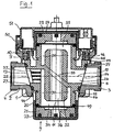
- the housing 1 comprises an inlet connection 2 and an outlet nozzle 3 on opposite sides of the housing are arranged in alignment. You can also - as is known - on the same side of the housing side by side or inside each other Arrange. These and other alternative designs of the housing should be covered by the inventive concept his.
- the sockets show connection threads 4 for connection with subsequent pipes. It understands themselves that the nozzle is also formed in a different way could be. For example, they can each be a final organ included, which serves the respective line branch shut off in order to mount or replace the measuring capsule to enable.
- the housing 1 forms a receptacle between the connecting pieces 2, 3 for the capsule 7.
- the capsule fits one receiving bore 8 with means for holding the capsule is formed in this hole.
- These facilities are in the example shown on the one hand by a retaining ring 9, the thread, bayonet or the like with a collar 10 of the intake cooperates, and the taper of the bore 8 formed.
- the axis 11 of the bore 8 intersects at right angles with the Axis 12 of the nozzle bores 13, 14. These therefore open at opposite positions of the bore 8.
- the capsule 7 consists of a middle piece 20, a lower one End piece 21 with a lower cover 22 and an upper end piece 23 with upper lid 24.
- the middle piece 20 contains openings 25, 26, which connect directly to the nozzle openings 13, 14, when the capsule is inserted in the receptacle and is suitable for the hole at least in the area of the openings 8 trained so that they are safe and in a certain position is held in the bore 8.
- the with regard to the Axial alignment of the openings desired orientation of the Capsule is formed by interlocking projections 28 and depressions 29 on the center piece or the capsule holder ensured.
- the interacting pairs of openings 13, 25 and 14, 26 are each surrounded by a sealing ring, which closes the opening connection completely tight.
- the capsule openings 25, 26 have an annular space 30, 31 in connection, which encloses the measuring tube 32, which by a Diagonal wall 33 is held within the capsule, the Diagonal wall on the one hand with the inlet opening 25 and on the other hand parts 30 connected to the outlet opening 26 or 31 of the annular space.
- These parts 30, 31 of the annulus form the so-called side channels.
- the side channels lead in the illustrated embodiment from the ends of the center piece to the center and are of equal length. It doesn't have to be that way.
- the side channels are of different lengths. One of they can be shortened to zero.
- the ends of the measuring tube 32 end at a distance from the front ends of the middle piece, so that there distribution chambers 34, 35 arise.
- the Flow path of the medium therefore leads from the bore 13 of the Inlet nozzle through the inlet opening 25 of the capsule in the Annulus part 30, through the lower distribution chamber 34 and Measuring section 36 to the distribution space 35 and through the annular space part 31 and the outlet-side opening 26 of the capsule in the Bore 14 of the outlet nozzle.
- the arrangement is symmetrical, since the axis 11 of the capsule and the recording the common axis 12 of the nozzle holes cuts at right angles. However, this is not absolutely necessary.
- axis 11 could be axis 12 be a little inclined or offset to the side.
- the nozzles 2, 3 are not arranged opposite one another the formation of the flow channels within the capsule nevertheless correspond to the illustrated embodiment, if the necessary flow diversions are provided in the housing are.
- the channel arrangement inside the capsule itself deviates from that To design representation, and preferably so that in the measuring section the most suitable for the measuring purposes Flow results. For example, to influence the Flow baffles are housed within the channels as at 37 in the inlet opening 25 of the capsule are indicated.
- the end pieces 21, 23 contain unspecified components for generating or recording a measurement signal and are through a membrane and sealing rings 49 opposite the front ends of the middle piece 20 sealed.
- Your lids 22, 24 are by snap connections indicated at 44 with the center piece connected so that the capsule is handled as a unit can be.
- the covers are secured in the installation position in that by means of a collar 45 behind one corresponding collar 46 of the receptacle or retaining ring 9 to grab. Not only the seat of the middle piece in the recording, but also the capsule caps are covered by the Retaining ring 9 secured. Only this one therefore needs to be sealed to become.
- the retaining ring 9 is a by means of a connecting ring 50 another lid 51 placed, if desired the Cable entry 52 to capsule 7 covers and also other cable guides may contain.
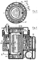
- Fig. 2 shows that to the housing 1, if desired, a counter 53 or the like can be applied.
- the further embodiment according to FIG. 4 has a housing 60 and a capsule 61 inserted therein. Not shown Inlet and outlet of the housing and the corresponding The openings of the capsule are interconnected as explained with reference to FIGS. 1 to 3 has been.
- the capsule 61 contains an impeller 62 as Measuring element, the movement of which by a transmitter / receiver pair 63, 64 is scanned, which is arranged on both sides of the impeller are. It is the passage of the wing through the measuring section 65 found.
- the cables 66 from the lower transmitter or receiver 64 are through those spaces between the capsule 61 and the receptacle formed in the housing 60 to the side of the other donor or recipient 63, which thanks to the Seals enclosing flow connections are free of medium are. Additional components can be found in the upper part 67 of the capsule for forwarding and / or displaying the measurement signal and for Cable entry can be provided.
- Claim 5 a possibly independent of the other claims Protection deserves.
Description
Die Ausbreitungsgeschwindigkeit von bestimmten Wellen, insbesondere Schallwellen, in einem fluiden Medium ist abhängig von dessen Relativgeschwindigkeit. Diese Erscheinung nutzt man in Ultraschallmeßgeräten zur Durchflußmessung. Das Gerät enthält eine von dem Medium durchströmte Meßstrecke, an deren einander gegenüberliegenden Enden entsprechende Geber bzw. Empfänger vorgesehen sind. Die Meßstrecke darf im Hinblick auf die zu erzielende Genauigkeit nicht sehr kurz sein. Erstreckt sie sich in Längsrichtung zwischen den Zu- und Ablaufstutzen des Meßgeräts (EP-A-392 294), gelangt man zu einer großen Baulänge, verlegt man die Meßstrecke außerhalb der die Stutzen verbindenden Flucht (EP-B-88 235). Das gilt auch dann, wenn die Meßstrecke zwar innerhalb dieser Flucht aber quer dazu angeordnet wird (EP-A-681 162). Dabei ist es bekannt (US-A-4 140 012), im Gehäuse neben dem quer angeordneten Meßrohr Seitenkanäle auszubilden, die einerseits mit je einem Stutzen und andererseits mit je einer Verteilkammer an den beiden Enden des Meßrohrs in Verbindung stehen. Das Gehäuse ist diagonal geteilt und enthält in der Teilungsebene eine Trennwand, die den zufuhrseitigen Seitenkanal und die zugehörige Verteilkammer von dem abfuhrseitigen trennt und von dem Meßrohr durchquert ist. Die Meßgeber und -empfänger sind in gesonderten Gehäuseöffnungen fluchtend mit dem Meßrohr angeordnet. Wenn zur Änderung des Meßbereichs das Meßrohr ausgewechselt werden muß, muß das Gehäuse insgesamt demontiert werden und zu diesem Zweck aus der zugehörigen Leitungsstrecke herausgenommen werden. Dies ist höchst umständlich. Die relative Lage der Geber, Empfänger sowie der Meßstrecke zueinander wird durch die Montagegenauigkeit des Gehäuses beeinflußt. Eine Eichung ist daher erst nach vollständiger Montage des Geräts möglich. Die Meßgenauigkeit kann durch Lageänderung der Geber und Empfänger gegenüber dem Gehäuse sowie der Lage der Gehäuseteile und des Meßrohres zueinander beeinträchtigt werden. Die Verbindung aller dieser Teile miteinander bedarf daher der Sicherung und Plombierung.The propagation speed of certain waves, in particular Sound waves in a fluid medium is dependent of its relative speed. This phenomenon uses one in ultrasonic measuring devices for flow measurement. The device contains a measuring section through which the medium flows; opposite ends of corresponding sensors or Recipients are provided. The measuring section may be considered be very short on the accuracy to be achieved. extends they are in the longitudinal direction between the inlet and outlet connections of the measuring device (EP-A-392 294), one arrives at one large overall length, you move the measuring section outside the the connecting flight (EP-B-88 235). This is also true then, when the measuring section is within this escape is arranged transversely thereto (EP-A-681 162). It is known (US-A-4 140 012), in the housing next to the transversely arranged Form measuring tube side channels, the one with each a nozzle and on the other hand each with a distribution chamber the two ends of the measuring tube. The housing is divided diagonally and contains in the division level a partition wall that the feed side channel and the separates the associated distribution chamber from the discharge side and is crossed by the measuring tube. The sensors and receivers are aligned with the measuring tube in separate housing openings arranged. If the measuring tube to change the measuring range must be replaced, the housing must be dismantled and for this purpose from the associated line section be taken out. This is extremely cumbersome. The relative position of the sensors, receivers and the measuring section to each other is due to the mounting accuracy of the housing affected. A calibration is therefore only complete Installation of the device possible. The measuring accuracy can by changing the position of the encoder and receiver relative to the housing and the position of the housing parts and the measuring tube to each other be affected. The connection of all of these Parts with each other therefore need to be secured and sealed.
Der Erfindung liegt die Aufgabe zugrunde, ein Durchflußmeßgerät in der im Oberbegriff des Anspruchs 1 (entsprechend US-A-4 140 012) genannten Art zu schaffen, das kurze und einfache Bauweise mit leichter Handhabbarkeit verbindet.The invention has for its object a flow meter in the preamble of claim 1 (corresponding to US-A-4 140 012) mentioned to create the short and simple Construction combined with easy handling.
Die erfindungsgemäße Lösung liegt in den Merkmalen des Anspruchs 1 und vorzugsweise denjenigen der Unteransprüche.The solution according to the invention lies in the features of the claim 1 and preferably that of the subclaims.
Danach bilden das Meßrohr, die Verteilkammern und die Seitenkanäle Teile einer von dem Gehäuse gesonderten und als Einheit montierbaren Kapsel. Zwar ist es von mechanischen Durchflußmeßgeräten bekannt (EP-B-682 234), den Meßsensor (beispielsweise ein Flügelrad) ggf. zusammen mit einem Zählwerk als selbständige Kapsel auszubilden, die als Einheit in das Gerätegehäuse eingesetzt werden kann. Jedoch konnte dieser Gedanke nicht ohne weiteres auf Ultraschallzähler übertragen werden, weil bei diesen die an entgegengesetzten Seiten befindlichen Geber bzw. Empfänger durch Gehäuseteile, nämlich Kanäle, Verteilkammern, und ggf. das Meßrohr, voneinander getrennt sind und daher nicht ohne weiteres zu einer Einheit zusammengeschlossen werden können. Dies wird erst durch den Erfindungsgedanken ermöglicht, sowohl die Kanäle, als auch die Verteilkammern und das Meßrohr in die Kapseleinheit einzubeziehen. Lediglich bei einem einfach aufgebauten Ultraschall-Durchflußmesser, bei dem die Meßkammer im wesentlichen nur eine Fortsetzung der Rohrleitung ist, in die der Durchflußmesser eingesetzt ist, ist die gesamte Meßeinheit als herausnehmbares Teil ausgebildet (EP-A-0 890 826). Da die Geber und Empfänger den Strom behindern würden, sind sie zusammen mit Reflektionseinrichtungen am Rand der Meßkammer angeordnet. Der Ultraschall wird dabei auf seinem Weg vom Geber zum Empfänger mehrfach reflektiert und verläuft schräg durch die Meßkammer. Heim erfindungsgemäßen Ultraschall-Durchflußmesser ist dagegen ein einfacher Meßweg, nämlich eine gerade Strecke möglich. The measuring tube, the distribution chambers and the side channels then form parts of a capsule separate from the housing and mountable as a unit. It is known from mechanical flowmeters (EP-B-682 234) to design the measuring sensor (for example an impeller) possibly together with a counter as an independent capsule which can be used as a unit in the device housing. However, this idea could not be easily transferred to ultrasonic meters, because the sensors or receivers located on opposite sides are separated from one another by housing parts, namely channels, distribution chambers, and possibly the measuring tube, and are therefore not easily combined to form a unit can be. This is only made possible by the idea of the invention to include both the channels and the distribution chambers and the measuring tube in the capsule unit. Only in the case of a simply constructed ultrasonic flow meter, in which the measuring chamber is essentially only a continuation of the pipeline into which the flow meter is inserted, is the entire measuring unit designed as a removable part (EP-A-0 890 826). Since the transmitters and receivers would hinder the current, they are arranged together with reflection devices on the edge of the measuring chamber. The ultrasound is reflected several times on its way from the transmitter to the receiver and runs diagonally through the measuring chamber. In contrast, at home the ultrasonic flow meter according to the invention, a simple measuring path, namely a straight line, is possible.
Die Erfindung erschöpft sich auch nicht darin, daß das Gehäuse kurz und einfach aufgebaut ist und ohne die empfindlichen Meßbestandteile installiert werden kann, die Handhabung einfach ist, weil bei Wartung oder Änderung des Meßbereichs einfach die Kapsel ausgetauscht werden kann, und es in vielen Fällen möglich sein wird, die Eichung ausschließlich an der Kapsel vorzusehen.The invention is not limited to the fact that the housing is short and simple and without the sensitive Measurement components can be installed, handling is simple is easy because when maintenance or changing the measuring range the capsule can be replaced and it in many Cases will be possible, the calibration only at the Provide capsule.
Die an den entgegengesetzten Enden der Kapsel vorgesehenen Geber bzw. Empfänger werden häufig jeweils kabelversorgt sein, beispielsweise zur Energieversorgung oder zur Signalabführung. Da die außerhalb des Geräts liegenden Kabel beschädigungseensibel sind, ist man bestrebt, die Zahl der Kabeleinführungen in das Gerät zu verringern und die freiliegen den Kabelstrecken zu reduzieren. Dieses Ziel erreicht die Erfindung dadurch, daß das Kapselmittelstück, welches die Kanäle bildet, außerhalb der mit der Kapselaufnahme zusammenwirkenden, gesondert und vollständig abgedichteten Öffnungen mediumfreie Räume mit der Kapselaufnahme einschließt, durch die die Kabel wenigstens eines kabelversorgten Endstücks der Kapsel zur anderen Seite der Kapsel hin geführt sind, wo sie gemeinsam mit den Kabeln des anderen Kapselendstücks aus dem Gerät herausgeführt werden können. Es können auch die Kabel beider Kapselendstücke durch diese Räume zu einer an dritter Stelle gelegenen Kabelabführungsstelle geführt werden. In jedem Falle dienen diese Räume oder innerhalb des Mittelstücks der Kapsel mit diesen Räumen verbundene Räume zur geschützten und trockenen Führung von Kabeln. The sensors or receivers provided on the opposite ends of the capsule will often be supplied with cables, for example for energy supply or for signal dissipation. Since the cables outside the device are sensitive to damage, efforts are being made to reduce the number of cable entries into the device and to reduce the exposed cable runs. The invention achieves this aim in that the capsule center piece, which forms the channels, includes medium-free spaces with the capsule receptacle outside the cooperating with the capsule receptacle, separately and completely sealed openings, through which the cables at least one cable-supplied end piece of the capsule to the other side of the capsule are led where they can be led out of the device together with the cables of the other capsule end piece. The cables of both capsule end pieces can also be routed through these rooms to a cable outlet point located at a third position. In any case, these spaces or spaces connected to these spaces within the center piece of the capsule serve for the protected and dry routing of cables.
Vorteilhafterweise ist die Kapselaufnahme beiderseits offen, so daß sie zwei einander entgegengesetzt liegende Öffnungen aufweist. Mindestens aus einer dieser Öffnungen wird die Kapsel im allgemeinen herausragen. Bei symmetrischer Anordnung, die im allgemeinen Vorteile hat, kann sie mit beiden ihrer Enden aus den Öffnungen herausragen.The capsule holder is advantageously open on both sides, so that they have two opposing openings having. At least one of these openings becomes the capsule generally stand out. With a symmetrical arrangement, which generally has advantages, it can be used with either of them Stick ends out of the openings.
Im allgemeinen wird es erforderlich sein, die Geber/Empfänger oder deren Aufnahmeräume an den Enden der Kapsel durch Deckel zu sichern. Diese können zwar in beliebiger Weise mit dem übrigen Teil der Kapsel verbunden sein, um mit dieser als Einheit gehandhabt werden zu können. Falls sie von Innendruck beaufschlagt sind, werden sie aber zweckmäßigerweise zusätzlich mit dem Gehäuse verbunden, um die aus dem Innendruck resultierenden Kräfte direkt auf dieses übertragen zu können. Ferner werden sie nach einem besonderen Merkmal der Erfindung durch diejenigen Mittel an der Kapsel gesichert, die auch die Kapsel in der Aufnahme des Gehäuses sichern. Dadurch wird nicht nur die Konstruktion vereinfacht, sondern auch ermöglicht, mit lediglich einer Sicherung und Plombierung für die gesamte Kapsel auszukommen.Generally it will be necessary to be the donor / recipient or their receiving spaces at the ends of the capsule through lids to secure. This can be done in any way with the rest Part of the capsule to be connected to this as a unit to be able to be handled. In case of internal pressure are applied, but they are expediently additional connected to the housing to the resulting from the internal pressure To be able to transfer forces directly to it. Furthermore, they are according to a special feature of the invention secured to the capsule by those means which also the Secure the capsule in the holder of the housing. This will not only simplifies the design, but also enables with only one securing and sealing for the entire capsule get along.
Die Erfindung wird im folgenden näher unter Bezugnahme auf die Zeichnung erläutert, die ein vorteilhaftes Ausführungsbeispiel veranschaulicht. Es zeigen:
- Fig. 1
- einen Schnitt längs durch das Gehäuse und die Kapsel;
- Fig. 2
- einen Schnitt quer zum Gehäuse und längs zur Kapsel;
- Fig. 3
- eine Schnittansicht der Kapsel gemäß Linie III-III der Fig. 2; und
- Fig. 4
- einen Schnitt durch eine weitere Ausführungsform.
- Fig. 1
- a section longitudinally through the housing and the capsule;
- Fig. 2
- a section transverse to the housing and longitudinal to the capsule;
- Fig. 3
- a sectional view of the capsule according to line III-III of Fig. 2; and
- Fig. 4
- a section through a further embodiment.
Es wird zunächst auf die Ausführungsform gemäß Fig. 1 bis 3
bezug genommen. Das Gehäuse 1 umfaßt einen Zulaufstutzen 2
und einen Auslaufstutzen 3, die an gegenüberliegenden Seiten
des Gehäuses fluchtend angeordnet sind. Man kann sie auch -
wie bekannt - an derselben Seite des Gehäuses neben- oder ineinanderliegend
anordnen. Solche und andere Ausführungsalternativen
des Gehäuses sollen vom Erfindungsgedanken umfaßt
sein. Die Stutzen zeigen im dargestellten Beispiel Anschlußgewinde
4 zur Verbindung mit anschließenden Rohren. Es versteht
sich, daß die Stutzen auch in anderer Weise ausgebildet
sein können. Beispielsweise können sie jeweils ein Abschlußorgan
enthalten, das dazu dient, den jeweiligen Leitungszweig
abzusperren, um eine Montage oder Auswechslung der Meßkapsel
zu ermöglichen.It will first refer to the embodiment according to FIGS. 1 to 3
referred. The housing 1 comprises an inlet connection 2
and an outlet nozzle 3 on opposite sides
of the housing are arranged in alignment. You can also -
as is known - on the same side of the housing side by side or inside each other
Arrange. These and other alternative designs
of the housing should be covered by the inventive concept
his. In the example shown, the sockets show
Zwischen den Stutzen 2, 3 bildet das Gehäuse 1 eine Aufnahme
für die Kapsel 7. Die Aufnahme wird von einer die Kapsel passend
aufnehmenden Bohrung 8 mit Einrichtungen zum Festhalten
der Kapsel in dieser Bohrung gebildet. Diese Einrichtungen
werden im gezeigten Beispiel einerseits von einem Haltering
9, der über Gewinde, Bajonett oder dergleichen mit einem Kragen
10 der Aufnahme zusammenwirkt, und der Konizität der Bohrung
8 gebildet.The housing 1 forms a receptacle between the connecting pieces 2, 3
for the
Die Achse 11 der Bohrung 8 kreuzt sich rechtwinklig mit der
Achse 12 der Stutzenbohrungen 13, 14. Diese öffnen sich daher
an gegenüberliegenden Stellen der Bohrung 8.The axis 11 of the bore 8 intersects at right angles with the
Die Kapsel 7 besteht aus einem Mittelstück 20, einem unteren
Endstück 21 mit unterem Deckel 22 sowie einem oberen Endstück
23 mit oberem Deckel 24. Das Mittelstück 20 enthält Öffnungen
25, 26, die unmittelbar an die Stutzenöffnungen 13, 14 anschließen,
wenn die Kapsel in die Aufnahme eingesetzt ist und
ist zumindest im Bereich der Öffnungen passend zu der Bohrung
8 ausgebildet, so daß sie sicher und in bestimmter Position
in der Bohrung 8 gehalten ist. Die im Hinblick auf die
Achsübereinstimmung der Öffnungen erwünschte Ausrichtung der
Kapsel wird durch formschlüssig zusammenwirkende Vorsprünge
28 und Vertiefungen 29 an dem Mittelstück bzw. der Kapselaufnahme
sichergestellt. Die zusammenwirkenden Öffnungspaare 13,
25 bzw. 14, 26 werden jeweils von einem Dichtungsring umschlossen,
der die Öffnungsverbindung vollständig dicht abschließt.The
Die Kapselöffnungen 25, 26 stehen mit einem Ringraum 30, 31
in Verbindung, der das Meßrohr 32 umschließt, das durch eine
Diagonalwand 33 innerhalb der Kapsel gehalten ist, wobei die
Diagonalwand die einerseits mit der Zulauföffnung 25 und andererseits
mit der Auslauföffnung 26 verbundenen Teile 30
bzw. 31 des Ringraums voneinander trennt. Diese Teile 30, 31
des Ringraums bilden die sogenannten Seitenkanäle. Sie verlaufen
im Ausführungsbeispiel gegenparallel zur Meßstrecke,
d.h. werden gegensinnig zu dieser durchströmt. Je nach Ausführung
können sie von der parallelen Ausrichtung abweichen;
diese ist aber vorteilhaft zur Erzielung einer kurzen Baulänge.
Die Seitenkanäle führen im dargestellten Ausführungsbeispiel
von den Enden des Mittelstücks zu dessen Mitte und sind
gleich lang. Das muß nicht so sein. Wenn die Öffnungen 25, 26
einem der Enden des Mittelkörpers näher liegen als dem anderen,
sind die Seitenkanäle unterschiedlich lang. Einer von
ihnen kann bis auf Null verkürzt sein. Die Enden des Meßrohrs
32 enden in Abstand von den stirnseitigen Enden des Mittelstücks,
so daß dort Verteilkammern 34, 35 entstehen. Der
Strömungsweg des Mediums führt daher von der Bohrung 13 des
Zulaufstutzens durch die Zulauföffnung 25 der Kapsel in den
Ringraumteil 30, durch die untere Verteilkammer 34 und die
Meßstrecke 36 zu dem Verteilraum 35 und durch den Ringraumteil
31 und die auslaufseitige Öffnung 26 der Kapsel in die
Bohrung 14 des Auslaufstutzens.The
Die Anordnung ist symmetrisch, da die Achse 11 der Kapsel und
der Aufnahme die gemeinsame Achse 12 der Stutzenbohrungen
rechtwinklig schneidet. Dies ist aber nicht unbedingt erforderlich.
Beispielsweise könnte die Achse 11 zu der Achse 12
ein wenig geneigt oder seitlich zu ihr versetzt sein. Wenn
die Stutzen 2, 3 nicht gegenüberliegend angeordnet sind, kann
die Ausbildung der Strömungskanäle innerhalb der Kapsel
gleichwohl dem dargestellten Ausführungsbeispiel entsprechen,
wenn die erforderlichen Strömungsumführungen im Gehäuse vorgesehen
sind. Jedoch besteht auch die Möglichkeit, die Kanalanordnung
innerhalb der Kapsel selbst abweichend von der
Darstellung zu gestalten, und zwar vorzugsweise so, daß sich
in der Meßstrecke die für die Meßzwecke am besten geeignete
Strömung ergibt. Beispielsweise können zur Beeinflussung der
Strömung Leitflächen innerhalb der Kanäle untergebracht werden,
wie sie bei 37 in der zulaufseitigen Öffnung 25 der Kapsel
angedeutet sind.The arrangement is symmetrical, since the axis 11 of the capsule and
the recording the
Die Endstücke 21, 23 enthalten nicht näher bezeichnete Komponenten
zur Erzeugung bzw. Aufnahme eines Meßsignals und sind
durch eine Membran und Dichtringe 49 gegenüber den Stirnenden
des Mittelstücks 20 abgedichtet. Ihre Deckel 22, 24 sind
durch bei 44 angedeutete Schnappverbindungen mit dem Mittelstück
verbunden, so daß die Kapsel als Einheit gehandhabt
werden kann. In der Einbaustellung gesichert werden die Dekkel
dadurch, daß sie mittels eines Kragens 45 hinter einen
entsprechenden Bund 46 der Aufnahme oder des Halterings 9
greifen. Nicht nur der Sitz des Mittelstücks in der Aufnahme,
sondern auch die Deckel der Kapsel werden somit durch den
Haltering 9 gesichert. Nur dieser braucht daher auch plombiert
zu werden.The
Dem Haltering 9 ist mittels eines Verbindungsrings 50 ein
weiterer Deckel 51 aufgesetzt, der gewünschtenfalls die
Kabeleinführung 52 zur Kapsel 7 abdeckt und auch weitere Kabelführungen
enthalten kann.The retaining
In Fig. 2 und 3 erkennt man die Kabelführung von dem unteren
Endstück 21 zum oberen Endstück 23 der Kapsel. Die Wand 48
des Meßrohrs, die die Seitenkanäle 30, 31 außen begrenzt, ist
- wie in Fig. 3 rechts erkennbar - auf einer Seite ein wenig
exzentrisch nach innen hin zurückgenommen. Das gilt auch für
den Verlauf der Dichtungen 49 zwischen den stirnseitigen Enden
dieser Wand und den Endstücken 21, 23 der Kapsel. Dadurch
wird Platz geschaffen für eine Bohrung 52, die die Endstücke
durch das Mittelstück hindurch verbindet. Diese Lösung wird
dadurch möglich, daß diese Bohrung bzw. die Räume, mit denen
sie kommuniziert, durch die Dichtungen 49 zwischen dem Kapselmittelstück
und den Endstücken einerseits und die Dichtungen
27 an den Kapselöffnungen 25, 26 andererseits von sämtlichen
mediumführenden Räumen getrennt ist. So läßt sich die
Kapsel mit einseitiger Kabelzuführung ausbilden.2 and 3 you can see the cable routing from the
Hervorzuheben ist, daß im Mittelstück 20 die Wände 48, alle
mit der Aufnahme bzw. dem Gehäuse 1 zusammenwirkenden Teile,
die Diagonalwand 33 und das Meßrohr 32 (oder Teile, die ein
auswechselbares Meßrohr halten) einstückig zusammengefaßt
sind, was im Hinblick auf die Fertigungskosten einen erheblichen
Vorteil darstellt.It should be emphasized that in the
Fig. 2 zeigt, daß an das Gehäuse 1 gewünschtenfalls ein Zählwerk
53 oder dergleichen angesetzt werden kann.Fig. 2 shows that to the housing 1, if desired, a
Die weitere Ausführungsform gemäß Fig. 4 besitzt ein Gehäuse
60 und eine darin eingesetzte Kapsel 61. Die nicht dargestellten
Zulauf- und Auslaufstutzen des Gehäuses und die entsprechenden
Öffnungen der Kapsel sind so miteinander verbunden,
wie dies unter Bezugnahme auf Fig. 1 bis 3 erläutert
wurde.The further embodiment according to FIG. 4 has a
Abweichend davon enthält die Kapsel 61 ein Flügelrad 62 als
Meßorgan, dessen Bewegung durch ein Geber/Empfänger-Paar 63,
64 abgetastet wird, die beiderseits des Flügelrads angeordnet
sind. Es wird der Durchgang der Flügel durch die Meßstrecke
65 festgestellt. Die Kabel 66 von dem unteren Geber bzw. Empfänger
64 werden durch diejenigen Räume zwischen der Kapsel
61 und der im Gehäuse 60 gebildeten Aufnahme zu der Seite des
anderen Gebers bzw. Empfängers 63 geführt, die dank den die
Strömungsverbindungen umschließenden Dichtungen mediumsfrei
sind. Im Oberteil 67 der Kapsel können weitere Komponenten
zur Weiterleitung und/oder Anzeige des Meßsignals sowie zur
Kabeldurchführung vorgesehen sein. Das Beispiel zeigt, daß
Anspruch 5 einen ggf. von den übrigen Ansprüchen unabhängigen
Schutz verdient.In a departure from this, the
Claims (5)
- Flowmeter for fluid media, comprising a housing having an inlet connection (2) and an outlet connection (3) and which contains a measuring section (36) with a measuring tube (32) which connects two distribution chambers (34, 35) which are each connected to one of the two connections (2, 3) by side channels (30, 31) placed substantially beside the measuring tube (32), characterized in that the measuring tube (32), the distribution chambers (34, 35) and the side channels (30, 31) are part of a capsule (7) which is separate from the housing (1) and can be inserted as a unit into a capsule holder provided in the housing (1), in that the side channels (30, 31) are connected to the connections (2, 3) via pairs of openings (13, 25 and 26, 14) arranged on the capsule (7) and in the capsule holder, in that the cables (66) are led away to one side of the capsule (7), and in that the capsule (7, 61), at its end lying away from the cable output side of the instrument or the capsule has a cable-supplied transmitter/receiver (21, 64) and the capsule encloses medium-free spaces of the capsule holder outside the pairs of openings (13, 25 and 26, 12) interacting closely with the capsule holder, and the cables of the cable-supplied transmitter/receiver (21, 64) run to the cable output side through these spaces or spaces connected thereto within the capsule.
- Flowmeter according to Claim 1, characterized in that the capsule holder is open on both sides, and the capsule (7) projects therefrom with at least one of its ends.
- Flowmeter according to Claim 1 or 2, characterized in that the capsule has at least one cover (22, 24), which is secured against internal overpressure by interacting with holding means (45, 46) provided on the housing (1).
- Flowmeter according to Claim 3, characterized in that the cover (22, 24) is secured on the capsule (7) by the same means (9, 10) which can be lead-sealed and which secure the capsule (7) in the holder.
- Flowmeter according to one of Claims 1 to 3, characterized in that the measuring section is arranged transversely with respect to the inlet and/or outlet connection (2, 3).
Priority Applications (2)
| Application Number | Priority Date | Filing Date | Title |
|---|---|---|---|
| DE59904940T DE59904940D1 (en) | 1999-01-15 | 1999-01-15 | Flow meter for fluid media |
| EP19990100712 EP1020711B1 (en) | 1999-01-15 | 1999-01-15 | Flowmeter for fluids |
Applications Claiming Priority (1)
| Application Number | Priority Date | Filing Date | Title |
|---|---|---|---|
| EP19990100712 EP1020711B1 (en) | 1999-01-15 | 1999-01-15 | Flowmeter for fluids |
Publications (2)
| Publication Number | Publication Date |
|---|---|
| EP1020711A1 EP1020711A1 (en) | 2000-07-19 |
| EP1020711B1 true EP1020711B1 (en) | 2003-04-09 |
Family
ID=8237355
Family Applications (1)
| Application Number | Title | Priority Date | Filing Date |
|---|---|---|---|
| EP19990100712 Expired - Lifetime EP1020711B1 (en) | 1999-01-15 | 1999-01-15 | Flowmeter for fluids |
Country Status (2)
| Country | Link |
|---|---|
| EP (1) | EP1020711B1 (en) |
| DE (1) | DE59904940D1 (en) |
Cited By (1)
| Publication number | Priority date | Publication date | Assignee | Title |
|---|---|---|---|---|
| CN102162745A (en) * | 2010-02-16 | 2011-08-24 | 伊特伦法国公司 | Standardised capsule-type meter with an ultrasound measurement cell |
Families Citing this family (8)
| Publication number | Priority date | Publication date | Assignee | Title |
|---|---|---|---|---|
| DE10103745C2 (en) | 2001-01-26 | 2003-04-17 | Hydrometer Gmbh | Ultrasonic counter with an interchangeable measuring section with central sensor attachment |
| DE10119342C2 (en) * | 2001-04-20 | 2003-07-31 | Hydrometer Gmbh | liquid meter |
| DE102005001897C5 (en) * | 2005-01-14 | 2013-01-17 | Landis+Gyr Gmbh | Ultrasonic measuring arrangement for installation on a Einrohranschlussstück in a pipeline |
| DE102005062629B4 (en) * | 2005-12-23 | 2008-01-24 | Hydrometer Gmbh | Flowmeter |
| EP1909076B1 (en) * | 2006-10-04 | 2011-05-18 | Hans-Holger Körner | Flowmeter for fluid media |
| DE202008002816U1 (en) * | 2008-02-29 | 2009-04-16 | Junker, Raul | Device for flow measurement |
| DE202009004358U1 (en) | 2008-03-28 | 2009-08-20 | Körner, Hans-Holger | Flowmeter with eccentric measuring tube |
| DE202009016421U1 (en) * | 2009-12-04 | 2011-04-14 | Körner, Hans-Holger | Measuring capsule for flow measurement |
Family Cites Families (5)
| Publication number | Priority date | Publication date | Assignee | Title |
|---|---|---|---|---|
| US4140012A (en) * | 1977-11-07 | 1979-02-20 | Envirotech Corporation | Small pipe flowmeter |
| DE3518266A1 (en) * | 1985-05-21 | 1986-11-27 | Siemens AG, 1000 Berlin und 8000 München | FLOWMETER |
| US5463906A (en) * | 1994-01-24 | 1995-11-07 | Triton Technology, Inc. | Interchangeable disposable acoustic for use with an ultrasonic flowmeter, particularly during extracorporeal measurement of blood flow |
| EP0682234B1 (en) * | 1994-05-09 | 1997-08-27 | Hans-Holger Körner | Fluorometer for liquids and gasses |
| DE19729473A1 (en) * | 1997-07-10 | 1999-02-04 | Meinecke Ag H | Ultrasonic flow meter |
-
1999
- 1999-01-15 DE DE59904940T patent/DE59904940D1/en not_active Expired - Lifetime
- 1999-01-15 EP EP19990100712 patent/EP1020711B1/en not_active Expired - Lifetime
Cited By (1)
| Publication number | Priority date | Publication date | Assignee | Title |
|---|---|---|---|---|
| CN102162745A (en) * | 2010-02-16 | 2011-08-24 | 伊特伦法国公司 | Standardised capsule-type meter with an ultrasound measurement cell |
Also Published As
| Publication number | Publication date |
|---|---|
| DE59904940D1 (en) | 2003-05-15 |
| EP1020711A1 (en) | 2000-07-19 |
Similar Documents
| Publication | Publication Date | Title |
|---|---|---|
| EP1020711B1 (en) | Flowmeter for fluids | |
| DE2646358C2 (en) | Hollow fiber dialyzer | |
| DE102008049891B4 (en) | Flow straightener for a flowmeter, in particular an ultrasonic measuring device | |
| EP3314214B1 (en) | Flowmeter with measuring flow channel and auxiliary flow channels | |
| DE2458901C3 (en) | Flow meter | |
| EP3485233A1 (en) | Flow meter with measuring channel | |
| EP0890826A1 (en) | Ultrasonic flowmeter | |
| DE10204715B4 (en) | Ultrasonic flow meter | |
| EP2283262B1 (en) | Multi-way valve of a fuel system of a gas turbine | |
| DE10103745C2 (en) | Ultrasonic counter with an interchangeable measuring section with central sensor attachment | |
| EP1909076B1 (en) | Flowmeter for fluid media | |
| DE19717725A1 (en) | Compound water meter | |
| EP0559938A1 (en) | Ultrasonic through put measuring device for liquids | |
| DE3743972A1 (en) | FLOWMETER | |
| DE7631936U1 (en) | GRAET FOR MEASURING AIR SPEED | |
| DE102014216553B3 (en) | Flow meter with a measuring insert inserted into a housing | |
| EP2239544B1 (en) | Measuring capsule for fluid counter and fluid counter | |
| DE102005062629B4 (en) | Flowmeter | |
| EP2604982B1 (en) | Device for contact-free throughflow measurement of fluids in flexible hoses | |
| DE19843124C2 (en) | Suction pulsator | |
| DE1623801B2 (en) | MAGNETIC DRIVE COUPLING FOR MEASURING DEVICES, SUCH AS FLOW METERS AND THE like. | |
| DE3104134A1 (en) | Flow meter | |
| DE10233307B4 (en) | The mass flow meter | |
| DE19731173A1 (en) | Ultrasound flow quantity measurement arrangement | |
| DE102008032309A1 (en) | Sensor arrangement for measuring condition of liquid, particularly oil in motor vehicle engine of motor vehicle, has sensor and contact area in component |
Legal Events
| Date | Code | Title | Description |
|---|---|---|---|
| PUAI | Public reference made under article 153(3) epc to a published international application that has entered the european phase |
Free format text: ORIGINAL CODE: 0009012 |
|
| AK | Designated contracting states |
Kind code of ref document: A1 Designated state(s): DE DK FR GB IT |
|
| AX | Request for extension of the european patent |
Free format text: AL;LT;LV;MK;RO;SI |
|
| 17P | Request for examination filed |
Effective date: 20010117 |
|
| AKX | Designation fees paid |
Free format text: DE DK FR GB IT |
|
| GRAH | Despatch of communication of intention to grant a patent |
Free format text: ORIGINAL CODE: EPIDOS IGRA |
|
| GRAH | Despatch of communication of intention to grant a patent |
Free format text: ORIGINAL CODE: EPIDOS IGRA |
|
| GRAA | (expected) grant |
Free format text: ORIGINAL CODE: 0009210 |
|
| AK | Designated contracting states |
Designated state(s): DE DK FR GB IT |
|
| PG25 | Lapsed in a contracting state [announced via postgrant information from national office to epo] |
Ref country code: IT Free format text: LAPSE BECAUSE OF FAILURE TO SUBMIT A TRANSLATION OF THE DESCRIPTION OR TO PAY THE FEE WITHIN THE PRESCRIBED TIME-LIMIT;WARNING: LAPSES OF ITALIAN PATENTS WITH EFFECTIVE DATE BEFORE 2007 MAY HAVE OCCURRED AT ANY TIME BEFORE 2007. THE CORRECT EFFECTIVE DATE MAY BE DIFFERENT FROM THE ONE RECORDED. Effective date: 20030409 Ref country code: GB Free format text: LAPSE BECAUSE OF FAILURE TO SUBMIT A TRANSLATION OF THE DESCRIPTION OR TO PAY THE FEE WITHIN THE PRESCRIBED TIME-LIMIT Effective date: 20030409 Ref country code: FR Free format text: LAPSE BECAUSE OF FAILURE TO SUBMIT A TRANSLATION OF THE DESCRIPTION OR TO PAY THE FEE WITHIN THE PRESCRIBED TIME-LIMIT Effective date: 20030409 |
|
| REG | Reference to a national code |
Ref country code: GB Ref legal event code: FG4D Free format text: NOT ENGLISH |
|
| PG25 | Lapsed in a contracting state [announced via postgrant information from national office to epo] |
Ref country code: DK Free format text: LAPSE BECAUSE OF FAILURE TO SUBMIT A TRANSLATION OF THE DESCRIPTION OR TO PAY THE FEE WITHIN THE PRESCRIBED TIME-LIMIT Effective date: 20030709 |
|
| GBV | Gb: ep patent (uk) treated as always having been void in accordance with gb section 77(7)/1977 [no translation filed] |
Effective date: 20030409 |
|
| PLBE | No opposition filed within time limit |
Free format text: ORIGINAL CODE: 0009261 |
|
| STAA | Information on the status of an ep patent application or granted ep patent |
Free format text: STATUS: NO OPPOSITION FILED WITHIN TIME LIMIT |
|
| EN | Fr: translation not filed | ||
| 26N | No opposition filed |
Effective date: 20040112 |
|
| PGFP | Annual fee paid to national office [announced via postgrant information from national office to epo] |
Ref country code: DE Payment date: 20120321 Year of fee payment: 14 |
|
| PG25 | Lapsed in a contracting state [announced via postgrant information from national office to epo] |
Ref country code: DE Free format text: LAPSE BECAUSE OF NON-PAYMENT OF DUE FEES Effective date: 20130801 |
|
| REG | Reference to a national code |
Ref country code: DE Ref legal event code: R119 Ref document number: 59904940 Country of ref document: DE Effective date: 20130801 |