EP3637014B1 - Kombiheizgerärt zum erhitzen von brauchwasser und heizwasser eines raums mit drei-wege-wärmetauscher - Google Patents
Kombiheizgerärt zum erhitzen von brauchwasser und heizwasser eines raums mit drei-wege-wärmetauscher Download PDFInfo
- Publication number
- EP3637014B1 EP3637014B1 EP19201102.1A EP19201102A EP3637014B1 EP 3637014 B1 EP3637014 B1 EP 3637014B1 EP 19201102 A EP19201102 A EP 19201102A EP 3637014 B1 EP3637014 B1 EP 3637014B1
- Authority
- EP
- European Patent Office
- Prior art keywords
- heating
- water
- combined device
- storage tank
- heat exchanger
- Prior art date
- Legal status (The legal status is an assumption and is not a legal conclusion. Google has not performed a legal analysis and makes no representation as to the accuracy of the status listed.)
- Active
Links
- XLYOFNOQVPJJNP-UHFFFAOYSA-N water Substances O XLYOFNOQVPJJNP-UHFFFAOYSA-N 0.000 title claims description 230
- 238000010438 heat treatment Methods 0.000 title claims description 97
- 239000012530 fluid Substances 0.000 title claims description 30
- 239000008236 heating water Substances 0.000 claims description 112
- 238000003860 storage Methods 0.000 claims description 112
- 238000009434 installation Methods 0.000 claims description 56
- 239000013529 heat transfer fluid Substances 0.000 claims description 33
- 238000004891 communication Methods 0.000 claims description 17
- 230000001105 regulatory effect Effects 0.000 claims description 3
- 230000008878 coupling Effects 0.000 claims 15
- 238000010168 coupling process Methods 0.000 claims 15
- 238000005859 coupling reaction Methods 0.000 claims 15
- 238000009826 distribution Methods 0.000 description 11
- RYGMFSIKBFXOCR-UHFFFAOYSA-N Copper Chemical compound [Cu] RYGMFSIKBFXOCR-UHFFFAOYSA-N 0.000 description 4
- 238000009833 condensation Methods 0.000 description 4
- 230000005494 condensation Effects 0.000 description 4
- 229910052802 copper Inorganic materials 0.000 description 4
- 239000010949 copper Substances 0.000 description 4
- 238000000034 method Methods 0.000 description 4
- 238000005276 aerator Methods 0.000 description 3
- 241001631457 Cannula Species 0.000 description 2
- 230000008901 benefit Effects 0.000 description 2
- 238000011109 contamination Methods 0.000 description 2
- 230000008021 deposition Effects 0.000 description 2
- 238000001514 detection method Methods 0.000 description 2
- 238000010586 diagram Methods 0.000 description 2
- 238000004519 manufacturing process Methods 0.000 description 2
- 239000000463 material Substances 0.000 description 2
- BASFCYQUMIYNBI-UHFFFAOYSA-N platinum Chemical compound [Pt] BASFCYQUMIYNBI-UHFFFAOYSA-N 0.000 description 2
- 230000009467 reduction Effects 0.000 description 2
- 238000010257 thawing Methods 0.000 description 2
- 229910000881 Cu alloy Inorganic materials 0.000 description 1
- 230000009471 action Effects 0.000 description 1
- 238000000429 assembly Methods 0.000 description 1
- 230000005540 biological transmission Effects 0.000 description 1
- 230000015572 biosynthetic process Effects 0.000 description 1
- 230000015556 catabolic process Effects 0.000 description 1
- 238000010276 construction Methods 0.000 description 1
- 239000002826 coolant Substances 0.000 description 1
- 238000005520 cutting process Methods 0.000 description 1
- 238000006731 degradation reaction Methods 0.000 description 1
- 230000000593 degrading effect Effects 0.000 description 1
- 238000010494 dissociation reaction Methods 0.000 description 1
- 230000005593 dissociations Effects 0.000 description 1
- 230000009977 dual effect Effects 0.000 description 1
- 230000000694 effects Effects 0.000 description 1
- 238000005265 energy consumption Methods 0.000 description 1
- 235000021183 entrée Nutrition 0.000 description 1
- 230000010354 integration Effects 0.000 description 1
- 230000007257 malfunction Effects 0.000 description 1
- 238000005457 optimization Methods 0.000 description 1
- 210000000056 organ Anatomy 0.000 description 1
- 230000002093 peripheral effect Effects 0.000 description 1
- 238000009428 plumbing Methods 0.000 description 1
- 230000008569 process Effects 0.000 description 1
- 238000011084 recovery Methods 0.000 description 1
- 239000000725 suspension Substances 0.000 description 1
- 238000004804 winding Methods 0.000 description 1
Images


Classifications
-
- F—MECHANICAL ENGINEERING; LIGHTING; HEATING; WEAPONS; BLASTING
- F24—HEATING; RANGES; VENTILATING
- F24D—DOMESTIC- OR SPACE-HEATING SYSTEMS, e.g. CENTRAL HEATING SYSTEMS; DOMESTIC HOT-WATER SUPPLY SYSTEMS; ELEMENTS OR COMPONENTS THEREFOR
- F24D3/00—Hot-water central heating systems
- F24D3/08—Hot-water central heating systems in combination with systems for domestic hot-water supply
-
- F—MECHANICAL ENGINEERING; LIGHTING; HEATING; WEAPONS; BLASTING
- F24—HEATING; RANGES; VENTILATING
- F24D—DOMESTIC- OR SPACE-HEATING SYSTEMS, e.g. CENTRAL HEATING SYSTEMS; DOMESTIC HOT-WATER SUPPLY SYSTEMS; ELEMENTS OR COMPONENTS THEREFOR
- F24D17/00—Domestic hot-water supply systems
- F24D17/0026—Domestic hot-water supply systems with conventional heating means
- F24D17/0031—Domestic hot-water supply systems with conventional heating means with accumulation of the heated water
-
- F—MECHANICAL ENGINEERING; LIGHTING; HEATING; WEAPONS; BLASTING
- F24—HEATING; RANGES; VENTILATING
- F24D—DOMESTIC- OR SPACE-HEATING SYSTEMS, e.g. CENTRAL HEATING SYSTEMS; DOMESTIC HOT-WATER SUPPLY SYSTEMS; ELEMENTS OR COMPONENTS THEREFOR
- F24D17/00—Domestic hot-water supply systems
- F24D17/02—Domestic hot-water supply systems using heat pumps
-
- F—MECHANICAL ENGINEERING; LIGHTING; HEATING; WEAPONS; BLASTING
- F24—HEATING; RANGES; VENTILATING
- F24D—DOMESTIC- OR SPACE-HEATING SYSTEMS, e.g. CENTRAL HEATING SYSTEMS; DOMESTIC HOT-WATER SUPPLY SYSTEMS; ELEMENTS OR COMPONENTS THEREFOR
- F24D19/00—Details
- F24D19/10—Arrangement or mounting of control or safety devices
- F24D19/1006—Arrangement or mounting of control or safety devices for water heating systems
- F24D19/1066—Arrangement or mounting of control or safety devices for water heating systems for the combination of central heating and domestic hot water
- F24D19/1072—Arrangement or mounting of control or safety devices for water heating systems for the combination of central heating and domestic hot water the system uses a heat pump
-
- F—MECHANICAL ENGINEERING; LIGHTING; HEATING; WEAPONS; BLASTING
- F24—HEATING; RANGES; VENTILATING
- F24D—DOMESTIC- OR SPACE-HEATING SYSTEMS, e.g. CENTRAL HEATING SYSTEMS; DOMESTIC HOT-WATER SUPPLY SYSTEMS; ELEMENTS OR COMPONENTS THEREFOR
- F24D3/00—Hot-water central heating systems
- F24D3/18—Hot-water central heating systems using heat pumps
-
- F—MECHANICAL ENGINEERING; LIGHTING; HEATING; WEAPONS; BLASTING
- F24—HEATING; RANGES; VENTILATING
- F24H—FLUID HEATERS, e.g. WATER OR AIR HEATERS, HAVING HEAT-GENERATING MEANS, e.g. HEAT PUMPS, IN GENERAL
- F24H1/00—Water heaters, e.g. boilers, continuous-flow heaters or water-storage heaters
- F24H1/48—Water heaters for central heating incorporating heaters for domestic water
- F24H1/52—Water heaters for central heating incorporating heaters for domestic water incorporating heat exchangers for domestic water
- F24H1/526—Pipes in pipe heat exchangers for sanitary water
-
- F—MECHANICAL ENGINEERING; LIGHTING; HEATING; WEAPONS; BLASTING
- F24—HEATING; RANGES; VENTILATING
- F24H—FLUID HEATERS, e.g. WATER OR AIR HEATERS, HAVING HEAT-GENERATING MEANS, e.g. HEAT PUMPS, IN GENERAL
- F24H4/00—Fluid heaters characterised by the use of heat pumps
- F24H4/02—Water heaters
- F24H4/04—Storage heaters
-
- F—MECHANICAL ENGINEERING; LIGHTING; HEATING; WEAPONS; BLASTING
- F24—HEATING; RANGES; VENTILATING
- F24H—FLUID HEATERS, e.g. WATER OR AIR HEATERS, HAVING HEAT-GENERATING MEANS, e.g. HEAT PUMPS, IN GENERAL
- F24H9/00—Details
- F24H9/06—Arrangement of mountings or supports for heaters, e.g. boilers, other than space heating radiators
-
- F—MECHANICAL ENGINEERING; LIGHTING; HEATING; WEAPONS; BLASTING
- F24—HEATING; RANGES; VENTILATING
- F24H—FLUID HEATERS, e.g. WATER OR AIR HEATERS, HAVING HEAT-GENERATING MEANS, e.g. HEAT PUMPS, IN GENERAL
- F24H9/00—Details
- F24H9/12—Arrangements for connecting heaters to circulation pipes
- F24H9/13—Arrangements for connecting heaters to circulation pipes for water heaters
- F24H9/133—Storage heaters
-
- F—MECHANICAL ENGINEERING; LIGHTING; HEATING; WEAPONS; BLASTING
- F28—HEAT EXCHANGE IN GENERAL
- F28D—HEAT-EXCHANGE APPARATUS, NOT PROVIDED FOR IN ANOTHER SUBCLASS, IN WHICH THE HEAT-EXCHANGE MEDIA DO NOT COME INTO DIRECT CONTACT
- F28D7/00—Heat-exchange apparatus having stationary tubular conduit assemblies for both heat-exchange media, the media being in contact with different sides of a conduit wall
- F28D7/10—Heat-exchange apparatus having stationary tubular conduit assemblies for both heat-exchange media, the media being in contact with different sides of a conduit wall the conduits being arranged one within the other, e.g. concentrically
- F28D7/103—Heat-exchange apparatus having stationary tubular conduit assemblies for both heat-exchange media, the media being in contact with different sides of a conduit wall the conduits being arranged one within the other, e.g. concentrically consisting of more than two coaxial conduits or modules of more than two coaxial conduits
-
- F—MECHANICAL ENGINEERING; LIGHTING; HEATING; WEAPONS; BLASTING
- F28—HEAT EXCHANGE IN GENERAL
- F28D—HEAT-EXCHANGE APPARATUS, NOT PROVIDED FOR IN ANOTHER SUBCLASS, IN WHICH THE HEAT-EXCHANGE MEDIA DO NOT COME INTO DIRECT CONTACT
- F28D7/00—Heat-exchange apparatus having stationary tubular conduit assemblies for both heat-exchange media, the media being in contact with different sides of a conduit wall
- F28D7/10—Heat-exchange apparatus having stationary tubular conduit assemblies for both heat-exchange media, the media being in contact with different sides of a conduit wall the conduits being arranged one within the other, e.g. concentrically
- F28D7/14—Heat-exchange apparatus having stationary tubular conduit assemblies for both heat-exchange media, the media being in contact with different sides of a conduit wall the conduits being arranged one within the other, e.g. concentrically both tubes being bent
-
- F—MECHANICAL ENGINEERING; LIGHTING; HEATING; WEAPONS; BLASTING
- F24—HEATING; RANGES; VENTILATING
- F24D—DOMESTIC- OR SPACE-HEATING SYSTEMS, e.g. CENTRAL HEATING SYSTEMS; DOMESTIC HOT-WATER SUPPLY SYSTEMS; ELEMENTS OR COMPONENTS THEREFOR
- F24D2200/00—Heat sources or energy sources
- F24D2200/12—Heat pump
-
- Y—GENERAL TAGGING OF NEW TECHNOLOGICAL DEVELOPMENTS; GENERAL TAGGING OF CROSS-SECTIONAL TECHNOLOGIES SPANNING OVER SEVERAL SECTIONS OF THE IPC; TECHNICAL SUBJECTS COVERED BY FORMER USPC CROSS-REFERENCE ART COLLECTIONS [XRACs] AND DIGESTS
- Y02—TECHNOLOGIES OR APPLICATIONS FOR MITIGATION OR ADAPTATION AGAINST CLIMATE CHANGE
- Y02B—CLIMATE CHANGE MITIGATION TECHNOLOGIES RELATED TO BUILDINGS, e.g. HOUSING, HOUSE APPLIANCES OR RELATED END-USER APPLICATIONS
- Y02B30/00—Energy efficient heating, ventilation or air conditioning [HVAC]
- Y02B30/12—Hot water central heating systems using heat pumps
Definitions
- the invention relates to a combined device for heating sanitary water and heating water for a room.
- the invention relates to a combined device for heating sanitary water and heating water for a room comprising a three-fluid heat exchanger.
- the invention also relates to a system for heating sanitary water and heating water for a room comprising such a combined device.
- the document JP2009250481A discloses a combined device having the features of the preamble of claim 1.
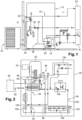
- the combined device 10 comprises a heating water circuit 18 connected to heating elements 20 of a room L, such as radiators.
- the combined device 10 also comprises a first heat exchanger 22 capable of exchanging heat between a heat transfer fluid circuit 24 and the heating water circuit 18.
- the heat transfer fluid circuit 24 exchanges heat between a external environment E to the room L and the heating water circuit 18 present inside the room L.
- an outdoor unit 25 is placed at the level of the external environment E and configured to exchange heat with the circuit heat transfer fluid 24.
- the outdoor unit 25, the heat transfer fluid circuit 24 and the first heat exchanger 22 form a heat pump capable of heating the heating water present in the heating water circuit 18.
- the combined device 10 also comprises a domestic water storage tank 14 and a domestic water circuit 12 in fluid communication with the storage tank 14.
- the circuit sanitary water 12 is connected to sanitary water distribution devices 16, such as taps.
- the combined device 10 further comprises a domestic water heating circuit 26 connected to the heating water circuit 18 in the form of a bypass. Thus, it is the heating water from the heating water circuit 18 which circulates in the domestic water heating circuit 26.
- This domestic water heating circuit 26 comprises a second heat exchanger 28 arranged inside the storage tank 14 to exchange heat with the sanitary water present in the storage tank 14.
- This second heat exchanger 28 is a coil exchanger extending inside the storage tank 14 in the form of a helical winding.
- the sanitary water heating circuit 26 comprises a circuit portion common with the heating water circuit 18. The sanitary water heating circuit 26 is thus in fluid communication with the first 22 and second 28 heat exchangers.
- the sanitary water is therefore heated via two heat exchangers separated by the domestic water heating circuit 26.
- the configuration of this type of combined device 10 makes it possible to heating the heating water directly via the first exchanger 22.
- a three-way valve 30 arranged at a junction between the domestic water heating circuit 26 and the heating water circuit 18 makes it possible to selectively divert the heating water inside the domestic hot water heating circuit 26 to heat the domestic water present in the storage tank 14.
- the configuration of this type of combined device 10 makes it possible to heat the domestic water indirectly through the heating water.
- This indirect domestic water heating configuration involves selective or alternating operation between domestic water heating and domestic water heating. Indeed, under the action of the three-way valve 30 and a circulator 32, the heating water circulates either inside the heating water circuit 18 between the first heat exchanger 22 and the heater 20 is inside the sanitary water heating circuit 26 between the first 22 and the second 28 heat exchangers. In other words, the combined device 10 can only heat the heating water intended for the heating elements 20 or the sanitary water. Thus, the device handset 10 cannot effectively respect the temperature setpoint coming from the heating elements 20 when heating the sanitary water.
- the architecture of the combined device 10 involves the occasional performance of rapid phases for heating the sanitary water to satisfy the needs of the users. These rapid phases of heating the sanitary water involve a significant drop in the energy performance of the heating of the sanitary water, such that this selective or alternate operation is not sufficiently optimized for the heating of the sanitary water.
- the winter period when the demand for heating water is high and often continuous is therefore a period when the performance of the combined device 10 is particularly degraded.
- the difficulties are similar when a heating water request is made while domestic water heating is in progress.
- this configuration of the combined device 10 has disadvantages in terms of compactness. Indeed, the first 22 and second 28 heat exchangers are housed inside the combined device 10 which makes the volume of its outer casing large. In addition, the presence of the second heat exchanger 28 inside the storage tank 14 reduces the interior volume available. This imposes an oversizing of the storage tank 14 for a desired maximum volume of sanitary water inside the storage tank 14. Thus, the storage tank 14 is therefore sized with a larger interior volume compared to a storage tank. storage 14 without heat exchanger within it having the same interior volume available for storage of sanitary water. The number and volume of these components also lead to an increase in the mass of the combined device 10.
- the combined device according to the invention therefore makes it possible to maintain the heating inside a room while having the possibility of producing domestic hot water.
- the possibility of using only a single heat exchanger for the heat exchange with the heating water circuit and the sanitary water circuit makes it possible to reduce the cost of the combined device and its size. This makes it possible to envisage a different installation of the combined device, in particular to be able to suspend it above the ground.
- the heat exchanger is arranged outside the sanitary water storage tank.
- the three pipes of the heat exchanger are concentric.
- each of the three pipes extends along a helical path common to the three pipes.
- a leak cavity is formed within the double wall, the leak cavity being in fluid communication with the exterior of the heat exchanger to allow fluid to escape. escape from the heat exchanger in the event of damage to one of the walls of the double wall.
- the leakage cavity comprises a plurality of channels extending along the three pipes.
- the first pipe has a smooth internal surface.
- the second return line is connected to the first outgoing line by means of a T-fitting.
- the latter further comprises a connection plate for the heating water circuit to a heating water installation of the room and the sanitary water circuit to a sanitary water installation from the premises.
- the domestic water flow and return connectors are mounted on the connection plate, the combined device further comprising at least one flow connector and at least one water return connector mounted on the connection plate to connect the heating water circuit to said local heating water installation.
- the latter comprises a plurality of heating water outlet connectors and a plurality of heating water return connectors connected to the heating water circuit to allow the connection of several heating water installations.
- the latter also comprises a safety connection configured to connect the sanitary water circuit to a safety group making it possible to regulate the pressure inside the storage tank, the safety group being arranged under the storage tank.
- the latter further comprises means for fixing the combined device to a support configured to suspend the combined device above the ground.
- the heat exchanger is arranged below the storage tank or extends around the storage tank.
- a combined device for heating sanitary water and heating water for a room is proposed.
- One embodiment of such a combined device is shown in picture 2 . This embodiment should be considered as an example of the combined device and not as the only possible configuration for the combined device.
- a combined device 50 comprises a sanitary water storage tank 52 and a sanitary water circuit 54 in fluid communication with the storage tank 52.
- the sanitary water circuit 54 is intended to be connected to at least one sanitary water distribution device (not shown).
- the combined device 50 also comprises a heating water circuit 56 intended to be connected to at least one room heater (not shown).
- the combined device 50 also comprises a heat exchanger 58 in which a heat transfer fluid is adapted to circulate via a heat transfer fluid circuit 62.
- the combined device 50 is of preferably coupled to an outdoor unit 60 disposed outside the room.
- the heat exchanger 58, the coolant circuit 62 and the outdoor unit 60 form a heat pump.
- the heat exchanger 58 is configured to perform a heat exchange between the heat transfer fluid and sanitary water present in the sanitary water circuit, and between the heat transfer fluid and heating water present in the heating water circuit.
- the heat exchanger 58 is configured to receive three fluids and to transmit heat to two of these fluids via the heat transfer fluid.
- the heat exchanger 58 thus corresponds to a three-way heat exchanger which makes it possible to carry out a direct heat exchange between the heat transfer fluid and the heating water, but also a direct heat exchange between the heat transfer fluid and the heat transfer fluid. sanitary water.
- the domestic water heating and heating water heating circuits are arranged separately to allow dissociation between the heating of the domestic water and the heating of the heating water.
- the domestic water heating circuit corresponds to a portion of the domestic water circuit 54 putting the storage tank 52 in fluid communication with the heat exchanger 58.
- the heating water heating circuit is merged with the heating water circuit 56.
- the domestic water heating and heating water heating circuits do not include any common pipe portion.
- This separate heating arrangement allows the combined device 50 to have a dedicated loop for heating sanitary water.
- domestic water heating strategies are thus more flexible. Further optimization can therefore be achieved. This is particularly advantageous in terms of user comfort and energy consumption compared to the combined device 10 of the prior art shown in figure 1 .
- this independent configuration of the water heating circuits makes it possible to use the domestic water from the domestic water heating circuit for defrosting the outdoor unit 60.
- the outdoor unit 60 of the heat pump can ice up. This is a normal and expected phenomenon in the operation of the outdoor unit 60.
- the heat pump takes heat from the inside the room to heat the outdoor unit 60.
- This relatively short phenomenon generally less than 15min, can cause discomfort on the user side, on the one hand, and can also lead under certain conditions to a risk of the circuit icing up. water of heater 56 at its interface with the heat transfer fluid.
- This interface is located at the heat exchanger 58 in the embodiment of the figure 2 .
- This phenomenon can damage the heat pump. Thanks to this independent configuration, the domestic water heating circuit can be used at any time to complete or completely carry out a defrosting operation by exchanging heat with the heat transfer fluid. Indeed, the volume of sanitary water present in the sanitary water circuit 54, even when it is at a low temperature, contains enough energy to defrost the outdoor unit 60.
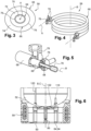
- the heat exchanger 58 comprises according to the invention three pipes nested one inside the other to define three fluid flow zones.
- nested is meant the fact that a first flow zone 70 is placed inside a second flow zone 72 which is itself placed inside a third flow zone 74.
- Said three conduits comprise a first 64, a second 66 and a third 68 conduit forming the first 70, the second 72 and the third 74 fluid flow zones.
- the first 70, second 72 and third 74 flow zones have a circular section extending around a trajectory or a profile A.
- the second 72 and third 74 flow zones are annular.
- the first 64, second 66 and third 68 pipes are concentric so as to obtain three flow zones uniformly distributed around the path A.
- a heat exchange wall 76 is arranged between the first 70 and the second 72 exchange zones as well as between the second 72 and the third 74 exchange zones. These exchange walls 76 correspond to the walls of the first 64 and second 66 pipes. These exchange walls 76 allow the transmission of heat between the two fluids present on either side of the exchange wall 76.
- the first flow zone 70 is formed inside the first pipe 64.
- the second flow zone 72 is formed between the first 64 and second 66 pipes.
- the third flow zone 74 is formed between the second 66 and third 68 conduits.
- the second flow zone 72 is configured to transport the heat transfer fluid from the heat transfer fluid circuit 62.
- each of the first 70 and third 74 flow zones is configured to transport one of the sanitary water and heating water.
- the pipe separating the second flow zone 72 from the flow zone carrying the sanitary water comprises a double wall.
- the sanitary water is further protected from possible contamination.
- the first flow zone 70 is configured to transport sanitary water.
- the wall (67) of the pipe separating the sanitary water from the heat transfer fluid is a double wall.
- a leakage cavity 65 can be formed inside the double wall 67 disposed between the second flow zone 72 of the flow zone transporting sanitary water.
- the figure 13 represents the double wall 67 formed by the first pipe 64.
- the double wall 67 can be made by the second pipe 66 if the sanitary water flows inside the third flow zone 74.
- This leak cavity 65 is in fluid communication with the exterior of the heat exchanger 58 to allow fluid to escape from the heat exchanger 58 in the event of damage to one of the walls of the heat exchanger 58. the double wall 67.
- the fluids inside the heat exchanger 58 are at a pressure greater than the external atmospheric pressure which causes a very rapid exit of the fluid to the outside during a leak.
- the leakage cavity 65 thus makes it possible to detect this damage before any contamination of the sanitary water takes place.
- a leak detection device may be added at the end of the leak cavity 65 to allow a malfunction signal or a combined device shutdown signal to be sent. Rapid detection of damage to one of the walls of the double wall 67 is particularly important for safety reasons, in particular in connection with the regulations of certain countries.
- standard EN 12897 provides that the leak created by a 2 mm hole in one of the walls of the double wall 67 must be able to be detected within 300 seconds.
- the double wall 67 is preferably formed by an internal wall 69 and an external wall 71 inserted one inside the other.
- Leakage cavity 65 is disposed between inner 69 and outer 71 walls.
- Leakage cavity 65 may include a plurality of channels 73 extending along first 64, second 66 and third 68 conduits.
- the channels 73 can be formed by grooves or ribs provided on the surface of the inner 69 and/or outer 71 walls.
- the channels 73 are preferably parallel to a mean line along which the first conduit 64 extends.
- the channels 73 can extend locally in a direction transverse to this average line, for example with a helical trajectory developing around the average line.
- the channels 73 are spaced around the middle line by a distance less than or equal to 2 mm.
- the pipe in which the sanitary water circulates is particularly prone to scaling, which can ultimately reduce the performance of the installation and damage it. It has been observed that the reduction of obstacles or reliefs inside the pipe makes it possible to significantly prevent the deposition of scale inside the pipe.
- the internal surface of the first conduit 64 is preferably smooth. “Smooth” is understood to mean an internal surface devoid of grooves, corrugations or added element inside the first pipe 64 which would form an obstacle to the flow of sanitary water and having the lowest possible roughness.
- the internal surface of the first pipe 64 preferably has a roughness equal to or less than 0.010 mm.
- the first pipe 64 can be made of copper or a copper alloy to limit the deposition of scale, copper being a material having a lower natural roughness than the other materials that can be used in this application.
- this first pipe 64 comprises a copper tube whose internal surface is smooth so as to be very robust against scaling.
- the inner surface of the inner wall 69 is preferably smooth and/or comprises copper.
- the trajectory or profile A is preferably helical, as shown on the figure 4 .
- the first 64, second 66 and third 68 pipes preferably extend around themselves along a longitudinal axis B.
- the first 64, second 66 and third 68 pipes preferably extend along a helical path A common to the three pipes.
- the first 70, second 72 and third 74 flow zones are preferably connected to the heat transfer fluid circuit 62, to the heating water circuit 56 and to the sanitary water circuit 54 via exchanger connections 78 arranged at the level of the ends of the first 64, second 66 and third 68 pipes.
- the heat exchanger 58 is preferably arranged outside the sanitary water storage tank 52.
- the sanitary water circuit 54 comprises a first sanitary water circuit 80 intended to put the storage tank 52 in fluid communication with the heat exchanger 58 and a second sanitary water circuit 82 intended to put the storage tank 52 in fluid communication with the distribution members of a sanitary water installation.
- the first sanitary water circuit 80 corresponds to a sanitary water heating circuit.
- the first sanitary water circuit 80 comprises a first flow pipe 84 connecting the storage tank 52 to a sanitary water inlet of the heat exchanger 58 and a first return pipe 86 connecting a sanitary water outlet from the heat exchanger 58 to the storage tank 52.
- the first flow line 84 and the first return line 86 are each connected to one end of the first flow zone 70 of the heat exchanger 58 via the exchanger fittings 78.
- the latter also comprises a first circulator 88.
- the first sanitary water circuit 80 forms a circuit domestic water heating.
- the combined device 50 further comprises a controller 87 configured to regulate the speed of the first circulator 88 so as to regulate the flow rate of sanitary water circulating in the first sanitary water circuit 80.
- the controller 87 is also configured to regulate the flow of heat transfer fluid.
- the simultaneous or selective regulation of the flow rate of circulation of the sanitary water and of the heat transfer fluid makes it possible to regulate the temperature of the sanitary water supplied to the storage tank 52.
- the controller 87 makes it possible to optimize the performance during heating or to guarantee the resistance of the exchanger over time (for example, avoiding the risk of ice formation).
- the second sanitary water circuit 82 comprises a second outlet pipe 90 connecting the storage tank 52 to a sanitary water outlet connection 92.
- This second outlet pipe 90 can otherwise be considered as a water outlet pipe hot out of the tank to a sanitary water installation (not shown).
- This sanitary water installation comprises in particular the sanitary water distribution members mentioned above.
- the second sanitary water circuit 82 also comprises a second return pipe 94 connected to a sanitary water return connection 96.
- the second return pipe 94 places the storage tank 52 in fluid communication with this return connection.
- sanitary water 96 This second outgoing pipe 90 can otherwise be considered as a cold water return pipe coming from a sanitary water source of the sanitary water installation.
- This cold water preferably corresponds to the water supplied by the running water distribution network of the locality.
- the temperature of this water is generally between 5 to 25° C. at the level of the combined device 50.
- the second return pipe 94 is connected to the first flow pipe 84 by means of a T-piece 98.
- the second return pipe 94 is indirectly connected to the storage tank 52 via the first outgoing pipe 84.
- the term "T-piece” is understood to mean a pipe portion having three orifices in fluid communication with each other.
- tee fitting 98 includes a first port in fluid communication with storage tank 52, a second port in fluid communication with heat exchanger 58, and a third port in fluid communication with the second return line. 94.
- the second outgoing pipe 90, the first return pipe 86 and the pipe portion between the storage tank 52 and the tee fitting 98 are connected to the tank. storage tank 52 preferably in a lower part of the storage tank 52. Such an arrangement is for example visible on the figure 6 And 8 .
- the second outgoing pipe 90, the first return pipe 86 and the pipe portion between the storage tank 52 and the T-fitting 98 are connected to the storage tank 52 preferably in an upper part of the storage tank 52.
- the heating water circuit 56 comprises a heating water return line 100 connecting a heating water return fitting 102 to an inlet of the heat exchanger 58.
- the heating water circuit 56 comprises also a heating water outlet pipe 104 connecting a heating water outlet connection 106 to an outlet of the heat exchanger 58.
- the heating water return pipe 100 and the heating water outlet 104 are each connected to one end of the third flow zone 74 of the heat exchanger 58 via the exchanger connections 78.
- the heating water circuit 56 also includes a second circulator 108.
- the controller 87 is further configured to regulate the speed of the second circulator 108 so as to regulate the flow rate of the heating water circulating in the heating water circuit 56.
- the simultaneous or selective regulation of the flow rate of circulation of the heating water and heat transfer fluid regulates the temperature of the heating water and the power supplied to the heating installation.
- the sanitary water installation is connected to the combined device 50 via the outlet 92 and return 96 connections for sanitary water.
- the room heating installation is connected to the combined device 50 via the flow 106 and return 102 connections for heating water.
- the storage flask 52 is preferably a cannulated flask.
- the storage tank 52 is connected to the first 80 and second 82 sanitary water circuits by means of nozzles arranged inside the storage tank 52.
- the use of nozzles makes it possible in particular to arrange the inlets or outlets of the first 80 and second 82 sanitary water circuits at predetermined positions inside the storage tank 52.
- the storage tank 52 therefore does not contain no heat exchanger, in particular no coil-type heat exchanger.
- the volume available inside the storage tank 52 is thus greater than in the case of a coil tank for the same external volume of the storage tank 52. Indeed, the "dead" or unavailable volume located at the location of the coil and below it is not present here.
- the storage tank 52 preferably has an interior volume less than or equal to 150 dm3, preferably less than or equal to 100 dm3.
- the combined device 10 of the prior art is generally used with a storage tank 12 having an interior volume, before installation of the coil, of 190 dm3. This allows the combination device 52 to be more compact and have a lower manufacturing cost than the combination device 10 of the prior art.
- a coil heat exchanger is much bulkier/heavier than a heat exchanger external to the storage tank 52.
- the water in the storage tank 52 is heated by natural convection . You therefore need a very large heat exchanger to have acceptable performance. Conversely, the water is heated by forced convection with an external heat exchanger, which significantly increases the performance of the exchange.
- This configuration comprising a storage balloon 52 with cannulas allows the combined device 50 to have a maximum height along a longitudinal axis of extension C of the storage balloon 52 less than or equal to 150 cm, preferably less than or equal to 145cm.
- the storage balloon 52 comprises a combined cannula 118, a suction cannula 120 as well as a discharge cannula 122 all opening inside the storage balloon 52.
- the combination cannula 118 is configured to be connected to the first outgoing line 84.
- the second return line 94 is connected to the first outgoing line 84 by means of a tee fitting so that the discharge into the storage tank 52 of sanitary water from the second return pipe 94 is carried out through the combined cannula 118.
- the combined cannula 118 extends inside the storage tank 52 so that its end orifice opens at the level of a lower part of the storage tank 52.
- the combined cannula 118 is configured to operate either in suction or in discharge depending on the mode of operation of the sanitary water circuit 54.
- the suction cannula 118 is configured to draw cold water from the lower part of the storage tank 52 during a heating phase of the sanitary water, i.e. when there is circulation of the sanitary water inside the first circuit of sanitary water 80.
- the suction cannula 118 is configured to discharge sanitary water inside the storage tank 52 during a withdrawal of sanitary water via the second suction cannula 120, i.e. when there is circulation of sanitary water inside the second sanitary water circuit 82.
- the combined cannula 118 preferably comprises a jet aerator to allow the suction or the discharge of the sanitary water in a direction transverse to the longitudinal axis of extension C of the storage tank 52.
- the jet aerator can be formed on the combined cannula 118 by obstructing its distal end and by forming one or more lateral orifices on a peripheral wall of the combined cannula 118. This makes it possible to reduce the mixing caused by the backflow of the sanitary water coming from the second return line 94 when the latter is made along the longitudinal axis of extension C of the storage balloon 52.
- the discharge cannula 122 also preferably includes a jet aerator at its distal end, i.e. the end where the water is forced back into the storage tank 52.
- the combined device 50 can be devoid of a T-fitting so that each of the first outgoing pipe 84 and second return line 94 open distinctly inside the storage tank 52.
- the combined cannula 118 functions only as a suction cannula and an additional discharge cannula is arranged at the end of the second return line 94.
- the suction cannula 120 is configured to be connected to the second starting pipe 90.
- the suction cannula 120 extends inside the storage balloon 52 so that its end orifice opens at the level of an upper part of the storage tank 52.
- the suction cannula 122 is configured to suck hot water from the upper part of the storage tank 52.
- the discharge cannula 122 is configured to be connected to the first return pipe 86. To obtain a good compromise between performance and user comfort, the distal end of the discharge cannula 122 is located at an intermediate or median position. the height of the internal cavity of the storage tank 52. Indeed, positioning too close to the upper part of the storage tank 52 would lead to mixing of this upper part. This brewing is harmful because it does not make it possible to keep a reserve of hot water in the event of an unexpected draw-off occurring. Additionally, positioning too close to the bottom of the storage balloon 52, and therefore the combination cannula 118, would result in a drop in performance.
- the distal end of the delivery cannula 122 is located at a position distant from the upper wall of the storage balloon 52 by at least 20% of the height of the internal cavity of the storage balloon 52 and distant from the lower wall of the storage balloon 52 at least 20% of the height of the internal cavity of the storage balloon 52.
- the distal end of the delivery cannula 122 is located between 20% and the height of the internal cavity of the storage balloon 52.
- the distal end of the delivery cannula 122 can be located between 30% and 70% of the height of the internal cavity of the storage balloon 52.
- the distal end of the delivery cannula 122 is preferably located at about 50% of the height of the internal cavity of the storage tank 52.
- the sanitary water is taken from the lower part of the storage tank 52 to be heated in the heat exchanger 58, i.e. the part of the storage tank 52 where the cold water is discharged by the second return pipe 94. Consequently, even if the ball is not entirely cold, performance will not be degraded. Thus, efficient heating can be carried out without risking a situation of discomfort for the user. This is due to the fact that it is possible, if necessary, to supply the heating water circuit 56 without however cutting off the heating of the sanitary water. It is therefore possible to make optimized heating without being constrained by the heating water circuit 56.
- the temperature of the sanitary water immediately reduces at the inlet of the heat exchanger 58 which reduces the condensation temperature inside the storage tank 52.
- the coefficient of performance of the heat pump is therefore improved.
- this withdrawal will have a very low impact on the average performance of the domestic water heater.
- the domestic water heating phases can thus be longer than in the case of a coil tank for better performance.
- the combined device 50 may include means 110 for attaching the combined device to a support 112 configured to suspend the combined device 50 above the ground.
- the term "suspend” means that the weight of the combined device 50 is supported by the support 112 in its entirety.
- the support 112 is preferably a wall of the room.
- the known combined devices are generally “on a base”, ie placed on the ground, because their mass does not allow suspension on a support to be envisaged.
- the reduction in the mass of the combined device 50 makes it possible to consider a solution suspended from the support 112 via the fixing means 110.
- a suspended solution makes it possible to reduce the surface taken up on the ground by the combined device 50, which corresponds to a current expectation users, particularly in the construction of new housing.
- the fixing means preferably comprise an interface structure between the support 112 and modules formed by the combined device 50.
- This interface structure is for example a frame or a ladder fixed to the wall or to the support 112 on which the combined device 50 is suspended.
- This interface structure allows the distribution of the forces on the support 112 to facilitate and sustain the installation of the combined device 50. Indeed, a wall can be non-bearing and therefore not very suitable for supporting heavy suspended loads.
- the combined device 50 when filled with water, weighs more than 200 kg.
- the heat exchanger 58 is arranged below the storage tank 52, as illustrated in the figure 6 .
- This configuration makes it possible to reduce the transverse dimensions to the longitudinal axis of extension C of the combined device 50 compared to a configuration where the heat exchanger 58 extends around the storage tank 52.
- the external dimensions of the heat exchanger 58 are preferably less than or equal to the external dimensions of the storage tank 52.
- the transverse size of the combined device 50 is substantially constant along the longitudinal axis of extension C.
- the external dimensions of the heat exchanger 58 can be greater than the external dimensions of the storage tank 52.
- FIG. 7 shows a configuration of the combined device 50 in which the heat exchanger 58 is arranged so as to extend around the storage tank 52.
- the heat exchanger 58 and the storage tank 52 are preferably concentric.
- the longitudinal axis B of the heat exchanger 58 coincides with the longitudinal extension axis C of the storage tank 52.
- the combined device 50 comprises a connection plate 124 of the heating water circuit 56 to a local heating water installation and of the sanitary water circuit 54 to a local sanitary water installation.
- a connection plate 124 is visible on the figure 8 , 9 , 11 And 12 .
- the outlet 92 and return 96 connections for sanitary water are mounted on the connection plate 124 to connect the sanitary water circuit 54 to the sanitary water installation of the room.
- the heating water flow 106 and return 102 fittings are mounted on the connection plate 124 to connect the heating water circuit 56 to the heating water installation of the premises.
- all of the connections for the domestic water 54 and heating water 56 circuits are arranged at the same interface.
- connection plate 124 makes it possible to know prior to the installation of the combined device 50 the position of each of the connections. This is particularly useful when the combined device 50 is intended to be installed in a new building because the installation of the heating water and sanitary water installations of the room can be carried out before the installation of the combined device 50. Connection plate 124 therefore allows great flexibility in setting up these installations as well as the combined device 50.
- connection plate 124 allows the use of many components already used for wall-mounted boilers, which makes it possible to reduce the manufacturing cost of the combined device 50.
- connection plate 124 is preferably arranged below the storage tank 52 to improve its accessibility, in particular to an installer.
- the connection plate 124 is preferably arranged at the rear of the combined device 52. This position behind the connection plate 124 allows it to be fixed to a support.
- the connection plate 124 can be arranged at and/or under the fixing means 110.
- connection plate 124 is preferably formed by an elongated plate comprising a plurality of orifices capable of receiving a plurality of connectors.
- the connection plate 124 can also include dedicated fixing means 126 to allow the fixing of the connection plate to the support 112 or to any other support.
- the combined device 50 may also include a safety fitting 129 configured to connect the domestic water circuit 54 to a safety group 128.
- the safety group 128 is connected between the T-piece fitting 98 and the sanitary water return 96.
- This safety group makes it possible to regulate the pressure inside the storage tank 52.
- a safety group must be installed on the cold water inlet (or pipe domestic water return) of a domestic water storage tank.
- the safety unit often involves laborious installation and can be very bulky in addition to the volume occupied by the combined device 50. The simplification of its installation is therefore a significant benefit for its installer.
- the installation of this safety group is here simplified by the presence of the safety connection 129 allowing the assembly of a safety group 128 according to the needs of the user.
- the combined device 50 can be configured to be connected to a multi-zone heating kit making it possible to connect the combined device 50 to several heating water circuits.
- a multi-zone heating kit 136 is shown in the figure 12 .
- This multi-zone heating kit 136 allows the temperature to be regulated selectively in several zones of the room, in particular in two distinct zones.
- the multizone heating kit 136 can be installed initially, ie as standard, or later as an accessory on the combined device 50.
- the combined device 50 can include an additional connector 132 and an additional heating water return 134 connection arranged on the connection plate 124.
- the combined device 50 may also include a backflow preventer 140 to fill the heating water circuit 56 with water from the city water distribution network at the time of commissioning, while preventing water from the heating water circuit 56 from entering this distribution network.
- Backflow preventer 140 is placed between heating water return pipe 100 and second return pipe 94.
- backflow preventer 140 is preferably placed between the heating water return connector 102 and the sanitary water return connector 96. Even more preferably, the backflow preventer is mounted on the connection plate 124 at the same level as the other connectors to improve its accessibility.
- the combined device 50 can advantageously be structured in a modular manner.
- the combined device 50 can be structurally divided into predefined subsets.
- the sub-assemblies or modules have a mass less than or equal to 55 kg when they are empty of water, preferably less than or equal to 50 kg, more preferably less than or equal to 45 kg.
- This modular structure makes it possible to advantageously distribute the mass of the combined device 50 into several interconnectable modules. This distribution is preferably carried out so that an installer can carry and maneuver each of the modules alone.
- the combined device 50 comprises a first module 114 comprising the sanitary water storage tank 52 and a second module 116 comprising the heat exchanger 58, the heating water circuits 56 and sanitary water 54 as well as the connection plate 124.
- the fixing means 110 are preferably configured to fix to the support 112 the first 114 and second 116 modules independently of one another.
- the fixing means 110 can comprise first means for fixing the first module 114 to the support 112 and second means for fixing the second module 116 to the support 112.
- a method of mounting the combined device 50 includes fixing the first module 114 to the support 112 so as to suspend the first module 114 above the ground.
- the first 114 and second 116 modules are then positioned relative to each other.
- the method also comprises fixing the second module 116 on the support 112 so as to suspend the second module 116 above the ground.
- the second module 116 can alternatively be fixed only to the first module 114 so to be suspended above the ground. In the latter case, the weight of the second module 116 is taken up in whole or in part by the first module 114.
- the assembly process can be started by fixing the second module 116.
- the first 114 and second 116 modules are then positioned relative to each other.
- the first module 114 is fixed to the support 112 so as to suspend the first module 114 above the ground.
- the first module 114 can alternatively be fixed only to the second module 116 so as to rest on the second module 116. In the latter case, the weight of the first module 114 is taken up in whole or in part by the second module 116.
- the heating system also comprises at least one sanitary water installation comprising at least one point of drawing and at least one heating water installation comprising at least one heat emission system for heating the room. Said at least one sanitary water installation and at least one heating water installation are respectively connected to the sanitary water circuit 54 and to the heating water circuit 56 of the combined device 50.
Claims (15)
- Kombigerät (50) zum Erhitzen von Brauchwasser und Heizwasser eines Raums, wobei das Kombigerät (50) Folgendes umfasst:- einen Speicherbehälter (52) von Brauchwasser,- einen Brauchwasserkreislauf (54) in fluidischer Kommunikation mit dem Speicherbehälter (52),- einen Heizwasserkreislauf (56),- einen Wärmetauscher (58) einer Wärmepumpe, in dem eine Wärmeträgerflüssigkeit ausgelegt ist, um zu zirkulieren, wobei der Wärmetauscher (58) konfiguriert ist, um einen Wärmetausch durchzuführen:- zwischen der Wärmeträgerflüssigkeit und dem Brauchwasser, das im Brauchwasserkreislauf (54) vorhanden ist, und- zwischen der Wärmeträgerflüssigkeit und dem Heizwasser, das im Heizwasserkreislauf (56) vorhanden ist,wobei der Wärmetauscher (58) drei Leitungen (64, 66, 68) umfasst, die ineinandergeschoben sind, um drei Abflussbereiche (70, 72, 74) von Fluid zu definieren,wobei die drei Leitungen (64, 66, 68) eine erste (64), eine zweite (66) und eine dritte (68) Leitung umfassen, die Folgendes bilden:- einen ersten Abflussbereich (70) im Inneren der ersten Leitung (64),- einen zweiten Abflussbereich (72) mit ringförmigem Schnitt, der zwischen der ersten Leitung (64) und der zweiten Leitung (66) angeordnet ist, und- einen dritten Abflussbereich (74) mit ringförmigem Schnitt, der zwischen der zweiten Leitung (66) und der dritten Leitung (68) angeordnet ist,wobei der zweite Abflussbereich (72) konfiguriert ist, um die Wärmeträgerflüssigkeit zu transportieren, und jeder des ersten (70) und dritten (74) Abflussbereichs konfiguriert ist, um eines vom Brauchwarmwasser und Heizwasser zu transportieren,dadurch gekennzeichnet, dass die Wand (67) der Leitung, die das Brauchwasser von der Wärmeträgerflüssigkeit trennt, eine doppelte Wand ist.
- Kombigerät (50) nach Anspruch 1, wobei der Wärmetauscher (58) außerhalb des Speicherbehälters (52) von Brauchwasser angeordnet ist.
- Kombigerät (50) nach Anspruch 1 oder 2, wobei die drei Leitungen (64, 66, 68) des Wärmetauschers (58) konzentrisch sind.
- Kombigerät (50) nach einem der Ansprüche 1 bis 3, wobei sich jede der drei Leitungen (64, 66, 68) entlang einer schraubenförmigen Bahn (A) erstreckt, die den drei Leitungen gemeinsam ist.
- Kombigerät (40, 50) nach einem der vorhergehenden Ansprüche, wobei ein Auslaufhohlraum im Inneren der doppelten Wand gebildet ist, wobei der Auslaufhohlraum in fluidischer Kommunikation mit der Außenseite des Wärmetauschers (58) ist, um einem Fluid zu ermöglichen, im Fall einer Beschädigung einer der Wände der doppelten Wand aus dem Wärmetauscher (58) auszutreten.
- Kombigerät (50) nach Anspruch 5, wobei der Auslaufhohlraum eine Vielzahl von Kanälen umfasst, die sich entlang der drei Leitungen (64, 66, 68) erstrecken.
- Kombigerät (50) nach einem der vorhergehenden Ansprüche, wobei die erste Leitung (64) eine glatte innere Fläche umfasst.
- Kombigerät (50) nach einem der vorhergehenden Ansprüche, wobei der Brauchwasserkreislauf (54) Folgendes umfasst:- einen ersten Brauchwasserkreislauf (80), umfassend eine erste Ausgangsleitung (84), die den Speicherbehälter (52) mit einem Brauchwassereingang des Wärmetauschers (58) verbindet, und eine erste Rücklaufleitung (86), die einen Brauchwasserausgang des Wärmetauschers (58) mit dem Speicherbehälter (52) verbindet,- einen zweiten Brauchwasserkreislauf (82), umfassend eine zweite Ausgangsleitung (90), die den Speicherbehälter mit einer Ausgangsverbindung von Brauchwasser (92) verbindet, die konfiguriert ist, um mit einer Brauchwasseranlage verbunden zu werden, und eine zweite Rücklaufleitung (94), die mit einer Rücklaufverbindung von Brauchwasser (96) verbunden ist, die konfiguriert ist, um mit einer Brauchwasseranlage verbunden zu sein.
- Kombigerät (50) nach Anspruch 8, wobei die zweite Rücklaufleitung (94) mit der ersten Ausgangsleitung (84) mit Hilfe einer T-förmigen Verbindung (98) verbunden ist.
- Kombigerät 50) nach einem der vorhergehenden Ansprüche, umfassend außerdem eine Platine zur Verbindung (124) des Heizwasserkreislaufs (56) mit einer Heizwasseranlage des Raums und des Brauchwasserkreislaufs (54) mit einer Brauchwasseranlage des Raums.
- Kombigerät (50) nach Anspruch 8 in Kombination mit Anspruch 10, wobei die Ausgangs- (92) und Rücklaufverbindungen (96) von Brauchwasser auf der Verbindungplatine (124) montiert sind, wobei das Kombigerät (50) außerdem mindestens eine Ausgangsverbindung (106) und mindestens eine Rücklaufverbindung (102) von Heizwasser umfasst, die auf der Verbindungplatine (124) montiert sind, um den Heizwasserkreislauf (56) mit der Heizwasseranlage des Raums zu verbinden.
- Kombigerät (50) nach Anspruch 11, umfassend eine Vielzahl von Ausgangsverbindungen von Heizwasser (106, 132) und eine Vielzahl von Rücklaufverbindungen von Heizwasser (102, 134), die mit dem Heizwasserkreislauf (56) verbunden sind, um die Verbindung von mehreren Heizwasseranlagen zu ermöglichen.
- Kombigerät (50) nach einem der vorhergehenden Ansprüche, umfassend auch eine Sicherheitsverbindung (129), die den Brauchwasserkreislauf (54) mit einer Sicherheitsgruppe (128) verbindet, die ermöglicht, den Druck im Inneren des Speicherbehälters (52) zu regulieren, wobei die Sicherheitsgruppe (128) unter dem Speicherbehälter (52) angeordnet ist.
- Kombigerät (50) nach einem der vorhergehenden Ansprüche, wobei der Wärmetauscher (58) unter dem Speicherbehälter (52) angeordnet ist oder sich um den Speicherbehälter (52) herum erstreckt.
- System zum Erhitzen von Brauchwasser und Heizwasser eines Raums, umfassend:- ein Kombigerät (50) nach einem der vorhergehenden Ansprüche,- mindestens eine Brauchwasseranlage, umfassend mindestens einen Entnahmepunkt und mindestens einer Heizwasseranlage, umfassend mindestens ein System zur Emission von Wärme, um den Raum zu heizen, die jeweils mit dem Brauchwasserkreislauf (54) und mit dem Heizwasserkreislauf (56) des Kombigeräts (50) verbunden sind.
Applications Claiming Priority (1)
| Application Number | Priority Date | Filing Date | Title |
|---|---|---|---|
| FR1859290A FR3086995B1 (fr) | 2018-10-08 | 2018-10-08 | Dispositif combine de chauffage de l'eau sanitaire et de l'eau de chauffage d'un local avec echangeur de chaleur trois fluides |
Publications (2)
| Publication Number | Publication Date |
|---|---|
| EP3637014A1 EP3637014A1 (de) | 2020-04-15 |
| EP3637014B1 true EP3637014B1 (de) | 2023-04-05 |
Family
ID=65244172
Family Applications (1)
| Application Number | Title | Priority Date | Filing Date |
|---|---|---|---|
| EP19201102.1A Active EP3637014B1 (de) | 2018-10-08 | 2019-10-02 | Kombiheizgerärt zum erhitzen von brauchwasser und heizwasser eines raums mit drei-wege-wärmetauscher |
Country Status (5)
| Country | Link |
|---|---|
| EP (1) | EP3637014B1 (de) |
| ES (1) | ES2947632T3 (de) |
| FR (1) | FR3086995B1 (de) |
| PL (1) | PL3637014T3 (de) |
| PT (1) | PT3637014T (de) |
Family Cites Families (4)
| Publication number | Priority date | Publication date | Assignee | Title |
|---|---|---|---|---|
| JPH01256754A (ja) * | 1988-04-04 | 1989-10-13 | Sun Wave Ind Co Ltd | 冷暖房・給湯システム |
| FR2725011B1 (fr) * | 1994-09-23 | 1997-08-08 | Financ & Comm Chablais | Ensemble d'equipements pour installation combinee de chauffage et de production d'eau chaude sanitaire |
| JP5305714B2 (ja) * | 2008-04-03 | 2013-10-02 | シャープ株式会社 | 給湯暖房システム |
| JP6013264B2 (ja) * | 2013-04-26 | 2016-10-25 | リンナイ株式会社 | 貯湯システム |
-
2018
- 2018-10-08 FR FR1859290A patent/FR3086995B1/fr active Active
-
2019
- 2019-10-02 PL PL19201102.1T patent/PL3637014T3/pl unknown
- 2019-10-02 PT PT192011021T patent/PT3637014T/pt unknown
- 2019-10-02 EP EP19201102.1A patent/EP3637014B1/de active Active
- 2019-10-02 ES ES19201102T patent/ES2947632T3/es active Active
Also Published As
| Publication number | Publication date |
|---|---|
| PL3637014T3 (pl) | 2023-08-14 |
| FR3086995B1 (fr) | 2021-01-15 |
| EP3637014A1 (de) | 2020-04-15 |
| ES2947632T3 (es) | 2023-08-14 |
| PT3637014T (pt) | 2023-06-26 |
| FR3086995A1 (fr) | 2020-04-10 |
Similar Documents
| Publication | Publication Date | Title |
|---|---|---|
| EP3637013B1 (de) | Kombiheizgerät zum gleichzeitigen erhitzen von brauchwasser und dem heizwasser eines raums | |
| CA2875216A1 (fr) | Dispositif de stockage d'energie thermique | |
| EP3637012B1 (de) | Wandkombiheizgerärt zum erhitzen von brauchwasser und heizwasser eines raums | |
| WO2006105668A1 (fr) | Chaudière avec anti-chambre et échangeur hélicoïdal | |
| EP3637014B1 (de) | Kombiheizgerärt zum erhitzen von brauchwasser und heizwasser eines raums mit drei-wege-wärmetauscher | |
| FR2733822A1 (fr) | Module de distribution pour installation de chauffage central avec plancher chauffant et radiateurs | |
| WO2000050832A1 (fr) | Echangeur thermique a plaques, a vanne integree | |
| FR2927153A1 (fr) | Dispositif combine de climatisation. | |
| FR3048763B1 (fr) | Systeme de rafraichissement, climatisation ou chauffage a unites separees et caisson renfermant l'une des unites | |
| FR2724220A1 (fr) | Refrigerant atmospherique humide a dispositif antigel | |
| WO2009050396A2 (fr) | Installation de chauffage comportant un ballon de distribution | |
| EP1450109A1 (de) | Kombinierte Solarheizungsanlage mit Überhitzungsverwaltung und Verfahren zur Regulierung der Anlage. | |
| EP1420129A1 (de) | Heizungssystem für ein Schwimmbecken | |
| EP4124818B1 (de) | Verbindungsvorrichtung und system zur wassererwärmung durch wärmerückgewinnung aus abwasser | |
| FR2587790A1 (fr) | Dispositif modulaire permettant le stockage thermique a partir d'au moins deux sources energetiques, dont l'une est intermittente, et installation utilisant un tel dispositif | |
| EP0138682A2 (de) | Gerät zur Speicherung von Wärme aus zwei Energiebrunnen und Installation zum Gebrauch dieses Geräts | |
| FR2969260A1 (fr) | Systeme de production d'eau chaude sanitaire a l'aide de capteurs solaires thermiques a eau, dans lequel un meme circuit met en relation un ballon d'eau chaude et les capteurs. | |
| FR3103884A1 (fr) | Cuve de stockage compacte et ensemble chauffe-eau sanitaire | |
| EP0549437B1 (de) | Heizkreislauf oder dergleichen mit heissem Wasser sowie die Komponenten desselben | |
| CA2411703A1 (fr) | Unite de chauffage de fluide caloporteur pour installation de chauffage central | |
| EP2734787B1 (de) | Verfahren zur warmawassererzeugung durch die verwendung von solarpanäle und mit einer vorrichtun zum schutz vor dem überhitzung | |
| WO2020229368A1 (fr) | Systeme d'interconnexion hydraulique pour reseau thermique | |
| FR2737282A1 (fr) | Bouteille d'homogeneisation pour installation de chauffage avec plancher chauffant | |
| FR2715462A1 (fr) | Sous-station pour installation combinée de chauffage et de production d'eau chaude sanitaire à partir d'une chaufferie. | |
| WO2013017798A2 (fr) | Dispositif de chauffage d'une eau de bassin |
Legal Events
| Date | Code | Title | Description |
|---|---|---|---|
| PUAI | Public reference made under article 153(3) epc to a published international application that has entered the european phase |
Free format text: ORIGINAL CODE: 0009012 |
|
| STAA | Information on the status of an ep patent application or granted ep patent |
Free format text: STATUS: THE APPLICATION HAS BEEN PUBLISHED |
|
| AK | Designated contracting states |
Kind code of ref document: A1 Designated state(s): AL AT BE BG CH CY CZ DE DK EE ES FI FR GB GR HR HU IE IS IT LI LT LU LV MC MK MT NL NO PL PT RO RS SE SI SK SM TR |
|
| AX | Request for extension of the european patent |
Extension state: BA ME |
|
| STAA | Information on the status of an ep patent application or granted ep patent |
Free format text: STATUS: REQUEST FOR EXAMINATION WAS MADE |
|
| 17P | Request for examination filed |
Effective date: 20201014 |
|
| RBV | Designated contracting states (corrected) |
Designated state(s): AL AT BE BG CH CY CZ DE DK EE ES FI FR GB GR HR HU IE IS IT LI LT LU LV MC MK MT NL NO PL PT RO RS SE SI SK SM TR |
|
| REG | Reference to a national code |
Ref country code: DE Ref legal event code: R079 Ref document number: 602019027123 Country of ref document: DE Free format text: PREVIOUS MAIN CLASS: F24H0001520000 Ipc: F24H0009130000 |
|
| GRAP | Despatch of communication of intention to grant a patent |
Free format text: ORIGINAL CODE: EPIDOSNIGR1 |
|
| STAA | Information on the status of an ep patent application or granted ep patent |
Free format text: STATUS: GRANT OF PATENT IS INTENDED |
|
| RIC1 | Information provided on ipc code assigned before grant |
Ipc: F24D 3/08 20060101ALI20221013BHEP Ipc: F24H 4/04 20060101ALI20221013BHEP Ipc: F28D 7/14 20060101ALI20221013BHEP Ipc: F28D 7/10 20060101ALI20221013BHEP Ipc: F24D 19/10 20060101ALI20221013BHEP Ipc: F24D 17/02 20060101ALI20221013BHEP Ipc: F24D 17/00 20060101ALI20221013BHEP Ipc: F24D 3/18 20060101ALI20221013BHEP Ipc: F24H 9/06 20060101ALI20221013BHEP Ipc: F24H 1/52 20060101ALI20221013BHEP Ipc: F24H 9/13 20220101AFI20221013BHEP |
|
| INTG | Intention to grant announced |
Effective date: 20221109 |
|
| GRAS | Grant fee paid |
Free format text: ORIGINAL CODE: EPIDOSNIGR3 |
|
| GRAA | (expected) grant |
Free format text: ORIGINAL CODE: 0009210 |
|
| STAA | Information on the status of an ep patent application or granted ep patent |
Free format text: STATUS: THE PATENT HAS BEEN GRANTED |
|
| AK | Designated contracting states |
Kind code of ref document: B1 Designated state(s): AL AT BE BG CH CY CZ DE DK EE ES FI FR GB GR HR HU IE IS IT LI LT LU LV MC MK MT NL NO PL PT RO RS SE SI SK SM TR |
|
| REG | Reference to a national code |
Ref country code: GB Ref legal event code: FG4D Free format text: NOT ENGLISH |
|
| REG | Reference to a national code |
Ref country code: DE Ref legal event code: R096 Ref document number: 602019027123 Country of ref document: DE |
|
| REG | Reference to a national code |
Ref country code: CH Ref legal event code: EP |
|
| REG | Reference to a national code |
Ref country code: AT Ref legal event code: REF Ref document number: 1558508 Country of ref document: AT Kind code of ref document: T Effective date: 20230415 |
|
| REG | Reference to a national code |
Ref country code: IE Ref legal event code: FG4D Free format text: LANGUAGE OF EP DOCUMENT: FRENCH |
|
| REG | Reference to a national code |
Ref country code: PT Ref legal event code: SC4A Ref document number: 3637014 Country of ref document: PT Date of ref document: 20230626 Kind code of ref document: T Free format text: AVAILABILITY OF NATIONAL TRANSLATION Effective date: 20230621 |
|
| P01 | Opt-out of the competence of the unified patent court (upc) registered |
Effective date: 20230530 |
|
| REG | Reference to a national code |
Ref country code: SE Ref legal event code: TRGR Ref country code: LT Ref legal event code: MG9D |
|
| REG | Reference to a national code |
Ref country code: NL Ref legal event code: FP |
|
| REG | Reference to a national code |
Ref country code: ES Ref legal event code: FG2A Ref document number: 2947632 Country of ref document: ES Kind code of ref document: T3 Effective date: 20230814 |
|
| PG25 | Lapsed in a contracting state [announced via postgrant information from national office to epo] |
Ref country code: NO Free format text: LAPSE BECAUSE OF FAILURE TO SUBMIT A TRANSLATION OF THE DESCRIPTION OR TO PAY THE FEE WITHIN THE PRESCRIBED TIME-LIMIT Effective date: 20230705 |
|
| PG25 | Lapsed in a contracting state [announced via postgrant information from national office to epo] |
Ref country code: RS Free format text: LAPSE BECAUSE OF FAILURE TO SUBMIT A TRANSLATION OF THE DESCRIPTION OR TO PAY THE FEE WITHIN THE PRESCRIBED TIME-LIMIT Effective date: 20230405 Ref country code: LV Free format text: LAPSE BECAUSE OF FAILURE TO SUBMIT A TRANSLATION OF THE DESCRIPTION OR TO PAY THE FEE WITHIN THE PRESCRIBED TIME-LIMIT Effective date: 20230405 Ref country code: LT Free format text: LAPSE BECAUSE OF FAILURE TO SUBMIT A TRANSLATION OF THE DESCRIPTION OR TO PAY THE FEE WITHIN THE PRESCRIBED TIME-LIMIT Effective date: 20230405 Ref country code: IS Free format text: LAPSE BECAUSE OF FAILURE TO SUBMIT A TRANSLATION OF THE DESCRIPTION OR TO PAY THE FEE WITHIN THE PRESCRIBED TIME-LIMIT Effective date: 20230805 Ref country code: HR Free format text: LAPSE BECAUSE OF FAILURE TO SUBMIT A TRANSLATION OF THE DESCRIPTION OR TO PAY THE FEE WITHIN THE PRESCRIBED TIME-LIMIT Effective date: 20230405 Ref country code: GR Free format text: LAPSE BECAUSE OF FAILURE TO SUBMIT A TRANSLATION OF THE DESCRIPTION OR TO PAY THE FEE WITHIN THE PRESCRIBED TIME-LIMIT Effective date: 20230706 |
|
| PG25 | Lapsed in a contracting state [announced via postgrant information from national office to epo] |
Ref country code: FI Free format text: LAPSE BECAUSE OF FAILURE TO SUBMIT A TRANSLATION OF THE DESCRIPTION OR TO PAY THE FEE WITHIN THE PRESCRIBED TIME-LIMIT Effective date: 20230405 |
|
| REG | Reference to a national code |
Ref country code: DE Ref legal event code: R097 Ref document number: 602019027123 Country of ref document: DE |
|
| PG25 | Lapsed in a contracting state [announced via postgrant information from national office to epo] |
Ref country code: SK Free format text: LAPSE BECAUSE OF FAILURE TO SUBMIT A TRANSLATION OF THE DESCRIPTION OR TO PAY THE FEE WITHIN THE PRESCRIBED TIME-LIMIT Effective date: 20230405 |
|
| PGFP | Annual fee paid to national office [announced via postgrant information from national office to epo] |
Ref country code: GB Payment date: 20231127 Year of fee payment: 5 |
|
| PGFP | Annual fee paid to national office [announced via postgrant information from national office to epo] |
Ref country code: ES Payment date: 20231227 Year of fee payment: 5 |
|
| PG25 | Lapsed in a contracting state [announced via postgrant information from national office to epo] |
Ref country code: SM Free format text: LAPSE BECAUSE OF FAILURE TO SUBMIT A TRANSLATION OF THE DESCRIPTION OR TO PAY THE FEE WITHIN THE PRESCRIBED TIME-LIMIT Effective date: 20230405 Ref country code: SK Free format text: LAPSE BECAUSE OF FAILURE TO SUBMIT A TRANSLATION OF THE DESCRIPTION OR TO PAY THE FEE WITHIN THE PRESCRIBED TIME-LIMIT Effective date: 20230405 Ref country code: RO Free format text: LAPSE BECAUSE OF FAILURE TO SUBMIT A TRANSLATION OF THE DESCRIPTION OR TO PAY THE FEE WITHIN THE PRESCRIBED TIME-LIMIT Effective date: 20230405 Ref country code: EE Free format text: LAPSE BECAUSE OF FAILURE TO SUBMIT A TRANSLATION OF THE DESCRIPTION OR TO PAY THE FEE WITHIN THE PRESCRIBED TIME-LIMIT Effective date: 20230405 Ref country code: DK Free format text: LAPSE BECAUSE OF FAILURE TO SUBMIT A TRANSLATION OF THE DESCRIPTION OR TO PAY THE FEE WITHIN THE PRESCRIBED TIME-LIMIT Effective date: 20230405 Ref country code: CZ Free format text: LAPSE BECAUSE OF FAILURE TO SUBMIT A TRANSLATION OF THE DESCRIPTION OR TO PAY THE FEE WITHIN THE PRESCRIBED TIME-LIMIT Effective date: 20230405 |
|
| PGFP | Annual fee paid to national office [announced via postgrant information from national office to epo] |
Ref country code: SE Payment date: 20231129 Year of fee payment: 5 Ref country code: PT Payment date: 20231123 Year of fee payment: 5 Ref country code: NL Payment date: 20231129 Year of fee payment: 5 Ref country code: FR Payment date: 20231129 Year of fee payment: 5 Ref country code: DE Payment date: 20231129 Year of fee payment: 5 Ref country code: CH Payment date: 20231207 Year of fee payment: 5 Ref country code: IT Payment date: 20231129 Year of fee payment: 5 |
|
| PLBE | No opposition filed within time limit |
Free format text: ORIGINAL CODE: 0009261 |
|
| STAA | Information on the status of an ep patent application or granted ep patent |
Free format text: STATUS: NO OPPOSITION FILED WITHIN TIME LIMIT |
|
| PGFP | Annual fee paid to national office [announced via postgrant information from national office to epo] |
Ref country code: PL Payment date: 20231124 Year of fee payment: 5 Ref country code: BE Payment date: 20231129 Year of fee payment: 5 |
|
| 26N | No opposition filed |
Effective date: 20240108 |
|
| REG | Reference to a national code |
Ref country code: AT Ref legal event code: UEP Ref document number: 1558508 Country of ref document: AT Kind code of ref document: T Effective date: 20230405 |