EP3636861A1 - Stellglied für ein elektroschloss und verfahren zur betätigung eines elektroschlosses - Google Patents
Stellglied für ein elektroschloss und verfahren zur betätigung eines elektroschlosses Download PDFInfo
- Publication number
- EP3636861A1 EP3636861A1 EP18200061.2A EP18200061A EP3636861A1 EP 3636861 A1 EP3636861 A1 EP 3636861A1 EP 18200061 A EP18200061 A EP 18200061A EP 3636861 A1 EP3636861 A1 EP 3636861A1
- Authority
- EP
- European Patent Office
- Prior art keywords
- actuator
- unit
- drive
- sub
- driven
- Prior art date
- Legal status (The legal status is an assumption and is not a legal conclusion. Google has not performed a legal analysis and makes no representation as to the accuracy of the status listed.)
- Granted
Links
- 238000000034 method Methods 0.000 title claims description 18
- 230000007246 mechanism Effects 0.000 claims description 29
- 230000008878 coupling Effects 0.000 claims description 17
- 238000010168 coupling process Methods 0.000 claims description 17
- 238000005859 coupling reaction Methods 0.000 claims description 17
- 238000006073 displacement reaction Methods 0.000 claims description 8
- 230000004044 response Effects 0.000 claims description 8
- 230000000694 effects Effects 0.000 claims description 5
- 230000003213 activating effect Effects 0.000 claims description 4
- 108010001267 Protein Subunits Proteins 0.000 description 6
- 238000010276 construction Methods 0.000 description 5
- 238000004804 winding Methods 0.000 description 4
- 238000006243 chemical reaction Methods 0.000 description 3
- 238000004519 manufacturing process Methods 0.000 description 3
- 230000013011 mating Effects 0.000 description 3
- 230000004913 activation Effects 0.000 description 1
- 230000002411 adverse Effects 0.000 description 1
- 230000004075 alteration Effects 0.000 description 1
- 230000001419 dependent effect Effects 0.000 description 1
- 239000002184 metal Substances 0.000 description 1
- 230000004048 modification Effects 0.000 description 1
- 238000012986 modification Methods 0.000 description 1
Images


Classifications
-
- E—FIXED CONSTRUCTIONS
- E05—LOCKS; KEYS; WINDOW OR DOOR FITTINGS; SAFES
- E05B—LOCKS; ACCESSORIES THEREFOR; HANDCUFFS
- E05B47/00—Operating or controlling locks or other fastening devices by electric or magnetic means
- E05B47/0001—Operating or controlling locks or other fastening devices by electric or magnetic means with electric actuators; Constructional features thereof
- E05B47/0012—Operating or controlling locks or other fastening devices by electric or magnetic means with electric actuators; Constructional features thereof with rotary electromotors
-
- E—FIXED CONSTRUCTIONS
- E05—LOCKS; KEYS; WINDOW OR DOOR FITTINGS; SAFES
- E05B—LOCKS; ACCESSORIES THEREFOR; HANDCUFFS
- E05B47/00—Operating or controlling locks or other fastening devices by electric or magnetic means
- E05B47/06—Controlling mechanically-operated bolts by electro-magnetically-operated detents
- E05B47/0611—Cylinder locks with electromagnetic control
- E05B47/0638—Cylinder locks with electromagnetic control by disconnecting the rotor
- E05B47/0642—Cylinder locks with electromagnetic control by disconnecting the rotor axially, i.e. with an axially disengaging coupling element
-
- E—FIXED CONSTRUCTIONS
- E05—LOCKS; KEYS; WINDOW OR DOOR FITTINGS; SAFES
- E05B—LOCKS; ACCESSORIES THEREFOR; HANDCUFFS
- E05B15/00—Other details of locks; Parts for engagement by bolts of fastening devices
- E05B15/04—Spring arrangements in locks
- E05B2015/0403—Wound springs
- E05B2015/0406—Wound springs wound in a cylindrical shape
-
- E—FIXED CONSTRUCTIONS
- E05—LOCKS; KEYS; WINDOW OR DOOR FITTINGS; SAFES
- E05B—LOCKS; ACCESSORIES THEREFOR; HANDCUFFS
- E05B15/00—Other details of locks; Parts for engagement by bolts of fastening devices
- E05B15/04—Spring arrangements in locks
- E05B2015/0496—Springs actuated by cams or the like
-
- E—FIXED CONSTRUCTIONS
- E05—LOCKS; KEYS; WINDOW OR DOOR FITTINGS; SAFES
- E05B—LOCKS; ACCESSORIES THEREFOR; HANDCUFFS
- E05B47/00—Operating or controlling locks or other fastening devices by electric or magnetic means
- E05B47/0001—Operating or controlling locks or other fastening devices by electric or magnetic means with electric actuators; Constructional features thereof
- E05B2047/0014—Constructional features of actuators or power transmissions therefor
- E05B2047/0018—Details of actuator transmissions
- E05B2047/002—Geared transmissions
-
- E—FIXED CONSTRUCTIONS
- E05—LOCKS; KEYS; WINDOW OR DOOR FITTINGS; SAFES
- E05B—LOCKS; ACCESSORIES THEREFOR; HANDCUFFS
- E05B47/00—Operating or controlling locks or other fastening devices by electric or magnetic means
- E05B47/0001—Operating or controlling locks or other fastening devices by electric or magnetic means with electric actuators; Constructional features thereof
- E05B2047/0014—Constructional features of actuators or power transmissions therefor
- E05B2047/0018—Details of actuator transmissions
- E05B2047/0023—Nuts or nut-like elements moving along a driven threaded axle
-
- E—FIXED CONSTRUCTIONS
- E05—LOCKS; KEYS; WINDOW OR DOOR FITTINGS; SAFES
- E05B—LOCKS; ACCESSORIES THEREFOR; HANDCUFFS
- E05B47/00—Operating or controlling locks or other fastening devices by electric or magnetic means
- E05B47/0001—Operating or controlling locks or other fastening devices by electric or magnetic means with electric actuators; Constructional features thereof
- E05B2047/0014—Constructional features of actuators or power transmissions therefor
- E05B2047/0018—Details of actuator transmissions
- E05B2047/0026—Clutches, couplings or braking arrangements
- E05B2047/0031—Clutches, couplings or braking arrangements of the elastic type
Definitions
- the invention relates to an actuator for an electric lock and to a method of actuating an electric lock.
- the invention relates in particular to actuators and methods that may be used to couple a manually operable actuation element, such as a rotary knob, to a locking element, such as a latch or locking bolt.
- Electric actuators may be provided in lock cylinders, door fittings, or electric locks for increased user convenience, safety, and control. Electric lock actuators may be used to displace a locking element, such as a latch or locking bolt, in response to a successful authentication of a user. Electric lock actuators may be used to selectively couple a manually operable actuation element, such as a door handle or rotary door knob, to a locking element.
- An electric actuator for a lock should have a compact construction and should afford safety against manipulation attempts.
- Electric actuators that comprise a spindle drive or other rotary-to-linear motion conversion mechanism have a compact construction.
- Exemplary electric actuators for locks that convert a rotary motion of a motor output shaft to a linear displacement are described in, e.g., DE 10 2004 046778 B4 and EP 2 963 212 A1 .
- Conventional electric actuators that comprise a spindle drive or other rotary-to-linear motion conversion mechanism may be prone to manipulation attempts in which torque or an angular momentum is applied to the electric actuator or a component to which the electric actuator is mounted.
- exertion of a force onto the electric actuator or a component housing the electric actuator such as by hitting with a hammer or other mechanical tool, can create a torque pulse.
- Inertia of components of the electric actuator that are rotatably mounted in a housing of the actuator such as a spindle of a spindle drive, can result in a relative rotary movement between the spindle and the housing of the actuator.
- Repeated application of torque pulses bears the risk that the spindle drive can be manipulated, due to the relative rotary movement between the spindle and the housing of the actuator.
- an electric actuator which comprises a rotatably mounted drive sub-unit and a rotatably mounted driven sub-unit.
- the driven sub-unit may comprise or may be coupled to a spindle of a spindle drive.
- the drive sub-unit and the driven sub-unit may have rotation axes which extend parallel to each other, but which are offset from each other.
- the drive sub-unit and the driven sub-unit may have a geometrical shape and mass which are respectively selected such that the driven sub-unit partially or fully compensates a rotation of the drive sub-unit that is caused by a pulse of angular momentum or torque.
- an electric actuator which comprises a rotatably mounted drive sub-unit and a rotatably mounted driven sub-unit.
- the driven sub-unit may comprise or may be coupled to a spindle of a spindle drive.
- the drive sub-unit and the driven sub-unit may have rotation axes which extend parallel to each other, but which are offset from each other.
- a first moment of inertia of the drive sub-unit and a second moment of inertia of the driven sub-unit may be matched to each other.
- Matching the first and second moments of inertia may be done in such a way that the driven sub-unit substantially compensates a rotation of (or a torque on) the drive sub-unit that is generated by an angular momentum or torque pulse on the housing.
- An actuator for an electric lock comprises a stator of an electric motor.
- the actuator comprises a drive sub-unit which is rotatably mounted.
- the drive sub-unit comprises a rotor of the electric motor, a drive shaft fixed to the rotor in a torque-proof manner or integral with the rotor, and a drive wheel fixed to the drive shaft in a torque-proof manner.
- the actuator comprises a driven sub-unit which is rotatably mounted.
- the driven sub-unit comprises a driven shaft extending parallel to the drive shaft and a driven wheel fixed to the driven shaft in a torque-proof manner. The driven wheel is engaged with the drive wheel.
- the drive sub-unit has a first moment of inertia, I 1
- the driven sub-unit has a second moment of inertia, I 2 , wherein
- the first and second moments of inertia may be matched such that
- the first and second moments of inertia may be substantially equal to each other.
- matching the first moment of inertia and the second moment of inertia to each other has the effect that manipulatory torque or angular momentum pulses applied onto a housing or bracket to which the actuator is mounted do not result in a significant undesired rotation of the driven shaft, because the first and second moments of inertia cause torques of identical magnitude but opposite directions to act on the drive sub-unit and the drive sub-unit.
- the meshing engagement of the drive wheel and the driven wheel causes the net torque to be small or even substantially zero, preventing or substantially reducing an undesired rotation of the driven shaft in response to manipulatory actions that involve the application of a series of torque pulses.
- the drive sub-unit may have a first rotation axis
- the driven sub-unit may have a second rotation axis which is parallel to the first rotation axis, but offset from the first rotation axis in a direction transverse to the first rotation axis.
- the first moment of inertia may be a moment of inertia of the drive sub-unit relative to the first rotation axis
- the second moment of inertia may be a moment of inertia of the driven sub-unit relative to the second rotation axis.
- the electric lock may comprise a manually operable actuation element, such as a rotary knob, having an actuation element rotation axis.
- the first moment of inertia may be a moment of inertia of the drive sub-unit relative to the actuation element rotation axis
- the second moment of inertia may be a moment of inertia of the driven sub-unit relative to the actuation element rotation axis.
- a weight may be attached to a toothed portion of the driven wheel to ensure that the first and second moments of inertia satisfy
- the actuator may further comprise a control member that is linearly displaceable along an axis of the driven shaft.
- the actuator may comprise a spindle drive coupled to the driven shaft and the control member to effect a linear displacement of the control member.
- the spindle drive may comprise a coil spring coupled to the driven shaft.
- the coil spring may be included in the driven sub-unit.
- the coil spring may have a variable pitch along the axis.
- the coil spring may have end windings and a center portion between the end windings, wherein the center portion of the coil spring has a variable pitch.
- the coil spring may comprise a portion having zero pitch or negative pitch.
- Such a configuration of the coil spring further increases safety against mechanical manipulation, such as against the application of force pulses in a direction parallel to the first rotation axis of the drive sub-unit.
- the spindle drive may comprise a projection projecting from the control member and engaged with the coil spring.
- the projection may be a finger projecting from the control member in a direction transverse, in particular perpendicular, to a center axis of the coil spring.
- the finger may have a longitudinal axis in the direction transverse to the center axis of the coil spring.
- a length of the finger along its longitudinal axis may be greater than a width and height of the finger in the directions transverse to its longitudinal axis.
- the actuator may further comprise a guide arrangement for guiding linear displacement of the control member.
- the guide arrangement may secure the control member against pivoting.
- the guide arrangement may comprise at least one guide rail.
- the actuator may further comprise a coupling mechanism adapted to selectively couple a manually operable actuation element with a locking element when the coupling mechanism is in an engaged state.
- the control member may have a first position in which it causes the coupling mechanism to be in the engaged state and a second position in which it causes the coupling mechanism to be in a disengaged state.
- the actuator may further comprise a bias mechanism coupled to the control member to bias the control member to the second position.
- the bias mechanism may provide enhanced safety against mechanical manipulation attempts. For illustration, when there is a small mismatch between the first and second moments of inertia due to manufacturing tolerances, the bias mechanism ensures that the control element will be moved towards a position in which the lock is safe when torque pulses are applied in an attempt of fraudulent tampering.
- the bias mechanism may comprise a bias spring.
- the actuator may further comprise a control circuit adapted to power the electric motor to displace the control member from the second position to the first position in response to a successful authentication of an access element.
- An electric lock cylinder comprises the actuator according to an embodiment.
- the electric lock cylinder may comprise a rotary knob.
- the actuator may be adapted to selectively couple the rotary knob with a locking element, such as a latch or locking bolt, of the lock cylinder.
- An electric door fitting according to an embodiment comprises the actuator according to an embodiment.
- the electric door fitting may comprise a rotary knob or a handle.
- the actuator may be adapted to selectively couple the rotary knob or handle with a locking element, such as a latch or locking bolt, of the electric door fitting.
- An electric lock according to an embodiment comprises the actuator according to an embodiment.
- the electric lock may comprise a rotary knob or a handle.
- the actuator may be adapted to selectively couple the rotary knob or handle with a locking element, such as a latch or locking bolt, of the electric lock.
- a method of controlling an electric lock using an electric actuator may comprise performing an authentication procedure for an access element, and, in response to a successful authentication of the access element, activating an electric motor of the actuator.
- the actuator used in the method may comprise a drive sub-unit which is rotatably mounted.
- the drive sub-unit may comprise a rotor of the electric motor, a drive shaft fixed to the rotor in a torque-proof manner or integral with the rotor, and a drive wheel fixed to the drive shaft in a torque-proof manner.
- the actuator may comprise a driven sub-unit which is rotatably mounted.
- the driven sub-unit may comprise a driven shaft extending parallel to the drive shaft, and a driven wheel fixed to the driven shaft in a torque-proof manner. The driven wheel is engaged with the drive wheel.
- the drive sub-unit has a first moment of inertia, I 1
- the driven sub-unit has a second moment of inertia, I 2 , wherein
- the electric lock may comprise a manually operable actuation element. Activating the electric motor may cause the manually operable actuation element to be coupled with a locking element such that a manual operation of the manually operable actuation element displaces the locking element.
- the actuator used in the method may be the actuator according to an embodiment.
- the actuator and method according to an embodiment may be used to selectively couple a manually operable actuation element, such as a door handle or rotary door knob, with a locking element, such as a latch or locking bolt.
- a manually operable actuation element such as a door handle or rotary door knob
- a locking element such as a latch or locking bolt
- a drive sub-unit and a driven sub-unit that have matching first and second moments of inertia allows safety to be enhanced, in particular for manipulation attempts involving the application of a series of torque or angular momentum pulses.
- the provision of a drive sub-unit and a driven sub-unit that have rotation axes which extend in parallel also is particularly suitable for using a spindle drive or other rotary-to-linear motion conversion mechanism having a compact construction, which can engage and disengage a coupling mechanism by linear displacement of a control element in a direction parallel to the first and second rotation axes.
- the provision of a bias mechanism that biases the control element can further enhance robustness against manipulation attempts which involve the application of a series of torque or angular momentum pulses.
- an actuator comprises a drive sub-unit and a driven sub-unit, which are both mounted to be rotatable relative to a common frame.
- a first moment of inertia of the drive sub-unit, I 1 is matched to a second moment of inertia of the driven sub-unit, I 2 , wherein
- the first and second moments of inertia may be considered to be substantially equal or matched to each other even when there is a small mismatch.
- the first and second moments of inertia may be considered to be substantially equal or matched to each other when a modulus of a difference of the first and second moments of inertia divided by the maximum of the first and second moments of inertia,
- Fig. 1 is a partial broken-away perspective view of an electric lock 1.
- the electric lock 1 comprises a rotary knob 11.
- the electric lock 1 comprises an actuator 20.
- the actuator 20 may be operative to selectively couple the rotary knob 11 or another manually operable actuation element to a locking element such as a latch or locking bolt, in order to allow the locking element to be displaced by user-operation of the manually operable actuation element.
- the actuator 20 may be housed in a lock cylinder, in a door fitting, and/or in a sleeve 12 extending from the rotary knob 11.
- the sleeve 12 may be integral with the rotary knob 11.
- the actuator 20 may comprise an electric motor having a stator 14 and a rotor.
- the stator 14 may be mounted via a support bracket 13, e.g., within the sleeve 12.
- a drive shaft 22 may be integral with the rotor or may be attached to the rotor in a torque-proof manner.
- a drive wheel 23 may be attached to the drive shaft 22 in a torque-proof manner.
- the rotor of the electric motor, the drive shaft 22 and the drive wheel 23 in combination form a rotatably mounted drive sub-unit of the actuator 20.
- the drive sub-unit may be mounted rotatably relative to a frame, such as a reference frame defined by the stator 14 of the electric motor or by the mounting bracket 13.
- the drive sub-unit may be rotatable about a first rotation axis which is defined by the axis of the drive shaft 22.
- the actuator 20 comprises a driven sub-unit which is rotatably mounted.
- the driven sub-unit comprises a driven shaft 32 and a driven wheel 33 which is fixed to the driven shaft 32 in a torque-proof manner.
- the driven sub-unit may comprise a spindle of a spindle drive, which may be formed by a coil spring 34 attached to the driven shaft 32 in a torque-proof manner.
- the driven sub-unit may be mounted rotatably relative to a reference frame, such as a reference frame defined by the stator 14 of the electric motor or by the mounting bracket 13.
- the drive sub-unit may be rotatable about a second rotation axis which is defined by the axis of the driven shaft 32.
- the first rotation axis defined by the drive shaft 22 and the second rotation axis defined by the driven shaft 32 extend parallel to each other, but are offset from each other in a direction perpendicular to the first rotation axis.
- the drive sub-unit formed by the rotor of the electric motor, the drive shaft 22, and the drive wheel 23 has a first moment of inertia.
- the first moment of inertia may be a moment of inertia of the drive sub-unit relative to the first rotation axis.
- the driven sub-unit comprising the driven wheel 33, the driven shaft 32, and the optional coil spring 34 has a second moment of inertia.
- the second moment of inertia may be a moment of inertia of the driven sub-unit relative to the second rotation axis.
- the drive sub-unit may consist of those components of the actuator 20 that are attached to the drive wheel 23 in a torque-proof manner. Accordingly, the first moment of inertia may be the moment of inertia of the drive wheel 23 and all those components of the actuator 20 that are attached to the drive wheel 23 in a torque-proof manner.
- the driven sub-unit may consist of those components of the actuator 20 that are attached to the driven wheel 33 in a torque-proof manner. Accordingly, the second moment of inertia may be the moment of inertia of the driven wheel 33 and all those components of the actuator 20 that are attached to the driven wheel 33 in a torque-proof manner.
- the drive sub-unit and the driven sub-unit are designed in such a manner that the first moment of inertia is matched to the second moment of inertia.
- first moment of inertia is matched to the second moment of inertia.
- the coil spring 34 of the driven sub-unit may form the input of a spindle drive, which will be explained in more detail with reference to Figs. 2 and 3 .
- the actuator may comprise a control element 41.
- the control element 41 may be mounted so as to be linearly displaceable in a frame of reference in which the drive sub-unit and the driven sub-unit of the actuator 20 are rotatably mounted.
- guide rails 51, 52 may extend parallel to the drive shaft 22 and the driven shaft 32.
- the guide rails 51, 52 may guide linear displacement of the control element 41.
- the guide rails 51, 52 may be rigidly attached to a frame or housing of the actuator, e.g., to the support bracket 13.
- the guide rails 51, 52 may abut on and engage mating surfaces of the control element 41 so as to prevent a pivoting motion of the control element relative to the frame or housing of the actuator.
- control element 41 is not part of the driven sub-unit because it is not rotatably mounted.
- control element 41 is not taken into consideration when determining the second moment of inertia of the driven sub-unit, because it is secured against rotation by the guide rails 51, 52.
- a projection 44 projecting from the control element 41 may be disposed to extend into a space between adjacent coils of the coil spring 34.
- the projection 44 may be formed on a component 41 which may be embedded within a shell of the control element 41.
- the projection 44 may be finger-shaped, having a length (measured in a direction transverse to a center axis of the coil spring 43) which is greater than the width and height of the projection 44 (measured in the two directions transverse to the longest axis of the projection 44).
- the projection 44 and the coil spring 34 may be formed of metal to reduce frictional forces.
- the coil spring 34 may have a variable pitch along the axis.
- the coil spring 34 may have end windings and a center portion between the end windings, wherein the center portion of the coil spring has a variable pitch.
- the coil spring 34 may even comprise a portion having zero pitch or negative pitch.
- Such a configuration of the coil spring 34 further increases safety against mechanical manipulation, such as against the application of force pulses in a direction parallel to the first rotation axis of the drive sub-unit and the second direction axis of the driven sub-unit.
- the electric motor of the actuator 20 may be selectively activated. Activation of the electric motor causes the coil spring 34 to be rotated via the drive shaft 22, the drive wheel 23, the driven wheel 33 which is meshingly engaged with the drive wheel 23, and the driven shaft 22. Rotation of the coil spring 34 causes the control element 41 to be linearly displaced in a direction which is parallel to the first rotation axis of the drive sub-unit and the second rotation axis of the driven sub-unit.
- the actuator 20 may be used in various ways for implementing locking and/or unlocking operations.
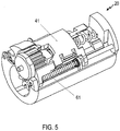
- the actuator 20 may be operative to displace the control element 41 between a first position (shown in Fig. 4 ) and a second position (shown in Fig. 5 ).
- the control element 41 When the control element 41 is in the first position, the control element 41 may cause a coupling mechanism (not shown) to be in an engaged state in which the rotary knob 11 or other manually operable actuation element of the lock is mechanically coupled, via the coupling mechanism, to a locking element (such as a latch or locking bolt).
- a locking element such as a latch or locking bolt
- the coupling mechanism may be disengaged, such that a manual operation of the rotary knob 11 or other manually operable actuation element is not transmitted to the locking element.
- control element 41 may engage a pin (which may be provided on the control element 41 or which may be coupled to the control element 41) with a mating recess for engaging the coupling mechanism, and may disengage the pin from the mating recess for disengaging the coupling mechanism.
- a pin which may be provided on the control element 41 or which may be coupled to the control element 41
- the actuator 20 may comprise a bias mechanism that biases the control element 41 into the second position. More generally, the actuator 20 may comprise a bias mechanism that biases the control element 41 into a safe position, i.e., a position in which the rotary knob 11 or other manually operable actuation element is decoupled from the locking element of the lock or in which the lock is otherwise maintained in a safe (typically locked) position.
- a safe position i.e., a position in which the rotary knob 11 or other manually operable actuation element is decoupled from the locking element of the lock or in which the lock is otherwise maintained in a safe (typically locked) position.
- the bias mechanism may comprise a bias spring 61 or other resilient element.
- the bias spring 61 or other resilient element may have a first end abutting on a shoulder 62 of the control element 41 and an opposite second end that abuts on a shoulder 63 that is fixed relative to the housing or frame of the actuator 20.
- a shoulder 63 may be formed so as to be integral with or fixedly attached to the guide rail 51.
- the bias spring 61 may be arranged such that the guide rail 51 extends through the bias spring 61 to prevent a buckling deformation or other kinking of the bias spring 61.
- the bias spring 61 Various effects are attained by the bias spring 61. For illustration, if a small mismatch between the first and second moments of inertia causes a small remnant rotation of the coil spring 34 in response to fraudulent manipulation, the bias spring 61 will ensure that the control element 41 is always displaced towards a position in which the lock remains safe. For illustration, the bias spring 61 can ensure that the control element 41 is always displaced towards a position in which a coupling mechanism between the rotary knob 11 or other manually operable actuation element and the locking element of the lock is disengaged.
- operation of the actuator 20 may be controlled by a control circuit (not shown).
- the control circuit may perform an authentication of an access element.
- the access element may be a transponder, portable phone, portable computing device, or other access element.
- the control circuit may activate the electric motor to mechanically couple the rotary knob 11 or other manually operable actuation element and the locking element of the lock, for example.
- a weight 35 may be attached to a toothed portion of the driven wheel 33.
- a mass and/or radial mass distribution of the weight 35 may be selected such that the first moment of inertia of the drive sub-unit, I 1 , is matched to the second moment of inertia of the driven sub-unit, I 2 , such that
- the actuator according to an embodiment does not need to be housed in a sleeve of a rotary door knob, but may also be arranged at other locations, e.g., in a lock cylinder or in a door fitting.
Landscapes
- Physics & Mathematics (AREA)
- Electromagnetism (AREA)
- Lock And Its Accessories (AREA)
Priority Applications (1)
| Application Number | Priority Date | Filing Date | Title |
|---|---|---|---|
| EP18200061.2A EP3636861B1 (de) | 2018-10-12 | 2018-10-12 | Stellglied für ein elektroschloss und verfahren zur betätigung eines elektroschlosses |
Applications Claiming Priority (1)
| Application Number | Priority Date | Filing Date | Title |
|---|---|---|---|
| EP18200061.2A EP3636861B1 (de) | 2018-10-12 | 2018-10-12 | Stellglied für ein elektroschloss und verfahren zur betätigung eines elektroschlosses |
Publications (2)
| Publication Number | Publication Date |
|---|---|
| EP3636861A1 true EP3636861A1 (de) | 2020-04-15 |
| EP3636861B1 EP3636861B1 (de) | 2021-08-04 |
Family
ID=63840671
Family Applications (1)
| Application Number | Title | Priority Date | Filing Date |
|---|---|---|---|
| EP18200061.2A Active EP3636861B1 (de) | 2018-10-12 | 2018-10-12 | Stellglied für ein elektroschloss und verfahren zur betätigung eines elektroschlosses |
Country Status (1)
| Country | Link |
|---|---|
| EP (1) | EP3636861B1 (de) |
Citations (7)
| Publication number | Priority date | Publication date | Assignee | Title |
|---|---|---|---|---|
| US3439554A (en) * | 1967-05-25 | 1969-04-22 | Air Reduction | Stabilization of servosystem against backlash |
| DE102004046778B4 (de) | 2004-09-24 | 2007-03-22 | Mehmet Sancak | Schließzylinder mit erhöhter Eingriffssicherheit |
| EP1803875A2 (de) * | 2005-09-30 | 2007-07-04 | Birkegården Danmark A/S | Verriegelungsanordnung für eine Tür |
| WO2011022855A1 (de) * | 2009-08-31 | 2011-03-03 | Kaba Ag | Schliesseinrichtung |
| EP2927396A1 (de) * | 2014-04-03 | 2015-10-07 | DOM Sicherheitstechnik GmbH & Co. KG | Kupplungsanordnung für Schließzylinder mit Lauffeder |
| EP2963212A1 (de) | 2014-07-01 | 2016-01-06 | Optilox B.V. | Elektromechanischer blockierungsaktuator und zugangssteuerungsvorrichtung |
| DE102015112859B3 (de) * | 2015-08-05 | 2016-11-03 | Uhlmann & Zacher Gmbh | Türdrücker und Antriebsträger |
-
2018
- 2018-10-12 EP EP18200061.2A patent/EP3636861B1/de active Active
Patent Citations (7)
| Publication number | Priority date | Publication date | Assignee | Title |
|---|---|---|---|---|
| US3439554A (en) * | 1967-05-25 | 1969-04-22 | Air Reduction | Stabilization of servosystem against backlash |
| DE102004046778B4 (de) | 2004-09-24 | 2007-03-22 | Mehmet Sancak | Schließzylinder mit erhöhter Eingriffssicherheit |
| EP1803875A2 (de) * | 2005-09-30 | 2007-07-04 | Birkegården Danmark A/S | Verriegelungsanordnung für eine Tür |
| WO2011022855A1 (de) * | 2009-08-31 | 2011-03-03 | Kaba Ag | Schliesseinrichtung |
| EP2927396A1 (de) * | 2014-04-03 | 2015-10-07 | DOM Sicherheitstechnik GmbH & Co. KG | Kupplungsanordnung für Schließzylinder mit Lauffeder |
| EP2963212A1 (de) | 2014-07-01 | 2016-01-06 | Optilox B.V. | Elektromechanischer blockierungsaktuator und zugangssteuerungsvorrichtung |
| DE102015112859B3 (de) * | 2015-08-05 | 2016-11-03 | Uhlmann & Zacher Gmbh | Türdrücker und Antriebsträger |
Non-Patent Citations (1)
| Title |
|---|
| KEITH KNIGHT: "Understanding Inertia and Reflected Inertia The Important Role Inertia Plays in Motion Control", 10 February 2015 (2015-02-10), XP055567983, Retrieved from the Internet <URL:https://www.automateshow.com/filesDownload.cfm?dl=Knight-UnderstandingInertiaandReflectedInertia.pdf> [retrieved on 20190312] * |
Also Published As
| Publication number | Publication date |
|---|---|
| EP3636861B1 (de) | 2021-08-04 |
Similar Documents
| Publication | Publication Date | Title |
|---|---|---|
| US7464627B2 (en) | Passive entry actuator | |
| US4315649A (en) | Securing device for doors or the like in vehicles | |
| EP2161398B1 (de) | Fahrzeugschloss mit sekundärem Eingriff zwischen Nocke und Hilfssperrklinke | |
| EP2310601B1 (de) | Fahrzeugschloss mit dobbelter sperrklinke | |
| EP1738980B1 (de) | Schliesssystem | |
| EP1253268A2 (de) | Schliessvorrichtung | |
| US6526790B2 (en) | Closing device | |
| US7219935B2 (en) | Latch apparatus and method | |
| EP3620599A1 (de) | Kupplungsvorrichtung für fahrzeugtürgriff | |
| CN110159084B (zh) | 电子锁及其离合机构 | |
| EP2372052B1 (de) | Schließeinrichtung umfassend eine Vorrichtung zur Zutrittskontrolle mit elektromechanischem Wandler | |
| EP2746497A2 (de) | Verriegelungsanordnung | |
| EP2163715B1 (de) | Motorbetriebene Sperrvorrichtung mit drehbarem Schlossfalle | |
| EP3927919B1 (de) | Verfahren zum entriegeln eines schlosses | |
| EP3636861B1 (de) | Stellglied für ein elektroschloss und verfahren zur betätigung eines elektroschlosses | |
| US8308203B1 (en) | Rotary mechanical latch | |
| DE102007040356A1 (de) | Koppeleinheit für elektronische Schließ-Systeme mit Umlenkelement | |
| JP6074191B2 (ja) | ドア用錠装置 | |
| EP1149967B1 (de) | Verriegelungsvorrichtung | |
| GB2457680A (en) | A latch arrangement for an automotive door | |
| JP2020176433A (ja) | 施錠装置 | |
| US20230272852A1 (en) | Parking lock device and vehicle | |
| EP4273355A1 (de) | Kupplungsaktuator für ein türschloss | |
| JP6646318B1 (ja) | 鍵機構 | |
| CN111962981A (zh) | 一种锁的联动结构以及锁 |
Legal Events
| Date | Code | Title | Description |
|---|---|---|---|
| PUAI | Public reference made under article 153(3) epc to a published international application that has entered the european phase |
Free format text: ORIGINAL CODE: 0009012 |
|
| STAA | Information on the status of an ep patent application or granted ep patent |
Free format text: STATUS: THE APPLICATION HAS BEEN PUBLISHED |
|
| AK | Designated contracting states |
Kind code of ref document: A1 Designated state(s): AL AT BE BG CH CY CZ DE DK EE ES FI FR GB GR HR HU IE IS IT LI LT LU LV MC MK MT NL NO PL PT RO RS SE SI SK SM TR |
|
| AX | Request for extension of the european patent |
Extension state: BA ME |
|
| STAA | Information on the status of an ep patent application or granted ep patent |
Free format text: STATUS: REQUEST FOR EXAMINATION WAS MADE |
|
| 17P | Request for examination filed |
Effective date: 20201012 |
|
| RBV | Designated contracting states (corrected) |
Designated state(s): AL AT BE BG CH CY CZ DE DK EE ES FI FR GB GR HR HU IE IS IT LI LT LU LV MC MK MT NL NO PL PT RO RS SE SI SK SM TR |
|
| GRAP | Despatch of communication of intention to grant a patent |
Free format text: ORIGINAL CODE: EPIDOSNIGR1 |
|
| STAA | Information on the status of an ep patent application or granted ep patent |
Free format text: STATUS: GRANT OF PATENT IS INTENDED |
|
| INTG | Intention to grant announced |
Effective date: 20210223 |
|
| GRAS | Grant fee paid |
Free format text: ORIGINAL CODE: EPIDOSNIGR3 |
|
| GRAA | (expected) grant |
Free format text: ORIGINAL CODE: 0009210 |
|
| STAA | Information on the status of an ep patent application or granted ep patent |
Free format text: STATUS: THE PATENT HAS BEEN GRANTED |
|
| AK | Designated contracting states |
Kind code of ref document: B1 Designated state(s): AL AT BE BG CH CY CZ DE DK EE ES FI FR GB GR HR HU IE IS IT LI LT LU LV MC MK MT NL NO PL PT RO RS SE SI SK SM TR |
|
| REG | Reference to a national code |
Ref country code: GB Ref legal event code: FG4D |
|
| REG | Reference to a national code |
Ref country code: AT Ref legal event code: REF Ref document number: 1417145 Country of ref document: AT Kind code of ref document: T Effective date: 20210815 |
|
| REG | Reference to a national code |
Ref country code: CH Ref legal event code: EP |
|
| REG | Reference to a national code |
Ref country code: DE Ref legal event code: R096 Ref document number: 602018021119 Country of ref document: DE |
|
| REG | Reference to a national code |
Ref country code: IE Ref legal event code: FG4D |
|
| REG | Reference to a national code |
Ref country code: SE Ref legal event code: TRGR |
|
| REG | Reference to a national code |
Ref country code: LT Ref legal event code: MG9D |
|
| REG | Reference to a national code |
Ref country code: NL Ref legal event code: MP Effective date: 20210804 |
|
| PG25 | Lapsed in a contracting state [announced via postgrant information from national office to epo] |
Ref country code: RS Free format text: LAPSE BECAUSE OF FAILURE TO SUBMIT A TRANSLATION OF THE DESCRIPTION OR TO PAY THE FEE WITHIN THE PRESCRIBED TIME-LIMIT Effective date: 20210804 Ref country code: HR Free format text: LAPSE BECAUSE OF FAILURE TO SUBMIT A TRANSLATION OF THE DESCRIPTION OR TO PAY THE FEE WITHIN THE PRESCRIBED TIME-LIMIT Effective date: 20210804 Ref country code: ES Free format text: LAPSE BECAUSE OF FAILURE TO SUBMIT A TRANSLATION OF THE DESCRIPTION OR TO PAY THE FEE WITHIN THE PRESCRIBED TIME-LIMIT Effective date: 20210804 Ref country code: FI Free format text: LAPSE BECAUSE OF FAILURE TO SUBMIT A TRANSLATION OF THE DESCRIPTION OR TO PAY THE FEE WITHIN THE PRESCRIBED TIME-LIMIT Effective date: 20210804 Ref country code: BG Free format text: LAPSE BECAUSE OF FAILURE TO SUBMIT A TRANSLATION OF THE DESCRIPTION OR TO PAY THE FEE WITHIN THE PRESCRIBED TIME-LIMIT Effective date: 20211104 Ref country code: LT Free format text: LAPSE BECAUSE OF FAILURE TO SUBMIT A TRANSLATION OF THE DESCRIPTION OR TO PAY THE FEE WITHIN THE PRESCRIBED TIME-LIMIT Effective date: 20210804 Ref country code: PT Free format text: LAPSE BECAUSE OF FAILURE TO SUBMIT A TRANSLATION OF THE DESCRIPTION OR TO PAY THE FEE WITHIN THE PRESCRIBED TIME-LIMIT Effective date: 20211206 Ref country code: NO Free format text: LAPSE BECAUSE OF FAILURE TO SUBMIT A TRANSLATION OF THE DESCRIPTION OR TO PAY THE FEE WITHIN THE PRESCRIBED TIME-LIMIT Effective date: 20211104 |
|
| PG25 | Lapsed in a contracting state [announced via postgrant information from national office to epo] |
Ref country code: PL Free format text: LAPSE BECAUSE OF FAILURE TO SUBMIT A TRANSLATION OF THE DESCRIPTION OR TO PAY THE FEE WITHIN THE PRESCRIBED TIME-LIMIT Effective date: 20210804 Ref country code: LV Free format text: LAPSE BECAUSE OF FAILURE TO SUBMIT A TRANSLATION OF THE DESCRIPTION OR TO PAY THE FEE WITHIN THE PRESCRIBED TIME-LIMIT Effective date: 20210804 Ref country code: GR Free format text: LAPSE BECAUSE OF FAILURE TO SUBMIT A TRANSLATION OF THE DESCRIPTION OR TO PAY THE FEE WITHIN THE PRESCRIBED TIME-LIMIT Effective date: 20211105 |
|
| REG | Reference to a national code |
Ref country code: AT Ref legal event code: UEP Ref document number: 1417145 Country of ref document: AT Kind code of ref document: T Effective date: 20210804 |
|
| PG25 | Lapsed in a contracting state [announced via postgrant information from national office to epo] |
Ref country code: NL Free format text: LAPSE BECAUSE OF FAILURE TO SUBMIT A TRANSLATION OF THE DESCRIPTION OR TO PAY THE FEE WITHIN THE PRESCRIBED TIME-LIMIT Effective date: 20210804 |
|
| PG25 | Lapsed in a contracting state [announced via postgrant information from national office to epo] |
Ref country code: DK Free format text: LAPSE BECAUSE OF FAILURE TO SUBMIT A TRANSLATION OF THE DESCRIPTION OR TO PAY THE FEE WITHIN THE PRESCRIBED TIME-LIMIT Effective date: 20210804 |
|
| REG | Reference to a national code |
Ref country code: DE Ref legal event code: R097 Ref document number: 602018021119 Country of ref document: DE |
|
| PG25 | Lapsed in a contracting state [announced via postgrant information from national office to epo] |
Ref country code: SM Free format text: LAPSE BECAUSE OF FAILURE TO SUBMIT A TRANSLATION OF THE DESCRIPTION OR TO PAY THE FEE WITHIN THE PRESCRIBED TIME-LIMIT Effective date: 20210804 Ref country code: SK Free format text: LAPSE BECAUSE OF FAILURE TO SUBMIT A TRANSLATION OF THE DESCRIPTION OR TO PAY THE FEE WITHIN THE PRESCRIBED TIME-LIMIT Effective date: 20210804 Ref country code: RO Free format text: LAPSE BECAUSE OF FAILURE TO SUBMIT A TRANSLATION OF THE DESCRIPTION OR TO PAY THE FEE WITHIN THE PRESCRIBED TIME-LIMIT Effective date: 20210804 Ref country code: EE Free format text: LAPSE BECAUSE OF FAILURE TO SUBMIT A TRANSLATION OF THE DESCRIPTION OR TO PAY THE FEE WITHIN THE PRESCRIBED TIME-LIMIT Effective date: 20210804 Ref country code: CZ Free format text: LAPSE BECAUSE OF FAILURE TO SUBMIT A TRANSLATION OF THE DESCRIPTION OR TO PAY THE FEE WITHIN THE PRESCRIBED TIME-LIMIT Effective date: 20210804 Ref country code: AL Free format text: LAPSE BECAUSE OF FAILURE TO SUBMIT A TRANSLATION OF THE DESCRIPTION OR TO PAY THE FEE WITHIN THE PRESCRIBED TIME-LIMIT Effective date: 20210804 |
|
| PLBE | No opposition filed within time limit |
Free format text: ORIGINAL CODE: 0009261 |
|
| STAA | Information on the status of an ep patent application or granted ep patent |
Free format text: STATUS: NO OPPOSITION FILED WITHIN TIME LIMIT |
|
| REG | Reference to a national code |
Ref country code: BE Ref legal event code: MM Effective date: 20211031 |
|
| PG25 | Lapsed in a contracting state [announced via postgrant information from national office to epo] |
Ref country code: MC Free format text: LAPSE BECAUSE OF FAILURE TO SUBMIT A TRANSLATION OF THE DESCRIPTION OR TO PAY THE FEE WITHIN THE PRESCRIBED TIME-LIMIT Effective date: 20210804 |
|
| 26N | No opposition filed |
Effective date: 20220506 |
|
| PG25 | Lapsed in a contracting state [announced via postgrant information from national office to epo] |
Ref country code: LU Free format text: LAPSE BECAUSE OF NON-PAYMENT OF DUE FEES Effective date: 20211012 Ref country code: BE Free format text: LAPSE BECAUSE OF NON-PAYMENT OF DUE FEES Effective date: 20211031 |
|
| PG25 | Lapsed in a contracting state [announced via postgrant information from national office to epo] |
Ref country code: SI Free format text: LAPSE BECAUSE OF FAILURE TO SUBMIT A TRANSLATION OF THE DESCRIPTION OR TO PAY THE FEE WITHIN THE PRESCRIBED TIME-LIMIT Effective date: 20210804 |
|
| PG25 | Lapsed in a contracting state [announced via postgrant information from national office to epo] |
Ref country code: IE Free format text: LAPSE BECAUSE OF NON-PAYMENT OF DUE FEES Effective date: 20211012 |
|
| P01 | Opt-out of the competence of the unified patent court (upc) registered |
Effective date: 20230424 |
|
| PG25 | Lapsed in a contracting state [announced via postgrant information from national office to epo] |
Ref country code: CY Free format text: LAPSE BECAUSE OF FAILURE TO SUBMIT A TRANSLATION OF THE DESCRIPTION OR TO PAY THE FEE WITHIN THE PRESCRIBED TIME-LIMIT Effective date: 20210804 |
|
| PG25 | Lapsed in a contracting state [announced via postgrant information from national office to epo] |
Ref country code: HU Free format text: LAPSE BECAUSE OF FAILURE TO SUBMIT A TRANSLATION OF THE DESCRIPTION OR TO PAY THE FEE WITHIN THE PRESCRIBED TIME-LIMIT; INVALID AB INITIO Effective date: 20181012 |
|
| PGFP | Annual fee paid to national office [announced via postgrant information from national office to epo] |
Ref country code: GB Payment date: 20231025 Year of fee payment: 6 |
|
| PGFP | Annual fee paid to national office [announced via postgrant information from national office to epo] |
Ref country code: SE Payment date: 20231012 Year of fee payment: 6 Ref country code: IT Payment date: 20231006 Year of fee payment: 6 Ref country code: FR Payment date: 20231009 Year of fee payment: 6 Ref country code: DE Payment date: 20231027 Year of fee payment: 6 Ref country code: CH Payment date: 20231102 Year of fee payment: 6 Ref country code: AT Payment date: 20231005 Year of fee payment: 6 |
|
| PG25 | Lapsed in a contracting state [announced via postgrant information from national office to epo] |
Ref country code: MK Free format text: LAPSE BECAUSE OF FAILURE TO SUBMIT A TRANSLATION OF THE DESCRIPTION OR TO PAY THE FEE WITHIN THE PRESCRIBED TIME-LIMIT Effective date: 20210804 |