EP3636586A1 - Automated guided vehicle - Google Patents
Automated guided vehicle Download PDFInfo
- Publication number
- EP3636586A1 EP3636586A1 EP17912761.8A EP17912761A EP3636586A1 EP 3636586 A1 EP3636586 A1 EP 3636586A1 EP 17912761 A EP17912761 A EP 17912761A EP 3636586 A1 EP3636586 A1 EP 3636586A1
- Authority
- EP
- European Patent Office
- Prior art keywords
- head
- contact
- vehicle body
- electric actuator
- control unit
- Prior art date
- Legal status (The legal status is an assumption and is not a legal conclusion. Google has not performed a legal analysis and makes no representation as to the accuracy of the status listed.)
- Granted
Links
Images



Classifications
-
- B—PERFORMING OPERATIONS; TRANSPORTING
- B60—VEHICLES IN GENERAL
- B60G—VEHICLE SUSPENSION ARRANGEMENTS
- B60G17/00—Resilient suspensions having means for adjusting the spring or vibration-damper characteristics, for regulating the distance between a supporting surface and a sprung part of vehicle or for locking suspension during use to meet varying vehicular or surface conditions, e.g. due to speed or load
- B60G17/015—Resilient suspensions having means for adjusting the spring or vibration-damper characteristics, for regulating the distance between a supporting surface and a sprung part of vehicle or for locking suspension during use to meet varying vehicular or surface conditions, e.g. due to speed or load the regulating means comprising electric or electronic elements
- B60G17/016—Resilient suspensions having means for adjusting the spring or vibration-damper characteristics, for regulating the distance between a supporting surface and a sprung part of vehicle or for locking suspension during use to meet varying vehicular or surface conditions, e.g. due to speed or load the regulating means comprising electric or electronic elements characterised by their responsiveness, when the vehicle is travelling, to specific motion, a specific condition, or driver input
-
- B—PERFORMING OPERATIONS; TRANSPORTING
- B61—RAILWAYS
- B61B—RAILWAY SYSTEMS; EQUIPMENT THEREFOR NOT OTHERWISE PROVIDED FOR
- B61B13/00—Other railway systems
-
- B—PERFORMING OPERATIONS; TRANSPORTING
- B62—LAND VEHICLES FOR TRAVELLING OTHERWISE THAN ON RAILS
- B62D—MOTOR VEHICLES; TRAILERS
- B62D49/00—Tractors
- B62D49/08—Tractors having means for preventing overturning or tipping
-
- B—PERFORMING OPERATIONS; TRANSPORTING
- B66—HOISTING; LIFTING; HAULING
- B66F—HOISTING, LIFTING, HAULING OR PUSHING, NOT OTHERWISE PROVIDED FOR, e.g. DEVICES WHICH APPLY A LIFTING OR PUSHING FORCE DIRECTLY TO THE SURFACE OF A LOAD
- B66F9/00—Devices for lifting or lowering bulky or heavy goods for loading or unloading purposes
- B66F9/06—Devices for lifting or lowering bulky or heavy goods for loading or unloading purposes movable, with their loads, on wheels or the like, e.g. fork-lift trucks
- B66F9/075—Constructional features or details
- B66F9/20—Means for actuating or controlling masts, platforms, or forks
- B66F9/24—Electrical devices or systems
Definitions
- an outrigger is used in the fall prevention device of the automated guided vehicle.
- the automated guided vehicle equipped with the outrigger for example, the one described in patent literature 1 or the one shown in FIG. 5 is known.
- the present invention is accomplished based on the above condition and provides an automated guided vehicle which can be used in a clean environment and in which increases in the scale of a vehicle body can be suppressed.
- the automated guided vehicle can be a configuration in which the first electric actuator includes a first motor rotating under the control of the control unit, and a first electric jack having the first head that moves vertically corresponding to the rotation of the first motor, the second electric actuator includes a second motor rotating under the control of the control unit, and a second electric jack having the second head that moves vertically corresponding to the rotation of the second motor, and the first motor and the second motor are disposed opposite to each other inside the vehicle body.
- the first drive unit 4 has the first running wheel 4a, a motor for driving the first running wheel 4a, a speed reduction mechanism and the like.
- the second drive unit 5 has the second running wheel 5a, a motor for driving the second running wheel 5a, a speed reduction mechanism and the like.
- a first upper limit sensor 17a and a first lower limit sensor 17b are arranged.
- the first upper limit sensor 17a indirectly detects that the movement of the first head 11a reaches the upper limit by detecting an upper end of the first dog 11d.
- the first lower limit sensor 17b indirectly detects that the movement of the first head 11a reaches the lower limit by detecting the upper end of the first dog 11d.
- Detection signals of the first upper limit sensor 17a and the first lower limit sensor 17b are output to the control unit 13.
- the control unit 13 stops the rotation of the first motor 11c when the detection signal of the first upper limit sensor 17a or the first lower limit sensor 17b is input.
- the control unit 13 consists of a control IC for example and is arranged inside the vehicle body 2.
- a case in which the cargo handling operation is performed on the left side of the vehicle body 2 (the side of the first running wheel 4a and the third running wheel 6a) is used as an example to describe the control of the control unit 13.
- the fall prevention device is configured by the first electric actuator 11, the second electric actuator 12, and the control unit 13, and no hydraulic actuator (for example, a hydraulic outrigger) is used. Accordingly, the automated guided vehicle 1 of the embodiment is suitable for use in a clean environment.
- the fork of the present invention may be a fork other than the slide fork 3 as long as the fork is configured to perform the cargo handling operation outside the vehicle body 2.
Landscapes
- Engineering & Computer Science (AREA)
- Transportation (AREA)
- Mechanical Engineering (AREA)
- Chemical & Material Sciences (AREA)
- Combustion & Propulsion (AREA)
- Structural Engineering (AREA)
- Civil Engineering (AREA)
- Life Sciences & Earth Sciences (AREA)
- Geology (AREA)
- Platform Screen Doors And Railroad Systems (AREA)
- Forklifts And Lifting Vehicles (AREA)
- Warehouses Or Storage Devices (AREA)
Abstract
Description
- The present invention relates to an automated guided vehicle equipped with a fall prevention device.
- Generally, an outrigger is used in the fall prevention device of the automated guided vehicle. As the automated guided vehicle equipped with the outrigger, for example, the one described in
patent literature 1 or the one shown inFIG. 5 is known. - In an automated guided vehicle 1' shown in
FIG. 5 , runningwheels 4a-7a are arranged in four corners of avehicle body 2, andhydraulic outriggers 20 are arranged outside the runningwheels 4a-7a. The automated guided vehicle 1' can prevent thevehicle body 2 from sloping and falling over due to the weight of a transferred workpiece by bringing theoutrigger 20 into contact with a floor during a cargo handling operation. - Patent literature 1: Japanese Laid-Open No.
5-310103 - Meanwhile, when the automated guided vehicle 1' is used in a clean environment such as a clean room, arrangement of an electric outrigger in place of the
hydraulic outrigger 20 is required. The electric outrigger is increased in the scale compared with thehydraulic outrigger 20, and thus there is a problem that thevehicle body 2 is increased in the scale if the electric outrigger is arranged in the automated guided vehicle 1'. - The present invention is accomplished based on the above condition and provides an automated guided vehicle which can be used in a clean environment and in which increases in the scale of a vehicle body can be suppressed.
- To solve the above problem, the automated guided vehicle of the present invention includes: a vehicle body; a fork, performing a cargo handling operation outside the vehicle body; a first drive unit, disposed on one side of the vehicle body and having a first running wheel; a second drive unit, disposed on the other side of the vehicle body and having a second running wheel; a drive linkage, linking the first drive unit and the second drive unit so that the first drive unit and the second drive unit oscillate vertically opposite to each other; and a fall prevention device, preventing the vehicle body from falling over; the fall prevention device includes: a control unit; a first electric actuator, having a first head that moves vertically under the control of the control unit and being attached to a frame of the vehicle body above the first drive unit; and a second electric actuator, having a second head that moves vertically under the control of the control unit and being attached to the frame above the second drive unit; and the first electric actuator prevents the vehicle body from falling over toward the one side by moving the first head downward to bring the first head into contact with the drive linkage, and the second electric actuator prevents the vehicle body from falling over toward the other side by moving the second head downward to bring the second head into contact with the drive linkage.
- In the automated guided vehicle, preferably, the fork is a slide fork which performs the cargo handling operation on the one side and the other side; in a case of the cargo handling operation on the one side, the control unit brings the first head into contact with the drive linkage without bringing the second head into contact with the drive linkage; in a case of the cargo handling operation on the other side, the control unit brings the second head into contact with the drive linkage without bringing the first head into contact with the drive linkage.
- The automated guided vehicle can be a configuration in which the first electric actuator and the second electric actuator are attached to an upper surface of the frame, the frame has a first opening portion which is located above the first drive unit and through which the first head enters, and a second opening portion which is located above the second drive unit and through which the second head enters, and the drive linkage has a first head contact surface in contact with the first head in the first opening portion and a second head contact surface in contact with the second head in the second opening portion.
- In the automated guided vehicle, a first sensor which detects the contact of the first head with the drive linkage, and a second sensor which detects the contact of the second head with the drive linkage may be arranged.
- The automated guided vehicle can be a configuration in which the first electric actuator includes a first motor rotating under the control of the control unit, and a first electric jack having the first head that moves vertically corresponding to the rotation of the first motor, the second electric actuator includes a second motor rotating under the control of the control unit, and a second electric jack having the second head that moves vertically corresponding to the rotation of the second motor, and the first motor and the second motor are disposed opposite to each other inside the vehicle body.
- The automated guided vehicle can be a configuration in which the vehicle body includes, above the frame, a storage room for storing the fork along with a transferred workpiece, the storage room includes a shutter which is opened and closed under the control of the control unit, and the control unit opens the shutter after bringing the first head or the second head into contact with the drive linkage, and closes the shutter after the end of the cargo handling operation to release the contact with the drive linkage.
- According to the present invention, an automated guided vehicle can be provided which can be used in a clean environment and in which increases in the scale of a vehicle body can be suppressed.
-
-
FIG. 1 is a diagram showing an automated guided vehicle of the present invention, wherein (A) is a plan view, (B) is a left side view, and (C) is a rear view. -
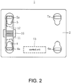
FIG. 2 is a bottom view of the automated guided vehicle of the present invention. -
FIG. 3 is diagram showing a fall prevention device of the present invention and a peripheral configuration of the fall prevention device. -
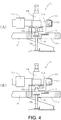
FIG. 4 is a diagram showing the fall prevention device of the present invention, wherein (A) is a diagram during a cargo handling operation, and (B) is a diagram after the end of the cargo handling operation. -
FIG. 5 is a bottom view of a conventional automated guided vehicle. - In the following, embodiments of an automated guided vehicle of the present invention is described with reference to the attached drawings. Besides, front-rear, left-right, and up-down directions are considered taking a vehicle body of the automated guided vehicle as reference unless otherwise noted.
- In
FIG. 1(A) - (C) , an automated guidedvehicle 1 of one embodiment of the present invention is shown. The automated guidedvehicle 1 is used, for example, in a clean environment such as a clean room. The automated guidedvehicle 1 includes avehicle body 2 and aslide fork 3 arranged on thevehicle body 2. - In four corners of the bottom surface side of the
vehicle body 2, a first running wheel (a left-front wheel) 4a, a second running wheel (a right-front wheel) 5a, a third running wheel (a left-rear wheel) 6a and a fourth running wheel (a right-rear wheel) 7a are arranged. In addition, thevehicle body 2 includes astorage room 8 for storing theslide fork 3 along with a transferred workpiece W. Thestorage room 8 includes ashutter 9. Theshutter 9 is configured to be opened just before a cargo handling operation and be closed after the cargo handling operation. - The
shutter 9 is arranged not only on the left side of thestorage room 8 but also on the right side (the side of the second runningwheel 5a and the fourth runningwheel 7a). When theslide fork 3 in thestorage room 8 is made to slide to the left side and the cargo handling operation is performed on the left outside of thevehicle body 2, theshutter 9 on the left is opened. On the other hand, when theslide fork 3 in thestorage room 8 is made to slide to the right side and the cargo handling operation is performed on the right outside of thevehicle body 2, theshutter 9 on the right is opened. A slide operation of theslide fork 3 and an opening and closing operation of theshutter 9 are performed under the control of acontrol unit 13 shown inFIG. 2 . Besides, theslide fork 3 can gyrate in thestorage room 8 under the control of thecontrol unit 13. - As shown in
FIG. 2 , the automated guidedvehicle 1 includes: afirst drive unit 4 including the first runningwheel 4a, asecond drive unit 5 including the second runningwheel 5a, adrive linkage 10 linking thefirst drive unit 4 and thesecond drive unit 5, and a fall prevention device (11, 12, 13) for preventing thevehicle body 2 from falling over during the cargo handling operation. - The
first drive unit 4 has the first runningwheel 4a, a motor for driving the first runningwheel 4a, a speed reduction mechanism and the like. Similarly, thesecond drive unit 5 has the second runningwheel 5a, a motor for driving the second runningwheel 5a, a speed reduction mechanism and the like. - The
drive linkage 10 is a linking mechanism which links thefirst drive unit 4 and thesecond drive unit 5 so that thefirst drive unit 4 and thesecond drive unit 5 oscillate vertically opposite to each other. According to thedrive linkage 10, for example, when thefirst drive unit 4 oscillates upward due to the sloping of a floor or the like, thesecond drive unit 5 oscillates downward and thus a posture of thevehicle body 2 is kept horizontal. - As shown in
FIG. 3 , thedrive linkage 10 includes afirst contact member 10a and asecond contact member 10b. Thefirst contact member 10a has a firsthead contact surface 10c in contact with thefirst head 11a of the fall prevention device. Thesecond contact member 10b has a secondhead contact surface 10d in contact with thesecond head 12a of the fall prevention device. - When the
first head 11a is in contact with the firsthead contact surface 10c, at least thefirst drive unit 4 is prevented from oscillating upward. In other words, thevehicle body 2 is prevented from sloping toward thefirst drive unit 4 side. When thesecond head 12a is in contact with the secondhead contact surface 10d, at least thesecond drive unit 5 is prevented from oscillating upward. In other words, thevehicle body 2 is prevented from sloping toward thesecond drive unit 5 side. - The fall prevention device of this embodiment includes a first
electric actuator 11, a secondelectric actuator 12, and thecontrol unit 13, but does not include a hydraulic actuator (for example, a hydraulic outrigger). Therefore, the fall prevention device of the embodiment has no risk of oil leakage and is suitable for use in a clean environment. - Furthermore, four devices are required when the fall prevention device is configured by an outrigger; however, the fall prevention device is configured by two devices (the first
electric actuator 11 and the second electric actuator 12) in this embodiment. Therefore, in the embodiment, decreases in the scale of the fall prevention device can be achieved. - As shown in
FIG. 2 andFIG. 3 , the firstelectric actuator 11 is attached to aframe 14 of thevehicle body 2 above thefirst drive unit 4. The firstelectric actuator 11 includes a firstelectric jack 11b having thefirst head 11a, afirst motor 11c, and afirst dog 11d. - The
first motor 11c rotates under the control of thecontrol unit 13. The firstelectric jack 11b moves thefirst head 11a vertically corresponding to the rotation of thefirst motor 11c. For example, thefirst head 11a moves downward in a case of a positive rotation of thefirst motor 11c, and thefirst head 11a moves upward in a case of a negative rotation of thefirst motor 11c. Thefirst dog 11d is attached to the firstelectric jack 11b so as to move vertically along with thefirst head 11a. - The second
electric actuator 12 is attached to theframe 14 of thevehicle body 2 above thesecond drive unit 5. The secondelectric actuator 12 includes a secondelectric jack 12b having thesecond head 12a, asecond motor 12c, and asecond dog 12d. - The
second motor 12c rotates under the control of thecontrol unit 13. The secondelectric jack 12b moves thesecond head 12a vertically corresponding to the rotation of thesecond motor 12c. For example, thesecond head 12a moves downward in a case of a positive rotation of thesecond motor 12c, and thesecond head 12a moves upward in a case of a negative rotation of thesecond motor 12c. Thesecond dog 12d is attached to the secondelectric jack 12b so as to move vertically along with thesecond head 12a. - The
frame 14 of thevehicle body 2 has afirst opening portion 14a which is located above thefirst drive unit 4 and through which thefirst head 11a enters, and asecond opening portion 14b which is located above thesecond drive unit 5 and through which thesecond head 12a enters. Inside thefirst opening portion 14a, afirst sensor 15 attached to thefirst contact member 10a of thedrive linkage 10 is disposed via a bracket. Inside thesecond opening portion 14b, asecond sensor 16 attached to thesecond contact member 10b of thedrive linkage 10 is disposed via a bracket. - The
first sensor 15 indirectly detects the contact of thefirst head 11a with the firsthead contact surface 10c by detecting a lower end of thefirst dog 11d (seeFIG. 4(A) ). A detection signal of thefirst sensor 15 is output to thecontrol unit 13. Thecontrol unit 13 stops the rotation of thefirst motor 11c when the detection signal of thefirst sensor 15 is input. Besides, thefirst sensor 15 may also directly detect the contact of thefirst head 11a with the firsthead contact surface 10c. - The
second sensor 16 indirectly detects the contact of thesecond head 12a with the secondhead contact surface 10d by detecting a lower end of thesecond dog 12d. A detection signal of thesecond sensor 16 is output to thecontrol unit 13. Thecontrol unit 13 stops the rotation of thesecond motor 12c when the detection signal of thesecond sensor 16 is input. Besides, thesecond sensor 16 may also directly detect the contact of thesecond head 12a with the secondhead contact surface 10d. - In the first
electric actuator 11, a firstupper limit sensor 17a and a firstlower limit sensor 17b are arranged. The firstupper limit sensor 17a indirectly detects that the movement of thefirst head 11a reaches the upper limit by detecting an upper end of thefirst dog 11d. The firstlower limit sensor 17b indirectly detects that the movement of thefirst head 11a reaches the lower limit by detecting the upper end of thefirst dog 11d. Detection signals of the firstupper limit sensor 17a and the firstlower limit sensor 17b are output to thecontrol unit 13. Thecontrol unit 13 stops the rotation of thefirst motor 11c when the detection signal of the firstupper limit sensor 17a or the firstlower limit sensor 17b is input. - In the second
electric actuator 12, a secondupper limit sensor 18a and a secondlower limit sensor 18b are arranged. The secondupper limit sensor 18a indirectly detects that the movement of thesecond head 12a reaches the upper limit by detecting an upper end of thesecond dog 12d. The secondlower limit sensor 18b indirectly detects that the movement of thesecond head 12a reaches the lower limit by detecting the upper end of thesecond dog 12d. Detection signals of the secondupper limit sensor 18a and the secondlower limit sensor 18b are output to thecontrol unit 13. Thecontrol unit 13 stops the rotation of thesecond motor 12c when the detection signal of the secondupper limit sensor 18a or the secondlower limit sensor 18b is input. - As shown in
FIG. 3 , in the firstelectric actuator 11, an area of thefirst motor 11c (an area on the internal side of the firstelectric jack 11b) is larger than an area of the firstupper limit sensor 17a and the firstlower limit sensor 17b (an area on the external side of the firstelectric jack 11b). Similarly, in the secondelectric actuator 12, an area of thesecond motor 12c (an area on the internal side of the secondelectric jack 12b) is larger than an area of the secondupper limit sensor 18a and the secondlower limit sensor 18b (an area on the external side of the secondelectric jack 12b). Therefore, in the embodiment, thefirst motor 11c and thesecond motor 12c are disposed opposite to each other inside thevehicle body 2, and increases in the scale of thevehicle body 2 are suppressed. - The
control unit 13 consists of a control IC for example and is arranged inside thevehicle body 2. In the following, a case in which the cargo handling operation is performed on the left side of the vehicle body 2 (the side of thefirst running wheel 4a and thethird running wheel 6a) is used as an example to describe the control of thecontrol unit 13. - When the automated guided
vehicle 1 arrives at a station to perform the cargo handling operation, thecontrol unit 13 rotates (positively rotates) thefirst motor 11c of the firstelectric actuator 11 to bring thefirst head 11a into contact with the firsthead contact surface 10c (seeFIG. 4(A) ). - At this time, the
control unit 13 does not rotate thesecond motor 12c of the secondelectric actuator 12 and maintains a state that thesecond head 12a is separated from the secondhead contact surface 10d. The reason is that it is preferable not to increase the contact surface beyond necessity in a clean environment. Besides, when the cargo handling operation is performed on the right side of thevehicle body 2, thesecond head 12a is brought into contact with the secondhead contact surface 10d in the state that thefirst head 11a is separated from the firsthead contact surface 10c. - Next, the
control unit 13 opens theshutter 9 on the left of thestorage room 8 to perform the cargo handling operation. When theshutter 9 on the left is completely opened, thecontrol unit 13 makes theslide fork 3 in thestorage room 8 slide to the left side and loads the transferred workpiece W on the slide fork 3 (for example, seeFIG. 1(A) ). At this time, thefirst head 11a is in contact with the firsthead contact surface 10c, and thus thevehicle body 2 is prevented from sloping to the left side. That is, thevehicle body 2 does not fall over to the left side even if a fall moment of the transferred workpiece W acts on thevehicle body 2. - Next, the
control unit 13 makes theslide fork 3 loaded with the transferred workpiece W slide into thevehicle body 2 and stores theslide fork 3 loaded with the transferred workpiece W into thestorage room 8. When the transferred workpiece W is stored in the storage room 8 (the cargo handling operation ends), thecontrol unit 13 closes theshutter 9. - Next, the
control unit 13 rotates (negatively rotates) thefirst motor 11c of the firstelectric actuator 11 and separates thefirst head 11a from the firsthead contact surface 10c (seeFIG. 4(B) ). When thefirst head 11a is separated from the firsthead contact surface 10c, the automated guidedvehicle 1 restarts running. - After all, in the automated guided
vehicle 1 of the embodiment, the fall prevention device is configured by the firstelectric actuator 11, the secondelectric actuator 12, and thecontrol unit 13, and no hydraulic actuator (for example, a hydraulic outrigger) is used. Accordingly, the automated guidedvehicle 1 of the embodiment is suitable for use in a clean environment. - In addition, the first
electric actuator 11 and the secondelectric actuator 12 directly fix thedrive linkage 10 instead of holding down the floor as the outrigger does, and thus there is no limit of being disposed outside thefirst drive unit 4 and thesecond drive unit 5. Accordingly, the automated guidedvehicle 1 of the embodiment can suppresses increases in the scale of thevehicle body 2. - The embodiment of the automated guided vehicle of the present invention is described above, but the present invention is not limited to the above embodiment.
- For example, the first
electric actuator 11 can be changed in configuration as long as the firstelectric actuator 11 has thefirst head 11a that moves vertically under the control of thecontrol unit 13. Similarly, the secondelectric actuator 12 can be changed in configuration as long as the secondelectric actuator 12 has thesecond head 12a that moves vertically under the control of thecontrol unit 13. - The fork of the present invention may be a fork other than the
slide fork 3 as long as the fork is configured to perform the cargo handling operation outside thevehicle body 2. -
- 1
- automated guided vehicle
- 2
- vehicle body
- 3
- slide fork
- 4
- first drive unit
- 5
- second drive unit
- 4a-7a
- first-fourth running wheels
- 8
- storage room
- 9
- shutter
- 10
- drive linkage
- 11
- first electric actuator
- 12
- second electric actuator
- 13
- control unit
- 14
- frame
- 15
- first sensor
- 16
- second sensor
- 17a
- first upper limit sensor
- 17b
- first lower limit sensor
- 18a
- second upper limit sensor
- 18b
- second lower limit sensor
Claims (6)
- An automated guided vehicle, comprising:a vehicle body;a fork, performing a cargo handling operation outside the vehicle body;a first drive unit, disposed on one side of the vehicle body and having a first running wheel;a second drive unit, disposed on the other side of the vehicle body and having a second running wheel;a drive linkage, linking the first drive unit and the second drive unit so that the first drive unit and the second drive unit oscillate vertically opposite to each other; anda fall prevention device, preventing the vehicle body from falling over;wherein the fall prevention device comprises:a control unit;a first electric actuator, having a first head that moves vertically under the control of the control unit and being attached to a frame of the vehicle body above the first drive unit; anda second electric actuator, having a second head that moves vertically under the control of the control unit and being attached to the frame above the second drive unit;wherein the first electric actuator prevents the vehicle body from falling over toward the one side by moving the first head downward to bring the first head into contact with the drive linkage, andthe second electric actuator prevents the vehicle body from falling over toward the other side by moving the second head downward to bring the second head into contact with the drive linkage.
- The automated guided vehicle according to claim 1,
wherein the fork is a slide fork which performs the cargo handling operation on the one side and the other side;
in a case of the cargo handling operation on the one side, the control unit brings the first head into contact with the drive linkage without bringing the second head into contact with the drive linkage;
in a case of the cargo handling operation on the other side, the control unit brings the second head into contact with the drive linkage without bringing the first head into contact with the drive linkage. - The automated guided vehicle according to claim 1 or 2,
wherein the first electric actuator and the second electric actuator are attached to an upper surface of the frame;
the frame has a first opening portion which is located above the first drive unit and through which the first head enters, and a second opening portion which is located above the second drive unit and through which the second head enters; and
the drive linkage has a first head contact surface in contact with the first head in the first opening portion and a second head contact surface in contact with the second head in the second opening portion. - The automated guided vehicle according to any one of claims 1 to 3, comprising:a first sensor which detects the contact of the first head with the drive linkage, anda second sensor which detects the contact of the second head with the drive linkage.
- The automated guided vehicle according to any one of claims 1 to 4, wherein the first electric actuator comprises:a first motor rotating under the control of the control unit, anda first electric jack having the first head that moves vertically corresponding to the rotation of the first motor;the second electric actuator comprises:a second motor rotating under the control of the control unit, anda second electric jack having the second head that moves vertically corresponding to the rotation of the second motor; andthe first motor and the second motor are disposed opposite to each other inside the vehicle body.
- The automated guided vehicle according to any one of claims 1 to 5, wherein the vehicle body comprises, above the frame, a storage room for storing the fork along with a transferred workpiece;
the storage room comprises a shutter which is opened and closed under the control of the control unit; and
the control unit opens the shutter after bringing the first head or the second head into contact with the drive linkage, and closes the shutter after the end of the cargo handling operation to release the contact with the drive linkage.
Applications Claiming Priority (2)
| Application Number | Priority Date | Filing Date | Title |
|---|---|---|---|
| JP2017110596A JP6435020B1 (en) | 2017-06-05 | 2017-06-05 | Automated guided vehicle |
| PCT/JP2017/030656 WO2018225279A1 (en) | 2017-06-05 | 2017-08-28 | Automated guided vehicle |
Publications (3)
| Publication Number | Publication Date |
|---|---|
| EP3636586A1 true EP3636586A1 (en) | 2020-04-15 |
| EP3636586A4 EP3636586A4 (en) | 2021-01-27 |
| EP3636586B1 EP3636586B1 (en) | 2025-08-13 |
Family
ID=64560729
Family Applications (1)
| Application Number | Title | Priority Date | Filing Date |
|---|---|---|---|
| EP17912761.8A Active EP3636586B1 (en) | 2017-06-05 | 2017-08-28 | Automated guided vehicle |
Country Status (4)
| Country | Link |
|---|---|
| EP (1) | EP3636586B1 (en) |
| JP (1) | JP6435020B1 (en) |
| CN (1) | CN110520379B (en) |
| WO (1) | WO2018225279A1 (en) |
Families Citing this family (3)
| Publication number | Priority date | Publication date | Assignee | Title |
|---|---|---|---|---|
| KR102200667B1 (en) * | 2019-05-30 | 2021-01-15 | 마구야오 | Jacking structure of link type and automated guided vehicle |
| JP7432868B2 (en) * | 2020-02-27 | 2024-02-19 | パナソニックIpマネジメント株式会社 | Moving objects, transport devices, and component mounting systems |
| US11059671B1 (en) | 2020-03-20 | 2021-07-13 | Toyota Motor Engineering & Manufacturing North America, Inc. | Cassette stopping mechanism |
Family Cites Families (15)
| Publication number | Priority date | Publication date | Assignee | Title |
|---|---|---|---|---|
| SE449988B (en) * | 1985-10-15 | 1987-06-01 | Mecanum Ab | PROCEDURE FOR POSITIONING OF VEHICLES IN THE EXACT CONDITIONS OF GEOGRAPHICAL REFERENCE MARKING |
| US5112183A (en) * | 1989-04-25 | 1992-05-12 | Howard G. Nusbaum | Side-loading fork lift vehicle |
| JP2955799B2 (en) | 1992-05-12 | 1999-10-04 | 日本輸送機株式会社 | Outrigger device for automatic guided vehicle |
| JP2939849B2 (en) * | 1993-07-13 | 1999-08-25 | 日本車輌製造株式会社 | Automatic guided vehicle |
| JPH09142780A (en) * | 1995-11-20 | 1997-06-03 | Shinko Electric Co Ltd | Vehicle anti-vibration device |
| JP3867866B2 (en) * | 1996-05-28 | 2007-01-17 | 株式会社日立プラントテクノロジー | Automated guided vehicle |
| JP3389962B2 (en) * | 1996-08-30 | 2003-03-24 | 株式会社ダイフク | Goods carrier |
| JPH11139126A (en) * | 1997-11-05 | 1999-05-25 | Murata Mach Ltd | Automated guided vehicle |
| TW522103B (en) * | 1997-11-14 | 2003-03-01 | Toyoda Automatic Loom Works | Axle tilt control apparatus for industrial vehicles |
| JPH11199197A (en) * | 1997-11-14 | 1999-07-27 | Toyota Autom Loom Works Ltd | Rear wheel axle rocking control device for forklift |
| JPH11335094A (en) * | 1998-05-27 | 1999-12-07 | Toyota Autom Loom Works Ltd | Lock mechanism |
| JP3480723B2 (en) * | 2001-03-14 | 2003-12-22 | 日野自動車株式会社 | Height lock device |
| JP4079619B2 (en) * | 2001-10-15 | 2008-04-23 | 松下電器産業株式会社 | Automated guided vehicle and traveling control method thereof |
| CN204226549U (en) * | 2014-10-09 | 2015-03-25 | 林德(中国)叉车有限公司 | Hydraulic balance wheel apparatus |
| CN205836622U (en) * | 2016-06-21 | 2016-12-28 | 沈阳霹雳科技有限公司 | A kind of goods position regulating device of transport vehicle |
-
2017
- 2017-06-05 JP JP2017110596A patent/JP6435020B1/en active Active
- 2017-08-28 EP EP17912761.8A patent/EP3636586B1/en active Active
- 2017-08-28 WO PCT/JP2017/030656 patent/WO2018225279A1/en not_active Ceased
- 2017-08-28 CN CN201780089336.1A patent/CN110520379B/en active Active
Also Published As
| Publication number | Publication date |
|---|---|
| EP3636586A4 (en) | 2021-01-27 |
| CN110520379B (en) | 2020-12-15 |
| EP3636586B1 (en) | 2025-08-13 |
| CN110520379A (en) | 2019-11-29 |
| JP6435020B1 (en) | 2018-12-05 |
| WO2018225279A1 (en) | 2018-12-13 |
| JP2018203047A (en) | 2018-12-27 |
Similar Documents
| Publication | Publication Date | Title |
|---|---|---|
| EP3636586B1 (en) | Automated guided vehicle | |
| EP3153651B1 (en) | Power door opening and closing device | |
| CN108622102A (en) | Vehicle input operation auxiliary device | |
| JP7061946B2 (en) | Work machine cabs, work machines, and automatic switchgear | |
| US10120391B2 (en) | Self-balancing enclosed motorcycle | |
| JP5089219B2 (en) | Cargo handling vehicle | |
| CN110255447B (en) | Forward type fork truck chassis and forward type fork truck | |
| CN218023836U (en) | Unmanned transport vehicle | |
| US20170008742A1 (en) | Standing platform for an industrial truck | |
| KR101400027B1 (en) | Automobile enable to easily load/unlaod object into/from trunk room and method therefor | |
| CN110799441B (en) | Door device of elevator and connecting rod of elevator door | |
| KR101228869B1 (en) | Elevator for hood in vehicles and control method thereof | |
| CN109484549A (en) | Balance car is liftoff braking method and balance car | |
| KR101537003B1 (en) | Opening and closing apparatus of cargo gate | |
| EP2428619B1 (en) | Working vehicle | |
| JP2019127205A (en) | Lid opening and closing device of work vehicle | |
| JPH09309309A (en) | Control device of industrial vehicle | |
| KR20170001090U (en) | Electric Cart | |
| KR20250152881A (en) | Emergency wheel and logistics robot equipped with this | |
| JP4839089B2 (en) | Container handling vehicle | |
| JP2008056435A (en) | Elevator doorway safety device | |
| JP2020163483A (en) | robot | |
| JP2008302866A (en) | Canopy opening and closing device | |
| JP6004457B1 (en) | FORKLIFT DRIVE DEVICE AND FORKLIFT | |
| JPH0582236U (en) | Glen tank safety device for combine harvesters |
Legal Events
| Date | Code | Title | Description |
|---|---|---|---|
| STAA | Information on the status of an ep patent application or granted ep patent |
Free format text: STATUS: THE INTERNATIONAL PUBLICATION HAS BEEN MADE |
|
| PUAI | Public reference made under article 153(3) epc to a published international application that has entered the european phase |
Free format text: ORIGINAL CODE: 0009012 |
|
| STAA | Information on the status of an ep patent application or granted ep patent |
Free format text: STATUS: REQUEST FOR EXAMINATION WAS MADE |
|
| 17P | Request for examination filed |
Effective date: 20191028 |
|
| AK | Designated contracting states |
Kind code of ref document: A1 Designated state(s): AL AT BE BG CH CY CZ DE DK EE ES FI FR GB GR HR HU IE IS IT LI LT LU LV MC MK MT NL NO PL PT RO RS SE SI SK SM TR |
|
| AX | Request for extension of the european patent |
Extension state: BA ME |
|
| DAV | Request for validation of the european patent (deleted) | ||
| DAX | Request for extension of the european patent (deleted) | ||
| A4 | Supplementary search report drawn up and despatched |
Effective date: 20210111 |
|
| RIC1 | Information provided on ipc code assigned before grant |
Ipc: B60G 17/016 20060101ALI20201218BHEP Ipc: G05D 1/02 20200101ALI20201218BHEP Ipc: B61B 13/00 20060101ALI20201218BHEP Ipc: B66F 9/24 20060101AFI20201218BHEP Ipc: B62D 49/08 20060101ALI20201218BHEP |
|
| STAA | Information on the status of an ep patent application or granted ep patent |
Free format text: STATUS: EXAMINATION IS IN PROGRESS |
|
| 17Q | First examination report despatched |
Effective date: 20221212 |
|
| GRAP | Despatch of communication of intention to grant a patent |
Free format text: ORIGINAL CODE: EPIDOSNIGR1 |
|
| STAA | Information on the status of an ep patent application or granted ep patent |
Free format text: STATUS: GRANT OF PATENT IS INTENDED |
|
| RIC1 | Information provided on ipc code assigned before grant |
Ipc: B62D 49/08 20060101ALI20250402BHEP Ipc: B61B 13/00 20060101ALI20250402BHEP Ipc: B60G 17/016 20060101ALI20250402BHEP Ipc: B66F 9/24 20060101AFI20250402BHEP |
|
| INTG | Intention to grant announced |
Effective date: 20250424 |
|
| P01 | Opt-out of the competence of the unified patent court (upc) registered |
Free format text: CASE NUMBER: APP_22963/2025 Effective date: 20250514 |
|
| GRAS | Grant fee paid |
Free format text: ORIGINAL CODE: EPIDOSNIGR3 |
|
| GRAA | (expected) grant |
Free format text: ORIGINAL CODE: 0009210 |
|
| STAA | Information on the status of an ep patent application or granted ep patent |
Free format text: STATUS: THE PATENT HAS BEEN GRANTED |
|
| AK | Designated contracting states |
Kind code of ref document: B1 Designated state(s): AL AT BE BG CH CY CZ DE DK EE ES FI FR GB GR HR HU IE IS IT LI LT LU LV MC MK MT NL NO PL PT RO RS SE SI SK SM TR |
|
| REG | Reference to a national code |
Ref country code: GB Ref legal event code: FG4D |
|
| REG | Reference to a national code |
Ref country code: CH Ref legal event code: EP |
|
| REG | Reference to a national code |
Ref country code: DE Ref legal event code: R096 Ref document number: 602017091246 Country of ref document: DE |
|
| REG | Reference to a national code |
Ref country code: IE Ref legal event code: FG4D |
|
| PGFP | Annual fee paid to national office [announced via postgrant information from national office to epo] |
Ref country code: DE Payment date: 20250807 Year of fee payment: 9 |
|
| PGFP | Annual fee paid to national office [announced via postgrant information from national office to epo] |
Ref country code: GB Payment date: 20250815 Year of fee payment: 9 |
|
| PGFP | Annual fee paid to national office [announced via postgrant information from national office to epo] |
Ref country code: FR Payment date: 20250819 Year of fee payment: 9 |
|
| REG | Reference to a national code |
Ref country code: NL Ref legal event code: MP Effective date: 20250813 |
|
| PG25 | Lapsed in a contracting state [announced via postgrant information from national office to epo] |
Ref country code: IS Free format text: LAPSE BECAUSE OF FAILURE TO SUBMIT A TRANSLATION OF THE DESCRIPTION OR TO PAY THE FEE WITHIN THE PRESCRIBED TIME-LIMIT Effective date: 20251213 |
|
| PG25 | Lapsed in a contracting state [announced via postgrant information from national office to epo] |
Ref country code: NO Free format text: LAPSE BECAUSE OF FAILURE TO SUBMIT A TRANSLATION OF THE DESCRIPTION OR TO PAY THE FEE WITHIN THE PRESCRIBED TIME-LIMIT Effective date: 20251113 |
|
| REG | Reference to a national code |
Ref country code: LT Ref legal event code: MG9D |
|
| PG25 | Lapsed in a contracting state [announced via postgrant information from national office to epo] |
Ref country code: PT Free format text: LAPSE BECAUSE OF FAILURE TO SUBMIT A TRANSLATION OF THE DESCRIPTION OR TO PAY THE FEE WITHIN THE PRESCRIBED TIME-LIMIT Effective date: 20251215 |
|
| PG25 | Lapsed in a contracting state [announced via postgrant information from national office to epo] |
Ref country code: FI Free format text: LAPSE BECAUSE OF FAILURE TO SUBMIT A TRANSLATION OF THE DESCRIPTION OR TO PAY THE FEE WITHIN THE PRESCRIBED TIME-LIMIT Effective date: 20250813 |
|
| PG25 | Lapsed in a contracting state [announced via postgrant information from national office to epo] |
Ref country code: NL Free format text: LAPSE BECAUSE OF FAILURE TO SUBMIT A TRANSLATION OF THE DESCRIPTION OR TO PAY THE FEE WITHIN THE PRESCRIBED TIME-LIMIT Effective date: 20250813 Ref country code: HR Free format text: LAPSE BECAUSE OF FAILURE TO SUBMIT A TRANSLATION OF THE DESCRIPTION OR TO PAY THE FEE WITHIN THE PRESCRIBED TIME-LIMIT Effective date: 20250813 |
|
| PG25 | Lapsed in a contracting state [announced via postgrant information from national office to epo] |
Ref country code: GR Free format text: LAPSE BECAUSE OF FAILURE TO SUBMIT A TRANSLATION OF THE DESCRIPTION OR TO PAY THE FEE WITHIN THE PRESCRIBED TIME-LIMIT Effective date: 20251114 |
|
| PG25 | Lapsed in a contracting state [announced via postgrant information from national office to epo] |
Ref country code: SE Free format text: LAPSE BECAUSE OF FAILURE TO SUBMIT A TRANSLATION OF THE DESCRIPTION OR TO PAY THE FEE WITHIN THE PRESCRIBED TIME-LIMIT Effective date: 20250813 |
|
| PG25 | Lapsed in a contracting state [announced via postgrant information from national office to epo] |
Ref country code: LV Free format text: LAPSE BECAUSE OF FAILURE TO SUBMIT A TRANSLATION OF THE DESCRIPTION OR TO PAY THE FEE WITHIN THE PRESCRIBED TIME-LIMIT Effective date: 20250813 |
|
| PG25 | Lapsed in a contracting state [announced via postgrant information from national office to epo] |
Ref country code: BG Free format text: LAPSE BECAUSE OF FAILURE TO SUBMIT A TRANSLATION OF THE DESCRIPTION OR TO PAY THE FEE WITHIN THE PRESCRIBED TIME-LIMIT Effective date: 20250813 Ref country code: PL Free format text: LAPSE BECAUSE OF FAILURE TO SUBMIT A TRANSLATION OF THE DESCRIPTION OR TO PAY THE FEE WITHIN THE PRESCRIBED TIME-LIMIT Effective date: 20250813 |
|
| PG25 | Lapsed in a contracting state [announced via postgrant information from national office to epo] |
Ref country code: RS Free format text: LAPSE BECAUSE OF FAILURE TO SUBMIT A TRANSLATION OF THE DESCRIPTION OR TO PAY THE FEE WITHIN THE PRESCRIBED TIME-LIMIT Effective date: 20251113 |
|
| PG25 | Lapsed in a contracting state [announced via postgrant information from national office to epo] |
Ref country code: ES Free format text: LAPSE BECAUSE OF FAILURE TO SUBMIT A TRANSLATION OF THE DESCRIPTION OR TO PAY THE FEE WITHIN THE PRESCRIBED TIME-LIMIT Effective date: 20250813 |
|
| REG | Reference to a national code |
Ref country code: AT Ref legal event code: MK05 Ref document number: 1824506 Country of ref document: AT Kind code of ref document: T Effective date: 20250813 |
|
| PG25 | Lapsed in a contracting state [announced via postgrant information from national office to epo] |
Ref country code: RO Free format text: LAPSE BECAUSE OF FAILURE TO SUBMIT A TRANSLATION OF THE DESCRIPTION OR TO PAY THE FEE WITHIN THE PRESCRIBED TIME-LIMIT Effective date: 20250813 |
|
| REG | Reference to a national code |
Ref country code: CH Ref legal event code: H13 Free format text: ST27 STATUS EVENT CODE: U-0-0-H10-H13 (AS PROVIDED BY THE NATIONAL OFFICE) Effective date: 20260324 |
|
| PG25 | Lapsed in a contracting state [announced via postgrant information from national office to epo] |
Ref country code: SM Free format text: LAPSE BECAUSE OF FAILURE TO SUBMIT A TRANSLATION OF THE DESCRIPTION OR TO PAY THE FEE WITHIN THE PRESCRIBED TIME-LIMIT Effective date: 20250813 |
|
| PG25 | Lapsed in a contracting state [announced via postgrant information from national office to epo] |
Ref country code: DK Free format text: LAPSE BECAUSE OF FAILURE TO SUBMIT A TRANSLATION OF THE DESCRIPTION OR TO PAY THE FEE WITHIN THE PRESCRIBED TIME-LIMIT Effective date: 20250813 |
|
| PG25 | Lapsed in a contracting state [announced via postgrant information from national office to epo] |
Ref country code: AT Free format text: LAPSE BECAUSE OF FAILURE TO SUBMIT A TRANSLATION OF THE DESCRIPTION OR TO PAY THE FEE WITHIN THE PRESCRIBED TIME-LIMIT Effective date: 20250813 |
|
| PG25 | Lapsed in a contracting state [announced via postgrant information from national office to epo] |
Ref country code: IT Free format text: LAPSE BECAUSE OF FAILURE TO SUBMIT A TRANSLATION OF THE DESCRIPTION OR TO PAY THE FEE WITHIN THE PRESCRIBED TIME-LIMIT Effective date: 20250813 Ref country code: LU Free format text: LAPSE BECAUSE OF NON-PAYMENT OF DUE FEES Effective date: 20250828 |
|
| PG25 | Lapsed in a contracting state [announced via postgrant information from national office to epo] |
Ref country code: CH Free format text: LAPSE BECAUSE OF NON-PAYMENT OF DUE FEES Effective date: 20250831 Ref country code: CZ Free format text: LAPSE BECAUSE OF FAILURE TO SUBMIT A TRANSLATION OF THE DESCRIPTION OR TO PAY THE FEE WITHIN THE PRESCRIBED TIME-LIMIT Effective date: 20250813 |
|
| PG25 | Lapsed in a contracting state [announced via postgrant information from national office to epo] |
Ref country code: EE Free format text: LAPSE BECAUSE OF FAILURE TO SUBMIT A TRANSLATION OF THE DESCRIPTION OR TO PAY THE FEE WITHIN THE PRESCRIBED TIME-LIMIT Effective date: 20250813 Ref country code: SK Free format text: LAPSE BECAUSE OF FAILURE TO SUBMIT A TRANSLATION OF THE DESCRIPTION OR TO PAY THE FEE WITHIN THE PRESCRIBED TIME-LIMIT Effective date: 20250813 |