EP3634833B1 - Vorrichtung und verfahren zum pilotierten fahren eines kraftfahrzeugs - Google Patents
Vorrichtung und verfahren zum pilotierten fahren eines kraftfahrzeugs Download PDFInfo
- Publication number
- EP3634833B1 EP3634833B1 EP18727230.7A EP18727230A EP3634833B1 EP 3634833 B1 EP3634833 B1 EP 3634833B1 EP 18727230 A EP18727230 A EP 18727230A EP 3634833 B1 EP3634833 B1 EP 3634833B1
- Authority
- EP
- European Patent Office
- Prior art keywords
- controller
- actuator
- output variable
- actuator output
- monitoring unit
- Prior art date
- Legal status (The legal status is an assumption and is not a legal conclusion. Google has not performed a legal analysis and makes no representation as to the accuracy of the status listed.)
- Active
Links
- 238000000034 method Methods 0.000 title claims description 5
- 238000012544 monitoring process Methods 0.000 claims description 21
- 230000009849 deactivation Effects 0.000 claims description 2
- 230000004913 activation Effects 0.000 claims 1
- 230000007547 defect Effects 0.000 description 3
- 230000001133 acceleration Effects 0.000 description 1
- 238000010586 diagram Methods 0.000 description 1
Images
Classifications
-
- B—PERFORMING OPERATIONS; TRANSPORTING
- B62—LAND VEHICLES FOR TRAVELLING OTHERWISE THAN ON RAILS
- B62D—MOTOR VEHICLES; TRAILERS
- B62D15/00—Steering not otherwise provided for
- B62D15/02—Steering position indicators ; Steering position determination; Steering aids
- B62D15/025—Active steering aids, e.g. helping the driver by actively influencing the steering system after environment evaluation
-
- B—PERFORMING OPERATIONS; TRANSPORTING
- B60—VEHICLES IN GENERAL
- B60W—CONJOINT CONTROL OF VEHICLE SUB-UNITS OF DIFFERENT TYPE OR DIFFERENT FUNCTION; CONTROL SYSTEMS SPECIALLY ADAPTED FOR HYBRID VEHICLES; ROAD VEHICLE DRIVE CONTROL SYSTEMS FOR PURPOSES NOT RELATED TO THE CONTROL OF A PARTICULAR SUB-UNIT
- B60W50/00—Details of control systems for road vehicle drive control not related to the control of a particular sub-unit, e.g. process diagnostic or vehicle driver interfaces
- B60W50/02—Ensuring safety in case of control system failures, e.g. by diagnosing, circumventing or fixing failures
- B60W50/029—Adapting to failures or work around with other constraints, e.g. circumvention by avoiding use of failed parts
- B60W2050/0297—Control Giving priority to different actuators or systems
-
- B—PERFORMING OPERATIONS; TRANSPORTING
- B62—LAND VEHICLES FOR TRAVELLING OTHERWISE THAN ON RAILS
- B62D—MOTOR VEHICLES; TRAILERS
- B62D5/00—Power-assisted or power-driven steering
- B62D5/04—Power-assisted or power-driven steering electrical, e.g. using an electric servo-motor connected to, or forming part of, the steering gear
- B62D5/0457—Power-assisted or power-driven steering electrical, e.g. using an electric servo-motor connected to, or forming part of, the steering gear characterised by control features of the drive means as such
- B62D5/0481—Power-assisted or power-driven steering electrical, e.g. using an electric servo-motor connected to, or forming part of, the steering gear characterised by control features of the drive means as such monitoring the steering system, e.g. failures
- B62D5/0484—Power-assisted or power-driven steering electrical, e.g. using an electric servo-motor connected to, or forming part of, the steering gear characterised by control features of the drive means as such monitoring the steering system, e.g. failures for reaction to failures, e.g. limp home
-
- B—PERFORMING OPERATIONS; TRANSPORTING
- B62—LAND VEHICLES FOR TRAVELLING OTHERWISE THAN ON RAILS
- B62D—MOTOR VEHICLES; TRAILERS
- B62D5/00—Power-assisted or power-driven steering
- B62D5/04—Power-assisted or power-driven steering electrical, e.g. using an electric servo-motor connected to, or forming part of, the steering gear
- B62D5/0457—Power-assisted or power-driven steering electrical, e.g. using an electric servo-motor connected to, or forming part of, the steering gear characterised by control features of the drive means as such
- B62D5/0481—Power-assisted or power-driven steering electrical, e.g. using an electric servo-motor connected to, or forming part of, the steering gear characterised by control features of the drive means as such monitoring the steering system, e.g. failures
- B62D5/049—Power-assisted or power-driven steering electrical, e.g. using an electric servo-motor connected to, or forming part of, the steering gear characterised by control features of the drive means as such monitoring the steering system, e.g. failures detecting sensor failures
Definitions
- the invention relates to a device and a method for piloted driving of a motor vehicle.
- Piloted driving is understood to mean fully automated driving in which the driver is no longer available as a fallback level.
- the entire transverse and longitudinal dynamics, such as steering interventions and acceleration, are implemented by actuators that receive control signals from assigned controllers.
- a higher-level control unit is responsible for planning the trajectories, and these planned trajectories are then automatically followed.
- comfort aspects also play a role, which ultimately lead to the controller, which for example determine the control signals for a steering actuator, are very complex.
- these take into account further input variables such as the current and future driving speed, the current steering angle and a future steering angle as well as previous input variables (such as steering angle and / or driving speed).
- One problem with such complex controllers is that they are difficult or impossible to test completely.
- a steering system is known with a steering control device in which a monitoring unit and control algorithms are integrated.
- rotor position data from a rotor position sensor is determined as the actual actuator output variable.
- the invention is based on the technical problem of creating a device for piloted driving of a motor vehicle in which safety is increased. Another problem is to provide a suitable method.
- the device for piloted driving of a motor vehicle comprises at least one higher-level control unit, a first controller, a second controller, at least one actuator, a unit for detecting at least one actual actuator output variable of the actuator and a monitoring unit.
- the higher-level control device is designed to determine a setpoint actuator output variable and to transmit it to the first controller and the monitoring unit.
- the first controller is designed to determine a control signal for the actuator on the basis of the setpoint actuator output variable and at least one further input variable.
- the monitoring unit and / or the higher-level control device are designed such that, if the actual actuator output variable differs from the target actuator output variable, the first controller is deactivated and the second controller is activated, the second controller having at least one input variable less than the first controller .
- the basic idea of the invention is to protect the complex first controller, in which software errors in particular cannot be completely ruled out, by means of a second simple controller that can be fully tested. By using the actuator output variable, the device reacts very quickly to errors in the controller.
- the higher-level control device is designed to transmit, in addition to the target actuator output variable, a target time and a tolerance band for the target actuator output variable to the monitoring unit, with the target time and / or tolerance band being adapted depending on the driving task can.
- Time-critical deviations are, in particular, deviations in the case of short target times, where, for example, a steering intervention is to be implemented quickly.
- deactivation can also be carried out by the higher-level control unit.
- the device has a further actuator, the further actuator being controlled by the first and / or the second controller.
- both actuators are therefore always used.
- the second controller is assigned its own additional actuator, so that when the controllers are switched, the actuators are also switched.
- the further actuator is only activated by the first controller, so that it is also deactivated when the first controller is deactivated.
- the at least one actuator is designed as an electric motor for setting a steering angle of the motor vehicle.
- the electric motor is connected to a rack, for example via a gear, which then controls the steerable Wheels misaligned.
- the setpoint or actual actuator output variable can then be, for example, a rack position.
- a steering control device is assigned to the electric motor, the monitoring unit and / or the first controller being integrated in the steering control device.
- the second controller can also be integrated into the steering control unit. It can further be provided that the first and second regulators make use of common hardware components at least in part.
- the unit for detecting the actual actuator output variable is designed as a rotor position sensor.
- the rack position for example, can then be determined from the data from the rotor position sensor.
- a diagnostic unit for detecting component defects is assigned to the first controller in order to detect hardware defects.
- the invention is explained in more detail below using a preferred exemplary embodiment.
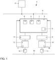
- the single figure shows a schematic block diagram of a device for piloted driving.
- the device 1 for piloted driving of a motor vehicle comprises a superordinate control device 2 and a steering control device 3, which are connected to one another via a bus system 4.
- the higher-level control device 2 is then optionally also connected to a brake control device, an engine control device and / or further control devices via the bus system 4.
- a first controller 5, a second controller 6, a monitoring unit 7 and a diagnostic unit 8 are integrated in the steering control device 3.
- the steering control device 3 is connected to first power electronics 9 and second power electronics 10.
- the first power electronics 9 generate a control current for a first electric motor 11
- the second power electronics 10 generate a control current for the second electric motor 12.
- the first electric motor 11 and the second electric motor 12 are connected to a rack 15 via gears 13, 14. Next point both the first electric motor 11 and the second electric motor 12 each have a rotor position sensor 16, 17.
- the higher-level control unit 2 determines a desired steering intervention in order to follow a trajectory.
- the higher-level control device 2 transmits a target actuator output variable (e.g. a target position of the rack 13), a target time and a tolerance band to the steering control device 3.
- the transmitted data are transmitted to the monitoring unit 7.
- the first controller 5 receives the setpoint actuator output variable and determines a control current with which the power electronics 9 and 10 each have to control the electric motors 11, 12 so that the desired setpoint actuator output variable is set.
- the first controller 5 is designed as a complex controller (e.g. as a PID controller).
- the actual actuator output variable is determined by means of the rotor position sensors 16, 17 and transmitted to the monitoring unit 7.
- the monitoring unit 7 now compares whether an actual actuator output variable has now been set within the tolerance band in the target time. If this is not the case, this indicates a software error in the first controller 5. Software error because the hardware is continuously monitored via the diagnostic unit 8. The monitoring unit 7 then deactivates the first controller 5 and activates the second controller 6, which is simpler. The second controller 6 then determines the desired control signals for the power electronics 9, 10. It can be provided that only emergency operation is carried out by means of the second controller 6 in order to bring the motor vehicle to a safe standstill.
- the second controller 6 is a simple controller and is designed, for example, as a simple P controller.
Landscapes
- Engineering & Computer Science (AREA)
- Chemical & Material Sciences (AREA)
- Combustion & Propulsion (AREA)
- Transportation (AREA)
- Mechanical Engineering (AREA)
- Steering Control In Accordance With Driving Conditions (AREA)
Description
- Die Erfindung betrifft eine Vorrichtung und ein Verfahren zum pilotierten Fahren eines Kraftfahrzeugs.
- Unter pilotiertem Fahren wird ein voll automatisiertes Fahren verstanden, bei dem der Fahrer nicht mehr als Rückfallebene zur Verfügung steht. Dabei wird die gesamte Quer- und Längsdynamik wie beispielsweise Lenkeingriffe und Beschleunigungen durch Aktoren umgesetzt, die von zugeordneten Reglern Steuersignale erhalten. Ein übergeordnetes Steuergerät ist dabei für die Trajektorien-Planung zuständig, wobei dann diese geplanten Trajektorien automatisiert abgefahren werden.
- Neben den Sicherheitsaspekten spielen auch Komfortaspekte dabei eine Rolle, die im Ergebnis dazu führen, dass die Regler, die beispielsweise die Ansteuersignale für eine Lenk-Aktorik ermitteln, sehr komplex sind. Diese berücksichtigen bei der Umsetzung einer aktuellen Lenkanforderung weitere Eingangsgrößen wie z.B. die aktuelle und zukünftige Fahrgeschwindigkeit, den aktuellen Lenkwinkel und einen zukünftigen Lenkwinkel sowie vorangegangene Eingangsgrößen (wie z. B. Lenkwinkel und/oder Fahrgeschwindigkeit). Ein Problem solcher komplexer Regler ist, dass diese nur schwer oder gar nicht vollständig testbar sind.
- Aus der
EP 0 856 453 A2 ist eine gattungsgemäße Vorrichtung zum pilotierten Fahren eines Kraftfahrzeugs bekannt. - Aus der
US 2016/332660 A1 ist ein Lenkungssystem bekannt, mit einem Lenkungssteuergerät, in dem eine Überwachungseinheit und Regelalgorithmen integriert sind. Dabei werden Rotorlage-Daten eines Rotorlagesensors als Ist-Aktorausgangsgröße ermittelt. - Aus der
DE 121 2013 006 263 T5 - Der Erfindung liegt das technische Problem zugrunde, eine Vorrichtung zum pilotierten Fahren eines Kraftfahrzeugs zu schaffen, bei dem die Sicherheit erhöht wird. Ein weiteres Problem ist es, ein geeignetes Verfahren zur Verfügung zu stellen.
- Die Lösung des technischen Problems ergibt sich durch eine Vorrichtung mit den Merkmalen des Anspruchs 1 sowie ein Verfahren mit den Merkmalen des Anspruchs 10. Weitere vorteilhafte Ausgestaltungen der Erfindung ergeben sich aus den Unteransprüchen.
- Hierzu umfasst die Vorrichtung zum pilotierten Fahren eines Kraftfahrzeugs mindestens ein übergeordnetes Steuergerät, einen ersten Regler, einen zweiten Regler, mindestens einen Aktor, eine Einheit zur Erfassung mindestens einer Ist-Aktorausgangsgröße des Aktors sowie eine Überwachungseinheit. Das übergeordnete Steuergerät ist dabei derart ausgebildet, eine Soll-Aktorausgangsgröße zu ermitteln und an den ersten Regler sowie die Überwachungseinheit zu übermitteln. Der erste Regler ist derart ausgebildet, aufgrund der Soll-Aktorausgangsgröße sowie mindestens einer weiteren Eingangsgröße ein Steuersignal für den Aktor zu ermitteln. Die Überwachungseinheit und/oder das übergeordnete Steuergerät sind derart ausgebildet, dass bei einer vorgegebenen Abweichung der Ist-Aktorausgangsgröße von der Soll-Aktorausgangsgröße der erste Regler deaktiviert und der zweite Regler aktiviert wird, wobei der zweite Regler mindestens eine Eingangsgröße weniger als der erste Regler aufweist. Der Grundgedanke der Erfindung ist, dem komplexen ersten Regler, bei dem insbesondere Software-Fehler nicht gänzlich ausschließbar sind, durch einen zweiten einfachen Regler abzusichern, der voll durchgetestet werden kann. Durch die Verwendung der Aktorausgangsgröße reagiert die Vorrichtung dabei sehr schnell auf Fehler des Reglers.
- In einer Ausführungsform ist das übergeordnete Steuergerät derart ausgebildet, neben der Soll-Aktorausgangsgröße eine Soll-Zeit und ein Toleranz-Band für die Soll-Aktorausgangsgröße an die Überwachungseinheit zu übermitteln, wobei Soll-Zeit und/oder Toleranz-Band je nach Fahraufgabe angepasst werden können.
- In einer weiteren Ausführungsform erfolgt bei zeitkritischen Abweichungen die Deaktivierung des ersten Reglers und die Aktivierung des zweiten Reglers durch die Überwachungseinheit. Zeitkritische Abweichungen sind insbesondere Abweichungen bei kurzen Soll-Zeiten, wo also beispielsweise ein Lenkeingriff schnell umgesetzt werden soll. Bei Abweichungen, wo die Fahrsituation weniger zeitkritisch ist, kann die Deaktivierung auch durch das übergeordnete Steuergerät erfolgen.
- In einer weiteren Ausführungsform weist die Vorrichtung einen weiteren Aktor auf, wobei der weitere Aktor vom ersten und/oder vom zweiten Regler angesteuert wird. In einer Ausführungsform werden also stets beide Aktoren verwendet. Alternativ kann vorgesehen sein, dass dem zweiten Regler sein eigener weiterer Aktor zugeordnet ist, sodass mit der Umschaltung der Regler auch die Aktoren umgeschaltet werden. Auch ist es möglich, dass der weitere Aktor nur vom ersten Regler angesteuert wird, sodass dieser mit der Deaktivierung des ersten Reglers auch deaktiviert wird.
- In einer weiteren Ausführungsform ist der mindestens eine Aktor als Elektromotor zur Einstellung eines Lenkwinkels des Kraftfahrzeugs ausgebildet. Dabei ist der Elektromotor beispielsweise über ein Getriebe mit einer Zahnstange verbunden, die dann die lenkbaren Räder verstellt. Die Soll- bzw. Ist-Aktorausgangsgröße kann dann beispielsweise eine Zahnstangenposition sein.
- In einer weiteren Ausführungsform ist dem Elektromotor ein Lenkungssteuergerät zugeordnet, wobei die Überwachungseinheit und/oder der erste Regler in dem Lenkungssteuergerät integriert sind.
- Zusätzlich kann auch der zweite Regler in das Lenkungssteuergerät integriert sein. Dabei kann weiter vorgesehen sein, dass der erste und zweite Regler mindestens teilweise auf gemeinsame Hardware-Komponenten zurückgreifen.
- In einer weiteren Ausführungsform ist die Einheit zur Erfassung der Ist-Aktorausgangsgröße als Rotorlagesensor ausgebildet. Aus den Daten des Rotorlagesensors lässt sich dann beispielsweise die Zahnstangenposition ermitteln.
- In einer weiteren Ausführungsform ist dem ersten Regler eine Diagnoseeinheit zur Erfassung von Bauteilefehlern zugeordnet, um Hardware-Defekte zu erkennen.
- Die Erfindung wird nachfolgend anhand eines bevorzugten Ausführungsbeispiels näher erläutert. Die einzige Figur zeigt ein schematisches Blockschaltbild einer Vorrichtung zum pilotierten Fahren.
- Die Vorrichtung 1 zum pilotierten Fahren eines Kraftfahrzeugs umfasst ein übergeordnetes Steuergerät 2 und ein Lenkungssteuergerät 3, die über ein Bussystem 4 miteinander verbunden sind. Über das Bussystem 4 ist dann das übergeordnete Steuergerät 2 gegebenenfalls noch mit einem Bremsensteuergerät, einem Motorsteuergerät und/oder weiteren Steuergeräten verbunden.
- In dem Lenkungssteuergerät 3 ist ein erster Regler 5, ein zweiter Regler 6, eine Überwachungseinheit 7 und eine Diagnoseeinheit 8 integriert. Ausgangsseitig ist das Lenkungssteuergerät 3 mit einer ersten Leistungselektronik 9 und einer zweiten Leistungselektronik 10 verbunden. Die erste Leistungselektronik 9 erzeugt einen Steuerstrom für einen ersten Elektromotor 11 und die zweite Leistungselektronik 10 erzeugt einen Steuerstrom für den zweiten Elektromotor 12. Über Getriebe 13, 14 sind der erste Elektromotor 11 und der zweite Elektromotor 12 mit einer Zahnstange 15 verbunden. Weiter weisen sowohl der erste Elektromotor 11 als auch der zweite Elektromotor 12 jeweils einen Rotorlagesensor 16, 17 auf.
- Das übergeordnete Steuergerät 2 ermittelt einen gewünschten Lenkeingriff, um eine Trajektorie abzufahren. Das übergeordnete Steuergerät 2 übermittelt dann an das Lenkungssteuergerät 3 eine Soll-Aktorausgangsgröße (z.B. eine Soll-Position der Zahnstange 13), eine Soll-Zeit und ein Toleranz-Band. Die übermittelten Daten werden der Überwachungseinheit 7 übermittelt. Der erste Regler 5 erhält die Soll-Aktorausgangsgröße und ermittelt einen Steuerstrom, mit dem die Leistungselektronik 9 sowie 10 jeweils die Elektromotoren 11, 12 ansteuern müssen, damit sich die gewünschte Soll-Aktorausgangsgröße einstellt. Der erste Regler 5 ist dabei als komplexer Regler ausgebildet (z.B. als PID-Regler). Mittels der Rotorlagesensoren 16, 17 wird die Ist-Aktorausgangsgröße ermittelt und an die Überwachungseinheit 7 übermittelt. Die Überwachungseinheit 7 vergleicht nun, ob nun in der Soll-Zeit sich eine Ist-Aktorausgangsgröße innerhalb des Toleranz-Bandes eingestellt. Ist dies nicht der Fall, so spricht dies für einen Software-Fehler des ersten Reglers 5. Software-Fehler deshalb, weil über die Diagnoseeinheit 8 die Hardware kontinuierlich überwacht wird. Die Überwachungseinheit 7 deaktiviert daraufhin den ersten Regler 5 und aktiviert den zweiten Regler 6, der einfacher ist. Der zweite Regler 6 ermittelt dann die gewünschten Steuersignale für die Leistungselektroniken 9, 10. Dabei kann vorgesehen sein, dass mittels des zweiten Reglers 6 nur ein Notbetrieb durchgeführt wird, um das Kraftfahrzeug sicher zum Stillstand zu bringen. Der zweite Regler 6 ist dabei ein einfacher Regler und ist beispielsweise als einfacher P-Regler ausgebildet.
Claims (10)
- Vorrichtung (1) zum pilotierten Fahren eines Kraftfahrzeugs, umfassend mindestens ein übergeordnetes Steuergerät (2), einen ersten Regler (5), einen zweiten Regler (6), mindestens einen Aktor, eine Einheit zur Erfassung mindestens einer Ist-Aktorausgangsgröße des Aktors sowie eine Überwachungseinheit (7), wobei das übergeordnete Steuergerät (2) derart ausgebildet ist, eine Soll-Aktorausgangsgröße zu ermitteln und an den ersten Regler (5) sowie die Überwachungseinheit (7) zu übermitteln, wobei der erste Regler (5) derart ausgebildet ist, aufgrund der Soll-Aktorausgangsgröße sowie mindestens einer weiteren Größe ein Steuersignal für den Aktor zu ermitteln, wobei die Überwachungseinheit (7) und/oder das übergeordnete Steuergerät (2) derart ausgebildet sind, dass bei einer vorgegebenen Abweichung der Ist-Aktorausgangsgröße von der Soll-Aktorausgangsgröße der erste Regler (5) deaktiviert und der zweite Regler (6) aktiviert wird,
dadurch gekennzeichnet, dass
der zweite Regler mindestens eine Eingangsgröße weniger als der erste Regler aufweist. - Vorrichtung nach Anspruch 1, dadurch gekennzeichnet, dass das übergeordnete Steuergerät (2) derart ausgebildet ist, neben der Soll-Aktorausgangsgröße eine Soll-Zeit und ein Toleranz-Band für die Soll-Aktorausgangsgröße an die Überwachungseinheit (7) zu übermitteln.
- Vorrichtung nach Anspruch 1 oder 2, dadurch gekennzeichnet, dass bei zeitkritischen Abweichungen die Deaktivierung des ersten Reglers (5) und die Aktivierung des zweiten Reglers (6) durch die Überwachungseinheit (7) erfolgt.
- Vorrichtung nach einem der vorangegangenen Ansprüche, dadurch gekennzeichnet, dass die Vorrichtung (1) einem weiteren Aktor aufweist, wobei der weitere Aktor vom ersten und/oder vom zweiten Regler angesteuert wird.
- Vorrichtung nach einem der vorangegangenen Ansprüche, dadurch gekennzeichnet, dass der mindestens eine Aktor als Elektromotor (11, 12) zur Einstellung eines Lenkwinkels des Kraftfahrzeugs ausgebildet ist.
- Vorrichtung nach Anspruch 5, dadurch gekennzeichnet, dass dem Elektromotor (11, 12) ein Lenkungssteuergerät (3) zugeordnet ist, wobei die Überwachungseinheit (7) und/oder der erste Regler (5) in dem Lenkungssteuergerät (3) integriert sind.
- Vorrichtung nach Anspruch 6, dadurch gekennzeichnet, dass zusätzlich der zweite Regler (6) in das Lenkungssteuergerät (3) integriert ist.
- Vorrichtung nach einem der Ansprüche 5 bis 7, dadurch gekennzeichnet, dass die Einheit zur Erfassung der Ist-Aktorausgangsgröße als Rotorlagesensor (16, 17) ausgebildet ist.
- Vorrichtung nach einem der vorangegangenen Ansprüche, dadurch gekennzeichnet, dass dem ersten Regler (5) eine Diagnoseeinheit (8) zur Erfassung von Bauteilefehlern zugeordnet ist.
- Verfahren zum pilotierten Fahren eines Kraftfahrzeugs mittels mindestens einem übergeordneten Steuergerät (2), einem ersten Regler (5), einem zweiten Regler (6), mindestens einem Aktor, einer Einheit zur Erfassung mindestens einer Ist-Aktorausgangsgröße des Aktors sowie einer Überwachungseinheit (7), wobei das übergeordnete Steuergerät (2) eine Soll-Aktorausgangsgröße ermittelt und an den ersten Regler (5) und die Überwachungseinheit (7) übermittelt, wobei der erste Regler (5) aufgrund der Soll-Aktorausgangsgröße sowie mindestens einer weiteren Größe ein Steuersignal für den Aktor ermittelt und an diesen übermittelt, wobei die Überwachungseinheit (7) und/oder das übergeordnete Steuergerät (2) bei einer vorgegebenen Abweichung der Ist-Aktorausgangsgröße von der Soll-Aktorausgangsgröße den ersten Regler (5) deaktiviert und den zweiten Regler (6) aktiviert,
dadurch gekennzeichnet, dass
der zweite Regler (6) mindestens eine Eingangsgröße weniger als der erste Regler aufweist.
Applications Claiming Priority (2)
| Application Number | Priority Date | Filing Date | Title |
|---|---|---|---|
| DE102017209720.5A DE102017209720A1 (de) | 2017-06-08 | 2017-06-08 | Vorrichtung und Verfahren zum pilotierten Fahren eines Kraftfahrzeugs |
| PCT/EP2018/063104 WO2018224290A1 (de) | 2017-06-08 | 2018-05-18 | Vorrichtung und verfahren zum pilotierten fahren eines kraftfahrzeugs |
Publications (2)
| Publication Number | Publication Date |
|---|---|
| EP3634833A1 EP3634833A1 (de) | 2020-04-15 |
| EP3634833B1 true EP3634833B1 (de) | 2021-07-07 |
Family
ID=62245274
Family Applications (1)
| Application Number | Title | Priority Date | Filing Date |
|---|---|---|---|
| EP18727230.7A Active EP3634833B1 (de) | 2017-06-08 | 2018-05-18 | Vorrichtung und verfahren zum pilotierten fahren eines kraftfahrzeugs |
Country Status (3)
| Country | Link |
|---|---|
| EP (1) | EP3634833B1 (de) |
| DE (1) | DE102017209720A1 (de) |
| WO (1) | WO2018224290A1 (de) |
Families Citing this family (3)
| Publication number | Priority date | Publication date | Assignee | Title |
|---|---|---|---|---|
| DE102018218837B4 (de) | 2018-11-05 | 2020-06-18 | Mando Corporation | Radgeschwindigkeitssensorsystem, ein das Radgeschwindigkeitssensorsystem enthaltendes Fahrzeug und Verfahren zum Verarbeiten von Radgeschwindigkeitssignalen |
| DE102019202627B3 (de) * | 2019-02-27 | 2020-04-16 | Robert Bosch Gmbh | Verfahren zum Betrieb einer Lenkungssteuervorrichtung zur Ansteuerung einer elektrischen Lenkung und Lenkungssteuervorrichtung |
| DE102019134258A1 (de) * | 2019-12-13 | 2021-05-06 | Daimler Ag | Verfahren zum Steuern einer Fahrfunktion eines Fahrzeugs |
Family Cites Families (6)
| Publication number | Priority date | Publication date | Assignee | Title |
|---|---|---|---|---|
| DE19703846A1 (de) * | 1997-02-01 | 1998-08-06 | Claas Ohg | Elektrohydraulisches Lenksystem für Fahrzeuge |
| DE102008004205A1 (de) * | 2008-01-14 | 2009-07-16 | Robert Bosch Gmbh | Schaltungsanordnung und Verfahren zur Fehlerbehandlung in Echtzeitsystemen |
| JP6017588B2 (ja) * | 2012-12-28 | 2016-11-02 | 本田技研工業株式会社 | 車両用操舵装置 |
| DE102013201702C5 (de) * | 2013-02-01 | 2017-03-23 | Mtu Friedrichshafen Gmbh | Verfahren und Anordnung zur Steuerung einer Brennkraftmaschine |
| DE102013202253A1 (de) * | 2013-02-12 | 2014-08-14 | Paravan Gmbh | Schaltung zur Steuerung eines Beschleunigungs-, Brems- und Lenksystems eines Fahrzeugs |
| WO2015125617A1 (ja) * | 2014-02-24 | 2015-08-27 | 日立オートモティブシステムズステアリング株式会社 | 車両搭載機器の制御装置およびパワーステアリング装置 |
-
2017
- 2017-06-08 DE DE102017209720.5A patent/DE102017209720A1/de not_active Withdrawn
-
2018
- 2018-05-18 EP EP18727230.7A patent/EP3634833B1/de active Active
- 2018-05-18 WO PCT/EP2018/063104 patent/WO2018224290A1/de unknown
Also Published As
| Publication number | Publication date |
|---|---|
| EP3634833A1 (de) | 2020-04-15 |
| DE102017209720A1 (de) | 2019-01-10 |
| WO2018224290A1 (de) | 2018-12-13 |
Similar Documents
| Publication | Publication Date | Title |
|---|---|---|
| EP2766235B1 (de) | Fahrzeug und verfahren zum steuern eines fahrzeugs | |
| EP3634833B1 (de) | Vorrichtung und verfahren zum pilotierten fahren eines kraftfahrzeugs | |
| EP2648955B1 (de) | Verfahren und vorrichtung zum einleiten eines notlaufbetriebs eines kraftfahrzeugs | |
| EP3256364B1 (de) | Verfahren zum anlernen zulässiger lenkwinkel bei einer lenkeinrichtung eines kraftfahrzeugs | |
| WO2011110649A1 (de) | Verfahren zum ersetzen einer bestehenden leiteinrichtung in einem automatisierungssystem durch eine neue leiteinrichtung und dazu ausgebildetes automatisierungssystem | |
| EP3747733B1 (de) | Verfahren zum betreiben eines lenksystems | |
| DE102014221007A1 (de) | Vorrichtung und Verfahren zum Betreiben eines Fahrzeugs | |
| DE102014013173A1 (de) | Verfahren zum zumindest teilautonomen Betrieb eines Fahrzeugs und Fahrerassistenzsystem | |
| DE102016221565B4 (de) | Verfahren zum Unterscheiden zwischen gewollten Lenkbewegungen eines Fahrers zur Beeinflussung eines gewollten Fahrpfades eines Kraftfahrzeuges von Korrekturlenkbewegungen des Fahrers als Reaktion auf unerwartete Abweichungen des Kraftfahrzeuges vom gewollten Fahrpfad sowie maschinenlesbarer Datenträger | |
| EP1313664A1 (de) | Redundantes sicherheitssystem eines fahrzeuges | |
| EP3727998B1 (de) | Verfahren zum betreiben eines steer-by-wire-lenksystems für ein kraftfahrzeug sowie lenksystem für ein kraftfahrzeug | |
| EP1868838B1 (de) | Flurförderfahrzeug | |
| DE102008036772A1 (de) | Verfahren zum Betreiben eines Fahrzeugs, Assistenzvorrichtung für ein Fahrzeug, Koordinationsvorrichtung zum Ansteuern einer Querführungsvorrichtung eines Fahrzeugs und Assistenzsystem eines Fahrzeugs | |
| EP2822838B1 (de) | Verfahren zum automatisierten einparken eines mit einem aktiven parklenk-assistenzsystem und einer überlagerungslenkvorrichtung ausgestatteten kraftfahrzeugs | |
| EP3470301B1 (de) | Lenkungssteuersystem für ein lenksystem eines kraftfahrzeuges sowie verfahren zum betreiben eines lenkungssteuersystems | |
| DE102014212289A1 (de) | Autonome Steuerung eines Kraftfahrzeugs | |
| DE102014009715B4 (de) | Verfahren zum Betreiben einer Antriebseinrichtung eines Kraftfahrzeugs sowie entsprechende Antriebseinrichtung | |
| DE102012022801B4 (de) | Verfahren zur Lenkungsüberwachung und Lenksystem | |
| DE102004009467A1 (de) | Steuerungssystem für ein Fahrzeug | |
| DE102013214401B4 (de) | Verfahren und Vorrichtung zum Betreiben eines Fahrerassistenzsystems | |
| WO2019068891A1 (de) | Verfahren zum betreiben eines lenksystems und lenksystem | |
| EP2261096A1 (de) | Verfahren zur Fahreridentifikation in einem Fahrzeug | |
| EP2496451B1 (de) | VERFAHREN ZUR EINSTELLUNG EINES GRENZWERTS EINER FAHRZEUGZUSTANDSGRÖßE BEI EINEM UNFALL | |
| WO2018108668A1 (de) | Verfahren zur feststellung der zahnstangenposition in einem lenksystem mit elektrischem servomotor | |
| DE102017109175A1 (de) | Steuereinrichtung, Fahrerassistenzsystem, Kraftfahrzeug und Verfahren zum Steuern einer Fahrerassistenzfunktion |
Legal Events
| Date | Code | Title | Description |
|---|---|---|---|
| STAA | Information on the status of an ep patent application or granted ep patent |
Free format text: STATUS: UNKNOWN |
|
| STAA | Information on the status of an ep patent application or granted ep patent |
Free format text: STATUS: THE INTERNATIONAL PUBLICATION HAS BEEN MADE |
|
| PUAI | Public reference made under article 153(3) epc to a published international application that has entered the european phase |
Free format text: ORIGINAL CODE: 0009012 |
|
| STAA | Information on the status of an ep patent application or granted ep patent |
Free format text: STATUS: REQUEST FOR EXAMINATION WAS MADE |
|
| 17P | Request for examination filed |
Effective date: 20200108 |
|
| AK | Designated contracting states |
Kind code of ref document: A1 Designated state(s): AL AT BE BG CH CY CZ DE DK EE ES FI FR GB GR HR HU IE IS IT LI LT LU LV MC MK MT NL NO PL PT RO RS SE SI SK SM TR |
|
| AX | Request for extension of the european patent |
Extension state: BA ME |
|
| DAV | Request for validation of the european patent (deleted) | ||
| DAX | Request for extension of the european patent (deleted) | ||
| RIC1 | Information provided on ipc code assigned before grant |
Ipc: B60W 50/029 20120101ALI20201216BHEP Ipc: B62D 5/04 20060101ALI20201216BHEP Ipc: B62D 15/02 20060101ALI20201216BHEP Ipc: B62D 1/28 20060101AFI20201216BHEP |
|
| GRAP | Despatch of communication of intention to grant a patent |
Free format text: ORIGINAL CODE: EPIDOSNIGR1 |
|
| STAA | Information on the status of an ep patent application or granted ep patent |
Free format text: STATUS: GRANT OF PATENT IS INTENDED |
|
| INTG | Intention to grant announced |
Effective date: 20210127 |
|
| GRAS | Grant fee paid |
Free format text: ORIGINAL CODE: EPIDOSNIGR3 |
|
| GRAA | (expected) grant |
Free format text: ORIGINAL CODE: 0009210 |
|
| STAA | Information on the status of an ep patent application or granted ep patent |
Free format text: STATUS: THE PATENT HAS BEEN GRANTED |
|
| AK | Designated contracting states |
Kind code of ref document: B1 Designated state(s): AL AT BE BG CH CY CZ DE DK EE ES FI FR GB GR HR HU IE IS IT LI LT LU LV MC MK MT NL NO PL PT RO RS SE SI SK SM TR |
|
| REG | Reference to a national code |
Ref country code: GB Ref legal event code: FG4D Free format text: NOT ENGLISH |
|
| REG | Reference to a national code |
Ref country code: AT Ref legal event code: REF Ref document number: 1408319 Country of ref document: AT Kind code of ref document: T Effective date: 20210715 |
|
| REG | Reference to a national code |
Ref country code: DE Ref legal event code: R096 Ref document number: 502018006043 Country of ref document: DE |
|
| REG | Reference to a national code |
Ref country code: IE Ref legal event code: FG4D Free format text: LANGUAGE OF EP DOCUMENT: GERMAN |
|
| REG | Reference to a national code |
Ref country code: SE Ref legal event code: TRGR |
|
| REG | Reference to a national code |
Ref country code: LT Ref legal event code: MG9D |
|
| REG | Reference to a national code |
Ref country code: NL Ref legal event code: MP Effective date: 20210707 |
|
| PG25 | Lapsed in a contracting state [announced via postgrant information from national office to epo] |
Ref country code: RS Free format text: LAPSE BECAUSE OF FAILURE TO SUBMIT A TRANSLATION OF THE DESCRIPTION OR TO PAY THE FEE WITHIN THE PRESCRIBED TIME-LIMIT Effective date: 20210707 Ref country code: ES Free format text: LAPSE BECAUSE OF FAILURE TO SUBMIT A TRANSLATION OF THE DESCRIPTION OR TO PAY THE FEE WITHIN THE PRESCRIBED TIME-LIMIT Effective date: 20210707 Ref country code: FI Free format text: LAPSE BECAUSE OF FAILURE TO SUBMIT A TRANSLATION OF THE DESCRIPTION OR TO PAY THE FEE WITHIN THE PRESCRIBED TIME-LIMIT Effective date: 20210707 Ref country code: HR Free format text: LAPSE BECAUSE OF FAILURE TO SUBMIT A TRANSLATION OF THE DESCRIPTION OR TO PAY THE FEE WITHIN THE PRESCRIBED TIME-LIMIT Effective date: 20210707 Ref country code: NO Free format text: LAPSE BECAUSE OF FAILURE TO SUBMIT A TRANSLATION OF THE DESCRIPTION OR TO PAY THE FEE WITHIN THE PRESCRIBED TIME-LIMIT Effective date: 20211007 Ref country code: NL Free format text: LAPSE BECAUSE OF FAILURE TO SUBMIT A TRANSLATION OF THE DESCRIPTION OR TO PAY THE FEE WITHIN THE PRESCRIBED TIME-LIMIT Effective date: 20210707 Ref country code: PT Free format text: LAPSE BECAUSE OF FAILURE TO SUBMIT A TRANSLATION OF THE DESCRIPTION OR TO PAY THE FEE WITHIN THE PRESCRIBED TIME-LIMIT Effective date: 20211108 Ref country code: BG Free format text: LAPSE BECAUSE OF FAILURE TO SUBMIT A TRANSLATION OF THE DESCRIPTION OR TO PAY THE FEE WITHIN THE PRESCRIBED TIME-LIMIT Effective date: 20211007 Ref country code: LT Free format text: LAPSE BECAUSE OF FAILURE TO SUBMIT A TRANSLATION OF THE DESCRIPTION OR TO PAY THE FEE WITHIN THE PRESCRIBED TIME-LIMIT Effective date: 20210707 |
|
| PG25 | Lapsed in a contracting state [announced via postgrant information from national office to epo] |
Ref country code: PL Free format text: LAPSE BECAUSE OF FAILURE TO SUBMIT A TRANSLATION OF THE DESCRIPTION OR TO PAY THE FEE WITHIN THE PRESCRIBED TIME-LIMIT Effective date: 20210707 Ref country code: LV Free format text: LAPSE BECAUSE OF FAILURE TO SUBMIT A TRANSLATION OF THE DESCRIPTION OR TO PAY THE FEE WITHIN THE PRESCRIBED TIME-LIMIT Effective date: 20210707 Ref country code: GR Free format text: LAPSE BECAUSE OF FAILURE TO SUBMIT A TRANSLATION OF THE DESCRIPTION OR TO PAY THE FEE WITHIN THE PRESCRIBED TIME-LIMIT Effective date: 20211008 |
|
| REG | Reference to a national code |
Ref country code: DE Ref legal event code: R097 Ref document number: 502018006043 Country of ref document: DE |
|
| PG25 | Lapsed in a contracting state [announced via postgrant information from national office to epo] |
Ref country code: DK Free format text: LAPSE BECAUSE OF FAILURE TO SUBMIT A TRANSLATION OF THE DESCRIPTION OR TO PAY THE FEE WITHIN THE PRESCRIBED TIME-LIMIT Effective date: 20210707 |
|
| PLBE | No opposition filed within time limit |
Free format text: ORIGINAL CODE: 0009261 |
|
| STAA | Information on the status of an ep patent application or granted ep patent |
Free format text: STATUS: NO OPPOSITION FILED WITHIN TIME LIMIT |
|
| PG25 | Lapsed in a contracting state [announced via postgrant information from national office to epo] |
Ref country code: SM Free format text: LAPSE BECAUSE OF FAILURE TO SUBMIT A TRANSLATION OF THE DESCRIPTION OR TO PAY THE FEE WITHIN THE PRESCRIBED TIME-LIMIT Effective date: 20210707 Ref country code: SK Free format text: LAPSE BECAUSE OF FAILURE TO SUBMIT A TRANSLATION OF THE DESCRIPTION OR TO PAY THE FEE WITHIN THE PRESCRIBED TIME-LIMIT Effective date: 20210707 Ref country code: RO Free format text: LAPSE BECAUSE OF FAILURE TO SUBMIT A TRANSLATION OF THE DESCRIPTION OR TO PAY THE FEE WITHIN THE PRESCRIBED TIME-LIMIT Effective date: 20210707 Ref country code: EE Free format text: LAPSE BECAUSE OF FAILURE TO SUBMIT A TRANSLATION OF THE DESCRIPTION OR TO PAY THE FEE WITHIN THE PRESCRIBED TIME-LIMIT Effective date: 20210707 Ref country code: CZ Free format text: LAPSE BECAUSE OF FAILURE TO SUBMIT A TRANSLATION OF THE DESCRIPTION OR TO PAY THE FEE WITHIN THE PRESCRIBED TIME-LIMIT Effective date: 20210707 Ref country code: AL Free format text: LAPSE BECAUSE OF FAILURE TO SUBMIT A TRANSLATION OF THE DESCRIPTION OR TO PAY THE FEE WITHIN THE PRESCRIBED TIME-LIMIT Effective date: 20210707 |
|
| 26N | No opposition filed |
Effective date: 20220408 |
|
| PG25 | Lapsed in a contracting state [announced via postgrant information from national office to epo] |
Ref country code: IT Free format text: LAPSE BECAUSE OF FAILURE TO SUBMIT A TRANSLATION OF THE DESCRIPTION OR TO PAY THE FEE WITHIN THE PRESCRIBED TIME-LIMIT Effective date: 20210707 |
|
| REG | Reference to a national code |
Ref country code: CH Ref legal event code: PL |
|
| REG | Reference to a national code |
Ref country code: BE Ref legal event code: MM Effective date: 20220531 |
|
| PG25 | Lapsed in a contracting state [announced via postgrant information from national office to epo] |
Ref country code: MC Free format text: LAPSE BECAUSE OF FAILURE TO SUBMIT A TRANSLATION OF THE DESCRIPTION OR TO PAY THE FEE WITHIN THE PRESCRIBED TIME-LIMIT Effective date: 20210707 Ref country code: LU Free format text: LAPSE BECAUSE OF NON-PAYMENT OF DUE FEES Effective date: 20220518 Ref country code: LI Free format text: LAPSE BECAUSE OF NON-PAYMENT OF DUE FEES Effective date: 20220531 Ref country code: CH Free format text: LAPSE BECAUSE OF NON-PAYMENT OF DUE FEES Effective date: 20220531 |
|
| PG25 | Lapsed in a contracting state [announced via postgrant information from national office to epo] |
Ref country code: IE Free format text: LAPSE BECAUSE OF NON-PAYMENT OF DUE FEES Effective date: 20220518 |
|
| PG25 | Lapsed in a contracting state [announced via postgrant information from national office to epo] |
Ref country code: BE Free format text: LAPSE BECAUSE OF NON-PAYMENT OF DUE FEES Effective date: 20220531 |
|
| P01 | Opt-out of the competence of the unified patent court (upc) registered |
Effective date: 20230523 |
|
| PGFP | Annual fee paid to national office [announced via postgrant information from national office to epo] |
Ref country code: FR Payment date: 20230523 Year of fee payment: 6 Ref country code: DE Payment date: 20230531 Year of fee payment: 6 |
|
| PGFP | Annual fee paid to national office [announced via postgrant information from national office to epo] |
Ref country code: SE Payment date: 20230524 Year of fee payment: 6 |
|
| PGFP | Annual fee paid to national office [announced via postgrant information from national office to epo] |
Ref country code: GB Payment date: 20230523 Year of fee payment: 6 |
|
| PG25 | Lapsed in a contracting state [announced via postgrant information from national office to epo] |
Ref country code: MK Free format text: LAPSE BECAUSE OF FAILURE TO SUBMIT A TRANSLATION OF THE DESCRIPTION OR TO PAY THE FEE WITHIN THE PRESCRIBED TIME-LIMIT Effective date: 20210707 Ref country code: CY Free format text: LAPSE BECAUSE OF FAILURE TO SUBMIT A TRANSLATION OF THE DESCRIPTION OR TO PAY THE FEE WITHIN THE PRESCRIBED TIME-LIMIT Effective date: 20210707 |