EP3634712B1 - Procede de fabrication d'un conduit d'admission d'air - Google Patents
Procede de fabrication d'un conduit d'admission d'air Download PDFInfo
- Publication number
- EP3634712B1 EP3634712B1 EP18725291.1A EP18725291A EP3634712B1 EP 3634712 B1 EP3634712 B1 EP 3634712B1 EP 18725291 A EP18725291 A EP 18725291A EP 3634712 B1 EP3634712 B1 EP 3634712B1
- Authority
- EP
- European Patent Office
- Prior art keywords
- duct
- mold
- air
- tubular sheet
- manufacturing
- Prior art date
- Legal status (The legal status is an assumption and is not a legal conclusion. Google has not performed a legal analysis and makes no representation as to the accuracy of the status listed.)
- Active
Links
Images


Classifications
-
- F—MECHANICAL ENGINEERING; LIGHTING; HEATING; WEAPONS; BLASTING
- F24—HEATING; RANGES; VENTILATING
- F24F—AIR-CONDITIONING; AIR-HUMIDIFICATION; VENTILATION; USE OF AIR CURRENTS FOR SCREENING
- F24F7/00—Ventilation
- F24F7/04—Ventilation with ducting systems, e.g. by double walls; with natural circulation
-
- B—PERFORMING OPERATIONS; TRANSPORTING
- B29—WORKING OF PLASTICS; WORKING OF SUBSTANCES IN A PLASTIC STATE IN GENERAL
- B29C—SHAPING OR JOINING OF PLASTICS; SHAPING OF MATERIAL IN A PLASTIC STATE, NOT OTHERWISE PROVIDED FOR; AFTER-TREATMENT OF THE SHAPED PRODUCTS, e.g. REPAIRING
- B29C45/00—Injection moulding, i.e. forcing the required volume of moulding material through a nozzle into a closed mould; Apparatus therefor
- B29C45/14—Injection moulding, i.e. forcing the required volume of moulding material through a nozzle into a closed mould; Apparatus therefor incorporating preformed parts or layers, e.g. injection moulding around inserts or for coating articles
- B29C45/14065—Positioning or centering articles in the mould
-
- B—PERFORMING OPERATIONS; TRANSPORTING
- B29—WORKING OF PLASTICS; WORKING OF SUBSTANCES IN A PLASTIC STATE IN GENERAL
- B29C—SHAPING OR JOINING OF PLASTICS; SHAPING OF MATERIAL IN A PLASTIC STATE, NOT OTHERWISE PROVIDED FOR; AFTER-TREATMENT OF THE SHAPED PRODUCTS, e.g. REPAIRING
- B29C45/00—Injection moulding, i.e. forcing the required volume of moulding material through a nozzle into a closed mould; Apparatus therefor
- B29C45/14—Injection moulding, i.e. forcing the required volume of moulding material through a nozzle into a closed mould; Apparatus therefor incorporating preformed parts or layers, e.g. injection moulding around inserts or for coating articles
- B29C45/14598—Coating tubular articles
- B29C45/14622—Lining the inner or outer surface of tubular articles
-
- B—PERFORMING OPERATIONS; TRANSPORTING
- B29—WORKING OF PLASTICS; WORKING OF SUBSTANCES IN A PLASTIC STATE IN GENERAL
- B29C—SHAPING OR JOINING OF PLASTICS; SHAPING OF MATERIAL IN A PLASTIC STATE, NOT OTHERWISE PROVIDED FOR; AFTER-TREATMENT OF THE SHAPED PRODUCTS, e.g. REPAIRING
- B29C45/00—Injection moulding, i.e. forcing the required volume of moulding material through a nozzle into a closed mould; Apparatus therefor
- B29C45/14—Injection moulding, i.e. forcing the required volume of moulding material through a nozzle into a closed mould; Apparatus therefor incorporating preformed parts or layers, e.g. injection moulding around inserts or for coating articles
- B29C45/14778—Injection moulding, i.e. forcing the required volume of moulding material through a nozzle into a closed mould; Apparatus therefor incorporating preformed parts or layers, e.g. injection moulding around inserts or for coating articles the article consisting of a material with particular properties, e.g. porous, brittle
- B29C45/14786—Fibrous material or fibre containing material, e.g. fibre mats or fibre reinforced material
-
- B—PERFORMING OPERATIONS; TRANSPORTING
- B29—WORKING OF PLASTICS; WORKING OF SUBSTANCES IN A PLASTIC STATE IN GENERAL
- B29C—SHAPING OR JOINING OF PLASTICS; SHAPING OF MATERIAL IN A PLASTIC STATE, NOT OTHERWISE PROVIDED FOR; AFTER-TREATMENT OF THE SHAPED PRODUCTS, e.g. REPAIRING
- B29C45/00—Injection moulding, i.e. forcing the required volume of moulding material through a nozzle into a closed mould; Apparatus therefor
- B29C45/14—Injection moulding, i.e. forcing the required volume of moulding material through a nozzle into a closed mould; Apparatus therefor incorporating preformed parts or layers, e.g. injection moulding around inserts or for coating articles
- B29C45/14778—Injection moulding, i.e. forcing the required volume of moulding material through a nozzle into a closed mould; Apparatus therefor incorporating preformed parts or layers, e.g. injection moulding around inserts or for coating articles the article consisting of a material with particular properties, e.g. porous, brittle
- B29C45/14795—Porous or permeable material, e.g. foam
-
- B—PERFORMING OPERATIONS; TRANSPORTING
- B29—WORKING OF PLASTICS; WORKING OF SUBSTANCES IN A PLASTIC STATE IN GENERAL
- B29C—SHAPING OR JOINING OF PLASTICS; SHAPING OF MATERIAL IN A PLASTIC STATE, NOT OTHERWISE PROVIDED FOR; AFTER-TREATMENT OF THE SHAPED PRODUCTS, e.g. REPAIRING
- B29C45/00—Injection moulding, i.e. forcing the required volume of moulding material through a nozzle into a closed mould; Apparatus therefor
- B29C45/17—Component parts, details or accessories; Auxiliary operations
- B29C45/26—Moulds
- B29C45/37—Mould cavity walls, i.e. the inner surface forming the mould cavity, e.g. linings
- B29C45/372—Mould cavity walls, i.e. the inner surface forming the mould cavity, e.g. linings provided with means for marking or patterning, e.g. numbering articles
-
- F—MECHANICAL ENGINEERING; LIGHTING; HEATING; WEAPONS; BLASTING
- F02—COMBUSTION ENGINES; HOT-GAS OR COMBUSTION-PRODUCT ENGINE PLANTS
- F02M—SUPPLYING COMBUSTION ENGINES IN GENERAL WITH COMBUSTIBLE MIXTURES OR CONSTITUENTS THEREOF
- F02M35/00—Combustion-air cleaners, air intakes, intake silencers, or induction systems specially adapted for, or arranged on, internal-combustion engines
- F02M35/10—Air intakes; Induction systems
- F02M35/10091—Air intakes; Induction systems characterised by details of intake ducts: shapes; connections; arrangements
-
- F—MECHANICAL ENGINEERING; LIGHTING; HEATING; WEAPONS; BLASTING
- F02—COMBUSTION ENGINES; HOT-GAS OR COMBUSTION-PRODUCT ENGINE PLANTS
- F02M—SUPPLYING COMBUSTION ENGINES IN GENERAL WITH COMBUSTIBLE MIXTURES OR CONSTITUENTS THEREOF
- F02M35/00—Combustion-air cleaners, air intakes, intake silencers, or induction systems specially adapted for, or arranged on, internal-combustion engines
- F02M35/12—Intake silencers ; Sound modulation, transmission or amplification
- F02M35/1277—Reinforcement of walls, e.g. with ribs or laminates; Walls having air gaps or additional sound damping layers
-
- F—MECHANICAL ENGINEERING; LIGHTING; HEATING; WEAPONS; BLASTING
- F02—COMBUSTION ENGINES; HOT-GAS OR COMBUSTION-PRODUCT ENGINE PLANTS
- F02M—SUPPLYING COMBUSTION ENGINES IN GENERAL WITH COMBUSTIBLE MIXTURES OR CONSTITUENTS THEREOF
- F02M35/00—Combustion-air cleaners, air intakes, intake silencers, or induction systems specially adapted for, or arranged on, internal-combustion engines
- F02M35/12—Intake silencers ; Sound modulation, transmission or amplification
- F02M35/1283—Manufacturing or assembly; Connectors; Fixations
-
- B—PERFORMING OPERATIONS; TRANSPORTING
- B29—WORKING OF PLASTICS; WORKING OF SUBSTANCES IN A PLASTIC STATE IN GENERAL
- B29C—SHAPING OR JOINING OF PLASTICS; SHAPING OF MATERIAL IN A PLASTIC STATE, NOT OTHERWISE PROVIDED FOR; AFTER-TREATMENT OF THE SHAPED PRODUCTS, e.g. REPAIRING
- B29C45/00—Injection moulding, i.e. forcing the required volume of moulding material through a nozzle into a closed mould; Apparatus therefor
- B29C45/14—Injection moulding, i.e. forcing the required volume of moulding material through a nozzle into a closed mould; Apparatus therefor incorporating preformed parts or layers, e.g. injection moulding around inserts or for coating articles
- B29C45/14008—Inserting articles into the mould
- B29C2045/14057—Inserting articles into the mould feeding inserts wrapped on a core
-
- B—PERFORMING OPERATIONS; TRANSPORTING
- B29—WORKING OF PLASTICS; WORKING OF SUBSTANCES IN A PLASTIC STATE IN GENERAL
- B29C—SHAPING OR JOINING OF PLASTICS; SHAPING OF MATERIAL IN A PLASTIC STATE, NOT OTHERWISE PROVIDED FOR; AFTER-TREATMENT OF THE SHAPED PRODUCTS, e.g. REPAIRING
- B29C45/00—Injection moulding, i.e. forcing the required volume of moulding material through a nozzle into a closed mould; Apparatus therefor
- B29C45/03—Injection moulding apparatus
- B29C45/04—Injection moulding apparatus using movable moulds or mould halves
-
- B—PERFORMING OPERATIONS; TRANSPORTING
- B29—WORKING OF PLASTICS; WORKING OF SUBSTANCES IN A PLASTIC STATE IN GENERAL
- B29C—SHAPING OR JOINING OF PLASTICS; SHAPING OF MATERIAL IN A PLASTIC STATE, NOT OTHERWISE PROVIDED FOR; AFTER-TREATMENT OF THE SHAPED PRODUCTS, e.g. REPAIRING
- B29C45/00—Injection moulding, i.e. forcing the required volume of moulding material through a nozzle into a closed mould; Apparatus therefor
- B29C45/14—Injection moulding, i.e. forcing the required volume of moulding material through a nozzle into a closed mould; Apparatus therefor incorporating preformed parts or layers, e.g. injection moulding around inserts or for coating articles
- B29C45/14467—Joining articles or parts of a single article
- B29C45/14491—Injecting material between coaxial articles, e.g. between a core and an outside sleeve for making a roll
-
- B—PERFORMING OPERATIONS; TRANSPORTING
- B29—WORKING OF PLASTICS; WORKING OF SUBSTANCES IN A PLASTIC STATE IN GENERAL
- B29K—INDEXING SCHEME ASSOCIATED WITH SUBCLASSES B29B, B29C OR B29D, RELATING TO MOULDING MATERIALS OR TO MATERIALS FOR MOULDS, REINFORCEMENTS, FILLERS OR PREFORMED PARTS, e.g. INSERTS
- B29K2023/00—Use of polyalkenes or derivatives thereof as moulding material
- B29K2023/10—Polymers of propylene
- B29K2023/12—PP, i.e. polypropylene
-
- B—PERFORMING OPERATIONS; TRANSPORTING
- B29—WORKING OF PLASTICS; WORKING OF SUBSTANCES IN A PLASTIC STATE IN GENERAL
- B29K—INDEXING SCHEME ASSOCIATED WITH SUBCLASSES B29B, B29C OR B29D, RELATING TO MOULDING MATERIALS OR TO MATERIALS FOR MOULDS, REINFORCEMENTS, FILLERS OR PREFORMED PARTS, e.g. INSERTS
- B29K2023/00—Use of polyalkenes or derivatives thereof as moulding material
- B29K2023/16—EPM, i.e. ethylene-propylene copolymers; EPDM, i.e. ethylene-propylene-diene copolymers; EPT, i.e. ethylene-propylene terpolymers
-
- B—PERFORMING OPERATIONS; TRANSPORTING
- B29—WORKING OF PLASTICS; WORKING OF SUBSTANCES IN A PLASTIC STATE IN GENERAL
- B29K—INDEXING SCHEME ASSOCIATED WITH SUBCLASSES B29B, B29C OR B29D, RELATING TO MOULDING MATERIALS OR TO MATERIALS FOR MOULDS, REINFORCEMENTS, FILLERS OR PREFORMED PARTS, e.g. INSERTS
- B29K2667/00—Use of polyesters or derivatives thereof for preformed parts, e.g. for inserts
-
- B—PERFORMING OPERATIONS; TRANSPORTING
- B29—WORKING OF PLASTICS; WORKING OF SUBSTANCES IN A PLASTIC STATE IN GENERAL
- B29K—INDEXING SCHEME ASSOCIATED WITH SUBCLASSES B29B, B29C OR B29D, RELATING TO MOULDING MATERIALS OR TO MATERIALS FOR MOULDS, REINFORCEMENTS, FILLERS OR PREFORMED PARTS, e.g. INSERTS
- B29K2713/00—Use of textile products or fabrics for preformed parts, e.g. for inserts
-
- B—PERFORMING OPERATIONS; TRANSPORTING
- B29—WORKING OF PLASTICS; WORKING OF SUBSTANCES IN A PLASTIC STATE IN GENERAL
- B29L—INDEXING SCHEME ASSOCIATED WITH SUBCLASS B29C, RELATING TO PARTICULAR ARTICLES
- B29L2023/00—Tubular articles
- B29L2023/22—Tubes or pipes, i.e. rigid
-
- F—MECHANICAL ENGINEERING; LIGHTING; HEATING; WEAPONS; BLASTING
- F16—ENGINEERING ELEMENTS AND UNITS; GENERAL MEASURES FOR PRODUCING AND MAINTAINING EFFECTIVE FUNCTIONING OF MACHINES OR INSTALLATIONS; THERMAL INSULATION IN GENERAL
- F16L—PIPES; JOINTS OR FITTINGS FOR PIPES; SUPPORTS FOR PIPES, CABLES OR PROTECTIVE TUBING; MEANS FOR THERMAL INSULATION IN GENERAL
- F16L11/00—Hoses, i.e. flexible pipes
- F16L11/04—Hoses, i.e. flexible pipes made of rubber or flexible plastics
- F16L11/12—Hoses, i.e. flexible pipes made of rubber or flexible plastics with arrangements for particular purposes, e.g. specially profiled, with protecting layer, heated, electrically conducting
- F16L11/121—Hoses, i.e. flexible pipes made of rubber or flexible plastics with arrangements for particular purposes, e.g. specially profiled, with protecting layer, heated, electrically conducting specially profiled cross sections
-
- F—MECHANICAL ENGINEERING; LIGHTING; HEATING; WEAPONS; BLASTING
- F16—ENGINEERING ELEMENTS AND UNITS; GENERAL MEASURES FOR PRODUCING AND MAINTAINING EFFECTIVE FUNCTIONING OF MACHINES OR INSTALLATIONS; THERMAL INSULATION IN GENERAL
- F16L—PIPES; JOINTS OR FITTINGS FOR PIPES; SUPPORTS FOR PIPES, CABLES OR PROTECTIVE TUBING; MEANS FOR THERMAL INSULATION IN GENERAL
- F16L11/00—Hoses, i.e. flexible pipes
- F16L11/26—Hoses, i.e. flexible pipes made of sound-absorbing materials or with sound-absorbing structure
Definitions
- the present invention relates to a method of manufacturing an air intake duct connected to an internal combustion engine and an air intake duct manufactured according to this method.
- turbocharged engines there is a high frequency acoustic component ranging from 1kHz to 15kHz. This acoustic component is generated by the turbocharger and can also propagate and radiate through the air supply ducts.
- mouth noise denotes the acoustic component which propagates in the air supply ducts
- radiated noise denotes the acoustic component radiated by the air supply ducts themselves.
- a silencer usually has a central tube in which air circulates, and the wall of which is perforated with several orifices which put the interior of the tube in communication with a peripheral chamber, delimited by a bell which surrounds the central tube.
- the small volume of air contained in each orifice acts substantially like a small mass, which would be suspended from a spring formed by the larger volume of air contained in the peripheral chamber.
- An attenuation of the noise is thus obtained in a spectral band situated in the vicinity of the characteristic frequency of this “mass-spring” system.
- the silencer does not cover the entire frequency range. This is because the silencer does not have a sufficient level of attenuation in the low frequency range.
- the resonator includes a central tube having a closed right angle lead. This kind of resonator is very selective and only works on a very thin frequency band.
- the present invention aims to provide a simple and inexpensive method of manufacturing an air intake duct which has a maximum surface area of porous material.
- the method according to the invention makes it possible to manufacture, in a single injection phase, an air intake duct having a maximum surface area of porous material.
- the method according to the invention makes it possible to manufacture an air intake duct having a maximum surface area of porous material, with a reduced number of manufacturing steps.
- the invention provides a simple and inexpensive method of manufacturing an air intake duct which has a maximum surface area of porous material.
- the method can comprise a step (f) of force-lifting of the molded duct, by pulsed air.
- step (a) can comprise providing two mold cavities in which the grooves are adapted to mold a helical rib.
- step (a) comprises providing two molding cavities in which the grooves are adapted to mold several ribs forming a grid.
- step (e) can comprise the injection of a thermoplastic elastomer material.
- the invention also relates to an air intake duct and for attenuating mouth noises and radiated noises intended to be connected to an internal combustion engine.
- the duct comprises a tubular sheet of material porous to air on which are overmolded at least one rib of thermoplastic elastomer material and two end sleeves of thermoplastic material, a first sleeve being intended to be connected to an internal combustion engine and a second sleeve being intended to be connected to an air intake circuit.
- the duct according to the invention has a maximum surface area of porous media, making it possible to attenuate mouth noises and radiated noises.
- the structure of the air intake duct according to the invention makes it light, thus allowing a saving in weight when the duct is installed in a vehicle.
- the overmolded ribs make it possible to ensure the resistance of the duct to the negative pressure forces caused by the suction of air into the duct when the latter is connected to an internal combustion engine and to an air intake circuit. .
- the duct can comprise a helical rib.
- the helical rib can allow the duct to be flexible.
- the duct can comprise several ribs forming a grid.
- the tubular sheet may have a porosity of between 200 l / m 2 / s and 600 l / m 2 / s under a pressure drop of 200 Pascals.
- the thermoplastic material can be a thermoplastic elastomer material.
- the invention relates to a method for manufacturing an air intake duct and for attenuating mouth noises and radiated noises intended to be connected to an internal combustion engine.
- the method according to the invention can be implemented with a mold 1 shown on the figures 1 to 7 .
- the mold 1 is intended to be installed in a press to inject.
- the mold 1 comprises a first shell 1a and a second shell 1b.
- the two shells 1a and 1b are configured to be pressed against each other during the injection of a material into the mold, and to be separated from one another after the injection operation.
- the first shell 1a is mobile and the second shell 1b is fixed, relative to an injection molding machine.
- the mold 1 is movable between an open position in which the two shells 1a and 1b are spaced apart from one another and a closed position in which the two shells 1a and 1b are pressed against each other.
- each shell la-lb has an indentation 2.
- each indentation 2 has a substantially semi-cylindrical shape having a longitudinal curvature and two ends.
- Each cavity 2 has several grooves 4 and two half-bores 5.
- the two half-bores 5 are positioned at the ends of the cavity 2.
- the grooves 4 make it possible to mold one or more ribs 32 of a conduit 30.
- the two half-bores 5 make it possible to mold end sleeves 34-36 of conduit 30.
- the grooves 4 are adapted to mold a helical rib 32.
- the grooves 4 are suitable for molding several ribs 32 forming a grid.
- each cavity 2 can also have elements making it possible to mold, for example, fixing systems such as support legs, and attachment systems for other elements such as brackets. cables or other conduits.
- the method according to the invention also uses a core 8 adapted to cooperate with the mold 1.
- a core makes it possible to form a hollow part of a part or to reserve an opening.
- the core 8 makes it possible to reserve the hollow section of the duct 30.
- the core 8 can be made of metal.
- the core 8 is adapted to be positioned between the indentations 2.
- the core 8 has a substantially cylindrical shape with a longitudinal curvature.
- the core 8 is fixed to a base 81 adapted to be pressed against the two shells 1a and 1b of the mold 1 in the closed position.
- the mold 1 and the core 8 make it possible to implement the method of manufacturing an air intake duct 30 according to the invention.
- the method comprises a step c of positioning on the core 8 of a tubular sheet 9.
- tubular sheet 9 is meant, a web having two edges joined to substantially form a cylinder with a circular base. The two joined edges of the web can be welded, glued or sewn.
- the tubular sheet 9 is fitted onto the core 8 in the direction of arrow I.
- the tubular sheet 9 can, for example, be made of a woven or non-woven material which may include several components.
- the tubular sheet 9 can have a porosity of between 200 l / m 2 / s and 600 l / m 2 / s under a pressure drop of 200 Pascals.
- the tubular sheet 9 can be made from a nonwoven material, produced by needling, comprising polyester fibers and bicomponent fibers.
- the bicomponent fibers can include a polyester core and a copolyester skin.
- the method comprises a step d of positioning the core 8 between the cavities 2 of the mold 1 in the open position.
- the mold 1 is closed according to the directions of the arrows II.
- the support of the base 81 against the shells 1a and 1b can serve as a reference to guarantee the correct positioning of the core 8 between the recesses 2.
- the method then has a step e of injection into each groove 4 and into each half-bore 5, of each cavity 2 of a thermoplastic elastomer material, in order to overmold ribs 32 and end sleeves 34 on the tubular sheet 9. This step allows the conduit 30 to be molded in a single injection.
- thermoplastic elastomer material penetrates locally into the tubular sheet 9, which makes it possible to ensure the cohesion of the tubular sheet 9 with the, or each overmolded rib 32. on the tubular sheet 9.
- the thermoplastic elastomer material may be of the ethylene-propylene-diene monomer type mixed with polypropylene.
- the overmolding of the ribs 32 on the tubular sheet 9 makes it possible to manufacture a duct 30 having a maximum surface area of a porous tubular sheet, while exhibiting optimum resistance to depression.
- the mold 1 is then opened in the directions of the arrows III, to allow the recovery of the duct 30.
- the method can comprise a step f of lifting. force of the molded duct 30, by pulsed air ( figure 7 ), according to the direction of arrow IV.
- the method according to the invention makes it possible to manufacture the conduit 30 in a single injection operation.
- the overmolding of the ribs 32 and of the end sleeves 34 on the tubular sheet 9 makes it possible to ensure the cohesion of the duct 30.
- the method according to the invention makes it possible to manufacture the duct 30 in a single operation. 'injection without it being necessary to add bonding, clipping or recovery operations of the various constituents of the duct 30.
- the invention also relates to an air intake duct 30 for attenuating mouth noises and radiated noises intended to be connected to an internal combustion engine.
- the duct 30 comprises a tubular sheet 9 of material porous to air on which are overmolded one or more ribs 32 of thermoplastic elastomer material and two end sleeves 34-36 of thermoplastic elastomer material.
- the tubular sheet 9 can have a porosity of between 200 l / m 2 / s and 600 l / m 2 / s. Such porosity allows optimum attenuation of mouth sounds and radiated noise.
- the duct 30 comprises a helical rib 32.
- the helical rib 32 may allow the conduit 30 to be flexible.
- the duct 30 comprises several ribs 32 forming a grid.
- a first sleeve 34 is connected to an internal combustion engine and a second sleeve 36 is connected to an air intake circuit.
- the rib or ribs 32 make it possible to guarantee the resistance of the duct 30 to the vacuum caused by the air suction.
- the tubular sheet 9, made of porous material makes it possible to make an acoustic impedance break or an adaptation, which makes it possible to avoid the excitation of certain duct modes.
- the tubular sheet 9 makes it possible to reduce mouth noises.
- the porosity of the material of the tubular sheet 9 the tubular sheet 9 makes it possible to diffuse part of the acoustic energy.
- the presence of a porous material over almost the entire periphery of the duct 30 makes it possible to distribute the radiated energy in an optimal manner, and thus to reduce the radiated noise.
Landscapes
- Engineering & Computer Science (AREA)
- Mechanical Engineering (AREA)
- Manufacturing & Machinery (AREA)
- Chemical & Material Sciences (AREA)
- Combustion & Propulsion (AREA)
- General Engineering & Computer Science (AREA)
- Moulds For Moulding Plastics Or The Like (AREA)
- Injection Moulding Of Plastics Or The Like (AREA)
Description
- La présente invention concerne un procédé de fabrication d'un conduit d'admission d'air relié à un moteur à combustion interne et un conduit d'admission d'air fabriqué selon ce procédé.
- Il est connu que les moteurs à combustion interne présentent une composante acoustique basse fréquence allant de 30Hz à 1kHz. Cette composante acoustique est générée par l'ouverture et la fermeture périodique des soupapes, ainsi que par les résonances des différentes cavités du moteur (chambres de combustion, conduits, ...). La composante acoustique basse fréquence se propage et rayonne à l'entrée du circuit d'alimentation en air du moteur. En se propageant à l'intérieur des conduits d'alimentation en air du moteur, la composante acoustique basse fréquence excite la résonance des conduits, ce qui génère de fortes émissions acoustiques.
- En outre, dans le cas des moteurs turbocompressés, il existe une composante acoustique haute fréquence allant de 1kHz à 15kHz. Cette composante acoustique est générée par le turbocompresseur et peut aussi se propager et rayonner à travers les conduits d'alimentation en air.
- Traditionnellement, on désigne par bruit de bouche la composante acoustique qui se propage dans les conduits d'alimentation en air, et on désigne par bruit rayonné la composante acoustique rayonnée par les conduits d'alimentation en air, eux-mêmes.
- Actuellement, pour atténuer les bruits émanant des conduits d'admission d'air, il est connu d'utiliser un silencieux. Un silencieux présente usuellement un tube central dans lequel circule de l'air, et dont la paroi est perforée de plusieurs orifices qui mettent en communication l'intérieur du tube avec une chambre périphérique, délimitée par une cloche qui entoure le tube central. Lorsqu'il est stimulé par des ondes sonores, le faible volume d'air contenu dans chaque orifice agit sensiblement comme une petite masse, qui serait suspendue à un ressort constitué par le volume d'air plus important contenu dans la chambre périphérique. On obtient ainsi une atténuation du bruit dans une bande spectrale située au voisinage de la fréquence caractéristique de ce système « masse-ressort ».
- Cependant, le silencieux ne permet pas de couvrir toute la plage de fréquence. En effet, le silencieux ne présente pas un niveau d'atténuation suffisant dans le domaine des basses fréquences.
- Une autre solution consiste à utiliser un résonateur. Le résonateur comprend un tube central présentant une dérivation fermée à angle droit. Ce type de résonateur est très sélectif et ne fonctionne que sur une bande de fréquence très mince.
- Pour améliorer les caractérisitiques acoustiques du conduit d'admission d'air, il est aussi connu de lui adjoindre un média poreux qui apporte une performance acoustique. A ce sujet le document
FR 2788833 JP 2008063970 - Une autre technologie de l'art antérieur est connue du document
US 2012/118664 . - Une autre technique connue du document
EP 0665404 consiste à enrouler un média poreux autour d'une structure métallique. Cette technique nécessite l'utilisation d'une machine spéciale d'enroulement filamentaire, ce type de machine étant très onéreux. - En conséquence, la présente invention a pour objectif de proposer un procédé de fabrication simple et peu onéreux d'un conduit d'admission d'air qui présente une surface maximale de matériau poreux.
- Selon une définition générale, l'invention concerne un procédé de fabrication d'un conduit d'admission d'air et d'atténuation des bruits de bouche et des bruits rayonnés destiné à être relié à un moteur à combustion interne. Le procédé comprend les étapes de :
- (a) : fourniture d'un moule comprenant deux empreintes de moulage, chaque empreinte présentant au moins une rainure adaptée pour mouler une nervure et présentant au moins deux demi-alésages adaptés pour mouler des manchons d'extrémité,
- (b) : fourniture d'un noyau adapté pour être positionné entre les empreintes, pour mouler un conduit d'admission d'air,
- (c) : positionnement sur le noyau d'une nappe tubulaire en matériau poreux à l'air,
- (d) : positionnement entre les empreintes de moulage du noyau avec la nappe tubulaire,
- (e) : injection dans la, ou chaque, rainure et dans chaque demi-alésage, de chaque empreinte d'un matériau thermoplastique, pour surmouler des nervures et des manchons d'extrémité sur la nappe tubulaire, afin de former un conduit.
- D'une manière particulièrement avantageuse, le procédé selon l'invention permet de fabriquer, en une seule phase d'injection, un conduit d'admission d'air présentant une surface maximale de matériau poreux. En d'autres termes, le procédé selon l'invention permet de fabriquer un conduit d'admission d'air présentant une surface maximale de matériau poreux, avec un nombre réduit d'étapes de fabrication. Ainsi, l'invention propose un procédé de fabrication simple et peu onéreux d'un conduit d'admission d'air qui présente une surface maximale de matériau poreux
- Selon une disposition particulière, le procédé peut comprendre une étape (f) de déchaussement en force du conduit moulé, par de l'air pulsé.
- Selon un premier mode de réalisation, l'étape (a) peut comprendre la fourniture de deux empreintes de moulage dans lesquelles les rainures sont adaptées pour mouler une nervure hélicoïdale.
- Selon un deuxième mode de réalisation, l'étape (a) comprend la fourniture de deux empreintes de moulage dans lesquelles les rainures sont adaptées pour mouler plusieurs nervures formant une grille.
- Selon une disposition particulière, l'étape (e) peut comprendre l'injection d'un matériau élastomère thermoplastique.
- L'invention concerne aussi un conduit d'admission d'air et d'atténuation des bruits de bouche et des bruits rayonnés destiné à être relié à un moteur à combustion interne. Le conduit comprend une nappe tubulaire en matériau poreux à l'air sur laquelle sont surmoulés au moins une nervure en matériau élastomère thermoplastique et deux manchons d'extrémités en matériau thermoplastique, un premier manchon étant destiné à être connecté à un moteur à combustion interne et un deuxième manchon étant destiné à être connecté à un circuit d'admission d'air.
- Ainsi, le conduit selon l'invention présente une surface maximale de média poreux, permettant d'atténuer les bruits de bouche et les bruits rayonnés. De plus, la structure du conduit d'admission d'air selon l'invention le rend léger, permettant ainsi un gain de poids lorsque le conduit est installé dans un véhicule. En outre, les nervures surmoulées permettent d'assurer la résistance du conduit aux efforts de dépression provoqués par l'aspiration d'air dans le conduit lorsque celui-ci est connecté à un moteur à explosion et à un circuit d'admission d'air.
- Selon un premier mode de réalisation, le conduit peut comprendre une nervure hélicoïdale.
- La nervure hélicoïdale peut permettre au conduit d'être flexible.
- Selon un deuxième mode de réalisation, le conduit peut comprendre plusieurs nervures formant une grille.
- Selon une disposition particulière, la nappe tubulaire peut présenter une porosité comprise entre 200 l/m2/s et 600 l/m2/s sous une perte de charge de 200 Pascals.
- Selon une disposition particulière, le matériau thermoplastique peut être un matériau élastomère thermoplastique.
- D'autres caractéristiques et avantages de la présente invention ressortiront clairement de la description détaillée ci-après de deux modes de réalisation de l'invention donnés à titre d'exemples non limitatifs, en référence aux dessins annexés dans lesquels :
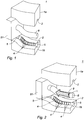
- La
figure 1 représente un moule en position ouverte et un noyau, selon l'invention, - La
figure 2 représente le positionnement sur le noyau d'une nappe tubulaire selon l'invention, - La
figure 3 représente la fermeture du moule, selon l'invention, - La
figure 4 est une vue en transparence d'un moule fermé, avant l'injection d'un matériau élastomère thermoplastique, - La
figure 5 est une vue en transparence d'un moule fermé, lors de l'injection d'un matériau élastomère thermoplastique, - La
figure 6 est une représentation de l'ouverture du moule après injection, - La
figure 7 est une représentation de l'éjection du conduit d'admission d'air moulé, - La
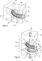
figure 8 est une représentation d'un conduit d'admission d'air selon un premier mode de réalisation de l'invention, - La
figure 9 est une représentation d'un conduit d'admission d'air selon un deuxième mode de réalisation. - L'invention concerne un procédé de fabrication d'un conduit d'admission d'air et d'atténuation des bruits de bouche et des bruits rayonnés destiné à être relié à un moteur à combustion interne.
- Le procédé selon l'invention peut être mis en œuvre avec un moule 1 présenté sur les
figures 1 à 7 . Le moule 1 est destiné à être installé dans une presse à injecter. Selon le mode de réalisation ici présenté, le moule 1 comprend une première coquille la et une deuxième coquille 1b. Les deux coquilles 1a et 1b sont configurées pour être pressées l'une contre l'autre lors de l'injection d'une matière dans le moule, et pour être écartées l'une de l'autre après l'opération d'injection. D'une manière traditionnelle, la première coquille la est mobile et la deuxième coquille 1b est fixe, par rapport à une presse à injecter. Ainsi le moule 1 est mobile entre une position ouverte dans laquelle les deux coquilles 1a et 1b sont écartées l'une de l'autre et une position fermée dans laquelle les deux coquilles 1a et 1b sont pressées l'une contre l'autre. D'une manière classique, le moule 1 peut être réalisé en métal. Chaque coquille la-lb présente une empreinte 2. Selon l'exemple ici présenté, chaque empreinte 2 présente une forme sensiblement hémicylindrique présentant une courbure longitudinale et deux extrémités. Chaque empreinte 2 présente plusieurs rainures 4 et deux demi-alésages 5. Les deux demi-alésages 5 sont positionnés aux extrémités de l'empreinte 2. En condition d'utilisation, les rainures 4 permettent de mouler une ou plusieurs nervures 32 d'un conduit 30. De même, en condition d'utilisation, les deux demi-alésages 5 permettent de mouler des manchons d'extrémité 34-36 du conduit 30. - Selon un premier mode de réalisation, les rainures 4 sont adaptées pour mouler une nervure 32 hélicoïdale.
- Selon un deuxième mode de réalisation, les rainures 4 sont adaptées pour mouler plusieurs nervures 32 formant une grille.
- En outre, selon un mode de réalisation non représenté, chaque empreinte 2 peut aussi présenter des éléments permettant de mouler, par exemple, des systèmes de fixation tels que des pattes de support, et des systèmes d'accroche d'autres éléments tels que des câbles ou d'autres conduits.
- Le procédé selon l'invention utilise aussi un noyau 8 adapté pour coopérer avec le moule 1. D'une manière connue, dans le domaine du moulage par injection, un noyau permet de former une partie creuse d'une pièce ou de réserver une ouverture. Dans le procédé selon l'invention, le noyau 8 permet de réserver la section creuse du conduit 30. Le noyau 8 peut être réalisé en métal. Le noyau 8 est adapté pour être positionné entre les empreintes 2. Selon l'exemple ici présenté, le noyau 8 présente une forme sensiblement cylindrique avec une courbure longitudinale. Selon le mode de réalisation ici présenté, le noyau 8 est fixé à une embase 81 adaptée pour être appuyée contre les deux coquilles 1a et 1b du moule 1 en position fermée.
- Le moule 1 et le noyau 8 permettent de mettre en œuvre le procédé de fabrication d'un conduit d'admission d'air 30 selon l'invention. Outre une étape a de fourniture du moule 1 et une étape b de fourniture du noyau 8, le procédé comprend une étape c de positionnement sur le noyau 8 d'une nappe tubulaire 9. Il est précisé que par nappe tubulaire 9 on entend, une nappe présentant deux bordures jointes pour former sensiblement un cylindre à base circulaire. Les deux bordures jointes de la nappe peuvent être soudées, collées ou cousues. En référence à la
figure 2 la nappe tubulaire 9 est emmanchée sur le noyau 8 selon la direction de la flèche I. La nappe tubulaire 9 peut, par exemple, être réalisée en matériau tissé ou non tissé pouvant comprendre plusieurs composants. La nappe tubulaire 9 peut présenter une porosité comprise entre 200 l/m2/s et 600 l/m2/s sous une perte de charge de 200 Pascals. - Selon une disposition particulière, la nappe tubulaire 9 peut être réalisée à partir d'un matériau non-tissé, produit par aiguilletage, comprenant des fibres de polyester et des fibres bi-composantes. Les fibres bi-composantes peuvent comprendre une âme en polyester et une peau en copolyester.
- Ensuite, le procédé comprend une étape d de positionnement du noyau 8 entre les empreintes 2 du moule 1 en position ouverte. Puis, comme représenté sur la
figure 3 , le moule 1 est fermé selon les directions des flèches II. Lors du passage en position fermée, l'appui de l'embase 81 contre les coquilles 1a et 1b peut servir de référence pour garantir le positionnement correct du noyau 8 entre les empreintes 2. En référence à lafigure 5 , le procédé présente ensuite une étape e d'injection dans chaque rainure 4 et dans chaque demi-alésage 5, de chaque empreinte 2 d'un matériau élastomère thermoplastique, pour surmouler des nervures 32 et des manchons d'extrémité 34 sur la nappe tubulaire 9. Cette étape permet de mouler le conduit 30 en une seule injection. D'une manière particulièrement avantageuse, lors de l'injection dans les rainures 4, le matériau élastomère thermoplastique pénètre localement dans la nappe tubulaire 9, ce qui permet d'assurer la cohésion de la nappe tubulaire 9 avec la, ou chaque nervure 32 surmoulée sur la nappe tubulaire 9. Selon une disposition particulière, le matériau élastomère thermoplastique peut être du type éthylène-propylène-diène monomère mélangé avec du polypropylène. Le surmoulage des nervures 32 sur la nappe tubulaire 9 permet de fabriquer un conduit 30 présentant une surface maximale en nappe tubulaire poreuse, tout en présentant une résistance optimale à la dépression. - En référence à la
figure 6 , le moule 1 est ensuite ouvert selon les directions des flèches III, pour permettre la récupération du conduit 30. Selon une disposition particulière, le procédé peut comprendre une étape f de déchaussement en force du conduit 30 moulé, par de l'air pulsé (figure 7 ), selon la direction de la flèche IV. - Ainsi, le procédé selon l'invention permet de fabriquer le conduit 30 en une seule opération d'injection. Le surmoulage des nervures 32 et des manchons d'extrémité 34 sur la nappe tubulaire 9 permet d'assurer la cohésion du conduit 30. En d'autres termes, le procédé selon l'invention permet de fabriquer le conduit 30 en une seule opération d'injection sans qu'il soit nécessaire d'ajouter des opérations de collage, de clippage ou de reprise des différents constituants du conduit 30.
- L'invention concerne aussi un conduit 30 d'admission d'air et d'atténuation des bruits de bouche et des bruits rayonnés destiné à être relié à un moteur à combustion interne. Le conduit 30 comprend une nappe tubulaire 9 en matériau poreux à l'air sur laquelle sont surmoulées une ou plusieurs nervures 32 en matériau élastomère thermoplastique et deux manchons d'extrémités 34-36 en matériau élastomère thermoplastique.
- La nappe tubulaire 9 peut présenter une porosité comprise entre 200 l/m2/s et 600 l/m2/s. Une telle porosité permet une atténuation optimale des bruits de bouche et des bruits rayonnés.
- Selon un premier mode de réalisation, représenté sur la
figure 8 , le conduit 30 comprend une nervure 32 hélicoïdale. La nervure 32 hélicoïdale peut permettre au conduit 30 d'être flexible. - Selon un deuxième mode de réalisation, représenté sur la
figure 9 , le conduit 30 comprend plusieurs nervures 32 formant une grille. - En condition d'utilisation, un premier manchon 34 est connecté à un moteur à combustion interne et un deuxième manchon 36 est connecté à un circuit d'admission d'air. De plus, la ou les nervures 32 permettent de garantir la résistance du conduit 30 à la dépression provoquée par l'aspiration d'air. La nappe tubulaire 9, en matériau poreux, permet de faire une rupture impédance acoustique ou une adaptation, ce qui permet d'éviter l'excitation de certains modes de conduit. Ainsi la nappe tubulaire 9 permet de réduire les bruits de bouche. De plus, de part la porosité du matériau de la nappe tubulaire 9, la nappe tubulaire permet 9 permet de diffuser une partie de l'énergie acoustique. La présence d'un matériau poreux sur quasiment toute la périphérie du conduit 30 permet de répartir l'énergie rayonnée d'une manière optimale, et ainsi de réduire les bruits rayonnés.
- Bien entendu, l'invention n'est nullement limitée aux modes de réalisation décrits ci-dessus et illustrés par les différentes figures, ces modes de réalisation n'ayant été donnés qu'à titre d'exemples. Des modifications restent possibles, notamment du point de vue de la constitution des divers éléments ou par la substitution d'équivalents techniques, sans pour autant sortir du domaine de l'invention.
Claims (10)
- Procédé de fabrication d'un conduit (30) d'admission d'air et d'atténuation des bruits de bouche et des bruits rayonnés destiné à être relié à un moteur à combustion interne, caractérisé en ce qu'il comprend les étapes de :- (a) : fourniture d'un moule (1) comprenant deux empreintes (2) de moulage, chaque empreinte (2) présentant au moins une rainure (4) adaptée pour mouler une nervure (32) et présentant au moins deux demi-alésages (5) adaptés pour mouler des manchons (34-36) d'extrémité,- (b) : fourniture d'un noyau (8) adapté pour être positionné entre les empreintes (2), pour mouler un conduit (30) d'admission d'air,- (c) : positionnement sur le noyau (8) d'une nappe tubulaire (9) en matériau poreux à l'air,- (d) : positionnement entre les empreintes (2) de moulage du noyau (8) avec la nappe tubulaire (9),- (e) : injection dans la, ou chaque, rainure (4) et dans chaque demi-alésage (5), de chaque empreinte (2) d'un matériau thermoplastique, pour surmouler des nervures (32) et des manchons (34-36) d'extrémité sur la nappe tubulaire (9), afin de former un conduit (30).
- Procédé selon la revendication 1, caractérisé en ce qu'il comprend une étape (f) de déchaussement en force du conduit (30) moulé, par de l'air pulsé.
- Procédé selon l'une des revendications 1 ou 2, caractérisé en ce que l'étape (a) comprend la fourniture de deux empreintes (2) de moulage dans lesquelles les rainures (4) sont adaptées pour mouler une nervure hélicoïdale (32).
- Procédé selon l'une des revendications 1 ou 2, caractérisé en ce que l'étape (a) comprend la fourniture de deux empreintes (2) de moulage dans lesquelles les rainures (4) sont adaptées pour mouler plusieurs nervures (32) formant une grille.
- Procédé selon l'une quelconque des revendications 1 à 4, caractérisé en ce que l'étape (e) comprend l'injection d'un matériau élastomère thermoplastique.
- Conduit (30) d'admission d'air et d'atténuation des bruits de bouche et des bruits rayonnés destiné à être relié à un moteur à combustion interne caractérisé en ce qu'il comprend une nappe tubulaire (9) en matériau poreux à l'air sur laquelle sont surmoulés au moins une nervure (32) en matériau thermoplastique et deux manchons (34-36) d'extrémités en matériau élastomère thermoplastique, un premier manchon (34) étant destiné à être connecté à un moteur à combustion interne et un deuxième manchon (36) étant destiné à être connecté à un circuit d'admission d'air.
- Conduit (30) selon la revendication 6, caractérisé en ce qu'il comprend une nervure hélicoïdale (32).
- Conduit (30) selon la revendication 6, caractérisé en ce qu'il comprend plusieurs nervures (32) formant une grille.
- Conduit (30) selon l'une quelconque des revendications 6 à 8, caractérisé en ce que la nappe tubulaire (9) présente une porosité comprise entre 200 l/m2/s et 600 l/m2/s sous une perte de charge de 200 Pascals.
- Conduit (30) selon l'une quelconque des revendications 6 à 9, caractérisé en ce que le matériau thermoplastique est un matériau élastomère thermoplastique.
Applications Claiming Priority (2)
| Application Number | Priority Date | Filing Date | Title |
|---|---|---|---|
| FR1755189A FR3067280B1 (fr) | 2017-06-09 | 2017-06-09 | Procede de fabrication d’un conduit d’admission d’air |
| PCT/FR2018/051048 WO2018224744A1 (fr) | 2017-06-09 | 2018-04-25 | Procede de fabrication d'un conduit d'admission d'air |
Publications (2)
| Publication Number | Publication Date |
|---|---|
| EP3634712A1 EP3634712A1 (fr) | 2020-04-15 |
| EP3634712B1 true EP3634712B1 (fr) | 2021-04-07 |
Family
ID=59699881
Family Applications (1)
| Application Number | Title | Priority Date | Filing Date |
|---|---|---|---|
| EP18725291.1A Active EP3634712B1 (fr) | 2017-06-09 | 2018-04-25 | Procede de fabrication d'un conduit d'admission d'air |
Country Status (6)
| Country | Link |
|---|---|
| US (1) | US20200240656A1 (fr) |
| EP (1) | EP3634712B1 (fr) |
| JP (1) | JP6990721B2 (fr) |
| ES (1) | ES2878293T3 (fr) |
| FR (1) | FR3067280B1 (fr) |
| WO (1) | WO2018224744A1 (fr) |
Families Citing this family (2)
| Publication number | Priority date | Publication date | Assignee | Title |
|---|---|---|---|---|
| DE102020206045A1 (de) * | 2020-05-13 | 2021-11-18 | Ford Global Technologies, Llc | Verfahren zur Herstellung eines Hohlkörper-Verbundbauteils, sowie Projektil zum Einsatz in einem solchen Verfahren |
| US12194700B2 (en) * | 2023-01-10 | 2025-01-14 | Rohr, Inc. | Forming duct structure with overbraided woven fiber sleeve |
Family Cites Families (10)
| Publication number | Priority date | Publication date | Assignee | Title |
|---|---|---|---|---|
| DE3312231A1 (de) * | 1983-04-05 | 1984-10-11 | Bayer Ag, 5090 Leverkusen | Hohlkoerper aus kunststoffen |
| BR7400072U (pt) | 1994-01-28 | 1994-10-04 | Westaflex Tubos Flexiveis Ltda | Disposições construtivas introduzidas em bubo cilíndrico flexível |
| FR2788833B1 (fr) | 1999-01-22 | 2001-03-16 | Mecaplast Sam | Dispositif de diminution de bruit d'air, procede de fabrication et utilisations d'un tel dispositif |
| WO2005016626A1 (fr) | 2003-08-19 | 2005-02-24 | Tigers Polymer Corporation | Procede de formation d'un conduit en elastomere |
| JP2008063970A (ja) | 2006-09-05 | 2008-03-21 | Toyota Boshoku Corp | 吸気ダクト |
| DE102007060525A1 (de) * | 2007-12-13 | 2009-06-18 | Aksys Gmbh | Schalldämpfungs-Luftführungskanal und Verfahren zur Herstellung eines Schalldämpfungs-Luftführungskanals |
| JP5084618B2 (ja) | 2008-06-03 | 2012-11-28 | 株式会社Roki | 吸気ダクト |
| JP5530880B2 (ja) * | 2010-09-28 | 2014-06-25 | 東海ゴム工業株式会社 | 管体用防音カバーおよびカバー付き管体 |
| ES2635425T3 (es) * | 2011-09-05 | 2017-10-03 | Roki Co., Ltd. | Conducto de entrada de aire |
| JP6449095B2 (ja) * | 2015-05-01 | 2019-01-09 | タイガースポリマー株式会社 | 通気ダクト |
-
2017
- 2017-06-09 FR FR1755189A patent/FR3067280B1/fr not_active Expired - Fee Related
-
2018
- 2018-04-25 EP EP18725291.1A patent/EP3634712B1/fr active Active
- 2018-04-25 ES ES18725291T patent/ES2878293T3/es active Active
- 2018-04-25 US US16/620,279 patent/US20200240656A1/en not_active Abandoned
- 2018-04-25 JP JP2019567325A patent/JP6990721B2/ja not_active Expired - Fee Related
- 2018-04-25 WO PCT/FR2018/051048 patent/WO2018224744A1/fr not_active Ceased
Also Published As
| Publication number | Publication date |
|---|---|
| EP3634712A1 (fr) | 2020-04-15 |
| US20200240656A1 (en) | 2020-07-30 |
| ES2878293T3 (es) | 2021-11-18 |
| FR3067280A1 (fr) | 2018-12-14 |
| JP6990721B2 (ja) | 2022-01-12 |
| WO2018224744A1 (fr) | 2018-12-13 |
| JP2020522408A (ja) | 2020-07-30 |
| FR3067280B1 (fr) | 2019-07-19 |
Similar Documents
| Publication | Publication Date | Title |
|---|---|---|
| EP3916717B1 (fr) | Structure alvéolaire d'insonorisation incluant un diaphragme muni d'un tube configuré pour traiter différentes fréquences acoustiques, procédé de fabrication d'une telle structure alvéolaire d'insonorisation, et outil associé | |
| FR3026122B1 (fr) | Panneau de traitement acoustique | |
| FR3055662A1 (fr) | Structure interne d'un conduit d'ejection primaire d'une turbomachine comprenant une structure absorbante de sons basses frequences | |
| WO2021004735A1 (fr) | Revêtement insonorisant comportant une structure alvéolaire | |
| WO2002093978A2 (fr) | Emetteur de son et haut-parleur | |
| EP3634712B1 (fr) | Procede de fabrication d'un conduit d'admission d'air | |
| EP1956281B1 (fr) | Dispositif d'atténuation des bruits pour circuit d'admission de fluide gazeux | |
| FR3111002A1 (fr) | Procédé de fabrication d'une structure alvéolaire d’insonorisation incluant un diaphragme, et structure alvéolaire d’insonorisation obtenue | |
| EP3674530A1 (fr) | Procédé de fabrication d'une structure d'absorption acoustique comprenant un panneau alvéolaire intégrant des éléments acoustiques et structure d' absorption acoustique obtenue à partir dudit procédé | |
| EP2256330B1 (fr) | Dispositif d'atténuation acoustique pour ligne d'admission d'un moteur thermique, et ligne d'admission l'incorporant. | |
| FR2914958A1 (fr) | Conduit pour la circulation d'un fluide gazeux, notamment soumis a une action d'aspiration | |
| EP3303815B1 (fr) | Dispositif d'atténuation des bruits de bouche et des bruits rayonnés | |
| WO2016071623A1 (fr) | Conduit intégrant un dispositif d'atténuation acoustique | |
| EP2435685B1 (fr) | Turbomoteur comportant un cone de guidage des gaz d'echappement avec un attenuateur sonore | |
| EP0827567B1 (fr) | Collecteur d'admission a tubes d'air anneles, pour moteur a combustion interne | |
| EP3409937A1 (fr) | Conduit d'admission d'air et d'attenuation des bruits | |
| EP3636909B1 (fr) | Dispositif d'atténuation acoustique pour une ligne d'admission d'un moteur à combustion thermique équipée d'un turbocompresseur | |
| EP1843021A2 (fr) | Cache moteur pour véhicule automobile | |
| EP4063703B1 (fr) | Conduit de circulation d'un fluide gazeux comprenant un revêtement absorbant acoustique | |
| EP4685787A1 (fr) | Structure d'absorption acoustique comprenant un système de cloisonnement pourvu d'au moins un pied | |
| EP4693275A1 (fr) | Structure d absorption acoustique comportant une structure alvéolaire ainsi qu au moins une enceinte de cloisonnement positionnée dans une cellule de la structure alvéolaire | |
| FR2890417A1 (fr) | Silencieux ameliore pour compresseur de fluides, notamment pour compresseur a air pour suspensions de vehicules automobiles | |
| FR2835954A1 (fr) | Procede d'insonorisation, piece insonorisante et ensemble correspondant | |
| FR2681752A3 (en) | Microphone probe including an attenuator material | |
| FR2894283A1 (fr) | Silencieux d'echappement |
Legal Events
| Date | Code | Title | Description |
|---|---|---|---|
| STAA | Information on the status of an ep patent application or granted ep patent |
Free format text: STATUS: UNKNOWN |
|
| STAA | Information on the status of an ep patent application or granted ep patent |
Free format text: STATUS: THE INTERNATIONAL PUBLICATION HAS BEEN MADE |
|
| PUAI | Public reference made under article 153(3) epc to a published international application that has entered the european phase |
Free format text: ORIGINAL CODE: 0009012 |
|
| STAA | Information on the status of an ep patent application or granted ep patent |
Free format text: STATUS: REQUEST FOR EXAMINATION WAS MADE |
|
| 17P | Request for examination filed |
Effective date: 20191021 |
|
| AK | Designated contracting states |
Kind code of ref document: A1 Designated state(s): AL AT BE BG CH CY CZ DE DK EE ES FI FR GB GR HR HU IE IS IT LI LT LU LV MC MK MT NL NO PL PT RO RS SE SI SK SM TR |
|
| AX | Request for extension of the european patent |
Extension state: BA ME |
|
| DAV | Request for validation of the european patent (deleted) | ||
| DAX | Request for extension of the european patent (deleted) | ||
| GRAP | Despatch of communication of intention to grant a patent |
Free format text: ORIGINAL CODE: EPIDOSNIGR1 |
|
| STAA | Information on the status of an ep patent application or granted ep patent |
Free format text: STATUS: GRANT OF PATENT IS INTENDED |
|
| INTG | Intention to grant announced |
Effective date: 20210128 |
|
| GRAS | Grant fee paid |
Free format text: ORIGINAL CODE: EPIDOSNIGR3 |
|
| GRAA | (expected) grant |
Free format text: ORIGINAL CODE: 0009210 |
|
| STAA | Information on the status of an ep patent application or granted ep patent |
Free format text: STATUS: THE PATENT HAS BEEN GRANTED |
|
| AK | Designated contracting states |
Kind code of ref document: B1 Designated state(s): AL AT BE BG CH CY CZ DE DK EE ES FI FR GB GR HR HU IE IS IT LI LT LU LV MC MK MT NL NO PL PT RO RS SE SI SK SM TR |
|
| REG | Reference to a national code |
Ref country code: GB Ref legal event code: FG4D Free format text: NOT ENGLISH |
|
| REG | Reference to a national code |
Ref country code: AT Ref legal event code: REF Ref document number: 1379094 Country of ref document: AT Kind code of ref document: T Effective date: 20210415 Ref country code: CH Ref legal event code: EP |
|
| REG | Reference to a national code |
Ref country code: DE Ref legal event code: R096 Ref document number: 602018015237 Country of ref document: DE |
|
| REG | Reference to a national code |
Ref country code: IE Ref legal event code: FG4D Free format text: LANGUAGE OF EP DOCUMENT: FRENCH |
|
| REG | Reference to a national code |
Ref country code: LT Ref legal event code: MG9D |
|
| REG | Reference to a national code |
Ref country code: NL Ref legal event code: MP Effective date: 20210407 Ref country code: AT Ref legal event code: MK05 Ref document number: 1379094 Country of ref document: AT Kind code of ref document: T Effective date: 20210407 |
|
| PG25 | Lapsed in a contracting state [announced via postgrant information from national office to epo] |
Ref country code: HR Free format text: LAPSE BECAUSE OF FAILURE TO SUBMIT A TRANSLATION OF THE DESCRIPTION OR TO PAY THE FEE WITHIN THE PRESCRIBED TIME-LIMIT Effective date: 20210407 Ref country code: LT Free format text: LAPSE BECAUSE OF FAILURE TO SUBMIT A TRANSLATION OF THE DESCRIPTION OR TO PAY THE FEE WITHIN THE PRESCRIBED TIME-LIMIT Effective date: 20210407 Ref country code: FI Free format text: LAPSE BECAUSE OF FAILURE TO SUBMIT A TRANSLATION OF THE DESCRIPTION OR TO PAY THE FEE WITHIN THE PRESCRIBED TIME-LIMIT Effective date: 20210407 Ref country code: NL Free format text: LAPSE BECAUSE OF FAILURE TO SUBMIT A TRANSLATION OF THE DESCRIPTION OR TO PAY THE FEE WITHIN THE PRESCRIBED TIME-LIMIT Effective date: 20210407 Ref country code: AT Free format text: LAPSE BECAUSE OF FAILURE TO SUBMIT A TRANSLATION OF THE DESCRIPTION OR TO PAY THE FEE WITHIN THE PRESCRIBED TIME-LIMIT Effective date: 20210407 Ref country code: BG Free format text: LAPSE BECAUSE OF FAILURE TO SUBMIT A TRANSLATION OF THE DESCRIPTION OR TO PAY THE FEE WITHIN THE PRESCRIBED TIME-LIMIT Effective date: 20210707 |
|
| REG | Reference to a national code |
Ref country code: ES Ref legal event code: FG2A Ref document number: 2878293 Country of ref document: ES Kind code of ref document: T3 Effective date: 20211118 |
|
| PG25 | Lapsed in a contracting state [announced via postgrant information from national office to epo] |
Ref country code: GR Free format text: LAPSE BECAUSE OF FAILURE TO SUBMIT A TRANSLATION OF THE DESCRIPTION OR TO PAY THE FEE WITHIN THE PRESCRIBED TIME-LIMIT Effective date: 20210708 Ref country code: IS Free format text: LAPSE BECAUSE OF FAILURE TO SUBMIT A TRANSLATION OF THE DESCRIPTION OR TO PAY THE FEE WITHIN THE PRESCRIBED TIME-LIMIT Effective date: 20210807 Ref country code: SE Free format text: LAPSE BECAUSE OF FAILURE TO SUBMIT A TRANSLATION OF THE DESCRIPTION OR TO PAY THE FEE WITHIN THE PRESCRIBED TIME-LIMIT Effective date: 20210407 Ref country code: RS Free format text: LAPSE BECAUSE OF FAILURE TO SUBMIT A TRANSLATION OF THE DESCRIPTION OR TO PAY THE FEE WITHIN THE PRESCRIBED TIME-LIMIT Effective date: 20210407 Ref country code: PT Free format text: LAPSE BECAUSE OF FAILURE TO SUBMIT A TRANSLATION OF THE DESCRIPTION OR TO PAY THE FEE WITHIN THE PRESCRIBED TIME-LIMIT Effective date: 20210809 Ref country code: LV Free format text: LAPSE BECAUSE OF FAILURE TO SUBMIT A TRANSLATION OF THE DESCRIPTION OR TO PAY THE FEE WITHIN THE PRESCRIBED TIME-LIMIT Effective date: 20210407 Ref country code: NO Free format text: LAPSE BECAUSE OF FAILURE TO SUBMIT A TRANSLATION OF THE DESCRIPTION OR TO PAY THE FEE WITHIN THE PRESCRIBED TIME-LIMIT Effective date: 20210707 Ref country code: PL Free format text: LAPSE BECAUSE OF FAILURE TO SUBMIT A TRANSLATION OF THE DESCRIPTION OR TO PAY THE FEE WITHIN THE PRESCRIBED TIME-LIMIT Effective date: 20210407 |
|
| PG25 | Lapsed in a contracting state [announced via postgrant information from national office to epo] |
Ref country code: LU Free format text: LAPSE BECAUSE OF NON-PAYMENT OF DUE FEES Effective date: 20210425 |
|
| REG | Reference to a national code |
Ref country code: DE Ref legal event code: R097 Ref document number: 602018015237 Country of ref document: DE |
|
| REG | Reference to a national code |
Ref country code: BE Ref legal event code: MM Effective date: 20210430 |
|
| PG25 | Lapsed in a contracting state [announced via postgrant information from national office to epo] |
Ref country code: SK Free format text: LAPSE BECAUSE OF FAILURE TO SUBMIT A TRANSLATION OF THE DESCRIPTION OR TO PAY THE FEE WITHIN THE PRESCRIBED TIME-LIMIT Effective date: 20210407 Ref country code: EE Free format text: LAPSE BECAUSE OF FAILURE TO SUBMIT A TRANSLATION OF THE DESCRIPTION OR TO PAY THE FEE WITHIN THE PRESCRIBED TIME-LIMIT Effective date: 20210407 Ref country code: SM Free format text: LAPSE BECAUSE OF FAILURE TO SUBMIT A TRANSLATION OF THE DESCRIPTION OR TO PAY THE FEE WITHIN THE PRESCRIBED TIME-LIMIT Effective date: 20210407 Ref country code: RO Free format text: LAPSE BECAUSE OF FAILURE TO SUBMIT A TRANSLATION OF THE DESCRIPTION OR TO PAY THE FEE WITHIN THE PRESCRIBED TIME-LIMIT Effective date: 20210407 Ref country code: DK Free format text: LAPSE BECAUSE OF FAILURE TO SUBMIT A TRANSLATION OF THE DESCRIPTION OR TO PAY THE FEE WITHIN THE PRESCRIBED TIME-LIMIT Effective date: 20210407 Ref country code: CH Free format text: LAPSE BECAUSE OF NON-PAYMENT OF DUE FEES Effective date: 20210430 Ref country code: CZ Free format text: LAPSE BECAUSE OF FAILURE TO SUBMIT A TRANSLATION OF THE DESCRIPTION OR TO PAY THE FEE WITHIN THE PRESCRIBED TIME-LIMIT Effective date: 20210407 Ref country code: MC Free format text: LAPSE BECAUSE OF FAILURE TO SUBMIT A TRANSLATION OF THE DESCRIPTION OR TO PAY THE FEE WITHIN THE PRESCRIBED TIME-LIMIT Effective date: 20210407 Ref country code: LI Free format text: LAPSE BECAUSE OF NON-PAYMENT OF DUE FEES Effective date: 20210430 |
|
| PLBE | No opposition filed within time limit |
Free format text: ORIGINAL CODE: 0009261 |
|
| STAA | Information on the status of an ep patent application or granted ep patent |
Free format text: STATUS: NO OPPOSITION FILED WITHIN TIME LIMIT |
|
| 26N | No opposition filed |
Effective date: 20220110 |
|
| PG25 | Lapsed in a contracting state [announced via postgrant information from national office to epo] |
Ref country code: IE Free format text: LAPSE BECAUSE OF NON-PAYMENT OF DUE FEES Effective date: 20210425 |
|
| PG25 | Lapsed in a contracting state [announced via postgrant information from national office to epo] |
Ref country code: IS Free format text: LAPSE BECAUSE OF FAILURE TO SUBMIT A TRANSLATION OF THE DESCRIPTION OR TO PAY THE FEE WITHIN THE PRESCRIBED TIME-LIMIT Effective date: 20210807 Ref country code: AL Free format text: LAPSE BECAUSE OF FAILURE TO SUBMIT A TRANSLATION OF THE DESCRIPTION OR TO PAY THE FEE WITHIN THE PRESCRIBED TIME-LIMIT Effective date: 20210407 |
|
| PG25 | Lapsed in a contracting state [announced via postgrant information from national office to epo] |
Ref country code: IT Free format text: LAPSE BECAUSE OF FAILURE TO SUBMIT A TRANSLATION OF THE DESCRIPTION OR TO PAY THE FEE WITHIN THE PRESCRIBED TIME-LIMIT Effective date: 20210407 Ref country code: BE Free format text: LAPSE BECAUSE OF NON-PAYMENT OF DUE FEES Effective date: 20210430 |
|
| GBPC | Gb: european patent ceased through non-payment of renewal fee |
Effective date: 20220425 |
|
| PG25 | Lapsed in a contracting state [announced via postgrant information from national office to epo] |
Ref country code: GB Free format text: LAPSE BECAUSE OF NON-PAYMENT OF DUE FEES Effective date: 20220425 |
|
| PG25 | Lapsed in a contracting state [announced via postgrant information from national office to epo] |
Ref country code: CY Free format text: LAPSE BECAUSE OF FAILURE TO SUBMIT A TRANSLATION OF THE DESCRIPTION OR TO PAY THE FEE WITHIN THE PRESCRIBED TIME-LIMIT Effective date: 20210407 |
|
| PG25 | Lapsed in a contracting state [announced via postgrant information from national office to epo] |
Ref country code: HU Free format text: LAPSE BECAUSE OF FAILURE TO SUBMIT A TRANSLATION OF THE DESCRIPTION OR TO PAY THE FEE WITHIN THE PRESCRIBED TIME-LIMIT; INVALID AB INITIO Effective date: 20180425 |
|
| PGFP | Annual fee paid to national office [announced via postgrant information from national office to epo] |
Ref country code: ES Payment date: 20230504 Year of fee payment: 6 Ref country code: DE Payment date: 20230418 Year of fee payment: 6 |
|
| PG25 | Lapsed in a contracting state [announced via postgrant information from national office to epo] |
Ref country code: MK Free format text: LAPSE BECAUSE OF FAILURE TO SUBMIT A TRANSLATION OF THE DESCRIPTION OR TO PAY THE FEE WITHIN THE PRESCRIBED TIME-LIMIT Effective date: 20210407 |
|
| PG25 | Lapsed in a contracting state [announced via postgrant information from national office to epo] |
Ref country code: MT Free format text: LAPSE BECAUSE OF FAILURE TO SUBMIT A TRANSLATION OF THE DESCRIPTION OR TO PAY THE FEE WITHIN THE PRESCRIBED TIME-LIMIT Effective date: 20210407 |
|
| REG | Reference to a national code |
Ref country code: DE Ref legal event code: R119 Ref document number: 602018015237 Country of ref document: DE |
|
| PG25 | Lapsed in a contracting state [announced via postgrant information from national office to epo] |
Ref country code: DE Free format text: LAPSE BECAUSE OF NON-PAYMENT OF DUE FEES Effective date: 20241105 |
|
| PG25 | Lapsed in a contracting state [announced via postgrant information from national office to epo] |
Ref country code: DE Free format text: LAPSE BECAUSE OF NON-PAYMENT OF DUE FEES Effective date: 20241105 |
|
| REG | Reference to a national code |
Ref country code: ES Ref legal event code: FD2A Effective date: 20250530 |
|
| PG25 | Lapsed in a contracting state [announced via postgrant information from national office to epo] |
Ref country code: ES Free format text: LAPSE BECAUSE OF NON-PAYMENT OF DUE FEES Effective date: 20240426 |
|
| PG25 | Lapsed in a contracting state [announced via postgrant information from national office to epo] |
Ref country code: TR Free format text: LAPSE BECAUSE OF FAILURE TO SUBMIT A TRANSLATION OF THE DESCRIPTION OR TO PAY THE FEE WITHIN THE PRESCRIBED TIME-LIMIT Effective date: 20210407 |
|
| PGFP | Annual fee paid to national office [announced via postgrant information from national office to epo] |
Ref country code: FR Payment date: 20260330 Year of fee payment: 9 |