EP3916717B1 - Structure alvéolaire d'insonorisation incluant un diaphragme muni d'un tube configuré pour traiter différentes fréquences acoustiques, procédé de fabrication d'une telle structure alvéolaire d'insonorisation, et outil associé - Google Patents
Structure alvéolaire d'insonorisation incluant un diaphragme muni d'un tube configuré pour traiter différentes fréquences acoustiques, procédé de fabrication d'une telle structure alvéolaire d'insonorisation, et outil associé Download PDFInfo
- Publication number
- EP3916717B1 EP3916717B1 EP21173044.5A EP21173044A EP3916717B1 EP 3916717 B1 EP3916717 B1 EP 3916717B1 EP 21173044 A EP21173044 A EP 21173044A EP 3916717 B1 EP3916717 B1 EP 3916717B1
- Authority
- EP
- European Patent Office
- Prior art keywords
- diaphragm
- cell
- membrane
- acoustic
- tube
- Prior art date
- Legal status (The legal status is an assumption and is not a legal conclusion. Google has not performed a legal analysis and makes no representation as to the accuracy of the status listed.)
- Active
Links
- 238000000034 method Methods 0.000 title claims description 25
- 238000004519 manufacturing process Methods 0.000 title claims description 6
- 210000004027 cell Anatomy 0.000 claims description 137
- 239000012528 membrane Substances 0.000 claims description 70
- 238000003780 insertion Methods 0.000 claims description 54
- 230000037431 insertion Effects 0.000 claims description 54
- 210000003850 cellular structure Anatomy 0.000 claims description 32
- 230000001413 cellular effect Effects 0.000 claims description 9
- 238000003825 pressing Methods 0.000 claims description 3
- 210000000188 diaphragm Anatomy 0.000 description 119
- 239000000853 adhesive Substances 0.000 description 11
- 230000001070 adhesive effect Effects 0.000 description 11
- 238000011282 treatment Methods 0.000 description 7
- 210000003456 pulmonary alveoli Anatomy 0.000 description 5
- 229920005989 resin Polymers 0.000 description 5
- 239000011347 resin Substances 0.000 description 5
- 241001080024 Telles Species 0.000 description 4
- 239000002131 composite material Substances 0.000 description 4
- 235000021183 entrée Nutrition 0.000 description 4
- 238000002347 injection Methods 0.000 description 4
- 239000007924 injection Substances 0.000 description 4
- 239000002184 metal Substances 0.000 description 4
- 230000000694 effects Effects 0.000 description 3
- 239000000463 material Substances 0.000 description 3
- 229920001169 thermoplastic Polymers 0.000 description 3
- 239000004416 thermosoftening plastic Substances 0.000 description 3
- 230000002238 attenuated effect Effects 0.000 description 2
- 238000004891 communication Methods 0.000 description 2
- 229920001971 elastomer Polymers 0.000 description 2
- 239000000806 elastomer Substances 0.000 description 2
- 239000003822 epoxy resin Substances 0.000 description 2
- 238000010438 heat treatment Methods 0.000 description 2
- 239000000123 paper Substances 0.000 description 2
- 229920000647 polyepoxide Polymers 0.000 description 2
- 230000003068 static effect Effects 0.000 description 2
- 229920002994 synthetic fiber Polymers 0.000 description 2
- 239000012815 thermoplastic material Substances 0.000 description 2
- 238000003466 welding Methods 0.000 description 2
- 241000271566 Aves Species 0.000 description 1
- 241000287107 Passer Species 0.000 description 1
- 238000009825 accumulation Methods 0.000 description 1
- 230000006978 adaptation Effects 0.000 description 1
- 230000000712 assembly Effects 0.000 description 1
- 238000000429 assembly Methods 0.000 description 1
- 230000004888 barrier function Effects 0.000 description 1
- 230000015572 biosynthetic process Effects 0.000 description 1
- 230000006835 compression Effects 0.000 description 1
- 238000007906 compression Methods 0.000 description 1
- 238000010411 cooking Methods 0.000 description 1
- 238000013016 damping Methods 0.000 description 1
- 230000001419 dependent effect Effects 0.000 description 1
- 239000012895 dilution Substances 0.000 description 1
- 238000010790 dilution Methods 0.000 description 1
- 238000007598 dipping method Methods 0.000 description 1
- 239000000835 fiber Substances 0.000 description 1
- 239000011159 matrix material Substances 0.000 description 1
- VAOCPAMSLUNLGC-UHFFFAOYSA-N metronidazole Chemical compound CC1=NC=C([N+]([O-])=O)N1CCO VAOCPAMSLUNLGC-UHFFFAOYSA-N 0.000 description 1
- 230000035515 penetration Effects 0.000 description 1
- 230000002093 peripheral effect Effects 0.000 description 1
- 239000004033 plastic Substances 0.000 description 1
- 229920003023 plastic Polymers 0.000 description 1
- 229920001296 polysiloxane Polymers 0.000 description 1
- 230000035939 shock Effects 0.000 description 1
- 238000004513 sizing Methods 0.000 description 1
- 239000000243 solution Substances 0.000 description 1
- 238000001228 spectrum Methods 0.000 description 1
- 238000005507 spraying Methods 0.000 description 1
- 230000035882 stress Effects 0.000 description 1
- 230000008646 thermal stress Effects 0.000 description 1
- 238000011144 upstream manufacturing Methods 0.000 description 1
- 238000009941 weaving Methods 0.000 description 1
Images


Classifications
-
- G—PHYSICS
- G10—MUSICAL INSTRUMENTS; ACOUSTICS
- G10K—SOUND-PRODUCING DEVICES; METHODS OR DEVICES FOR PROTECTING AGAINST, OR FOR DAMPING, NOISE OR OTHER ACOUSTIC WAVES IN GENERAL; ACOUSTICS NOT OTHERWISE PROVIDED FOR
- G10K11/00—Methods or devices for transmitting, conducting or directing sound in general; Methods or devices for protecting against, or for damping, noise or other acoustic waves in general
- G10K11/16—Methods or devices for protecting against, or for damping, noise or other acoustic waves in general
- G10K11/162—Selection of materials
- G10K11/168—Plural layers of different materials, e.g. sandwiches
-
- G—PHYSICS
- G10—MUSICAL INSTRUMENTS; ACOUSTICS
- G10K—SOUND-PRODUCING DEVICES; METHODS OR DEVICES FOR PROTECTING AGAINST, OR FOR DAMPING, NOISE OR OTHER ACOUSTIC WAVES IN GENERAL; ACOUSTICS NOT OTHERWISE PROVIDED FOR
- G10K11/00—Methods or devices for transmitting, conducting or directing sound in general; Methods or devices for protecting against, or for damping, noise or other acoustic waves in general
- G10K11/16—Methods or devices for protecting against, or for damping, noise or other acoustic waves in general
- G10K11/172—Methods or devices for protecting against, or for damping, noise or other acoustic waves in general using resonance effects
-
- B—PERFORMING OPERATIONS; TRANSPORTING
- B64—AIRCRAFT; AVIATION; COSMONAUTICS
- B64D—EQUIPMENT FOR FITTING IN OR TO AIRCRAFT; FLIGHT SUITS; PARACHUTES; ARRANGEMENT OR MOUNTING OF POWER PLANTS OR PROPULSION TRANSMISSIONS IN AIRCRAFT
- B64D33/00—Arrangements in aircraft of power plant parts or auxiliaries not otherwise provided for
- B64D33/02—Arrangements in aircraft of power plant parts or auxiliaries not otherwise provided for of combustion air intakes
-
- B—PERFORMING OPERATIONS; TRANSPORTING
- B32—LAYERED PRODUCTS
- B32B—LAYERED PRODUCTS, i.e. PRODUCTS BUILT-UP OF STRATA OF FLAT OR NON-FLAT, e.g. CELLULAR OR HONEYCOMB, FORM
- B32B1/00—Layered products having a non-planar shape
-
- B—PERFORMING OPERATIONS; TRANSPORTING
- B32—LAYERED PRODUCTS
- B32B—LAYERED PRODUCTS, i.e. PRODUCTS BUILT-UP OF STRATA OF FLAT OR NON-FLAT, e.g. CELLULAR OR HONEYCOMB, FORM
- B32B3/00—Layered products comprising a layer with external or internal discontinuities or unevennesses, or a layer of non-planar shape; Layered products comprising a layer having particular features of form
- B32B3/02—Layered products comprising a layer with external or internal discontinuities or unevennesses, or a layer of non-planar shape; Layered products comprising a layer having particular features of form characterised by features of form at particular places, e.g. in edge regions
- B32B3/06—Layered products comprising a layer with external or internal discontinuities or unevennesses, or a layer of non-planar shape; Layered products comprising a layer having particular features of form characterised by features of form at particular places, e.g. in edge regions for securing layers together; for attaching the product to another member, e.g. to a support, or to another product, e.g. groove/tongue, interlocking
-
- B—PERFORMING OPERATIONS; TRANSPORTING
- B32—LAYERED PRODUCTS
- B32B—LAYERED PRODUCTS, i.e. PRODUCTS BUILT-UP OF STRATA OF FLAT OR NON-FLAT, e.g. CELLULAR OR HONEYCOMB, FORM
- B32B3/00—Layered products comprising a layer with external or internal discontinuities or unevennesses, or a layer of non-planar shape; Layered products comprising a layer having particular features of form
- B32B3/02—Layered products comprising a layer with external or internal discontinuities or unevennesses, or a layer of non-planar shape; Layered products comprising a layer having particular features of form characterised by features of form at particular places, e.g. in edge regions
- B32B3/08—Layered products comprising a layer with external or internal discontinuities or unevennesses, or a layer of non-planar shape; Layered products comprising a layer having particular features of form characterised by features of form at particular places, e.g. in edge regions characterised by added members at particular parts
-
- B—PERFORMING OPERATIONS; TRANSPORTING
- B32—LAYERED PRODUCTS
- B32B—LAYERED PRODUCTS, i.e. PRODUCTS BUILT-UP OF STRATA OF FLAT OR NON-FLAT, e.g. CELLULAR OR HONEYCOMB, FORM
- B32B3/00—Layered products comprising a layer with external or internal discontinuities or unevennesses, or a layer of non-planar shape; Layered products comprising a layer having particular features of form
- B32B3/10—Layered products comprising a layer with external or internal discontinuities or unevennesses, or a layer of non-planar shape; Layered products comprising a layer having particular features of form characterised by a discontinuous layer, i.e. formed of separate pieces of material
- B32B3/12—Layered products comprising a layer with external or internal discontinuities or unevennesses, or a layer of non-planar shape; Layered products comprising a layer having particular features of form characterised by a discontinuous layer, i.e. formed of separate pieces of material characterised by a layer of regularly- arranged cells, e.g. a honeycomb structure
-
- B—PERFORMING OPERATIONS; TRANSPORTING
- B32—LAYERED PRODUCTS
- B32B—LAYERED PRODUCTS, i.e. PRODUCTS BUILT-UP OF STRATA OF FLAT OR NON-FLAT, e.g. CELLULAR OR HONEYCOMB, FORM
- B32B3/00—Layered products comprising a layer with external or internal discontinuities or unevennesses, or a layer of non-planar shape; Layered products comprising a layer having particular features of form
- B32B3/26—Layered products comprising a layer with external or internal discontinuities or unevennesses, or a layer of non-planar shape; Layered products comprising a layer having particular features of form characterised by a particular shape of the outline of the cross-section of a continuous layer; characterised by a layer with cavities or internal voids ; characterised by an apertured layer
- B32B3/266—Layered products comprising a layer with external or internal discontinuities or unevennesses, or a layer of non-planar shape; Layered products comprising a layer having particular features of form characterised by a particular shape of the outline of the cross-section of a continuous layer; characterised by a layer with cavities or internal voids ; characterised by an apertured layer characterised by an apertured layer, the apertures going through the whole thickness of the layer, e.g. expanded metal, perforated layer, slit layer regular cells B32B3/12
-
- B—PERFORMING OPERATIONS; TRANSPORTING
- B32—LAYERED PRODUCTS
- B32B—LAYERED PRODUCTS, i.e. PRODUCTS BUILT-UP OF STRATA OF FLAT OR NON-FLAT, e.g. CELLULAR OR HONEYCOMB, FORM
- B32B3/00—Layered products comprising a layer with external or internal discontinuities or unevennesses, or a layer of non-planar shape; Layered products comprising a layer having particular features of form
- B32B3/26—Layered products comprising a layer with external or internal discontinuities or unevennesses, or a layer of non-planar shape; Layered products comprising a layer having particular features of form characterised by a particular shape of the outline of the cross-section of a continuous layer; characterised by a layer with cavities or internal voids ; characterised by an apertured layer
- B32B3/28—Layered products comprising a layer with external or internal discontinuities or unevennesses, or a layer of non-planar shape; Layered products comprising a layer having particular features of form characterised by a particular shape of the outline of the cross-section of a continuous layer; characterised by a layer with cavities or internal voids ; characterised by an apertured layer characterised by a layer comprising a deformed thin sheet, i.e. the layer having its entire thickness deformed out of the plane, e.g. corrugated, crumpled
-
- B—PERFORMING OPERATIONS; TRANSPORTING
- B32—LAYERED PRODUCTS
- B32B—LAYERED PRODUCTS, i.e. PRODUCTS BUILT-UP OF STRATA OF FLAT OR NON-FLAT, e.g. CELLULAR OR HONEYCOMB, FORM
- B32B5/00—Layered products characterised by the non- homogeneity or physical structure, i.e. comprising a fibrous, filamentary, particulate or foam layer; Layered products characterised by having a layer differing constitutionally or physically in different parts
- B32B5/02—Layered products characterised by the non- homogeneity or physical structure, i.e. comprising a fibrous, filamentary, particulate or foam layer; Layered products characterised by having a layer differing constitutionally or physically in different parts characterised by structural features of a fibrous or filamentary layer
- B32B5/024—Woven fabric
-
- B—PERFORMING OPERATIONS; TRANSPORTING
- B64—AIRCRAFT; AVIATION; COSMONAUTICS
- B64C—AEROPLANES; HELICOPTERS
- B64C1/00—Fuselages; Constructional features common to fuselages, wings, stabilising surfaces or the like
- B64C1/40—Sound or heat insulation, e.g. using insulation blankets
-
- B—PERFORMING OPERATIONS; TRANSPORTING
- B64—AIRCRAFT; AVIATION; COSMONAUTICS
- B64D—EQUIPMENT FOR FITTING IN OR TO AIRCRAFT; FLIGHT SUITS; PARACHUTES; ARRANGEMENT OR MOUNTING OF POWER PLANTS OR PROPULSION TRANSMISSIONS IN AIRCRAFT
- B64D29/00—Power-plant nacelles, fairings, or cowlings
-
- B—PERFORMING OPERATIONS; TRANSPORTING
- B64—AIRCRAFT; AVIATION; COSMONAUTICS
- B64D—EQUIPMENT FOR FITTING IN OR TO AIRCRAFT; FLIGHT SUITS; PARACHUTES; ARRANGEMENT OR MOUNTING OF POWER PLANTS OR PROPULSION TRANSMISSIONS IN AIRCRAFT
- B64D29/00—Power-plant nacelles, fairings, or cowlings
- B64D29/02—Power-plant nacelles, fairings, or cowlings associated with wings
-
- B—PERFORMING OPERATIONS; TRANSPORTING
- B32—LAYERED PRODUCTS
- B32B—LAYERED PRODUCTS, i.e. PRODUCTS BUILT-UP OF STRATA OF FLAT OR NON-FLAT, e.g. CELLULAR OR HONEYCOMB, FORM
- B32B2250/00—Layers arrangement
- B32B2250/03—3 layers
-
- B—PERFORMING OPERATIONS; TRANSPORTING
- B32—LAYERED PRODUCTS
- B32B—LAYERED PRODUCTS, i.e. PRODUCTS BUILT-UP OF STRATA OF FLAT OR NON-FLAT, e.g. CELLULAR OR HONEYCOMB, FORM
- B32B2250/00—Layers arrangement
- B32B2250/44—Number of layers variable across the laminate
-
- B—PERFORMING OPERATIONS; TRANSPORTING
- B32—LAYERED PRODUCTS
- B32B—LAYERED PRODUCTS, i.e. PRODUCTS BUILT-UP OF STRATA OF FLAT OR NON-FLAT, e.g. CELLULAR OR HONEYCOMB, FORM
- B32B2262/00—Composition or structural features of fibres which form a fibrous or filamentary layer or are present as additives
- B32B2262/10—Inorganic fibres
- B32B2262/103—Metal fibres
-
- B—PERFORMING OPERATIONS; TRANSPORTING
- B32—LAYERED PRODUCTS
- B32B—LAYERED PRODUCTS, i.e. PRODUCTS BUILT-UP OF STRATA OF FLAT OR NON-FLAT, e.g. CELLULAR OR HONEYCOMB, FORM
- B32B2307/00—Properties of the layers or laminate
- B32B2307/10—Properties of the layers or laminate having particular acoustical properties
- B32B2307/102—Insulating
-
- B—PERFORMING OPERATIONS; TRANSPORTING
- B32—LAYERED PRODUCTS
- B32B—LAYERED PRODUCTS, i.e. PRODUCTS BUILT-UP OF STRATA OF FLAT OR NON-FLAT, e.g. CELLULAR OR HONEYCOMB, FORM
- B32B2605/00—Vehicles
- B32B2605/18—Aircraft
-
- B—PERFORMING OPERATIONS; TRANSPORTING
- B64—AIRCRAFT; AVIATION; COSMONAUTICS
- B64D—EQUIPMENT FOR FITTING IN OR TO AIRCRAFT; FLIGHT SUITS; PARACHUTES; ARRANGEMENT OR MOUNTING OF POWER PLANTS OR PROPULSION TRANSMISSIONS IN AIRCRAFT
- B64D33/00—Arrangements in aircraft of power plant parts or auxiliaries not otherwise provided for
- B64D33/02—Arrangements in aircraft of power plant parts or auxiliaries not otherwise provided for of combustion air intakes
- B64D2033/0206—Arrangements in aircraft of power plant parts or auxiliaries not otherwise provided for of combustion air intakes comprising noise reduction means, e.g. acoustic liners
-
- B—PERFORMING OPERATIONS; TRANSPORTING
- B64—AIRCRAFT; AVIATION; COSMONAUTICS
- B64D—EQUIPMENT FOR FITTING IN OR TO AIRCRAFT; FLIGHT SUITS; PARACHUTES; ARRANGEMENT OR MOUNTING OF POWER PLANTS OR PROPULSION TRANSMISSIONS IN AIRCRAFT
- B64D33/00—Arrangements in aircraft of power plant parts or auxiliaries not otherwise provided for
- B64D33/04—Arrangements in aircraft of power plant parts or auxiliaries not otherwise provided for of exhaust outlets or jet pipes
- B64D33/06—Silencing exhaust or propulsion jets
Definitions
- the present invention relates to a cellular structure, and more particularly a cellular soundproofing structure.
- It also relates to a method of manufacturing such a cellular structure, as well as a tool for implementing the method.
- the cellular structure can have different applications, in particular in the aeronautical field, for example in an aircraft nacelle.
- An alveolar structure here designates a structure comprising cells or alveoli, that is to say juxtaposed hollow unit volumes.
- Such a structure can be made of various materials, for example plastics, composites, or metal.
- Cells can have various geometries.
- a well-known form of honeycomb structure has cells shaped like a right prism with a hexagonal base. We often speak of a “honeycomb” structure to designate this type of structure with hexagonal cells, but this expression is sometimes used by misnomer to designate cellular panels presenting all other cell shapes.
- Such a structure can be used in numerous technical fields, particularly in the aeronautical field.
- an aircraft propulsion assembly nacelle generally includes an air inlet which is an acoustic structure intended to provide acoustic treatment of a front part of the nacelle and absorb any possible noise pollution that may come from a propeller. 'a motor.
- the air inlet traditionally comprises an acoustic panel which mainly provides acoustic treatment and a large part of the internal aerodynamic behavior of the air inlet.
- the acoustic panel can be made of composites and manufactured in a single piece. Its entire internal surface can provide acoustic treatment.
- the acoustic panel can be sized to withstand various constraints, such as for example loss of propeller blade, loading aerodynamic (overpressure) over the entire internal perimeter of the acoustic panel, bird shock, different thermal stresses, etc.
- the acoustic panel conventionally comprises a core in a honeycomb structure (abusively called “honeycomb") which is configured to dampen noise pollution, interposed between an acoustic skin (“resistive skin”) forming a first face and a structural rear skin (“backing skin”) forming a second face of the acoustic panel.
- honeycomb a honeycomb structure
- resistive skin acoustic skin
- backing skin structural rear skin
- One objective of the acoustic skin is to let noise through. It is, for example, composed of several layers including a porous layer, often presenting holes.
- the structural rear skin has the particular function of ensuring a role as an acoustic reflector, as well as strongly contributing to the structural strength of the acoustic panel.
- the thickness of the acoustic panel By varying the thickness of the acoustic panel, it is possible to attenuate high or low frequencies: the thicker the panel, the lower the attenuated frequencies.
- Propulsion assemblies sometimes use a high dilution ratio engine which, for an identical level of thrust, has wider and shorter dimensions, larger fan blades which can be associated with lower rotation speeds than a traditional engine. The frequencies to be attenuated are then lower.
- the acoustic panels known in the state of the art are generally effective at a narrow range of dominant frequencies of this type of engine only.
- the document GB2005384 discloses an acoustic panel incorporating Helmholtz type resonators covered with a sheet having openings, the latter being held at a small distance from the end of the resonators using elements.
- the document US2015041248 describes an acoustic structure comprising a honeycomb whose cells form acoustic resonators with an acoustic barrier. Each resonator comprises a frustoconical conduit having a permeable part.
- the document FR3055662 presents a sound-absorbing structure comprising a resonant assembly comprising a plurality of cavities covered by a skin on which orifices are arranged, each cavity comprising a cone whose base is fixed to the skin.
- the cone includes at least one through hole on its side surface.
- a honeycomb soundproofing structure comprising at least one cell having a base section S of any shape and a height H, characterized in that the cell comprises a diaphragm, the diaphragm comprising a membrane, dividing the cell into two compartments according to the height H, the membrane comprising at least one undulation and at least one orifice passing through a thickness of the membrane, and the diaphragm comprising at least one tube, surrounding the at least one orifice and extending from one face of the membrane in one of the two compartments, the tube comprising a free end forming an acoustic outlet which is positioned at a distance p from the base section S.
- Such a honeycomb structure is thus configured to process a wider spectrum of acoustic frequencies than a honeycomb structure without a diaphragm, that is to say high and/or low acoustic frequencies.
- Such a tube makes it possible more particularly to process lower frequencies.
- One of the two compartments in which the tube extends is then configured to process low frequencies while the other of the two compartments is configured to process high frequencies.
- the two compartments then communicate acoustically, or even fluidly, with each other via the tube.
- a diaphragm according to the invention thus allows simpler acoustic dimensioning of the structure.
- a diaphragm is more industrially robust.
- Such a diaphragm can be adapted to a large number of cells, different in shape and dimensions.
- the diaphragm can include several tubes, for example between one and ten tubes.
- a tube here designates a conduit having any type of section, which may or may not be of constant dimensions over the height of the tube, and forming a protuberance in relation to the membrane. It can be cylindrical or frustoconical, with a polygonal or circular section.
- the acoustic output is a part of the diaphragm configured to transmit acoustic waves.
- the acoustic output of the tube comprises at least one orifice, micro-perforations and/or a woven zone.
- the diaphragm is arranged in the alveolus according to the frequencies to be treated. It is then possible to treat different frequency ranges with the same basic cellular structure and the same diaphragm, depending on the arrangement of the diaphragm in the cell of the cellular structure. In other words, a volume of each of the compartments is determined according to the targeted frequencies.
- the basic cellular structure is chosen according to the volumes of the desired compartments, for example by varying the height of the cellular structure.
- the alveolus is a single-piece cell.
- the cell can be made of synthetic material, of paper or weaving coated or coated with resin or other product improving rigidity and impermeability, of composite material, for example thermoplastic, or of metal, or other depending on the intended application.
- the cell is for example formed of a straight cylinder, that is to say one of which is orthogonal to the base section.
- the shape of the base section may vary. This is for example determined according to the mechanical characteristics sought for the cellular structure.
- the base section has a circular or hexagonal shape. In the case of a hexagonal cell, the cell structure then corresponds to a honeycomb structure strictly speaking.
- the distance p between the acoustic section and the base section S of the cell is between 20% and 80% of the height H of the cell.
- the membrane comprises at least one undulation.
- the honeycomb soundproofing structure comprises a resistive sheet covering the cell on a first side.
- the honeycomb soundproofing structure comprises a closing sheet covering the cell on a second side.
- closure sheet can be perforated.
- an aircraft comprising at least one propulsion assembly comprising a nacelle.
- the nacelle includes an air inlet comprising an acoustic panel.
- the acoustic panel includes a honeycomb soundproofing structure as described above.
- an acoustic skin of the acoustic panel includes the resistive sheet of the honeycomb soundproofing structure.
- a rear skin of the acoustic panel configured to ensure structural strength of the acoustic panel, includes the closing sheet of the honeycomb soundproofing structure.
- Such a method makes it possible to insert different types of diaphragms into different cell configurations and fix the diaphragm therein.
- the cells of a cellular structure can vary greatly, particularly in section shape and dimensions, from one cellular structure to another.
- the diaphragm to be inserted can also vary depending on the acoustic frequencies to be treated and the alveolar structure for which it is intended.
- such a method of producing a cellular soundproofing structure, formed from at least one cellular structure in at least one cell in which a diaphragm is inserted is adaptable to different shapes of cells and diaphragms.
- the diaphragm is arranged in the alveolus according to the frequencies to be treated, i.e. i.e. at a predetermined distance from a base section of the cell. It is then possible to treat different frequency ranges with the same basic cellular structure and the same diaphragm, depending on the arrangement of the diaphragm in the cell of the cellular structure.
- the step of gripping a part of the diaphragm comprises a step of suction by the insertion tool.
- the release step includes a step of stopping suction of a part of the diaphragm by the insertion tool.
- the method comprises a step of pressing the part of the diaphragm against the wall of the cell for its fixation by a pressure application system of the insertion tool.
- Also proposed, according to claim 8, is a tool for inserting a diaphragm into a cell of a soundproofing cell structure.
- the insertion tool includes at least one tip configured to insert into the socket.
- the tip includes at least one gripping system configured to hold a portion of the diaphragm or release it.
- the gripping system comprises a suction channel configured to be placed under negative pressure and maintain part of the diaphragm.
- the end piece comprises a pressure application system configured to press part of the membrane against the internal wall of the cell.
- FIG. 1 schematically represents a traditional, or basic, soundproofing honeycomb structure 10.
- alveoli also called cells or cavities
- a third direction orthogonal to the two previous ones, corresponds to a thickness of the alveolar structure, also defined by a height H of the alveoli 11.
- the cellular structure is provided, on a first side of the cellular structure, with a resistive sheet 12 which covers the cells 11.
- the resistive sheet 12 is possibly perforated. It forms a resistive surface allowing communication of the cells 11 with an external environment.
- the cellular structure On a second side of the cellular structure, the cellular structure is provided with a closing sheet (rear skin) 13 which closes the cells 11.
- Closing sheet 13 may be a full sheet. However, it may be a sheet with perforations.
- a full sheet is generally used for simple acoustic treatments, called SDOF (“Single Degree of Freedom”) and forms a rear skin configured to reflect acoustic waves.
- a perforated closing sheet is generally used for acoustic treatments called DDOF (“Double Degree of Freedom”) for which a stack of two layers of honeycomb is produced, the stages being separated by an intermediate porous skin formed by said sheet. closing 13.
- the sheet or resistive layer 12 is shown covering only part of the cells 11.
- the cells 11 of the cell structure 10 shown here are said to be hexagonal, their volume is that of a cylinder straight, of hexagonal base section S, extending between the resistive sheet 12 and the closing sheet 13 over the height H.
- the cells are also arranged in a staggered manner, being nested in relation to each other, here without defining any dead volume.
- FIG. 2 presents a series of cells 11 making it possible to constitute a cellular structure 10, similar to that of the figure 1 , implementing an exemplary embodiment according to the invention.
- cell 11 is a one-piece cell.
- the cells 11 here have a hexagonal S base section, like those of the figure 1 , but they could have any other shape, in particular at least partly circular.
- the base section S here designates a section of the cell at one end of the cell.
- the cell 11 has an internal wall 16 (indicated Figure 3 ).
- the cell is formed by the internal wall 16, the resistive sheet 12 and the closing sheet 13.
- the wall 16 extends to the resistive sheet 12.
- the wall 16 extends to the 'opposite up to the closing sheet 13.
- the cell 11 can be made of synthetic material, for example a thermoplastic matrix, paper or fiber weave coated with resin, or of metal, or other depending on the intended application.
- the cell 11 of the figure 2 comprises a diaphragm 20 arranged along a section of the cell 11.
- the diaphragm 20 is for example made at least partly of elastomer (for example silicone, etc.), metal, thermoplastic, resin, or other.
- the diaphragm 20 comprises at least one membrane 21.
- the membrane 21 is for example stuck, by an adhesive, a resin, or brazed or welded in the cell 11, in particular here to the internal wall 16 of the cell or at the edge thereof.
- the membrane can have a perimeter of any shape, for example circular in shape, which allows it to adapt to a large number of cell section shapes.
- the diaphragm 20 closes an entire section of the cell 11 in which it is arranged, either by itself or in cooperation with an adhesive or other material which would fill a possible gap between at least part of the periphery of the membrane 21 and the internal wall 16 of the cell, so that the diaphragm 20 divides the cell 11 into two compartments 14, 15 (indicated Figure 3 ).
- the membrane may have a transverse dimension, for example a diagonal or a diameter if it has a circumference of circular shape, less than or equal to the corresponding dimension of the section of the cell where the membrane is placed, leaving thus possibly a gap between at least part of the periphery of the membrane 21 and the internal wall 16 of the cell which would then possibly be filled by an adhesive or other.
- the membrane 21 can be relatively non-deformable, rigid, which can in return have a lower thickness making it more light.
- Such a diaphragm is for example made of composite material.
- the diaphragm 20 may have a transverse dimension, for example a diameter, greater than a corresponding dimension of the section of the cell in which it is arranged, so that it closes the entire section with it. -even.
- the membrane is then for example configured to compress in order to penetrate it.
- the membrane may include at least one undulation.
- the at least one undulation can be preformed in the membrane 21, and/or be induced by the compression of the membrane when it is positioned in the cell 11.
- An advantage to a preformed corrugation is that it allows an extension of the membrane relative to its rest position, in addition to facilitating and guiding compressive deformations, as necessary.
- the at least one undulation can be static.
- the at least one corrugation can be configured to allow deployment of the membrane.
- Adhesion between the diaphragm 20 and the cell 11 of the cellular structure 10 is for example achieved thanks to an adhesive supplemented by a natural pressure effect offered by the membrane 21 on the internal wall 16 of the cell (the membrane seeking to return to its free state once inserted into the cell).
- connection between them can be made by welding, without the need for adhesive.
- the membrane 21 has a flexibility and deformability which are configured to adapt to variations in shape and tolerances of the cellular structure, for example of the order of 1 to 3 mm in radius.
- the diaphragm 20 further comprises a central zone open from an acoustic point of view, and in particular here a tube 23 which extends from one face of the membrane 21.
- the tube 23 here designates a conduit having any type of section, which may or may not be of constant dimensions over the height of the tube, and forming a protuberance relative to the membrane. It can be cylindrical or frustoconical, with a polygonal or circular section.
- a polygonal section is for example hexagonal.
- the tube has in particular a circular or hexagonal section.
- the tube in a cell with a section other than hexagonal (for example in a cell structure with a flexible core, often called "flexcore”), the tube more particularly has a circular section, and is rather frustoconical.
- the two compartments only communicate acoustically with each other via the tube 23, the membrane 21 being sealed on its periphery to the internal wall 16 of the cell 11.
- a free end of the tube, forming an acoustic outlet may include for example a completely open section, a hole, as shown in the figure.
- Figure 3 Or figure 13 for the 23" tube, or it could include a porous wall, a set of micro-perforations, or a weave, for example metallic, for example as illustrated in the figure 13 , under the references 23' and 23′′′.
- Such a tube 23 is configured to maintain a non-deformable zone and promote a deformable zone around this non-deformable zone. It makes it possible to mark a physical interface which accentuates the adaptability of the membrane while preserving the acoustic zone.
- the acoustically open central zone i.e. the tube 23 has a rigidity at least equal to a rigidity of the membrane 21.
- FIG. 3 shows a cell 11 such as those of the figure 2 sectional.
- This figure shows that the diaphragm 20 divides the cell 11 into two compartments 14, 15.
- the outer peripheral edge of the membrane is fixed to the internal wall 16 of the cell 11, between the two ends of said wall 16 of the cell in the direction of height H so as to be able to divide it into two compartments 14, 15.
- the membrane 21 is placed in the cell 11 according to the acoustic frequencies to be treated.
- the membrane 21 is arranged along a section of the cell.
- an intersection between the membrane 21 and the internal wall of the cell 11 is arranged parallel to the base section S and at a distance from the base section S.
- the membrane 21 has at least one open central part, for example an orifice 22.
- the orifice 22 is here centered in relation to the section of the cell where the membrane 21 is placed.
- Tube 23 overcomes orifice 22 and extends here into compartment 14.
- the tube 23 extends from an edge of the orifice 22, so that a diameter of the orifice 22 is equal to an internal diameter d of the tube 23.
- the tube 23 is thus also centered in relation to the section of the cell.
- the free end of the tube 23 forming an acoustic outlet 24 may include a hole (as in the Figure 3 , Or figure 13 for the 23" tube or a set of micro-perforations, or a weave, for example metallic, for example as shown schematically figure 13 (at references 23' and 23′′′).
- the tube 23, and in particular the acoustic output section 24, are for example non-deformable under stresses induced during steps of inserting the diaphragm into the cell.
- the acoustic output section 24 remains unchanged between a free state and when the diaphragm is inserted into the cell within a tolerance of 10% variation in section of the acoustic output, which is equivalent to approximately 10% pressure loss. .
- an adaptation capacity of the diaphragm is provided by the membrane which is configured to deform according to the dimensions and shape of the cell.
- the two compartments 14, 15 then communicate acoustically, or even fluidly, with each other via the tube 23.
- Compartment 14 in which tube 23 extends is thus configured to process low frequencies while compartment 15, located on the other side of diaphragm 20 in cell 11, is configured to process high frequencies.
- the tube 23 is here cylindrical, for example with a circular section. According to another interesting embodiment, it could have a hexagonal section.
- the tube 23 here has a height e equal to at least three times its diameter, and in particular at least three times the diameter of the acoustic output section 24 of the tube 23.
- the tube 23 here has an internal diameter of constant section over its entire height e, or for example constant over at least 50% of the height e, from the acoustic outlet 24.
- the diaphragm 20 is arranged in the cell 11 depending on the frequencies to be treated.
- the diaphragm is for example arranged with the acoustic output 24 at a distance p from the base section S, which is determined as a function of the frequencies to be processed.
- the distance p is between 20% and 80% of the height H.
- the diaphragm is for example arranged with the acoustic outlet 24 at one third of the height, or two thirds or half height depending on a given acoustic specification and the dimensions (height and section) of the cell of the cellular structure considered.
- the membrane 21 is located approximately halfway up the cell, i.e. approximately 50% of the height H from the base section S, and the acoustic outlet 24 is here at approximately 25% of the height.
- a volume of each of the compartments 14, 15 therefore varies accordingly and is here substantially equivalent.
- Such a honeycomb structure with a diaphragm thus makes it possible to process a wider range of acoustic frequencies than the same honeycomb structure without a diaphragm.
- a diaphragm according to the invention thus allows simpler acoustic sizing.
- the acoustic waves are channeled by the tube.
- Such a diaphragm is more robust industrially because it is easier to ensure that the acoustic waves are taken up by the tube, which is less dependent on the shape and size of the section of the cells.
- such a diaphragm can be adapted to a large number of cells, different in shape and dimensions.
- FIG. 4 shows a twin-jet aircraft having two nacelles 200 which have an air inlet 201.
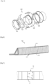
- FIG 5 shows, in exploded view, an air inlet 201 of nacelle 200 of an aircraft propulsion assembly as shown figure 4 .
- the air inlet 201 comprises structural elements such as a front frame 101 and a rear frame 104, as well as, upstream and downstream of the nacelle 200, a lip 100 carried by the front frame 101, panels external walls 102 extending the lip 100 outside the nacelle 200 (and forming an external wall of the air inlet), an internal wall 103 extending the lip inside the nacelle and delimiting a central conduit allowing channel the air towards the engine, the external panels and the internal wall being carried by the front frame 101 and the rear frame 104.
- the shape of the air inlet and the systems with which it is equipped must make it possible to avoid the formation and/or accumulation of ice or frost, to ensure an aerodynamic function, to prevent the penetration of birds into the blower compartment containing the engine systems, as well as limiting the impact of noise pollution.
- the internal wall 103 is an acoustic panel, shown for example Figure 6 sectional.
- the core 112 comprises cells with a diaphragm according to one of the embodiments of the invention.
- this panel can incorporate a heating element, for example in the form of a heating tube or wire.
- an acoustic panel can be formed from various basic cellular structures, the cells of which can be provided with different diaphragms, it is interesting to be able to have a method of producing at least the cellular structure for soundproofing and a diaphragm insertion tool that is adaptable to different configurations.
- FIG. 7 schematically shows a section of cells 11 of a basic cell structure, for example as illustrated figure 1 or any other form of base section S or height H.
- Each cell 11 has an internal wall 16.
- FIG. 8 illustrates a step of gripping the diaphragm 20 by an insertion tool 30 according to an exemplary embodiment of the invention.
- Such an insertion tool 30 is for example schematized figures 9 a) and b) , according to two embodiment variants.
- the insertion tool 30 comprises at least one tip 31 which is configured to insert into the cell 11, with the diaphragm 20.
- the tip 31 includes for example a gripping system which is configured to hold part of the diaphragm 20, and release it.
- the gripping system comprises at least one channel 32, called suction channel 32, which is configured to be placed at least under negative pressure.
- the suction channel 32 is thus configured to hold the diaphragm 20 by suction, by suction cup effect.
- the end piece 31 has a bore 34 which extends from a top of the end piece 31.
- Such a bore 34 is configured to receive a tube of the diaphragm, for example a tube 23 of a diaphragm 20 as shown figure 2 And 3 .
- the suction channel 32 opens into the bore 34.
- the suction channel 32 opens into a groove 33 dug in a wall of the bore 34, here all around the bore 34, so that suction can be carried out all around part of the tube.
- the bore 34 comprises a deep, cylindrical part, and an opening, flared part, here frustoconical for example.
- the groove 33 is dug in the deep, cylindrical part, so that it would be facing a side wall of the tube when a diaphragm is taken by the tool.
- the groove 33 is dug in the opening, frustoconical part, so that it would then find itself opposite one end of the tube when a diaphragm is taken by the tool, or even an interface between the tube and the membrane.
- Such a configuration is for example interesting for a diaphragm having a low tube height.
- the end piece 31 has a side wall 35.
- the external side wall 35 is for example cylindrical so that it can be easily inserted into all types of cells.
- the end piece 31 here comprises a pressure application system 36, arranged on the external side wall 35.
- Such a pressure application system 36 is mainly configured to press and press a part of the diaphragm 20 against the internal wall 16 of the cell 11, in particular to fix it there.
- the pressure application system 36 includes an inflatable bladder 37.
- the inflatable bladder 37 is then configured to be inflated to press a portion of the diaphragm 20 against the wall 16 of the cell when the diaphragm is positioned in the cell 11, and to be deflated otherwise.
- the pressure application system may include an injection channel 38 configured to supply pressurized air.
- the injection channel 38 and the suction channel 32 are formed by a single channel which is selectively placed in depression or supplied with air under pressure.
- the insertion tool 30 is configured to take and hold a diaphragm 20 by suction of a portion of the diaphragm 20 using the suction channel 32, which creates a suction cup effect.
- FIG. 10 illustrates a step of inserting the diaphragm 20 into a cell 11 by the insertion tool 30 which holds it by depression in the suction channel 32.
- the step of inserting the diaphragm 20 into the cell 11 includes a step of pushing the diaphragm 20 into the cell 11 by the insertion tool 30.
- a part of the membrane of the diaphragm finds itself folded on the same side as the tube, thus covering the insertion tool 30.
- the method may include a step of pressing the part of the diaphragm 20 against the wall 16 of the cell 11 for its fixation.
- the membrane When the membrane is larger than the section of the cell, it can naturally press against the internal wall 16 of the cell by elastic return.
- the pressure is for example produced here by the pressure application system 36 of the insertion tool 30 which presses the part of the diaphragm 20 against the wall 16 of the cell 11.
- the inflatable bladder 37 is inflated and presses part of the membrane 21 against the wall 16 of the cell 11.
- the method then comprises a step of fixing the part of the diaphragm 20, possibly pressed against the wall 16 of the cell 11.
- the fixing can be carried out by bonding, for example by an adhesive, which for example comprises a resin, or by welding for example, or any other means.
- the process may include a step of injecting an adhesive, filling a possible gap between a periphery of the membrane and the internal wall 16 of the cell, and fixing the diaphragm in the socket.
- the adhesive can advantageously be applied by spraying or dipping onto the external surfaces of the membrane 21.
- the method includes for example a step of releasing the diaphragm 20 by the insertion tool 30.
- this step comprises at least one step of stopping suction by the insertion tool 30 and possibly a step of stopping the application of pressure by the pressure application system 36; for example the inflatable bladder 37 is deflated.
- the suction channel 32 is then returned to ambient pressure for example.
- the suction channel 32 can also be configured to blow a slight air pressure to release the diaphragm more quickly, or even avoid adhesion between the diaphragm 20 and the insertion tool 30.
- FIG. 11 schematically illustrates the diaphragm 20 in place in the cell 11, released from the insertion tool 30.
- the method then includes a step of applying a resistive sheet 12 which covers the cells 11, including the diaphragm, on a first side of the cellular structure 10.
- the resistive sheet 12 can optionally be perforated. It forms a resistive surface allowing communication of the cells 11 with an external environment.
- the method can also include a step of applying a closing sheet 13 which closes the cells 11 on a second side of the cellular structure.
- Closing sheet 13 may be a full sheet. However, it may be a sheet with perforations.
- a full sheet is generally used for simple acoustic treatments, called SDOF (“Single Degree of Freedom”) and forms a rear skin configured to reflect acoustic waves.
- a perforated closing sheet is generally used for acoustic treatments called DDOF (“Double Degree of Freedom”) for which a stack of two layers of honeycomb is produced, the stages being separated by an intermediate porous skin formed by said sheet. closing 13.
- the external side wall 35 of the tip 31 of the insertion tool 30 comprises a frustoconical part 39, a section of which narrows towards the top of the insertion tool 30.
- the tip 31 of the insertion tool 30 differs from those of the Figure 9 in that the suction channel 32 opens onto a part of the external side wall 35, that is to say towards the outside and not towards the inside as on the Figure 9 , and in particular here, the suction channel 32 opens onto the frustoconical part 39.
- a tool such as the one shown Figure 12 is for example useful for taking and holding a diaphragm 20 on a side opposite the membrane 21 compared to that from which a tube 23 would extend.
- the frustoconical part 39 is then configured to be placed under one end of the tube 23 at the interface with the membrane 21, for example around an orifice 22.
- the insertion tool 30 then holds the diaphragm 20 by suction of a part of the diaphragm 20 around the orifice 22.
- the insertion tool 30 makes it possible to insert the diaphragm 20 into the socket 11 by traction.
- the suction channel 32 can also be configured to blow air pressure to release the diaphragm 20 more quickly, or even avoid adhesion between the diaphragm 20 and the insertion tool 30.
- FIG 13 shows diaphragms 20', 20", 20'" and an insertion tool 30 according to other examples of implementation of the invention.
- the diaphragm 20' here comprises for example a membrane 21' and a tube 23' whose free end forming an acoustic outlet 24' here comprises a plurality of micro-perforations.
- the diaphragm 20" comprises here for example a membrane 21" which has an undulation, and a tube 23", here analogous to the tube 23 described previously, the acoustic outlet 24" of which has a hole of dimension equal to that of a diameter of the 23" tube.
- the diaphragm 20' here comprises a membrane 21′′′ which has an undulation, like the membrane 21", and a tube 23'" whose acoustic outlet 24'" has a plurality of micro-perforations, in a manner similar to that of the tube 23'.
- the acoustic output of the tube could include a woven zone.
- each of these diaphragms 20', 20", 20'” can possibly be inserted into a cell 11 by an insertion tool 30 according to the invention, for example as illustrated here.
- the end piece 31 is for example configured to hold the diaphragm 20', 20", 20'" by a part of its membrane 21', 21", 21′′′, in particular close to its periphery.
- the suction channel 32 opens here onto a part of the external side wall 35.
- the suction channel 32 can optionally also be configured to inject air pressure to release the diaphragm 20', 20", 20'" more quickly, or even avoid adhesion between the diaphragm 20', 20. ", 20'" and insertion tool 30.
- suction channel 32 can also be configured to allow a more powerful injection, for example air under high pressure, and thus form an injection channel 38 of a pressure application system configured to provide a air under pressure to press part of the membrane 21', 21", 21′′′ against the wall 16 of the cell 11.
- the at least one undulation can be static.
- the at least one corrugation can be configured to allow deployment of the membrane.
- the method may include a suction step, for example during a cooking step, to deploy the diaphragm.
Landscapes
- Engineering & Computer Science (AREA)
- Aviation & Aerospace Engineering (AREA)
- Chemical & Material Sciences (AREA)
- Combustion & Propulsion (AREA)
- Physics & Mathematics (AREA)
- Acoustics & Sound (AREA)
- Multimedia (AREA)
- Mechanical Engineering (AREA)
- Textile Engineering (AREA)
- Soundproofing, Sound Blocking, And Sound Damping (AREA)
Description
- La présente invention concerne une structure alvéolaire, et plus particulièrement une structure alvéolaire d'insonorisation.
- Elle concerne aussi un procédé de fabrication d'une telle structure alvéolaire, ainsi qu'un outil pour mettre en oeuvre le procédé.
- La structure alvéolaire peut avoir différentes applications, en particulier dans le domaine aéronautique, par exemple dans une nacelle d'aéronef.
- Une structure alvéolaire désigne ici une structure comportant des cellules ou alvéoles, c'est-à-dire des volumes unitaires creux juxtaposés.
- Une telle structure peut être réalisée en divers matériaux, par exemple plastiques, composites, ou métalliques. Les cellules peuvent présenter diverses géométries. Une forme bien connue de structure alvéolaire présente des cellules en forme de prisme droit de base hexagonale. On parle souvent de structure « en nid d'abeilles » pour désigner ce type de structure à cellules hexagonales, mais cette expression est parfois employée par abus de langage pour désigner des panneaux alvéolaires présentant toutes autres formes de cellules.
- Une telle structure peut être employée dans de nombreux domaines techniques, notamment dans le domaine aéronautique.
- Par exemple, une nacelle d'ensemble propulsif d'aéronef comporte généralement une entrée d'air qui est une structure acoustique devant assurer un traitement acoustique d'une partie avant de la nacelle et absorber des éventuelles nuisances sonores pouvant provenir d'une hélice d'un moteur.
- L'entrée d'air comporte, traditionnellement, un panneau acoustique qui assure principalement le traitement acoustique et une grande partie d'un comportement aérodynamique interne de l'entrée d'air.
- Le panneau acoustique peut être en composites et fabriqué en une seule pièce. Toute sa surface interne peut assurer le traitement acoustique.
- Dans ce contexte, le panneau acoustique peut être dimensionné pour résister à diverses contraintes, comme par exemple une perte de pale de l'hélice, un chargement aérodynamique (surpression) sur tout un périmètre interne du panneau acoustique, un choc d'oiseau, différentes sollicitations thermiques, etc.
- A ces fins, au moins une partie du panneau acoustique comprend classiquement une âme en structure alvéolaire (dit abusivement « en nid d'abeilles ») qui est configurée pour amortir des nuisances sonores, interposée entre une peau acoustique (« résistive skin ») formant une première face et une peau arrière structurale (« backing skin ») formant une deuxième face du panneau acoustique.
- Un objectif de la peau acoustique est de laisser passer du bruit. Elle est par exemple composée de plusieurs couches dont une couche poreuse, présentant souvent des trous.
- La peau arrière structurale a notamment pour fonction d'assurer un rôle de réflecteur acoustique, ainsi que de fortement participer à la tenue structurale du panneau acoustique.
- En jouant sur une épaisseur du panneau acoustique, il est possible d'atténuer des hautes ou basses fréquences : plus le panneau est épais, plus les fréquences atténuées sont basses.
- Des ensembles propulsifs utilisent parfois un moteur à fort taux de dilution qui, pour un niveau de poussée identique, présente des dimensions plus larges et plus courtes, des pales de fans de plus grandes dimensions pouvant être associées à des vitesses de rotation plus faible qu'un moteur traditionnel. Les fréquences à atténuer sont alors plus basses.
- Or, les panneaux acoustiques connus dans l'état de la technique sont généralement efficaces à une fourchette étroite de fréquences dominantes de ce type de moteur seulement.
- Pour atténuer des fréquences sur une gamme plus large, le brevet
US 7 857 093 B2 propose par exemple de superposer deux couches de nid d'abeilles pour absorber des fréquences plus basses. - Toutefois, une telle solution entraine de fait un encombrement plus important. Une épaisseur du panneau acoustique est augmentée de façon significative, entrainant une augmentation de masse et de rigidité dudit panneau acoustique.
- Le document
GB2005384 - Le document
US2015041248 décrit une structure acoustique comprenant un nid d'abeilles dont les cellules forment avec une barrière acoustique des résonateurs acoustiques. Chaque résonateur comprend un conduit tronconique présentant une partie perméable. - Le document
FR3055662 - A cet effet, est proposé, selon un premier aspect, une structure alvéolaire d'insonorisation comportant au moins une alvéole ayant une section de base S de forme quelconque et une hauteur H, caractérisée en ce que l'alvéole comporte un diaphragme, le diaphragme comportant une membrane, divisant l'alvéole en deux compartiments selon la hauteur H, la membrane comportant au moins une ondulation et au moins un orifice traversant une épaisseur de la membrane, et le diaphragme comportant au moins un tube, entourant l'au moins un orifice et s'étendant depuis une face de la membrane dans un des deux compartiments, le tube comportant une extrémité libre formant une sortie acoustique qui est positionnée à distance p de la section de base S.
- Une telle structure alvéolaire est ainsi configurée pour traiter un spectre de fréquences acoustiques plus large qu'une structure alvéolaire sans diaphragme, c'est-à-dire de hautes et/ou basses fréquences acoustiques.
- Un tel tube permet plus particulièrement de traiter de plus basses fréquences. L'un des deux compartiments dans lequel s'étend le tube est alors configuré pour traiter des fréquences basses tandis que l'autre des deux compartiments est configuré pour traiter des fréquences hautes.
- Les deux compartiments communiquent alors acoustiquement, voire fluidiquement, entre eux par le tube.
- Comme un dimensionnement du tube est préalablement connu, un diaphragme selon l'invention permet ainsi un dimensionnement acoustique de la structure plus simple. En outre, un tel diaphragme est plus robuste industriellement. Un tel diaphragme peut être adapté à un grand nombre d'alvéoles, différentes en forme et en dimensions.
- Au besoin, le diaphragme peut comporter plusieurs tubes, par exemple entre un et dix tubes.
- Un tube désigne ici un conduit présentant tout type de section, qui peut être de dimensions constantes ou pas sur la hauteur du tube, et formant une protubérance par rapport à la membrane. Il peut être cylindrique ou tronconique, à section polygonale ou circulaire.
- La sortie acoustique est une partie du diaphragme configurée pour transmettre des ondes acoustiques.
- Dans un exemple de réalisation, la sortie acoustique du tube comporte au moins un orifice, des micro-perforations et/ou une zone tissée.
- Ainsi, à partir de la structure alvéolaire de base choisie (c'est-à-dire initialement sans diaphragme), qui peut même être standard, le diaphragme est disposé dans l'alvéole en fonction des fréquences à traiter. Il est alors possible de traiter différentes gammes de fréquences avec une même structure alvéolaire de base et un même diaphragme, en fonction de la disposition du diaphragme dans l'alvéole de la structure alvéolaire. Autrement dit, un volume de chacun des compartiments est déterminé en fonction des fréquences visées.
- Eventuellement, la structure alvéolaire de base est choisie en fonction des volumes des compartiments voulus, par exemple en variant la hauteur de la structure alvéolaire. Par exemple, l'alvéole est une cellule monobloc.
- L'alvéole peut être réalisée en matière synthétique, de papier ou tissage revêtu ou enduit de résine ou autre produit améliorant la rigidité et l'imperméabilité, de matière composite, par exemple en thermoplastique, ou en métal, ou autre en fonction de l'application visée.
- L'alvéole est par exemple formée d'un cylindre droit, c'est-à-dire dont une génératrice est orthogonale à la section de base.
- La forme de la section de base peut varier. Celle-ci est par exemple déterminée en fonction des caractéristiques mécaniques recherchées pour la structure alvéolaire. Par exemple, la section de base à une forme circulaire ou hexagonale. En cas d'alvéole hexagonale, la structure alvéolaire correspond alors à une structure en nid d'abeille à proprement parler.
- Dans un exemple de réalisation, la distance p entre la section acoustique et la section de base S de l'alvéole vaut entre 20 % et 80 % de la hauteur H de l'alvéole.
- Dans un exemple de réalisation, la membrane comporte au moins une ondulation.
- Dans un exemple de réalisation, la structure alvéolaire d'insonorisation comporte une feuille résistive recouvrant l'alvéole d'un premier côté.
- Dans un exemple de réalisation, la structure alvéolaire d'insonorisation comporte une feuille de fermeture recouvrant l'alvéole d'un deuxième côté.
- Par exemple, la feuille de fermeture peut être perforée.
- Est également proposé, selon un autre aspect, un aéronef comprenant au moins un ensemble propulsif comprenant une nacelle.
- Par exemple, la nacelle comprend une entrée d'air comportant un panneau acoustique.
- Par exemple, le panneau acoustique comporte une structure alvéolaire d'insonorisation telle que décrite précédemment.
- Par exemple, une peau acoustique du panneau acoustique comporte la feuille résistive de la structure alvéolaire d'insonorisation.
- Par exemple, une peau arrière du panneau acoustique, configurée pour assurer une tenue structurale du panneau acoustique, comporte la feuille de fermeture de la structure alvéolaire d'insonorisation.
- Est également proposé, selon un autre aspect, un procédé de fabrication d'une structure alvéolaire d'insonorisation comportant :
- Une étape de fourniture d'au moins une alvéole ayant une section de base S de forme quelconque et une hauteur H ;
- Une étape de fourniture d'un diaphragme comportant une membrane, la membrane comportant au moins une ondulation et au moins un orifice traversant une épaisseur de la membrane,
et le diaphragme comportant au moins un tube surmontant l'orifice, le tube comportant une extrémité libre formant une sortie acoustique ; - Une étape de prise du diaphragme par un outil d'insertion comportant une étape de préhension d'une partie du diaphragme par l'outil d'insertion ;
- Une étape d'insertion du diaphragme dans l'alvéole par l'outil d'insertion jusqu'à positionner la sortie acoustique à une distance p de la section de base S ;
- Une étape de fixation d'une partie du diaphragme contre une paroi de l'alvéole ; et
- Une étape de relâchement du diaphragme par l'outil d'insertion.
- Un tel procédé permet d'insérer différents types de diaphragmes dans différentes configurations d'alvéoles et la fixation du diaphragme dans celle-ci.
- En effet, les alvéoles d'une structure alvéolaire peuvent fortement varier, notamment en forme de section et en dimensions, d'une structure alvéolaire à une autre. Parallèlement, le diaphragme à insérer peut également varier en fonction des fréquences acoustiques à traiter et de la structure alvéolaire à laquelle il est destiné.
- Dans ce contexte, un tel procédé de réalisation d'une structure alvéolaire d'insonorisation, formée à partir d'au moins une structure alvéolaire dans au moins une alvéole de laquelle est inséré un diaphragme, est adaptable à différentes formes d'alvéoles et de diaphragmes.
- Ainsi, à partir de la structure alvéolaire de base choisie (c'est-à-dire initialement sans diaphragme), qui peut même être standard, le diaphragme est disposé dans l'alvéole en fonction des fréquences à traiter, c'est-à-dire à une distance prédéterminée d'une section de base de l'alvéole. Il est alors possible de traiter différentes gammes de fréquences avec une même structure alvéolaire de base et un même diaphragme, en fonction de la disposition du diaphragme dans l'alvéole de la structure alvéolaire. Dans un exemple de mise en oeuvre, l'étape de préhension d'une partie du diaphragme comporte une étape d'aspiration par l'outil d'insertion.
- Dans un exemple de mise en oeuvre, l'étape de relâchement comporte une étape d'arrêt d'aspiration d'une partie du diaphragme par l'outil d'insertion.
- Dans un exemple de mise en oeuvre, le procédé comporte une étape de pression de la partie du diaphragme contre la paroi de l'alvéole pour sa fixation par un système d'application de pression de l'outil d'insertion.
- Est aussi proposé, selon la revendication 8, un outil d'insertion d'un diaphragme dans une alvéole d'une structure alvéolaire d'insonorisation.
- L'outil d'insertion comporte au moins un embout configuré pour s'insérer dans l'alvéole.
- L'embout comporte au moins un système de préhension configuré pour maintenir une partie du diaphragme ou le relâcher.
- Dans un exemple de réalisation, le système de préhension comporte un canal d'aspiration configuré pour être mis en dépression et maintenir une partie du diaphragme.
- Dans un exemple de réalisation, l'embout comporte un système d'application de pression configuré pour plaquer une partie de la membrane contre la paroi interne de l'alvéole.
- L'invention, selon un exemple de réalisation, sera bien comprise et ses avantages apparaitront mieux à la lecture de la description détaillée qui suit, donnée à titre indicatif et nullement limitatif, en référence aux dessins annexés dans lesquels :
- la
figure 1 représente, selon une vue schématique en perspective, une structure alvéolaire d'insonorisation ; - la
figure 2 présente une série d'alvéoles permettant de constituer une structure alvéolaire telle que celle de lafigure 1 mettant en oeuvre un exemple de réalisation selon l'invention ; - la
figure 3 montre, en coupe, une alvéole de structure alvéolaire selon un exemple de réalisation de l'invention tel que schématiséfigure 2 ; - la
figure 4 est une vue en perspective d'un aéronef comportant une nacelle ayant une entrée d'air ; - la
figure 5 montre schématiquement, en éclaté, une entrée d'air de nacelle telle que représentéefigure 4 ; - la
figure 6 est une coupe latérale d'un panneau acoustique d'une entrée d'air telle qu'illustréefigure 5 ; - la
figure 7 montre schématiquement une coupe d'alvéoles d'une structure alvéolaire de base, par exemple telle qu'illustréefigure 1 ; - la
figure 8 illustre une étape de prise d'un diaphragme par un outil d'insertion selon un exemple de réalisation de l'invention ; - la
figure 9 représente schématiquement deux exemples de réalisation de l'outil d'insertion selon l'invention ; - la
figure 10 illustre une étape d'insertion du diaphragme dans une alvéole en le maintenant par l'outil d'insertion, selon le mode de réalisation de lafigure 8 ; - la
figure 11 représente schématiquement le diaphragme en place dans l'alvéole ; - la
figure 12 illustre une étape d'insertion du diaphragme dans une alvéole en le maintenant par un outil d'insertion selon un autre exemple de réalisation ; et - la
figure 13 montre des diaphragmes et un outil d'insertion selon d'autres exemples de réalisation de l'invention. - Les éléments identiques représentés sur les figures précitées sont identifiés par des références numériques identiques.
- La
figure 1 représente schématiquement une structure alvéolaire d'insonorisation 10 traditionnelle, ou de base. - Elle comporte des alvéoles (également désignées cellules ou cavités) 11 juxtaposées les unes aux autres selon deux directions orthogonales entre elles. Une troisième direction, orthogonale aux deux précédentes, correspond à une épaisseur de la structure alvéolaire, également définie par une hauteur H des alvéoles 11.
- Dans l'exemple représenté
figure 1 , la structure alvéolaire est munie, d'un premier côté de la structure alvéolaire, d'une feuille résistive 12 qui recouvre les alvéoles 11. La feuille résistive 12 est éventuellement perforée. Elle forme une surface résistive permettant la communication des alvéoles 11 avec un environnement extérieur. - D'un deuxième côté de la structure alvéolaire, la structure alvéolaire est munie d'une feuille de fermeture (peau arrière) 13 qui ferme les alvéoles 11.
- La feuille de fermeture 13 peut être une feuille pleine. Néanmoins, il peut s'agir d'une feuille présentant des perforations. Une feuille pleine est généralement employée pour des traitements acoustiques simples, dits SDOF (« Single Degree of Freedom ») et forme une peau arrière configurée pour réfléchir des ondes acoustiques. Une feuille de fermeture perforée est généralement employée pour des traitements acoustiques dits DDOF (« Double Degree of Freedom ») pour lesquels un empilement de deux étages de nid d'abeille est réalisé, les étages étant séparés par une peau poreuse intermédiaire formée par ladite feuille de fermeture 13.
- Sur la
figure 1 , afin de mieux montrer la structure alvéolaire, la feuille ou couche résistive 12 est représentée ne recouvrant seulement qu'une partie des alvéoles 11. Les alvéoles 11 de la structure alvéolaire 10 ici représentées sont dites hexagonales, leur volume est celui d'un cylindre droit, de section de base S hexagonale, s'étendant entre la feuille résistive 12 et la feuille de fermeture 13 sur la hauteur H. - Les alvéoles sont en outre disposées en quinconce, en étant imbriquées les unes par rapport aux autres, ici sans définir de volume mort.
- La
figure 2 présente une série d'alvéoles 11 permettant de constituer une structure alvéolaire 10, analogue à que celle de lafigure 1 , mettant en oeuvre un exemple de réalisation selon l'invention. - Par exemple, l'alvéole 11 est une cellule monobloc.
- Les alvéoles 11 ont ici une section de base S hexagonale, comme celles de la
figure 1 , mais elles pourraient avoir toute autre forme, notamment au moins en partie circulaire. La section de base S désigne ici une section de l'alvéole à une extrémité de l'alvéole. De plus, par définition ici, l'alvéole 11 comporte une paroi interne 16 (indiquéefigure 3 ). - Selon des formes de réalisation, l'alvéole est formée par la paroi interne 16, la feuille résistive 12 et la feuille de fermeture 13. La paroi 16 s'étend jusqu'à la feuille résistive 12. La paroi 16 s'étend à l'opposé jusqu'à la feuille de fermeture 13.
- L'alvéole 11 peut être réalisée en matière synthétique, par exemple en matrice thermoplastique, papier ou tissage de fibre revêtu de résine, ou en métal, ou autre en fonction de l'application visée.
- Selon l'invention, l'alvéole 11 de la
figure 2 comporte un diaphragme 20 disposé selon une section de l'alvéole 11. - Le diaphragme 20 est par exemple réalisé au moins en partie en élastomère (par exemple en silicone, ...) en métal, en thermoplastique, en résine, ou autre.
- Le diaphragme 20 comporte au moins une membrane 21.
- La membrane 21 est par exemple collée, par un adhésif, une résine, ou brasée ou soudée dans l'alvéole 11, notamment ici à la paroi interne 16 de l'alvéole ou en bordure de celle-ci.
- La membrane peut avoir un pourtour de toute forme, par exemple de forme circulaire, ce qui lui permet de s'adapter à un grand nombre de formes de section d'alvéole.
- Par exemple, le diaphragme 20 obture toute une section de l'alvéole 11 dans laquelle il est disposé, soit par lui-même soit en coopération avec un adhésif ou autre matériau qui comblerait un éventuel interstice entre au moins une partie du pourtour de la membrane 21 et la paroi interne 16 de l'alvéole, de sorte que le diaphragme 20 divise l'alvéole 11 en deux compartiment 14, 15 (indiqués
figure 3 ). - Dans un exemple de réalisation, la membrane peut présenter une dimension transverse, par exemple une diagonale ou un diamètre si elle a un pourtour de forme circulaire, inférieure ou égale à dimension correspondante de la section de l'alvéole où la membrane est disposée, laissant ainsi possiblement un interstice entre au moins une partie du pourtour de la membrane 21 et la paroi interne 16 de l'alvéole qui serait alors possiblement comblé par un adhésif ou autre.
- Par exemple, la membrane 21 peut être relativement indéformable, rigide, pouvant en contrepartie présenter une plus faible épaisseur lui procurant plus de légèreté.
- Un tel diaphragme est par exemple réalisé en matériau composite.
- Dans un autre exemple de réalisation, le diaphragme 20 peut présenter une dimension transverse, par exemple un diamètre, supérieure à une dimension correspondante de la section de l'alvéole dans laquelle il est disposé, de sorte qu'il obture toute la section par lui-même.
- De fait, pour son introduction dans celle-ci, la membrane est alors par exemple configurée pour se comprimer pour y pénétrer.
- Dans un tel cas, la membrane peut comporter au moins une ondulation.
- L'au moins une ondulation peut être préformée dans la membrane 21, et/ou être induite par la compression de la membrane lorsqu'elle est positionnée dans l'alvéole 11.
- Un avantage à une ondulation préformée est qu'elle permet une extension de la membrane par rapport à sa position de repos, en plus de faciliter et guider des déformations en compression, selon le besoin.
- Selon un exemple de réalisation, l'au moins une ondulation peut être statique.
- Selon un autre exemple de réalisation, l'au moins une ondulation peut être configurée pour permettre un déploiement de la membrane.
- Ceci permet notamment de fabriquer et stocker le diaphragme sur une moindre hauteur, ce qui permet un gain de place.
- Une adhésion entre le diaphragme 20 et la cellule 11 de la structure alvéolaire 10 est par exemple réalisée grâce à un adhésif complété par un effet naturel de pression qu'offre la membrane 21 sur la paroi interne 16 de la cellule (la membrane cherchant revenir à son état libre une fois insérée dans l'alvéole).
- Dans le cas d'une cellule 11 en matériau thermoplastique et d'un diaphragme 20 aussi en matériau thermoplastique, la liaison entre eux pourra être réalisée par soudure, sans besoin d'adhésif.
- Ainsi, dans un exemple de réalisation, la membrane 21 a une souplesse et déformabilité qui sont configurées pour s'adapter aux variations de formes et de tolérances de la structure alvéolaire, soit par exemple de l'ordre de 1 à 3 mm au rayon. Le diaphragme 20 comporte en outre une zone centrale ouverte d'un point de vue acoustique, et en particulier ici un tube 23 qui s'étend depuis une face de la membrane 21.
- Le tube 23 désigne ici un conduit présentant tout type de section, qui peut être de dimensions constantes ou pas sur la hauteur du tube, et formant une protubérance par rapport à la membrane. Il peut être cylindrique ou tronconique, à section polygonale ou circulaire.
- Une section polygonale est par exemple hexagonale.
- Par exemple, dans une structure alvéolaire à alvéoles hexagonales (NIDA classique), le tube a en particulier une section circulaire ou hexagonale.
- Tandis que dans une alvéole à section autre qu'hexagonale (par exemple dans une structure alvéolaire de coeur flexible, souvent dit « flexcore »), le tube a plus particulièrement une section circulaire, et est plutôt tronconique.
- Les deux compartiments ne communiquent acoustiquement entre eux que par le tube 23, la membrane 21 étant scellée sur son pourtour à la paroi interne 16 de l'alvéole 11.
- Une extrémité libre du tube, formant une sortie acoustique, peut comporter par exemple une section entièrement ouverte, un trou, comme représenté sur la
figure 3 , oufigure 13 pour le tube 23", ou elle pourrait comporter une paroi poreuse, un ensemble de micro-perforations, ou un tissage, par exemple métallique, par exemple comme illustrée sur lafigure 13 , sous les références 23' et 23‴. - Un tel tube 23 est configuré pour maintenir une zone indéformable et favoriser une zone déformable autour de cette zone indéformable. Il permet de marquer une interface physique qui accentue une adaptabilité de la membrane en préservant la zone acoustique.
- Il est ainsi possible de ne pas déformer la sortie acoustique, étant précisé qu'il est ici considéré qu'il n'y a pas de déformation de la zone acoustique dans une tolérance de moins de 10% de variation de section de la sortie acoustique, ce qui équivaut à environ 10% de perte de charge.
- Selon une caractéristique du diaphragme selon ce mode de réalisation, la zone centrale acoustiquement ouverte, soit le tube 23, a une rigidité au moins égale à une rigidité de la membrane 21.
- Cela peut par exemple être réalisé par une épaisseur plus importante pour cette zone centrale ouverte (le tube 23 en particulier) que pour la membrane 21 alors qu'ils sont réalisés en un même matériau.
- La
figure 3 montre une alvéole 11 telle que celles de lafigure 2 en coupe. - Cette figure montre que le diaphragme 20 divise l'alvéole 11 en deux compartiments 14, 15. Le bord périphérique extérieur de la membrane est fixé à la paroi interne 16 de l'alvéole 11, entre les deux extrémités de ladite paroi 16 de l'alvéole dans la direction de la hauteur H de manière à pouvoir la diviser en deux compartiments 14, 15.
- A partir d'une structure alvéolaire choisie, la membrane 21 est disposée dans l'alvéole 11 en fonction des fréquences acoustiques à traiter.
- Par exemple, la membrane 21 est disposée selon une section de l'alvéole.
- Dans un exemple de réalisation, une intersection entre la membrane 21 et la paroi interne de l'alvéole 11 est disposée parallèlement à la section de base S et à distance de la section de base S.
- La membrane 21 comporte au moins une partie centrale ouverte, par exemple un orifice 22.
- L'orifice 22 est ici centré par rapport à la section de l'alvéole où est disposée la membrane 21.
- Le tube 23 surmonte l'orifice 22 et s'étend ici dans le compartiment 14.
- En particulier, le tube 23 s'étend à partir d'un bord de l'orifice 22, de sorte qu'un diamètre de l'orifice 22 est égal à un diamètre interne d du tube 23.
- Le tube 23 est ainsi également centré par rapport à la section de l'alvéole.
- L'extrémité libre du tube 23 formant une sortie acoustique 24 peut comporter un trou (comme sur la
figure 3 , oufigure 13 pour le tube 23") ou un ensemble de micro-perforations, ou un tissage, par exemple métallique, par exemple tels que schématisésfigure 13 (aux références 23' et 23‴). - Le tube 23, et en particulier la section de sortie acoustique 24, sont par exemple indéformables sous des sollicitations induites lors d'étapes d'insertion du diaphragme dans l'alvéole. Par exemple la section de sortie acoustique 24 demeure inchangée entre un état libre et lorsque le diaphragme est inséré dans l'alvéole dans une tolérance de 10% de variation de section de la sortie acoustique, ce qui équivaut à environ 10% de perte de charge.
- Au besoin, une capacité d'adaptation du diaphragme est procurée par la membrane qui est configurée pour se déformer en fonction des dimensions et forme de l'alvéole.
- Les deux compartiments 14, 15 communiquent alors acoustiquement, voire fluidiquement, entre eux par le tube 23.
- Le compartiment 14, dans lequel s'étend le tube 23, est ainsi configuré pour traiter des fréquences basses tandis que le compartiment 15, situé de l'autre côté du diaphragme 20 dans l'alvéole 11, est configuré pour traiter des fréquences hautes.
- Le tube 23 est ici cylindrique, par exemple à section circulaire. Selon un autre exemple de réalisation intéressant, il pourrait avoir une section hexagonale.
- Le tube 23 a ici une hauteur e égale à au moins trois fois son diamètre, et en particulier au moins trois fois le diamètre de la section de sortie acoustique 24 du tube 23.
- Le tube 23 a ici un diamètre interne de section constante sur toute sa hauteur e, ou par exemple constante sur au moins 50% de la hauteur e, à partir de la sortie acoustique 24.
- Le diaphragme 20 est disposé dans l'alvéole 11 en fonction des fréquences à traiter. Ainsi, à partir d'une structure alvéolaire choisie, le diaphragme est par exemple disposé avec la sortie acoustique 24 à une distance p de la section de base S, qui est déterminée en fonction des fréquences à traiter.
- Par exemple, la distance p est comprise entre 20 % et 80 % de la hauteur H.
- Le diaphragme est par exemple disposé avec la sortie acoustique 24 à un tiers de la hauteur, ou deux tiers ou à mi-hauteur selon une spécification acoustique donnée et des dimensions (hauteur et section) de l'alvéole de la structure alvéolaire considérée. Dans le présent exemple illustré sur les figures, la membrane 21 est située environ à mi-hauteur de l'alvéole, soit à environ 50 % de la hauteur H à partir de la section de base S, et la sortie acoustique 24 est ici à environ 25% de la hauteur.
- Un volume de chacun des compartiments 14, 15 varie donc en conséquence et sont ici sensiblement équivalents.
- Une telle structure alvéolaire avec un diaphragme permet ainsi de traiter une plus large gamme de fréquences acoustiques qu'une même structure alvéolaire sans diaphragme.
- Un diaphragme selon l'invention permet ainsi un dimensionnement acoustique plus simple. Les ondes acoustiques sont canalisées par le tube. Un tel diaphragme est plus robuste industriellement car il est plus facile de s'assurer que les ondes acoustiques sont reprises par le tube, ce qui est moins dépendant de la forme et de la taille de la section des alvéoles. En outre, un tel diaphragme peut être adapté à un grand nombre d'alvéoles, différentes en forme et en dimensions.
- La
figure 4 montre un aéronef biréacteur ayant deux nacelles 200 qui possèdent une entrée d'air 201. - La
figure 5 montre, en éclaté, une entrée d'air 201 de nacelle 200 d'ensemble propulsif d'aéronef tel que représentéfigure 4 . - L'entrée d'air 201 comprend des éléments de structure tels qu'un cadre avant 101 et un cadre arrière 104, ainsi que, d'amont en aval de la nacelle 200, une lèvre 100 portée par le cadre avant 101, des panneaux externes 102 prolongeant la lèvre 100 à l'extérieur de la nacelle 200 (et formant une paroi externe de l'entrée d'air), une paroi interne 103 prolongeant la lèvre à l'intérieur de la nacelle et délimitant un conduit central permettant de canaliser l'air en direction du moteur, les panneaux externes et la paroi interne étant portés par le cadre avant 101 et le cadre arrière 104.
- La forme de l'entrée d'air et les systèmes dont elle est équipée doivent permettre d'éviter la formation et/ou l'accumulation de glace ou givre, d'assurer une fonction aérodynamique, de prévenir la pénétration d'oiseaux dans le compartiment de soufflante contenant les systèmes moteurs, ainsi que de limiter l'impact des nuisances sonores.
- Pour remplir ce dernier objectif, la paroi interne 103 est un panneau acoustique, représenté par exemple
figure 6 en coupe. - Le panneau acoustique 103 comporte alors une structure alvéolaire telle que décrite précédemment, soit par exemple :
- une peau dite acoustique ou résistive 111, poreuse, perforée ou micro-perforée, qui forme par exemple une face visible du panneau (c'est-à-dire une face orientée vers l'intérieur du conduit central de l'entrée d'air) ; l'objectif de cette peau résistive est de laisser passer les ondes sonores et éventuellement aussi de dissiper au moins partiellement l'énergie de celles-ci sous forme thermique,
- une peau arrière 113, qui a essentiellement pour fonction d'assurer la tenue structurale du panneau acoustique, et
- une âme 112, de part et d'autre de laquelle sont fixées la peau résistive 111 et la peau arrière 113, laquelle âme participe à la fois à la tenue mécanique et à l'amortissement acoustique, la fonction principale de l'âme étant d'emprisonner et amortir les ondes sonores.
- Ici, l'âme 112 comporte des alvéoles avec diaphragme selon un des exemples de réalisation de l'invention.
- Dans le cas où le panneau acoustique est en zone pouvant capter de la glace ou du ruissellement, ce panneau peut incorporer un élément chauffant, par exemple sous forme de tube ou de fil chauffants.
- Toutefois, un panneau acoustique pouvant être formé à partir de diverses structures alvéolaires de base, dont les alvéoles peuvent être munies de différents diaphragmes, il est intéressant de pouvoir disposer d'un procédé de réalisation d'au moins la structure alvéolaire d'insonorisation et d'un outil d'insertion de diaphragmes qui soient adaptables à différentes configurations.
- La
figure 7 montre schématiquement une coupe d'alvéoles 11 d'une structure alvéolaire de base, par exemple telle qu'illustréefigure 1 ou de toute autre forme de section de base S ou hauteur H. - Chaque alvéole 11 présente une paroi interne 16.
- Afin de positionner un diaphragme 20 dans une alvéole 11 telle que schématisée
figure 7 , lafigure 8 illustre une étape de prise du diaphragme 20 par un outil d'insertion 30 selon un exemple de réalisation de l'invention. - Un tel outil d'insertion 30 est par exemple schématisé
figures 9 a) et b) , selon deux variantes de réalisation. - L'outil d'insertion 30 selon l'invention comporte au moins un embout 31 qui est configuré pour s'insérer dans l'alvéole 11, avec le diaphragme 20.
- L'embout 31 comporte par exemple un système de préhension qui est configuré pour maintenir une partie du diaphragme 20, et le relâcher.
- Dans l'exemple de réalisation schématisé sur les figures, le système de préhension comporte au moins un canal 32, dit canal d'aspiration 32, qui est configuré pour être mis au moins en dépression.
- Le canal d'aspiration 32 est ainsi configuré pour maintenir le diaphragme 20 par aspiration, par effet ventouse.
- Sur ces figures, l'embout 31 comporte un alésage 34 qui s'étend depuis un sommet de l'embout 31.
- Un tel alésage 34 est configuré pour recevoir un tube du diaphragme, par exemple un tube 23 d'un diaphragme 20 tel que représenté
figures 2 et3 . - Pour un tel diaphragme, il peut alors être particulièrement commode de le maintenir par le tube.
- Pour cela, le canal d'aspiration 32 débouche dans l'alésage 34.
- En particulier, le canal d'aspiration 32 débouche dans une gorge 33 creusée dans une paroi de l'alésage 34, ici tout autour de l'alésage 34, pour que l'aspiration puisse être réalisée tout autour d'une partie du tube.
- Pour un maintien du diaphragme 20 limitant des risques d'endommagement du diaphragme 20, en particulier à une interface entre le tube et la membrane qui peuvent être réalisés conjointement d'une seule pièce ou de manières dissociées et assemblés ultérieurement, l'alésage 34 comporte une partie profonde, cylindrique, et une partie débouchante, évasée, ici tronconique par exemple.
- Dans l'exemple de réalisation de la
figure 9 a) , la gorge 33 est creusée dans la partie profonde, cylindrique, de sorte qu'elle se retrouverait en vis-à-vis d'une paroi latérale du tube lorsqu'un diaphragme est pris par l'outil. - Dans l'exemple de réalisation de la
figure 9 b) , la gorge 33 est creusée dans la partie débouchante, tronconique, de sorte qu'elle se retrouverait alors en vis-à-vis d'une extrémité du tube lorsqu'un diaphragme est pris par l'outil, voire une interface entre le tube et la membrane. Une telle configuration est par exemple intéressante pour un diaphragme ayant un tube de faible hauteur. - Extérieurement, l'embout 31 comporte une paroi latérale 35.
- La paroi latérale externe 35 est par exemple cylindrique pour pouvoir être insérée facilement dans tous types d'alvéoles.
- Selon une option intéressante, l'embout 31 comporte ici un système d'application de pression 36, disposé sur la paroi latérale externe 35.
- Un tel système d'application de pression 36 est principalement configuré pour plaquer et presser une partie du diaphragme 20 contre la paroi interne 16 de l'alvéole 11, notamment pour la l'y fixer.
- Dans l'exemple de réalisation illustré
figures 9 a) et 9 b) , le système d'application de pression 36 comporte une vessie gonflable 37. - La vessie gonflable 37 est alors configurée pour être gonflée pour presser une partie du diaphragme 20 contre la paroi 16 de l'alvéole lorsque le diaphragme est positionné dans l'alvéole 11, et pour être dégonflée sinon.
- Selon un autre exemple de réalisation représenté
figure 13 , le système d'application de pression peut comporter un canal d'injection 38 configuré pour fournir un air sous pression. - Eventuellement, dans cet exemple de réalisation, le canal d'injection 38 et le canal d'aspiration 32 sont formés par un seul et même canal qui est sélectivement mis en dépression ou alimenté en air sous pression.
- Ainsi, lors d'une première étape, l'outil d'insertion 30 est configuré pour prendre et maintenir un diaphragme 20 par aspiration d'une partie du diaphragme 20 grâce au canal d'aspiration 32, ce qui crée un effet ventouse.
- La
figure 10 illustre ensuite une étape d'insertion du diaphragme 20 dans une alvéole 11 par l'outil d'insertion 30 qui le maintient par dépression dans le canal d'aspiration 32. - Dans cet exemple, l'étape d'insertion du diaphragme 20 dans l'alvéole 11 comporte une étape de poussée du diaphragme 20 dans l'alvéole 11 par l'outil d'insertion 30. Comme illustré ici, lorsque la membrane est plus grande qu'une section correspondante de l'alvéole, une partie de la membrane du diaphragme se retrouve alors repliée d'un même côté que le tube, chapeautant ainsi l'outil d'insertion 30.
- Une fois le diaphragme 20 à la position souhaitée dans l'alvéole 11, le procédé peut comporter une étape de pression de la partie du diaphragme 20 contre la paroi 16 de l'alvéole 11 pour sa fixation.
- Lorsque la membrane est plus grande que la section de l'alvéole, elle peut se plaquer naturellement contre la paroi interne 16 de l'alvéole par retour élastique.
- La pression est par exemple réalisée ici par le système d'application de pression 36 de l'outil d'insertion 30 qui vient plaquer la partie du diaphragme 20 contre la paroi 16 de l'alvéole 11.
- Dans l'exemple illustré, la vessie gonflable 37 est gonflée et plaque une partie de la membrane 21 contre la paroi 16 de l'alvéole 11.
- Simultanément ou ultérieurement, le procédé comporte alors une étape de fixation de la partie du diaphragme 20, éventuellement pressée contre la paroi 16 de l'alvéole 11. La fixation peut être réalisée par collage, par exemple par un adhésif, lequel comporte par exemple une résine, ou par soudage par exemple, ou tout autre moyen.
- Il s'agit par exemple d'un adhésif de type résine époxy.
- Si le diaphragme est de dimension inférieure à la section correspondante de l'alvéole, le procédé peut comporter une étape d'injection d'un adhésif, comblant un éventuel interstice entre un pourtour de la membrane et la paroi interne 16 de l'alvéole, et fixant le diaphragme dans l'alvéole.
- Il s'agit par exemple d'un adhésif de type résine époxy, d'un adhésif souple ou d'un élastomère qui permet de combler un tel interstice.
- L'adhésif peut avantageusement être apporté par pulvérisation ou trempage sur les surfaces externes de la membrane 21.
- Avant ou après l'étape de fixation, le procédé comporte par exemple une étape de relâchement du diaphragme 20 par l'outil d'insertion 30.
- Pour cela, cette étape comporte au moins une étape d'arrêt d'aspiration par l'outil d'insertion 30 et éventuellement une étape d'arrêt d'application de pression par le système d'application de pression 36 ; par exemple la vessie gonflable 37 est dégonflée.
- Le canal d'aspiration 32 est alors remis à la pression ambiante par exemple. Optionnellement, le canal d'aspiration 32 peut aussi être configuré pour insuffler une légère pression d'air pour libérer le diaphragme plus rapidement, voire éviter une adhérence entre le diaphragme 20 et l'outil d'insertion 30.
- La
figure 11 illustre schématiquement le diaphragme 20 en place dans l'alvéole 11, dégagé de l'outil d'insertion 30. - Avec un tel procédé, il est notamment possible d'insérer plus d'un diaphragme, quel qu'il soit, dans une même alvéole 11.
- Il est ensuite possible de poursuivre la réalisation de la structure alvéolaire d'insonorisation.
- Par exemple, le procédé comporte ensuite une étape d'application d'une feuille résistive 12 qui recouvre les alvéoles 11, incluant le diaphragme, d'un premier côté de la structure alvéolaire 10.
- La feuille résistive 12 peut éventuellement être perforée. Elle forme une surface résistive permettant la communication des alvéoles 11 avec un environnement extérieur.
- Le procédé peut aussi comporter une étape d'application d'une feuille de fermeture 13 qui ferme les alvéoles 11 d'un deuxième côté de la structure alvéolaire.
- La feuille de fermeture 13 peut être une feuille pleine. Néanmoins, il peut s'agir d'une feuille présentant des perforations. Une feuille pleine est généralement employée pour des traitements acoustiques simples, dits SDOF (« Single Degree of Freedom ») et forme une peau arrière configurée pour réfléchir des ondes acoustiques. Une feuille de fermeture perforée est généralement employée pour des traitements acoustiques dits DDOF (« Double Degree of Freedom ») pour lesquels un empilement de deux étages de nid d'abeille est réalisé, les étages étant séparés par une peau poreuse intermédiaire formée par ladite feuille de fermeture 13.
- La
figure 12 montre un autre exemple de mise en oeuvre de la présente invention. - Sur cette figure, la paroi latérale externe 35 de l'embout 31 de l'outil d'insertion 30 comporte une partie tronconique 39, dont une section rétrécit en direction du sommet de l'outil d'insertion 30.
- En outre, l'embout 31 de l'outil d'insertion 30 diffère de ceux de la
figure 9 en ce que le canal d'aspiration 32 débouche sur une partie de la paroi latérale externe 35, c'est-à-dire vers l'extérieur et non vers l'intérieur comme sur lafigure 9 , et en particulier ici, le canal d'aspiration 32 débouche sur la partie tronconique 39. - Un outil tel que celui représenté
figure 12 est par exemple utile pour prendre et maintenir un diaphragme 20 d'un côté opposé de la membrane 21 par rapport à celui à partir duquel s'étendrait un tube 23. - La partie tronconique 39 est alors configurée pour se placer sous une extrémité du tube 23 à l'interface avec la membrane 21, par exemple autour d'un orifice 22.
- L'outil d'insertion 30 maintient alors le diaphragme 20 par aspiration d'une partie du diaphragme 20 autour de l'orifice 22.
- Dans l'exemple représenté, l'outil d'insertion 30 permet d'insérer le diaphragme 20 dans l'alvéole 11 par traction.
- Eventuellement, le canal d'aspiration 32 peut aussi être configuré pour insuffler une pression d'air pour libérer le diaphragme 20 plus rapidement, voire éviter une adhérence entre le diaphragme 20 et l'outil d'insertion 30.
- Enfin, la
figure 13 montre des diaphragmes 20', 20", 20'" et un outil d'insertion 30 selon d'autres exemples de mise en oeuvre de l'invention. - Le diaphragme 20' comporte ici par exemple une membrane 21' et un tube 23' dont l'extrémité libre formant une sortie acoustique 24' comporte ici une pluralité de micro-perforations.
- Le diaphragme 20" comporte ici par exemple une membrane 21" qui comporte une ondulation, et un tube 23", ici analogue au tube 23 décrit précédemment, dont la sortie acoustique 24" comporte un trou de dimension égale à celle d'un diamètre du tube 23".
- Le diaphragme 20'" comporte ici une membrane 21‴ qui comporte une ondulation, comme la membrane 21", et un tube 23'" dont la sortie acoustique 24'" comporte une pluralité de micro-perforations, de manière analogue à celle du tube 23'.
- Selon des exemples de réalisation non représentés, la sortie acoustique du tube pourrait comporter une zone tissée.
- Chacun de ces diaphragme 20', 20", 20'" peut possiblement être inséré dans une alvéole 11 par un outil d'insertion 30 selon l'invention, par exemple tel qu'illustré ici. En outre, dans cet exemple, l'embout 31 est par exemple configuré pour maintenir le diaphragme 20', 20", 20'" par une partie de sa membrane 21', 21", 21‴, notamment proche de sa périphérie.
- Pour cela, comme dans l'exemple de la
figure 12 , le canal d'aspiration 32 débouche ici sur une partie de la paroi latérale externe 35. - De même que précédemment, le canal d'aspiration 32 peut éventuellement être aussi configuré pour insuffler une pression d'air pour libérer le diaphragme 20', 20", 20'" plus rapidement, voire éviter une adhérence entre le diaphragme 20', 20", 20'" et l'outil d'insertion 30.
- En outre, le canal d'aspiration 32 peut aussi être configuré pour permettre une injection plus puissante, par exemple un air sous forte pression, et ainsi former un canal d'injection 38 d'un système d'application de pression configuré pour fournir un air sous pression pour presser une partie de la membrane 21', 21", 21‴ contre la paroi 16 de l'alvéole 11.
- Selon un exemple de réalisation, l'au moins une ondulation peut être statique.
- Selon un autre exemple de réalisation, l'au moins une ondulation peut être configurée pour permettre un déploiement de la membrane.
- Dans ce cas, le procédé peut comporter une étape d'aspiration, par exemple au cours d'une étape de cuisson, pour déployer le diaphragme.
- Ceci permet notamment de fabriquer et stocker le diaphragme sur une moindre hauteur, ce qui permet un gain de place.
Claims (9)
- Structure alvéolaire d'insonorisation (10) comportant des alvéoles (11) ayant une section de base (S) de forme quelconque et une hauteur (H), caractérisée en ce que chacune de ces alvéoles (11) comporte un diaphragme (20), le diaphragme (20) comportant une membrane (21), divisant l'alvéole (11) en deux compartiments (14, 15) selon la hauteur (H), la membrane (21) comportant au moins un orifice (22) traversant une épaisseur de la membrane, et le diaphragme (20) comportant au moins un tube (23), entourant l'au moins un orifice (22) et s'étendant depuis une face de la membrane (21) dans un des deux compartiments (14), le tube (23) comportant une extrémité libre formant une sortie acoustique (24) qui est positionnée à distance (p) de la section de base (S), la membrane (21) comportant au moins une ondulation.
- Structure alvéolaire d'insonorisation (10) selon la revendication 1, caractérisée en ce que la distance (p) entre la section acoustique (24) et la section de base (S) de l'alvéole (11) vaut entre 20 % et 80 % de la hauteur (H) de l'alvéole (11).
- Structure alvéolaire d'insonorisation (10) selon l'une quelconque des revendications 1 ou 2, dans lequel la sortie acoustique (24) du tube (23) comporte au moins un orifice, des micro-perforations et/ou une zone tissée.
- Structure alvéolaire d'insonorisation (10) selon l'une quelconque des revendications 1 à 3, caractérisée en ce qu'elle comporte une feuille résistive (12) recouvrant l'alvéole (11) d'un premier côté et une feuille de fermeture (13) recouvrant l'alvéole (11) d'un deuxième côté, la feuille de fermeture (13) étant perforée.
- Aéronef comprenant au moins un ensemble propulsif comprenant une nacelle (200), la nacelle (200) comprenant une entrée d'air (201) comportant un panneau acoustique (103), le panneau acoustique (103) comportant une structure alvéolaire (10) selon l'une quelconque des revendications 1 à 4, dont une peau acoustique (111) comporte la feuille résistive (12) et une peau arrière (113) configurée pour assurer une tenue structurale du panneau acoustique (103) comporte la feuille de fermeture (13).
- Procédé de fabrication d'une structure alvéolaire d'insonorisation (10) comportant une étape de fourniture d'au moins une alvéole (11) ayant une section de base (S) de forme quelconque et une hauteur (H) caractérisé en ce qu'il comprend :- Une étape de fourniture d'un diaphragme (20) comportant une membrane (21), la membrane (21) comportant au moins une ondulation et au moins un orifice (22) traversant une épaisseur de la membrane, et le diaphragme (20) comportant au moins un tube (23) surmontant l'orifice (22), le tube comportant une extrémité libre formant une sortie acoustique (24) ;- Une étape de prise du diaphragme (20) par un outil d'insertion (30) comportant une étape de préhension d'une partie du diaphragme (20) par l'outil d'insertion (30) ;- Une étape d'insertion du diaphragme (20) dans l'alvéole (11) par l'outil d'insertion (30) jusqu'à positionner la sortie acoustique (24) à une distance (p) de la section de base (S) ;- Une étape de fixation d'une partie du diaphragme (20) contre une paroi (16) de l'alvéole (11) ; et- Une étape de relâchement du diaphragme (20) par l'outil d'insertion (30).
- Procédé selon l'une quelconque la revendication 6, comportant une étape de pression de la partie du diaphragme (20) contre la paroi (16) de l'alvéole (11) pour sa fixation par un système d'application de pression (36) de l'outil d'insertion (30).
- Outil d'insertion (30) d'un diaphragme (20) dans une alvéole (11) d'une structure alvéolaire d'insonorisation (10) selon l'une quelconque des revendications 1 à 4, l'outil d'insertion (30) comportant au moins un embout (31) configuré pour s'insérer dans l'alvéole (11), l'embout (31) comportant au moins un système de préhension configuré pour maintenir une partie du diaphragme (20) ou le relâcher.
- Outil d'insertion (30) selon la revendication 8, caractérisé en ce que l'embout (31) comporte un système d'application de pression (36) configuré pour plaquer une partie de la membrane (21) contre la paroi interne (16) de l'alvéole (11).
Applications Claiming Priority (1)
| Application Number | Priority Date | Filing Date | Title |
|---|---|---|---|
| FR2005672A FR3111003A1 (fr) | 2020-05-29 | 2020-05-29 | Structure alvéolaire d’insonorisation incluant un diaphragme muni d’un tube configuré pour traiter différentes fréquences acoustiques, procédé de fabrication d'une telle structure, et outil associé |
Publications (2)
| Publication Number | Publication Date |
|---|---|
| EP3916717A1 EP3916717A1 (fr) | 2021-12-01 |
| EP3916717B1 true EP3916717B1 (fr) | 2023-12-06 |
Family
ID=73038063
Family Applications (1)
| Application Number | Title | Priority Date | Filing Date |
|---|---|---|---|
| EP21173044.5A Active EP3916717B1 (fr) | 2020-05-29 | 2021-05-10 | Structure alvéolaire d'insonorisation incluant un diaphragme muni d'un tube configuré pour traiter différentes fréquences acoustiques, procédé de fabrication d'une telle structure alvéolaire d'insonorisation, et outil associé |
Country Status (4)
| Country | Link |
|---|---|
| US (1) | US12014714B2 (fr) |
| EP (1) | EP3916717B1 (fr) |
| CN (1) | CN113734453A (fr) |
| FR (1) | FR3111003A1 (fr) |
Families Citing this family (1)
| Publication number | Priority date | Publication date | Assignee | Title |
|---|---|---|---|---|
| FR3085437B1 (fr) * | 2018-09-05 | 2020-11-20 | Airbus Operations Sas | Structure d’entree d’air d’une nacelle d’aeronef |
Family Cites Families (19)
| Publication number | Priority date | Publication date | Assignee | Title |
|---|---|---|---|---|
| US3887031A (en) * | 1973-06-11 | 1975-06-03 | Lockheed Aircraft Corp | Dual-range sound absorber |
| GB1499882A (en) * | 1975-02-14 | 1978-02-01 | Rolls Royce | Sound attenuating structure |
| US4106587A (en) * | 1976-07-02 | 1978-08-15 | The United States Of America As Represented By The Administrator Of The National Aeronautics And Space Administration | Sound-suppressing structure with thermal relief |
| GB2005384A (en) * | 1977-10-04 | 1979-04-19 | Rolls Royce | Multi-layer acoustic lining |
| US4231447A (en) * | 1978-04-29 | 1980-11-04 | Rolls-Royce Limited | Multi-layer acoustic linings |
| GB9413158D0 (en) * | 1994-06-30 | 1994-08-24 | Short Brothers Plc | Structural cellular component |
| CH691465A5 (de) * | 1995-04-20 | 2001-07-31 | Dornier Gmbh | Schallschutz für Nutzlastverkleidungen bei Trägerraketen und Verfahren zum Herstellen eines Schallschutzes. |
| FR2817994B1 (fr) * | 2000-12-08 | 2003-02-28 | Eads Airbus Sa | Panneau acoustique sandwich |
| US7337875B2 (en) * | 2004-06-28 | 2008-03-04 | United Technologies Corporation | High admittance acoustic liner |
| US7401682B2 (en) * | 2005-08-10 | 2008-07-22 | United Technologies Corporation | Architecture for an acoustic liner |
| US7857093B2 (en) | 2009-03-17 | 2010-12-28 | Spirit Aerosystems, Inc. | Engine inlet deep acoustic liner section |
| US9643392B2 (en) * | 2013-07-29 | 2017-05-09 | The Boeing Company | Septumization of honeycomb sandwiches |
| US9068345B2 (en) * | 2013-08-12 | 2015-06-30 | Hexcel Corporation | Multi-sectional acoustic septum |
| US8997923B2 (en) * | 2013-08-12 | 2015-04-07 | Hexcel Corporation | Sound wave guide for use in acoustic structures |
| FR3026122B1 (fr) * | 2014-09-24 | 2019-08-09 | Safran Aircraft Engines | Panneau de traitement acoustique |
| US9752595B2 (en) * | 2015-11-03 | 2017-09-05 | Rohr, Inc. | Nacelle core with insert |
| FR3055662A1 (fr) * | 2017-04-24 | 2018-03-09 | Airbus Operations (S.A.S.) | Structure interne d'un conduit d'ejection primaire d'une turbomachine comprenant une structure absorbante de sons basses frequences |
| US10726824B2 (en) * | 2017-09-29 | 2020-07-28 | The Boeing Company | Composite sound absorption panel assembly |
| FR3085783B1 (fr) * | 2018-09-10 | 2021-04-23 | Safran Aircraft Engines | Panneau de traitement acoustique pour turboreacteur |
-
2020
- 2020-05-29 FR FR2005672A patent/FR3111003A1/fr active Pending
-
2021
- 2021-05-10 EP EP21173044.5A patent/EP3916717B1/fr active Active
- 2021-05-25 CN CN202110568717.6A patent/CN113734453A/zh active Pending
- 2021-05-26 US US17/330,910 patent/US12014714B2/en active Active
Also Published As
| Publication number | Publication date |
|---|---|
| EP3916717A1 (fr) | 2021-12-01 |
| US12014714B2 (en) | 2024-06-18 |
| US20210375252A1 (en) | 2021-12-02 |
| FR3111003A1 (fr) | 2021-12-03 |
| CN113734453A (zh) | 2021-12-03 |
Similar Documents
| Publication | Publication Date | Title |
|---|---|---|
| EP2714384B1 (fr) | Procédé de fabrication d'un panneau d'atténuation acoustique | |
| EP1157372B1 (fr) | Procede de fabrication d'un panneau d'attenuation acoustique a couche resistive a propriete structurale et panneau ainsi obtenu | |
| EP3696090B1 (fr) | Procédé de réalisation d'une structure d'absorption acoustique comprenant une peau formant une pluralité d'enceintes, structure d'absorption acoustique obtenue selon ledit procédé et aéronef comprenant ladite structure d'absorption acoustique | |
| EP3325271B1 (fr) | Panneau d'atténuation acoustique en matériau composite céramique oxyde avec âme en matériau métallique converti électrochimiquement | |
| EP3674530B1 (fr) | Procédé de fabrication d'une structure d'absorption acoustique comprenant un panneau alvéolaire intégrant des éléments acoustiques et structure d' absorption acoustique obtenue à partir dudit procédé | |
| FR2922152A1 (fr) | Structure a ame alveolaire pour panneau acoustique | |
| CA2848248A1 (fr) | Panneau d'attenuation acoustique structural | |
| EP3993996B1 (fr) | Revêtement insonorisant comportant une structure alvéolaire | |
| FR3055662A1 (fr) | Structure interne d'un conduit d'ejection primaire d'une turbomachine comprenant une structure absorbante de sons basses frequences | |
| EP3916717B1 (fr) | Structure alvéolaire d'insonorisation incluant un diaphragme muni d'un tube configuré pour traiter différentes fréquences acoustiques, procédé de fabrication d'une telle structure alvéolaire d'insonorisation, et outil associé | |
| EP3325270B1 (fr) | Procede de fabrication d'un panneau d'attenuation acoustique en materiau composite a matrice ceramique oxyde | |
| EP3931821B1 (fr) | Procédé d'élaboration d'âmes alvéolaires à formes coniques internes ouvertes | |
| FR3111002A1 (fr) | Procédé de fabrication d'une structure alvéolaire d’insonorisation incluant un diaphragme, et structure alvéolaire d’insonorisation obtenue | |
| FR3088848A1 (fr) | Procédé de fabrication d’un élément acoustique d’une structure d’absorption acoustique à partir d’au moins une feuille de matière | |
| FR3095369A1 (fr) | Procédé de fabrication d’une structure d’absorption acoustique utilisant au moins une plaque de conformation, structure d’absorption acoustique obtenue à partir dudit procédé et aéronef comprenant ladite structure d’absorption acoustique | |
| WO2015082843A1 (fr) | Panneau sandwich comprenant une structure en nid d'abeille disposant de renforts sur les bords de cette structure | |
| EP3634712B1 (fr) | Procede de fabrication d'un conduit d'admission d'air | |
| FR3100917A1 (fr) | Panneau acoustique pour un ensemble propulsif d’aeronef, et son procede de fabrication | |
| EP1474314B1 (fr) | Procede d'insonorisation, piece insonorisante et ensemble correspondant | |
| FR3144936A1 (fr) | Procédé de fabrication amélioré d’un complexe acoustique par fabrication additive et complexe acoustique obtenu par un tel procédé | |
| FR3134340A1 (fr) | Élément de structure muni d’inserts rapportés pour une structure composite acoustique et procédé de fabrication associe | |
| EP4411726A1 (fr) | Structure alvéolaire d'un panneau d atténuation acoustique comprenant au moins une cloison configurée pour vibrer à une fréquence souhaitée, procédé de fabrication de ladite structure alvéolaire | |
| FR3032966A1 (fr) | Panneau d’attenuation acoustique en materiau composite a matrice ceramique et a ame metallique |
Legal Events
| Date | Code | Title | Description |
|---|---|---|---|
| PUAI | Public reference made under article 153(3) epc to a published international application that has entered the european phase |
Free format text: ORIGINAL CODE: 0009012 |
|
| STAA | Information on the status of an ep patent application or granted ep patent |
Free format text: STATUS: EXAMINATION IS IN PROGRESS |
|
| 17P | Request for examination filed |
Effective date: 20210510 |
|
| AK | Designated contracting states |
Kind code of ref document: A1 Designated state(s): AL AT BE BG CH CY CZ DE DK EE ES FI FR GB GR HR HU IE IS IT LI LT LU LV MC MK MT NL NO PL PT RO RS SE SI SK SM TR |
|
| B565 | Issuance of search results under rule 164(2) epc |
Effective date: 20210907 |
|
| RBV | Designated contracting states (corrected) |
Designated state(s): AL AT BE BG CH CY CZ DE DK EE ES FI FR GB GR HR HU IE IS IT LI LT LU LV MC MK MT NL NO PL PT RO RS SE SI SK SM TR |
|
| GRAP | Despatch of communication of intention to grant a patent |
Free format text: ORIGINAL CODE: EPIDOSNIGR1 |
|
| STAA | Information on the status of an ep patent application or granted ep patent |
Free format text: STATUS: GRANT OF PATENT IS INTENDED |
|
| INTG | Intention to grant announced |
Effective date: 20230925 |
|
| GRAS | Grant fee paid |
Free format text: ORIGINAL CODE: EPIDOSNIGR3 |
|
| GRAA | (expected) grant |
Free format text: ORIGINAL CODE: 0009210 |
|
| STAA | Information on the status of an ep patent application or granted ep patent |
Free format text: STATUS: THE PATENT HAS BEEN GRANTED |
|
| AK | Designated contracting states |
Kind code of ref document: B1 Designated state(s): AL AT BE BG CH CY CZ DE DK EE ES FI FR GB GR HR HU IE IS IT LI LT LU LV MC MK MT NL NO PL PT RO RS SE SI SK SM TR |
|
| REG | Reference to a national code |
Ref country code: GB Ref legal event code: FG4D Free format text: NOT ENGLISH |
|
| REG | Reference to a national code |
Ref country code: DE Ref legal event code: R096 Ref document number: 602021007404 Country of ref document: DE |
|
| REG | Reference to a national code |
Ref country code: CH Ref legal event code: EP |
|
| REG | Reference to a national code |
Ref country code: IE Ref legal event code: FG4D Free format text: LANGUAGE OF EP DOCUMENT: FRENCH |
|
| REG | Reference to a national code |
Ref country code: LT Ref legal event code: MG9D |
|
| PG25 | Lapsed in a contracting state [announced via postgrant information from national office to epo] |
Ref country code: GR Free format text: LAPSE BECAUSE OF FAILURE TO SUBMIT A TRANSLATION OF THE DESCRIPTION OR TO PAY THE FEE WITHIN THE PRESCRIBED TIME-LIMIT Effective date: 20240307 |
|
| REG | Reference to a national code |
Ref country code: NL Ref legal event code: MP Effective date: 20231206 |
|
| PG25 | Lapsed in a contracting state [announced via postgrant information from national office to epo] |
Ref country code: LT Free format text: LAPSE BECAUSE OF FAILURE TO SUBMIT A TRANSLATION OF THE DESCRIPTION OR TO PAY THE FEE WITHIN THE PRESCRIBED TIME-LIMIT Effective date: 20231206 |
|
| PG25 | Lapsed in a contracting state [announced via postgrant information from national office to epo] |
Ref country code: ES Free format text: LAPSE BECAUSE OF FAILURE TO SUBMIT A TRANSLATION OF THE DESCRIPTION OR TO PAY THE FEE WITHIN THE PRESCRIBED TIME-LIMIT Effective date: 20231206 |
|
| PG25 | Lapsed in a contracting state [announced via postgrant information from national office to epo] |
Ref country code: LT Free format text: LAPSE BECAUSE OF FAILURE TO SUBMIT A TRANSLATION OF THE DESCRIPTION OR TO PAY THE FEE WITHIN THE PRESCRIBED TIME-LIMIT Effective date: 20231206 Ref country code: GR Free format text: LAPSE BECAUSE OF FAILURE TO SUBMIT A TRANSLATION OF THE DESCRIPTION OR TO PAY THE FEE WITHIN THE PRESCRIBED TIME-LIMIT Effective date: 20240307 Ref country code: ES Free format text: LAPSE BECAUSE OF FAILURE TO SUBMIT A TRANSLATION OF THE DESCRIPTION OR TO PAY THE FEE WITHIN THE PRESCRIBED TIME-LIMIT Effective date: 20231206 Ref country code: BG Free format text: LAPSE BECAUSE OF FAILURE TO SUBMIT A TRANSLATION OF THE DESCRIPTION OR TO PAY THE FEE WITHIN THE PRESCRIBED TIME-LIMIT Effective date: 20240306 |
|
| REG | Reference to a national code |
Ref country code: AT Ref legal event code: MK05 Ref document number: 1639185 Country of ref document: AT Kind code of ref document: T Effective date: 20231206 |
|
| PG25 | Lapsed in a contracting state [announced via postgrant information from national office to epo] |
Ref country code: NL Free format text: LAPSE BECAUSE OF FAILURE TO SUBMIT A TRANSLATION OF THE DESCRIPTION OR TO PAY THE FEE WITHIN THE PRESCRIBED TIME-LIMIT Effective date: 20231206 |
|
| PG25 | Lapsed in a contracting state [announced via postgrant information from national office to epo] |
Ref country code: SE Free format text: LAPSE BECAUSE OF FAILURE TO SUBMIT A TRANSLATION OF THE DESCRIPTION OR TO PAY THE FEE WITHIN THE PRESCRIBED TIME-LIMIT Effective date: 20231206 Ref country code: RS Free format text: LAPSE BECAUSE OF FAILURE TO SUBMIT A TRANSLATION OF THE DESCRIPTION OR TO PAY THE FEE WITHIN THE PRESCRIBED TIME-LIMIT Effective date: 20231206 Ref country code: NO Free format text: LAPSE BECAUSE OF FAILURE TO SUBMIT A TRANSLATION OF THE DESCRIPTION OR TO PAY THE FEE WITHIN THE PRESCRIBED TIME-LIMIT Effective date: 20240306 Ref country code: NL Free format text: LAPSE BECAUSE OF FAILURE TO SUBMIT A TRANSLATION OF THE DESCRIPTION OR TO PAY THE FEE WITHIN THE PRESCRIBED TIME-LIMIT Effective date: 20231206 Ref country code: LV Free format text: LAPSE BECAUSE OF FAILURE TO SUBMIT A TRANSLATION OF THE DESCRIPTION OR TO PAY THE FEE WITHIN THE PRESCRIBED TIME-LIMIT Effective date: 20231206 Ref country code: HR Free format text: LAPSE BECAUSE OF FAILURE TO SUBMIT A TRANSLATION OF THE DESCRIPTION OR TO PAY THE FEE WITHIN THE PRESCRIBED TIME-LIMIT Effective date: 20231206 |
|
| PG25 | Lapsed in a contracting state [announced via postgrant information from national office to epo] |
Ref country code: IS Free format text: LAPSE BECAUSE OF FAILURE TO SUBMIT A TRANSLATION OF THE DESCRIPTION OR TO PAY THE FEE WITHIN THE PRESCRIBED TIME-LIMIT Effective date: 20240406 |
|
| PGFP | Annual fee paid to national office [announced via postgrant information from national office to epo] |
Ref country code: DE Payment date: 20240521 Year of fee payment: 4 |
|
| PG25 | Lapsed in a contracting state [announced via postgrant information from national office to epo] |
Ref country code: CZ Free format text: LAPSE BECAUSE OF FAILURE TO SUBMIT A TRANSLATION OF THE DESCRIPTION OR TO PAY THE FEE WITHIN THE PRESCRIBED TIME-LIMIT Effective date: 20231206 Ref country code: AT Free format text: LAPSE BECAUSE OF FAILURE TO SUBMIT A TRANSLATION OF THE DESCRIPTION OR TO PAY THE FEE WITHIN THE PRESCRIBED TIME-LIMIT Effective date: 20231206 |
|
| PG25 | Lapsed in a contracting state [announced via postgrant information from national office to epo] |
Ref country code: SK Free format text: LAPSE BECAUSE OF FAILURE TO SUBMIT A TRANSLATION OF THE DESCRIPTION OR TO PAY THE FEE WITHIN THE PRESCRIBED TIME-LIMIT Effective date: 20231206 |
|
| PG25 | Lapsed in a contracting state [announced via postgrant information from national office to epo] |
Ref country code: SM Free format text: LAPSE BECAUSE OF FAILURE TO SUBMIT A TRANSLATION OF THE DESCRIPTION OR TO PAY THE FEE WITHIN THE PRESCRIBED TIME-LIMIT Effective date: 20231206 Ref country code: SK Free format text: LAPSE BECAUSE OF FAILURE TO SUBMIT A TRANSLATION OF THE DESCRIPTION OR TO PAY THE FEE WITHIN THE PRESCRIBED TIME-LIMIT Effective date: 20231206 Ref country code: RO Free format text: LAPSE BECAUSE OF FAILURE TO SUBMIT A TRANSLATION OF THE DESCRIPTION OR TO PAY THE FEE WITHIN THE PRESCRIBED TIME-LIMIT Effective date: 20231206 Ref country code: IT Free format text: LAPSE BECAUSE OF FAILURE TO SUBMIT A TRANSLATION OF THE DESCRIPTION OR TO PAY THE FEE WITHIN THE PRESCRIBED TIME-LIMIT Effective date: 20231206 Ref country code: IS Free format text: LAPSE BECAUSE OF FAILURE TO SUBMIT A TRANSLATION OF THE DESCRIPTION OR TO PAY THE FEE WITHIN THE PRESCRIBED TIME-LIMIT Effective date: 20240406 Ref country code: EE Free format text: LAPSE BECAUSE OF FAILURE TO SUBMIT A TRANSLATION OF THE DESCRIPTION OR TO PAY THE FEE WITHIN THE PRESCRIBED TIME-LIMIT Effective date: 20231206 Ref country code: CZ Free format text: LAPSE BECAUSE OF FAILURE TO SUBMIT A TRANSLATION OF THE DESCRIPTION OR TO PAY THE FEE WITHIN THE PRESCRIBED TIME-LIMIT Effective date: 20231206 Ref country code: AT Free format text: LAPSE BECAUSE OF FAILURE TO SUBMIT A TRANSLATION OF THE DESCRIPTION OR TO PAY THE FEE WITHIN THE PRESCRIBED TIME-LIMIT Effective date: 20231206 |
|
| PGFP | Annual fee paid to national office [announced via postgrant information from national office to epo] |
Ref country code: FR Payment date: 20240527 Year of fee payment: 4 |
|
| PG25 | Lapsed in a contracting state [announced via postgrant information from national office to epo] |
Ref country code: PT Free format text: LAPSE BECAUSE OF FAILURE TO SUBMIT A TRANSLATION OF THE DESCRIPTION OR TO PAY THE FEE WITHIN THE PRESCRIBED TIME-LIMIT Effective date: 20240408 Ref country code: PL Free format text: LAPSE BECAUSE OF FAILURE TO SUBMIT A TRANSLATION OF THE DESCRIPTION OR TO PAY THE FEE WITHIN THE PRESCRIBED TIME-LIMIT Effective date: 20231206 |