EP3633606B1 - Informationsverarbeitungsvorrichtung, informationsverarbeitungsverfahren und programm - Google Patents
Informationsverarbeitungsvorrichtung, informationsverarbeitungsverfahren und programm Download PDFInfo
- Publication number
- EP3633606B1 EP3633606B1 EP18806471.1A EP18806471A EP3633606B1 EP 3633606 B1 EP3633606 B1 EP 3633606B1 EP 18806471 A EP18806471 A EP 18806471A EP 3633606 B1 EP3633606 B1 EP 3633606B1
- Authority
- EP
- European Patent Office
- Prior art keywords
- information
- vertices
- basis
- estimation
- normal
- Prior art date
- Legal status (The legal status is an assumption and is not a legal conclusion. Google has not performed a legal analysis and makes no representation as to the accuracy of the status listed.)
- Active
Links
Images


Classifications
-
- G—PHYSICS
- G06—COMPUTING; CALCULATING OR COUNTING
- G06T—IMAGE DATA PROCESSING OR GENERATION, IN GENERAL
- G06T7/00—Image analysis
- G06T7/10—Segmentation; Edge detection
- G06T7/12—Edge-based segmentation
-
- G—PHYSICS
- G06—COMPUTING; CALCULATING OR COUNTING
- G06T—IMAGE DATA PROCESSING OR GENERATION, IN GENERAL
- G06T17/00—Three dimensional [3D] modelling, e.g. data description of 3D objects
- G06T17/10—Constructive solid geometry [CSG] using solid primitives, e.g. cylinders, cubes
-
- G—PHYSICS
- G01—MEASURING; TESTING
- G01B—MEASURING LENGTH, THICKNESS OR SIMILAR LINEAR DIMENSIONS; MEASURING ANGLES; MEASURING AREAS; MEASURING IRREGULARITIES OF SURFACES OR CONTOURS
- G01B11/00—Measuring arrangements characterised by the use of optical techniques
- G01B11/24—Measuring arrangements characterised by the use of optical techniques for measuring contours or curvatures
- G01B11/245—Measuring arrangements characterised by the use of optical techniques for measuring contours or curvatures using a plurality of fixed, simultaneously operating transducers
-
- G—PHYSICS
- G06—COMPUTING; CALCULATING OR COUNTING
- G06T—IMAGE DATA PROCESSING OR GENERATION, IN GENERAL
- G06T1/00—General purpose image data processing
-
- G—PHYSICS
- G06—COMPUTING; CALCULATING OR COUNTING
- G06T—IMAGE DATA PROCESSING OR GENERATION, IN GENERAL
- G06T17/00—Three dimensional [3D] modelling, e.g. data description of 3D objects
- G06T17/20—Finite element generation, e.g. wire-frame surface description, tesselation
-
- G—PHYSICS
- G06—COMPUTING; CALCULATING OR COUNTING
- G06T—IMAGE DATA PROCESSING OR GENERATION, IN GENERAL
- G06T17/00—Three dimensional [3D] modelling, e.g. data description of 3D objects
- G06T17/20—Finite element generation, e.g. wire-frame surface description, tesselation
- G06T17/205—Re-meshing
-
- G—PHYSICS
- G06—COMPUTING; CALCULATING OR COUNTING
- G06T—IMAGE DATA PROCESSING OR GENERATION, IN GENERAL
- G06T7/00—Image analysis
-
- G—PHYSICS
- G06—COMPUTING; CALCULATING OR COUNTING
- G06T—IMAGE DATA PROCESSING OR GENERATION, IN GENERAL
- G06T7/00—Image analysis
- G06T7/50—Depth or shape recovery
-
- G—PHYSICS
- G06—COMPUTING; CALCULATING OR COUNTING
- G06T—IMAGE DATA PROCESSING OR GENERATION, IN GENERAL
- G06T7/00—Image analysis
- G06T7/50—Depth or shape recovery
- G06T7/55—Depth or shape recovery from multiple images
-
- G—PHYSICS
- G06—COMPUTING; CALCULATING OR COUNTING
- G06T—IMAGE DATA PROCESSING OR GENERATION, IN GENERAL
- G06T2207/00—Indexing scheme for image analysis or image enhancement
- G06T2207/10—Image acquisition modality
- G06T2207/10028—Range image; Depth image; 3D point clouds
Definitions
- the present disclosure relates to an information processing apparatus, an information processing method, and a program.
- Patent Document 1 discloses an example of a technology of reproducing a three-dimensionally shaped model of an object on a real space on the basis of an image imaged by an imaging unit.
- US 2016/0261852 A1 discloses a depth map generation unit that generates a depth map through a matching process using a first image generated by a first imaging unit which has a pixel configuration including pixels having different polarization directions and a second image generated by a second imaging unit which has a different pixel configuration from the pixel configuration of the first imaging unit.
- a normal-line map generation unit generates a normal-line map based on a polarization state of a polarized image of at least one of the first and second images.
- a map unifying unit performs a process of unifying the generated depth map and the generated normal-line map and acquires an image in which the number of pixels is not reduced while generating the depth map with precision equal to or greater than the generated depth map. The image in which the number of pixels is not reduced can be acquired while generating the highly precise depth map.
- Patent Document 1 Japanese Patent Application Laid-Open No. 2016-75637
- estimation is difficult depending on the shape of an object.
- the precision of estimation of the shape tends to be reduced as compared with the precision for the other parts (e.g., a flat part), and the reproducibility of the three-dimensionally shaped model can be reduced.
- an increase in reproducibility can be possible when the resolution for estimation or reproduction of the shape of an object is increased, but there is a tendency that the data amount increases due to an increase in resolution.
- the present disclosure proposes an information processing apparatus, an information processing method, and a program that enable both an increase in reproducibility for reproduction of the shape of an object and suppression of an increase in data amount.
- the present disclosure proposes an information processing apparatus, an information processing method, and a program that enable both an increase in reproducibility for reproduction of the shape of an object and suppression of an increase in data amount.
- FIG. 1 is an explanatory view for explaining an example of a schematic system configuration of the information processing system 1 according to the present embodiment.
- the information processing system 1 includes a depth sensor 210, a polarization sensor 230, and an information processing apparatus 100.
- the depth sensor 210 and the polarization sensor 230 are connected to the information processing apparatus 100 via, for example, a predetermined network.
- the type of network for connecting the depth sensor 210 and the polarization sensor 230 to the information processing apparatus 100 is not particularly limited.
- the network may include a so-called wireless network, e.g., a network based on standards such as LTE, Wi-Fi (registered trademark), or the like.
- the network may include the Internet, an exclusive line, a local area network (LAN), wide area network (WAN), or the like.
- the network may include a plurality of networks, and at least part may be configured as a wired network.
- reference characters m111 to m114 schematically denote objects (real objects) positioned on a real space.
- the depth sensor 210 acquires information for estimating a distance between a predetermined viewpoint and an object positioned on a real space, and transmits the acquired information to the information processing apparatus 100. Note that, in a subsequent description, the information, which is acquired by the depth sensor 210, for estimating the distance between the predetermined viewpoint and the object positioned on the real space is also called the "depth information.”
- the depth sensor 210 is configured as a so-called stereo camera including a plurality of imaging units 210a and 210b, and images an image of an object positioned on a real space from mutually different viewpoints with the imaging units 210a and 210b.
- the depth sensor 210 transmits the images imaged by the imaging units 210a and 210b to the information processing apparatus 100.
- the configuration of a part corresponding to the depth sensor 210 and the method for estimation of the distance are not particularly limited as far as it is possible to estimate the distance between the predetermined viewpoint and the object (real object) on the real space.
- the distance between the predetermined viewpoint and the real object may be measured on the basis of a method, e.g., multi-camera stereo, motion parallax, time of flight (TOF), or Structured Light.
- TOF is a method in which the time taken until light, e.g., infrared ray, is emitted to a subject (i.e., real object) and the emitted light is reflected off the subject and returned is measured with respect to each pixel so as to obtain an image (i.e., depth map) including the distance (depth) to the subject on the basis of the results of the measurement.
- Structured Light is a method in which a pattern of light, e.g., infrared ray, is emitted to a subject and is imaged to obtain a depth map including the distance (depth) to the subject on the basis of a change in pattern obtained from results of the imaging.
- motion parallax is a method of measuring the distance to the subject on the basis of parallax also in a so-called monocular camera. Specifically, the camera is moved to image the subject from mutually different viewpoints to measure the distance to the subject on the basis of a parallax between the imaged images. Note that, at this time, recognition of the movement distance and the movement direction of the camera with various sensors enables more precise measurement of the distance to the subject. Note that the configuration of the depth sensor 210 (e.g., monocular camera, stereo camera, or the like) may be changed depending on the distance measurement method.
- the polarization sensor 230 senses polarized light in a predetermined polarization direction (hereinafter also simply called the "polarization") among light beams reflected off the object positioned on the real space, and transmits information corresponding to results of sensing the polarization to the information processing apparatus 100.
- the polarization sensor 230 is configured to be capable of sensing a plurality of polarizations in mutually different polarization directions (more preferably three or more polarizations).
- the information corresponding to results of sensing the polarization by the polarization sensor 230 is also called the "polarization information.”
- the polarization sensor 230 is configured as a so-called polarization camera, and images a polarization image based on polarized light in a predetermined polarization direction. In this case, the polarization sensor 230 transmits the imaged polarization image to the information processing apparatus 100.
- the polarization sensor 230 be held to be capable of imaging polarization coming from a region that at least partially overlaps (ideally, substantially matching region) with a region on the real space, which is a target for acquisition of information for estimating the distance by the depth sensor 210.
- the depth sensor 210 and the polarization sensor 230 are fixed in predetermined positions, when information indicating the positions of the depth sensor 210 and the polarization sensor 230 on the real space is preliminarily acquired, it is possible to handle the positions as known information.
- the depth sensor 210 and the polarization sensor 230 may be held on a common apparatus (e.g., wearable device).
- a common apparatus e.g., wearable device.
- the apparatus on which the depth sensor 210 and the polarization sensor 230 are held may be configured to be movable.
- a technology called localization it is possible to estimate the position and attitude of the apparatus on the real space.
- SLAM simultaneous localization and mapping
- an image unit e.g., a camera, various sensors, an encoder, and the like to concurrently perform localization and generation of an environment map.
- SLAM particularly, Visual SLAM
- a three-dimensional shape of an imaged scene (or subject) is sequentially restored on the basis of a moving image imaged by an imaging unit.
- results of the restoration of the imaged scene are associated with results of the detection of the position and attitude of the imaging unit to generate a surrounding environment map and estimate the position and the attitude of the imaging unit in the environment.
- the position and the attitude of the imaging unit for example, when various sensors such as an acceleration sensor and an angular velocity sensor are provided on the apparatus on which the imaging unit is held, it is possible to perform estimation as information indicating a relative change on the basis of the results of the detection of the sensor.
- the method is not necessarily limited only to a method based on results of detection by various sensors such as an acceleration sensor or an angular velocity sensor.
- At least one of the depth sensor 210 and the polarization sensor 230 may be configured to be movable independently of the other. In this case, it is sufficient if the position and the attitude of the sensor itself, which is configured to be movable, on the real space is individually estimated on the basis of the technology, e.g., the aforementioned localization or the like.
- the information processing apparatus 100 acquires the depth information from the depth sensor 210, estimates the distance between the predetermined viewpoint and the real object on the basis of the acquired depth information, and generates a model reproducing the three-dimensional shape of the real object on the basis of the results of the estimation. Furthermore, the information processing apparatus 100 acquires the polarization information from the polarization sensor 230, and corrects the aforementioned generated model on the basis of the acquired polarization information. Note that, the processing for the generation of the model and the processing for the correction of the model will be separately described later in detail.
- the aforementioned configuration is a mere example and the system configuration of the information processing system 1 according to the present embodiment is not necessarily limited to the example illustrated in Fig. 1 .
- the depth sensor 210 and the polarization sensor 230 may be integrally configured as part of the apparatus that is configured to be movable.
- the depth sensor 210 and the polarization sensor 230 may be configured to be integral with the information processing apparatus 100.
- the depth map is generated when a distance in the depth direction between real objects positioned within an angle of view of the imaging unit and the imaging unit is two-dimensionally mapped in an image plane fashion.
- One or more depth maps thus generated are integrated as a three-dimensional space model depending on an imaging position of the imaging unit at the time of acquisition of the information for generating the depth map.
- the three-dimensional space model is a model that three-dimensionally reproduces the position, attitude, shape and the like of a real object present in a real space.
- Examples of the method of integrating the depth maps into the three-dimensional space model include a method of expressing a three-dimensional space as an isosurface of a distance field, as represented by so-called Kinect fusion.
- the space is divided into voxels or polyhedrons, and each of which has a distance to the three-dimensional model.
- a cluster of voxels is also called volume data.
- updating the value of the distance of the voxel corresponding to each pixel on the depth map results in integration of the depth maps into the voxel volume along a chronological order.
- a polygon mesh is extracted as a model that three-dimensionally reproduces the shape of the object (i.e., real object) on the real space.
- the polygon mesh is a model that produces the three-dimensional shape of an object as a cluster of vertices, sides, and surfaces.
- the examples include a method of expressing a three-dimensional space using a point cloud of results of estimation of distance. Note that, in a case where the environment of a real space is expressed by surfaces like a polygonal mesh under the situation where a three-dimensional space is expressed as a point cloud, conversion from a point cloud to a mesh is necessary. Examples of the method of converting a point cloud to a mesh include surface reconstruction or the like.
- the reproduction degree of polygonal mesh depends on the fineness of division of space, and, in order to obtain a polygon mesh having high reproduction degree, the data amount tends to be large. Furthermore, in a case where depth maps from a plurality of viewpoints are integrated, an error can occur between the shape reproduced as a polygon mesh and the actual shape of the target object due to an error or noise generated during measurement of the distance, an error in estimation of the attitude of the imaging unit, or the like.
- parts corresponding to an edge i.e., a side corresponding to a boundary between two surfaces
- a corner i.e., a point corresponding to a boundary of three or more surfaces
- the precision of shape estimation tends to be reduced
- the reproducibility of polygon mesh i.e., three-dimensionally shaped model
- Fig. 2 is an explanatory view for explaining an overview of the information processing system 1 according to the present embodiment.
- the left-hand drawing illustrated as a pre-correction drawing is an example of a polygon mesh generated on the basis of the aforementioned method, and is an example of results of reproduction of a three-dimensional shape of an object formed as a cube.
- edge and corner parts are not correctly reproduced, but a model lacking the information of the parts is generated.
- a geometrical feature of an object is estimated on the basis of the polarization information acquired by the polarization sensor 230, and the three-dimensionally shaped model (e.g., polygon mesh) generated on the basis of the results of the estimation is corrected.
- the three-dimensionally shaped model e.g., polygon mesh
- FIG. 2 in the right-hand drawing indicated as a pre-correction drawing, an example of a polygon mesh after correction in a case where the polygon mesh illustrated in the left-hand drawing is corrected on the basis of the technology of the present disclosure is illustrated.
- the information processing system 1 enables both an increase in reproducibility (particularly, reproducibility of edge and corner parts) of the three-dimensionally shaped model and suppression of an increase in data amount for reproducing a three-dimensional shape.
- a technical feature of the information processing system 1 according to the present embodiment will be described below in more details.
- Fig. 3 is a function block diagram illustrating an example of a functional configuration of the information processing system 1 according to the present embodiment.
- the information processing system 1 includes the depth sensor 210, the polarization sensor 230, and the information processing apparatus 100. Note that a detailed description of the depth sensor 210 and the polarization sensor 230 will be omitted because it is similar to the example described with reference to Fig. 1 . Furthermore, in the present description, the depth sensor 210 is described to be configured as a stereo camera. In other words, the depth sensor 210 includes the imaging units 210a and 210b that image an image of an object positioned on a real space from mutually different viewpoints.
- the information processing apparatus 100 includes a depth estimation unit 101, an attitude estimation unit 103, a three-dimensional space model integration unit 105, a storage unit 107, a normal estimation unit 109, a geometrical feature extraction unit 111, and a correction unit 113.
- the depth estimation unit 101 acquires depth information from the depth sensor 210, and estimates a distance between a predetermined viewpoint and an object positioned on a real space on the basis of the acquired depth information.
- the depth estimation unit 101 acquires images imaged by the imaging units 210a and 210b from the depth sensor 210, and generates, on the basis of a parallax between the acquired images, a depth map on which the results of the estimation of the distance between the predetermined viewpoint and the subject are mapped on an imaged plane surface. Then, the depth estimation unit 101 outputs the generated depth map to the three-dimensional space model integration unit 105.
- the attitude estimation unit 103 in a case where the depth sensor 210 is configured to be capable of movement, estimates at least one of the position and the attitude of the depth sensor 210 on the real space.
- the attitude estimation unit 103 may estimate the position and the attitude of the depth sensor 210 on the real space on the basis of technologies, such as SLAM.
- technologies such as SLAM.
- SLAM technologies
- various sensors for detecting a relative change in position and attitude of the depth sensor 210 may be provided.
- the attitude estimation unit 103 outputs results of the estimation of the position and the attitude of the depth sensor 210 on the real space to the three-dimensional space model integration unit 105 and the correction unit 113.
- the depth sensor 210 is fixed in a predetermined position on the real space.
- the position of the depth sensor 210 can be handled as known information.
- the attitude estimation unit 103 may not be provided.
- the three-dimensional space model integration unit 105 acquires the generated depth map from the depth estimation unit 101. Furthermore, the three-dimensional space model integration unit 105 acquires information indicating results of the estimation of at least one of the position and the attitude of the depth sensor 210 during acquisition of depth information (e.g., images imaged by the imaging units 201a and 201b), which is a source for the generation of the depth map, from the attitude estimation unit 103. Then, the three-dimensional space model integration unit 105 integrates the acquired depth map as a three-dimensional space model depending on the position and the attitude of the depth sensor 210 on the basis of the aforementioned results of the estimation acquired.
- depth information e.g., images imaged by the imaging units 201a and 201b
- examples of the method for integrating depth maps into a three-dimensional space model include a method for expressing the three-dimensional space as an isosurface of a distance field and a method for expressing a three-dimensional space using a point cloud of results of estimation of distance.
- a three-dimensional space model for example, truncated signed distance function (TSDF) on voxel volume can be used.
- TSDF truncated signed distance function
- Data integrated as the three-dimensional space model is stored in a predetermined storage region.
- the storage unit 107 is a storage region for temporarily or permanently storing various data.
- data integrated as the three-dimensional space model may be stored in the storage unit 107.
- the three-dimensional space model integration unit 105 estimates a three-dimensional shape of a real object on the basis of the three-dimensional space model generated in the manner described above, and causes the storage unit 107 to store the information regarding the results of the estimation of the shape.
- the three-dimensional space model integration unit 105 extracts a polygon mesh of the real object, which is a target for shape estimation, on the basis of the three-dimensional space model.
- a method e.g., Marching Cubes or Dual Contouring
- f indicates distance field
- x indicates three-dimensional position.
- a method e.g., Poisson Surface Reconstruction or Screened Poisson Surface Reconstruction, may be used.
- a plurality of frames of the aforementioned boundary map is used to generate a point cloud of features so as to generate a high-precision polygon mesh with such restrictions that the point is passed through.
- the generated polygon mesh corresponds to an example of the information regarding the results of the estimation of the three-dimensional shape of the real object.
- the normal estimation unit 109 acquires polarization information from the polarization sensor 230, and generates a normal map on which a distribution of normal vectors of the outer surfaces of the real object positioned in a space (i.e., real space), which is a target for acquisition of polarization information, is mapped on the basis of the acquired polarization information.
- FIG. 4 is an explanatory view for explaining an example of data used for estimation of the shape of an object in the information processing system 1 according to the present embodiment.
- the drawing illustrated on the left side corresponds to an example of the normal map.
- the normal estimation unit 109 determines a relationship between luminance and polarization angle depending on the polarization directions and the luminance of the polarization image, and distinguishes an azimuth of the maximum luminance. Specifically, the normal estimation unit 109 determines an azimuth by fitting polarization values of three or more polarizations whose polarization directions are mutually different to a cosine curve.
- the normal estimation unit 109 calculates a polarization degree on the basis of the maximum luminance and the minimum luminance obtained from the relationship between luminance and polarization angle, and distinguishes a zenith angle corresponding to the calculated polarization degree on the basis of characteristics indicating the relationship between the polarization degree and the zenith angle. Specifically, the normal estimation unit 109 determines the maximum value and the minimum value of the polarization from the cosine curve, calculates a polarization degree on the basis of the maximum value and the minimum value, and calculates a zenith angle depending on the polarization degree.
- the normal estimation unit 109 generates a normal map by determining normal information (i.e., azimuth and zenith angle) of an object (real object) on the real space on the basis of the polarization image having three or more polarization directions with respect to each pixel position. Then, the normal estimation unit 109 outputs the generated normal map to the geometrical feature extraction unit 111.
- normal information i.e., azimuth and zenith angle
- the geometrical feature extraction unit 111 acquires the normal map from the normal estimation unit 109 and extracts a part indicating a geometrical feature from the acquired normal map to estimate the geometrical feature of the real object.
- the geometrical feature extraction unit 111 calculates an inner product of a normal of a pixel on the normal map and a normal of a pixel positioned in the vicinity, and extracts pixels whose minimum value is a threshold value or less as boundary pixels corresponding to a boundary between surfaces (e.g., edge, corner, or the like).
- the geometrical feature extraction unit 111 extracts the boundary pixels from the normal map to generate a boundary map on which a distribution of boundary pixels is mapped.
- the drawing illustrated in the middle of Fig. 4 illustrates an example of the boundary map generated on the basis of the normal map illustrated as the left-hand drawing of Fig. 4 .
- the boundary map illustrated as the middle drawing of Fig. 4 presents that a part presumed to be a boundary between surfaces among the outer surfaces of the real object (i.e., a part whose certainty of being the boundary is equal to or more than a threshold value) is distinguishable from other parts.
- the geometrical feature extraction unit 111 generates a geometrical feature map by extracting boundary segment information from the generated boundary map.
- boundary segment information for example, a method, e.g., a line segment detector (LCD), can be used.
- a line segment detector LCD
- the geometrical feature extraction unit 111 may extract a part corresponding to an edge by approximating the boundary pixel indicated on the boundary map by a line segment.
- the geometrical feature extraction unit 111 couples a plurality of endpoints whose distance is equal to or less than a threshold value among endpoints of line segments corresponding to edges of an object extracted from the boundary map, and recognizes the endpoints as one endpoint.
- FIG. 5 is an explanatory view for explaining an overview of processing for estimation of the geometrical feature of the real object.
- each of reference characters E11 to E13 schematically indicates a line segment corresponding to an edge extracted from the boundary map.
- each of reference characters P11 to P13 schematically indicates an endpoint of the line segments E11 to E13.
- the drawing illustrated on the left side of Fig. 5 illustrates an example of a case where the endpoints P11 to P13 of the line segments E11 to E13 are positioned in the vicinity with respect to one another.
- the geometrical feature extraction unit 111 couples the endpoints P11 to P13 positioned in the vicinity with respect to one another, and recognizes the endpoints as one endpoint P10.
- a part presumed to be a corner of the object is extracted.
- the geometrical feature extraction unit 111 generates the geometrical feature map.
- the right-hand drawing of Fig. 4 corresponds to an example of the geometrical feature map generated on the basis of the boundary map illustrated in the middle drawing of Fig. 4 .
- the geometrical feature extraction unit 111 outputs the generated geometrical feature map and the normal map, which is a source for generation of the geometrical feature map, to the correction unit 113.
- the correction unit 113 acquires information regarding the results of the estimation of the three-dimensional shape of the aforementioned real object, and corrects the acquired information on the basis of the aforementioned geometrical feature map and normal map.
- the correction unit 113 extracts the information regarding the results of the estimation of the three-dimensional shape of the real object, which is a target, from the storage unit 107. Note that, in a subsequent description, a description is given of the extraction of a polygon mesh that reproduces the shape of the real object as the information regarding the results of the estimation of the three-dimensional shape of the real object. Furthermore, the correction unit 113 acquires a geometrical feature map and a normal map from the geometrical feature extraction unit 111.
- the correction unit 113 estimates a boundary of the surfaces among the actual outer surfaces of the real object, which is a target, on the basis of the acquired geometrical feature map.
- Fig. 6 is an explanatory view for explaining an example of processing for estimating a boundary between surfaces on the basis of the geometrical feature map and the normal map.
- the correction unit 113 projects endpoints of a line segment indicated on the geometrical feature map onto a polygon mesh depending on the capture position corresponding to the geometrical feature map to extract endpoints of a feature line corresponding to the line segment.
- reference character 200 indicates the aforementioned capture position, which namely corresponds to the position and the attitude of the polarization sensor 230 on the real space when the polarization image, which is a source for generation of the geometrical feature map, is captured.
- reference character D21 indicates a geometrical feature map
- reference character D20 indicates a polygon mesh (i.e., results of shape estimation) of a real object, which is a target.
- reference character E24 corresponds to a line segment indicated on the geometrical feature map D21
- reference characters P25 and P26 correspond to endpoints of the line segment E24.
- the correction unit 113 extends straight lines connecting the capture position 200 and the endpoints P25 and P26 to the polygon mesh D20, and calculates points P28 and P29 at which the straight lines cross the polygon mesh D20.
- a line segment E27 connecting the point P28 and the point P29 on the polygon mesh D20 corresponds to the line segment E24 indicated on the geometrical feature map D21.
- the correction unit 113 extracts vertices positioned in the vicinity of the points P28 and P29 among vertices constituting the polygon mesh D20 as the endpoints of the feature line corresponding to the line segment E24 on the geometrical feature map D21. For example, in the example illustrated in Fig. 6 , vertices P21 and P24 are extracted as the endpoints of the feature line.
- the correction unit 113 extracts a polyline (i.e., one or more sides) connecting the vertices P21 and P24 on the polygon mesh D20, and extracts the vertices on the polyline as candidate points of the feature line.
- a polyline i.e., one or more sides
- vertices P22 and P23 on a series of sides E21, E22 and E23 connecting the vertices P21 and P24 are extracted as candidate points of the feature line.
- each segment (e.g., the sides E21, E22 and E23 illustrated in Fig. 6 ) of the feature line can be estimated to be a part corresponding to a boundary of mutually adjacent surfaces among the actual outer surfaces of the real object, which is a target.
- the correction unit 113 corrects the polygon mesh D20 on the basis of the acquired normal map and the results of the estimation of the boundary of the mutually adjacent surfaces among the actual surfaces of the real object, which is a target.
- Fig. 7 and Fig. 8 are explanatory views for explaining an example of the processing for correction of the polygon mesh D20.
- the correction unit 113 projects the centers of gravity of surfaces regarding surfaces including at least a part of the feature line of the polygon mesh D20 onto the normal map.
- reference character c k indicates the center of gravity of a surface including the side E22, which is at least a part of the feature line.
- Reference character D23 indicates the normal map
- reference character u indicates a point (hereinafter also called the "projection point") on the normal map onto which the center of gravity c k is projected.
- projection point u on the normal map is calculated on the basis of a relational expression indicated below as (Formula 1) on the basis of the aforementioned center of gravity c k and a matrix K depending on the positional relationship between the capture position 200, the normal map D23, and the polygon mesh D20.
- [Mathematical 1] u Kc k
- the correction unit 113 estimates the normal vector of the projection point u calculated on the normal map as an ideal normal of the surface within the polygon mesh D20 corresponding to the center of gravity c k, which is the origin for projection of the projection point u.
- reference character n k schematically indicates an ideal normal of the surface corresponding to the center of gravity c k.
- the correction unit 113 estimates ideal normal n k with respect to each surface including at least a part of the feature line of the polygon mesh D20.
- the correction unit 113 corrects the polygon mesh D20 such that the normal of the surface of the polygon mesh D20 becomes closer to the ideal normal n k estimated regarding the surface, which includes at least a part of the feature line.
- the correction unit 113 corrects the polygon mesh D20 by shifting the position of the vertices on the feature line of the polygon mesh D20 to position p calculated by minimizing the formula indicated as (Formula 2) below.
- [Mathematical 2] p min p ⁇ i ⁇ ⁇ j ⁇ N i w ij p i ⁇ p j ⁇ ⁇ t k ⁇ T p i n k ⁇ 2 + ⁇ ⁇ i ⁇ P ⁇ p i ⁇ v i ⁇ 2
- T indicates a cluster of surfaces including at least a part of the feature line
- P indicates a cluster of vertices included in the cluster T.
- N(i) indicates a cluster of adjacent vertices of p i.
- the symbol P' which is a partial cluster of P, is a cluster of vertices that give positional restrictions, and v i indicates restriction position.
- t k indicates an element of T
- ⁇ indicates weight.
- w ij indicates weight for calculation of discrete Laplacian. Examples of a method for calculating w ij include cotangent formula.
- a polygon mesh D20a illustrated in the left-hand drawing of Fig. 8 indicates a pre-correction polygon mesh D20.
- a polygon mesh D20b illustrated in the right-hand drawing of Fig. 8 indicates a corrected polygonal mesh D20.
- the series of sides E21, E22 and E23 corresponds to the feature line
- the vertices P22 and P23 correspond to the vertices on the feature line. Therefore, in the example illustrated in Fig. 8 , the correction unit 113 corrects the polygon mesh D20 by shifting the positions of the vertices P22 and P23.
- vertices P41 to P44 of the polygon mesh D20b correspond to the vertices P21 to P24 of the polygon mesh D20a.
- sides E31, E32 and E33 of the polygon mesh D20b correspond to the sides E21, E22 and E23 of the polygon mesh D20a.
- correction unit 113 may not correct the positions of other vertices other than the vertices on the feature line among the vertices included in the cluster P.
- the correction unit 113 corrects the information (e.g., polygon mesh) regarding the results of the estimation of the three-dimensional shape of the real object on the basis of the acquired geometrical feature map and normal map, and outputs the corrected information to a predetermined output destination as output data.
- the information e.g., polygon mesh
- a part of the correction unit 113 that acquires a variety of information including the information regarding the results of the estimation of the three-dimensional shape of the real object, the geometrical feature map, the normal map, and the like, corresponds to an example of the "acquisition unit.” Furthermore, the information regarding the results of the estimation of the three-dimensional shape of the real object (e.g., polygon mesh) corresponds to an example of the "first information,” and the geometrical feature map corresponds to an example of the "second information.”
- the aforementioned functional configuration of the information processing system 1 is a mere example, and, as far as the aforementioned functions can be achieved, the functional configuration of the information processing system 1 according to the present embodiment is not necessarily limited to the example illustrated in Fig. 3 .
- some of the configurations may be externally provided with respect to the information processing apparatus 100.
- a part for integration of the depth maps into the three-dimensional space model and a part for generation of the polygon mesh on the basis of the three-dimensional space model may be externally provided with respect to the information processing apparatus 100.
- the functions of the information processing apparatus 100 may be achieved by a cooperative operation of a plurality of apparatuses.
- the information processing apparatus 100, the depth sensor 210, and the polarization sensor 230 may be integrally configured.
- the three-dimensional space model integration unit 105 may directly output the information regarding the results of the estimation of the three-dimensional shape of the real object to the correction unit 113 not via the storage unit 107.
- Such a configuration can cause, for example, the estimation of the three-dimensional shape of the real object, which is a target, and the correction of the results of the estimation of the shape to be executed in real time.
- Fig. 9 is a flowchart illustrating an example of flow of a series of processing of the information processing system 1 according to the present embodiment.
- the information processing apparatus 100 acquires the depth information from the depth sensor 210, and generates, on the basis of the acquired depth information, a depth map on which the results of the estimation of the distance between the predetermined viewpoint and the object positioned on the real space are mapped on an imaged plane surface. Furthermore, the information processing apparatus 100 (attitude estimation unit 103) estimates the position and the attitude of the depth sensor 210 on the real space on the basis of technologies, e.g., SLAM. The information processing apparatus 100 (three-dimensional space model integration unit 105) integrates the generated depth map as a three-dimensional space model depending on the position and the attitude of the depth sensor 210. Furthermore, the information processing apparatus 100 (three-dimensional space model integration unit 105) extracts a polygon mesh of the object, which is a target for shape estimation, on the basis of the three-dimensional space model (S101) .
- S101 three-dimensional space model
- the information processing apparatus 100 acquires polarization information from the polarization sensor 230, and generates a normal map on the basis of the acquired polarization information (S103).
- the information processing apparatus 100 (geometrical feature extraction unit 111) generates a boundary map by extracting boundary pixels corresponding to a boundary between surfaces (e.g., edge, corner, or the like) from the normal map.
- the information processing apparatus 100 generates a geometrical feature map by extracting boundary segment information from the generated boundary map (S103). Note that the details of the processing regarding generation of the normal map, the boundary map, and the geometrical feature map are as described above.
- the information processing apparatus 100 corrects the polygon mesh of the real space, which is a target for shape estimation, extracted on the basis of the three-dimensional space model on the basis of the generated normal map and geometrical feature map (S107). Note that the details of the processing for the correction of the polygon mesh are as described above. Then, the information processing apparatus 100 outputs the corrected polygon mesh to a predetermined output destination as output data.
- Variation 1 another example of the polygon mesh correction method is described.
- Variation 1 a description is given of an example of a method in which an approximate plane is calculated on the basis of the results of the estimation of the feature line and the approximate plane is used to correct the positions of the vertices on the feature line.
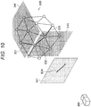
- Fig. 10 is an explanatory view for explaining an example of the polygon mesh correction method according to Variation 1.
- the information processing apparatus 100 extracts candidate points of the feature line from the polygon mesh on the basis of the geometrical feature map so as to specify the feature line. Note that, in the example illustrated in Fig. 10 , the series of sides E21, E22 and E23 corresponds to the feature line of the polygon mesh D20.
- the information processing apparatus 100 calculates a circle having a predetermined radius r centered at the position spaced a predetermined distance ⁇ in a direction perpendicular to the line segment E24 from the middle point of the line segment E24 corresponding to the feature line on the geometrical feature map D21. Furthermore, the information processing apparatus 100 calculates a normal vector of each pixel (i.e., pixel of the geometrical feature map D21) in the calculated circle. Next, the information processing apparatus 100 projects the pixels in the calculated circle to the polygon mesh D20 and calculates vertices in the circle projected on the polygon mesh D20.
- the information processing apparatus 100 calculates an approximate plane on the basis of the calculated normal and vertices. Note that two approximate planes are calculated with respect to one feature line.
- reference characters D41 and D43 schematically indicate approximate planes calculated with respect to features line corresponding to the series of sides E21, E22 and E23.
- the information processing apparatus 100 projects the vertices on the feature line of the polygon mesh D20 to the approximate planes D41 and D43, and corrects the positions of the vertices on the basis of the results of the projection.
- the information processing apparatus 100 executes the aforementioned processing on each of the approximate planes calculated with respect to each feature line to correct the polygon mesh D20.
- a boundary between two approximate planes calculated with respect to one feature line is estimated to correspond to a boundary of mutually adjacent two surfaces among the actual outer surfaces of the real object, which is a target of shape estimation.
- Variation 2 another example of the polygon mesh correction method is described.
- a description is given of an example of the method in which a feature line on the polygon mesh corresponding to sides on the geometrical feature map is specified, and the feature line is used to correct the polygon mesh.
- a description is given of an example of a method in which vertices on the polygon mesh corresponding to endpoints of a side on the geometrical feature map are specified as feature points, and the feature points are used to correct the polygon mesh.
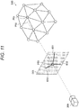
- Fig. 11 and Fig. 12 are explanatory views for explaining an example of the polygon mesh correction method according to Variation 2.
- the information processing apparatus 100 extracts a feature point by projecting endpoints of line segments indicated on the geometrical feature map onto the polygon mesh depending on the capture position corresponding to the geometrical feature map.
- reference character P53 indicates an endpoint of sides E51, E52 and E53 on the geometrical feature map D21.
- the information processing apparatus 100 extends a straight line connecting the capture position 200 and the endpoint P53 to the polygon mesh D20, and calculates a point P55 at which the straight line crosses the polygon mesh D20. Next, the information processing apparatus 100 extracts a vertex positioned in the vicinity of the point P55 among the vertices constituting the polygon mesh D20, as a feature point P51.
- the information processing apparatus 100 specifies a surface including the extracted feature point among the surfaces constituting the polygon mesh and projects the center of gravity of the specified surface onto the normal map.
- reference character c k indicates the center of gravity of a surface including feature point P51.
- reference character P57 indicates a projection point on the normal map D23 on which the center of gravity c k is projected. Note that the method for calculating the projection point P57 is similar to that of the example described above with reference to (Formula 1), and therefore a detailed description is omitted.
- the information processing apparatus 100 estimates the normal vector at the projection point u calculated on the normal map, as an ideal normal of the surface of the polygon mesh D20 corresponding to the center of gravity c k, which is the origin for projection of the projection point u.
- the reference character n k schematically indicates an ideal normal of the surface corresponding to the center of gravity c k.
- the information processing apparatus 100 calculates an ideal normal with respect to each surface including the feature point P51, shifts the positions of at least some vertices of the vertices of the polygon mesh D20 on the basis of the results of the calculation of the ideal normal, and corrects the polygon mesh D20.
- the information processing apparatus 100 may shift the feature point to position p calculated by minimizing the aforementioned (Formula 2).
- T indicates a cluster of surfaces including the feature point.
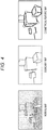
- Fig. 13 is a function block diagram illustrating a configuration example of a hardware configuration of an information processing apparatus constituting an information processing system according to an embodiment of the present disclosure.
- An information processing apparatus 900 constituting the information processing system according to the present embodiment mainly includes a CPU 901, a ROM 902, and a RAM 903. Moreover, the information processing apparatus 900 further includes a host bus 907, a bridge 909, an external bus 911, an interface 913, an input apparatus 915, an output apparatus 917, a storage apparatus 919, a drive 921, a connection port 923, and a communication apparatus 925.
- the CPU 901 functions as an arithmetic processing apparatus and a control apparatus, and controls general or partial operation in the information processing apparatus 900 according to various programs recorded on the ROM 902, the RAM 903, the storage apparatus 919, or a removable recording medium 927.
- the ROM 902 stores a program, an arithmetic parameter, or the like the CPU 901 uses.
- the RAM 903 primarily stores a program used by the CPU 901, a parameter that is properly changed by execution of the program, or the like. These are mutually connected by the host bus 907 including an internal bus, e.g., a CPU bus.
- the CPU 901 can include the depth estimation unit 101, the attitude estimation unit 103, the three-dimensional space model integration unit 105, the normal estimation unit 109, the geometrical feature extraction unit 111, and the correction unit 113, illustrated in Fig. 3 .
- the host bus 907 is connected to an external bus 911, e.g., a peripheral component interconnect/interface (PCI) bus, via the bridge 909. Furthermore, the input apparatus 915, the output apparatus 917, the storage apparatus 919, the drive 921, the connection port 923, and the communication apparatus 925 are connected to the external bus 911 via the interface 913.
- PCI peripheral component interconnect/interface
- the input apparatus 915 is an operation means operated by a user, e.g., a mouse, a keyboard, a touch panel, a button, a switch, a lever, a pedal, or the like. Furthermore, the input apparatus 915 may, for example, be a remote control means (so-called, a remote controller) that uses an infrared ray or other radio waves or may be external connection equipment 929, e.g., a mobile phone or a PDA, corresponding to operations of the information processing apparatus 900. Moreover, the input apparatus 915 includes, for example, an input control circuit and the like that generate an input signal on the basis of information input by the user using the aforementioned operation means and output the input signal to the CPU 901. The user of the information processing apparatus 900 is capable of inputting a variety of data to the information processing apparatus 900 and giving an instruction of processing operation by operating the input apparatus 915.
- the output apparatus 917 includes an apparatus that can visually and aurally notify the user of the acquired information.
- Such an apparatus includes, for example, a display apparatus including a CRT display apparatus, a liquid crystal display apparatus, a plasma display apparatus, an EL display apparatus, a lamp, and the like; an audio output apparatus including a speaker, a headphone, and the like; and a printer apparatus.
- the output apparatus 917 outputs, for example, a result obtained by a variety of processing performed by the information processing apparatus 900.
- the display apparatus displays the result obtained by a variety of processing performed by the information processing apparatus 900 as a text or an image.
- the audio output apparatus converts an audio signal including reproduced audio data, acoustic data, or the like to an analog signal and outputs the signal.
- the storage apparatus 919 is a data storage apparatus configured as an example of the storage unit of the information processing apparatus 900.
- the storage apparatus 919 includes, for example, a magnetic storage unit device, e.g., hard disk drive (HDD), a semiconductor storage device, an optical storage device, or a magneto-optical storage device.
- the storage apparatus 919 stores a program executed by the CPU 901, various data, or the like.
- the storage unit 107 illustrated in Fig. 3 can include the storage apparatus 919.
- the drive 921 is a recording medium reader/writer, and is internally or externally mounted on the information processing apparatus 900.
- the drive 921 reads information recorded on the mounted removable recording medium 927, e.g., a magnetic disk, an optical disk, a magneto-optical disk, or a semiconductor memory, and outputs the information to the RAM 903. Furthermore, the drive 921 can write record on the mounted removable recording medium 927, e.g., the magnetic disk, the optical disk, the magneto-optical disk, or the semiconductor memory.
- the removable recording medium 927 is, for example, a DVD medium, an HD-DVD medium, a Blu-ray (registered trademark) medium, or the like.
- the removable recording medium 927 may be a CompactFlash (CF) (registered trademark), a flash memory, a secure digital memory card (SD memory card), or the like. Furthermore, the removable recording medium 927 may be, for example, an integrated circuit card (IC card) including a non-contact type IC chip, electronic equipment, or the like.
- CF CompactFlash
- SD memory card secure digital memory card
- the removable recording medium 927 may be, for example, an integrated circuit card (IC card) including a non-contact type IC chip, electronic equipment, or the like.
- the connection port 923 is a port for direct connection to the information processing apparatus 900.
- Examples of the connection port 923 include a universal serial bus (USB) port, an IEEE1394 port, a small computer system interface (SCSI) port, and the like.
- Other examples of the connection port 923 include an RS-232C port, an optical audio terminal, a high-definition multimedia interface (HDMI) (registered trademark) port, and the like.
- HDMI high-definition multimedia interface
- the communication apparatus 925 is, for example, a communication interface including a communication device for connection to a communication network (network) 931.
- the communication apparatus 925 is a communication card or the like for, for example, a wired or wireless local area network (LAN), Bluetooth (registered trademark), or wireless USB (WUSB).
- the communication apparatus 925 may be an optical communication router, an asymmetric digital subscriber line (ADSL) router, a model for various communications, or the like.
- the communication apparatus 925 can, for example, transmit and receive a signal and the like with respect to the Internet and other communication equipment in accordance with a predetermined protocol, e.g., TCP/IP.
- the communication network 931 connected to the communication apparatus 925 includes a network connected by wire or wirelessly and the like, and may be, for example, the Internet, home LAN, infrared communication, radio wave communication, satellite communication, or the like.
- the hardware configuration that can achieve the function of the information processing apparatus 900 constituting the information processing system according to an embodiment of the present disclosure is indicated.
- the aforementioned configuration elements may be configured by using general members or may be configured by hardware specialized in the functions of the configuration elements. Accordingly, depending on technological level at the time of carrying out the present embodiment, the hardware configuration to be used can be properly changed. Note that, although not illustrated in Fig. 13 , various configurations corresponding to the information processing apparatus 900 constituting the information processing system are of course included.
- a computer program for achieving the functions of the information processing apparatus 900 constituting the aforementioned the information processing system according to the present embodiment can be produced and mounted on a personal computer or the like. Furthermore, it is also possible to provide a recording medium that stores such a computer program and can be read by a computer.
- the recording medium is, for example, a magnetic disk, an optical disk, a magneto-optical disk, a flash memory, or the like.
- the aforementioned computer program may be, for example, distributed via a network without use of the recording medium.
- the number of computers that execute the computer program is not particularly limited. For example, the computer program may be executed by a plurality of computers (e.g., a plurality of servers or the like) cooperating with each other.
- the information processing apparatus 100 corrects the information (e.g., three-dimensionally shaped model such as polygon mesh) regarding the results of the estimation of the shape of the object (real object) on the real space on the basis of the information (e.g., geometrical feature map) regarding the results of the estimation of the geometrical feature of the object.
- the information processing apparatus 100 separately estimates a geometrical feature of a part where the influence of an error, noise, or the like that occurs during measurement of the distance, e.g., a part corresponding to an edge or a corner of the object, by using a polarization image. Then, the information processing apparatus 100 corrects the results of the estimation of the part corresponding to the edge or the corner among the results of the estimation of the shape of the object depending on the results of the estimation of the geometrical feature of the part corresponding to the edge or the corner.
- the information processing apparatus 100 corrects the information (e.g., three-dimensionally shaped model such as polygon mesh) regarding the results of the estimation of the shape of the object (
- the information processing system 1 according to the present embodiment in a case where the shape of the object is reproduced as a three-dimensionally shaped model or the like, the reproducibility of the shape can be further increased. Furthermore, the information processing system 1 according to the present embodiment can estimate the geometrical feature of the object without depending on the fineness of division of space regarding the estimation of the shape of the object. Therefore, the information processing system 1 according to the present embodiment enables both an increase in reproducibility (particularly, reproducibility of edge or corner part) of the three-dimensionally shaped model and suppression of an increase in data amount for reproduction of the three-dimensional shape.
Claims (4)
- Informationsverarbeitungseinrichtung (100), die Folgendes umfasst:eine Erfassungseinheit, ausgelegt zum Erfassen erster Informationen, die mit einem Ergebnis einer Schätzung einer Form eines Objekts in einem realen Raum assoziiert sind, und zweiter Informationen, die mit einem Ergebnis einer Schätzung eines geometrischen Merkmals des Objekts assoziiert sind; undeine Korrektureinheit (113), ausgelegt zum Korrigieren der ersten Informationen auf einer Basis der zweiten Informationen, wobeidie zweiten Informationen ein Ergebnis einer Schätzung einer Grenze benachbarter Flächen unter äußeren Flächen des Objekts beinhalten,die Grenze auf einer Basis einer Normalenkarte geschätzt wird, auf der eine Verteilung von Normalenvektoren der äußeren Flächen kartiert ist, wobei die Normalenkarte durch einen Sensor in einer Erfassungsposition (200) erzeugt wird,die ersten Informationen Informationen beinhalten, die mit einem Ergebnis einer Schätzung zumindest einiger Flächen der äußeren Flächen assoziiert sind, das Mesh-Daten beinhaltet, die eine Fläche mit mehreren Eckpunkten und die mehreren Eckpunkte verbindenden Seiten spezifizieren,die Korrektureinheit (113) ausgelegt ist zum Korrigieren von Positionen zumindest einiger Eckpunkte unter den mehreren Eckpunkten, um die ersten Informationen auf einer Basis der zweiten Informationen zu korrigieren;dadurch gekennzeichnet, dass entwederdie Korrektureinheit (113) ausgelegt ist zum Projizieren eines Ergebnisses einer Schätzung der Grenze und zweier Endpunkte der Grenze auf die ersten Informationen auf einer Basis der zweiten Informationen, um eine oder mehrere der Seiten zu spezifizieren, die zwei der Eckpunkte der mehreren Eckpunkte verbinden, wobei die zwei Eckpunkte den zwei Endpunkten der Grenze entsprechen,Projizieren eines Schwerpunkts einer oder mehrerer Flächen, die zumindest einige Seiten der einen oder der mehreren spezifizierten Seiten beinhalten, auf die Normalenkarte, um eine ideale Normale der einen oder der mehreren Flächen abhängig von dem Normalenvektor an einem Punkt der Normalenkarte, auf den der Schwerpunkt projiziert wird, zu schätzen, undKorrigieren einer Position mindestens eines Eckpunkts, der an dem Ende der einen oder der mehreren der spezifizierten Seiten vorliegt, auf einer Basis eines Ergebnisses einer Schätzung der Normalen; oderdie Korrektureinheit (113) ausgelegt ist zum Schätzen einer ungefähren Ebene, die die Grenze beinhaltet, auf einer Basis der zweiten Informationen und Projizieren der ungefähren Ebene auf die ersten Informationen undKorrigieren einer Position zumindest einiger Eckpunkte unter den mehreren Eckpunkten auf einer Basis eines Ergebnisses einer Projektion der ungefähren Ebene; oder die Korrektureinheit (113) ausgelegt ist zumProjizieren eines Ergebnisses einer Schätzung eines Endpunkts der Grenze auf einer Basis der zweiten Informationen auf die ersten Informationen und Spezifizieren des Eckpunkts unter den mehreren Eckpunkten, der einem Punkt entspricht, auf den der Endpunkt projiziert wird,Projizieren eines Schwerpunkts einer oder mehrerer Flächen, die den spezifizierten Eckpunkt beinhalten, auf die Normalenkarte, um eine ideale Normale der einen oder der mehreren Flächen abhängig von dem Normalenvektor an einem Punkt der Normalenkarte, auf den der Schwerpunkt projiziert wird, zu schätzen, und Korrigieren von Positionen zumindest einiger Eckpunkte unter den mehreren Eckpunkten auf einer Basis eines Ergebnisses einer Schätzung der Normalen;wobei jede Projektion von der Positionsbeziehung zwischen der Erfassungsposition (200), der Normalenkarte und der Mesh-Daten abhängt.
- Informationsverarbeitungseinrichtung (100) gemäß Anspruch 1, wobei die Normalenkarte auf einer Basis eines Polarisationsbilds des Objekts auf einer Basis eines Ergebnisses einer Detektion jeder mehrerer Polarisationen, deren Polarisationsrichtungen voneinander verschiedenen sind, erzeugt wird.
- Informationsverarbeitungsverfahren, umfassend, durch einen Computer:Erfassen erster Informationen, die mit einem Ergebnis einer Schätzung einer Form eines Objekts in einem realen Raum assoziiert sind, und zweiter Informationen, die mit einem Ergebnis einer Schätzung eines geometrischen Merkmals des Objekts assoziiert sind; und Korrigieren der ersten Informationen auf einer Basis der zweiten Informationen, wobeidie zweiten Informationen ein Ergebnis einer Schätzung einer Grenze benachbarter Flächen unter äußeren Flächen des Objekts beinhalten,die Grenze auf einer Basis einer Normalenkarte geschätzt wird, auf der eine Verteilung von Normalenvektoren der äußeren Flächen kartiert ist, wobei die Normalenkarte durch einen Sensor in einer Erfassungsposition (200) erzeugt wird,die ersten Informationen Informationen beinhalten, die mit einem Ergebnis einer Schätzung zumindest einiger Flächen der äußeren Flächen assoziiert sind, das Mesh-Daten beinhaltet, die eine Fläche mit mehreren Eckpunkten und die mehreren Eckpunkte verbindenden Seiten spezifizieren,Positionen zumindest einiger Eckpunkte unter den mehreren Eckpunkten korrigiert werden, um die ersten Informationen auf einer Basis der zweiten Informationen zu korrigieren;dadurch gekennzeichnet, dass entwederbeim Korrigieren der ersten Informationen ein Ergebnis einer Schätzung der Grenze und zweier Endpunkte der Grenze auf die ersten Informationen auf einer Basis der zweiten Informationen projiziert werden, um eine oder mehrere der Seiten zu spezifizieren, die zwei der Eckpunkte der mehreren Eckpunkte verbinden, wobei die zwei Eckpunkte den zwei Endpunkten der Grenze entsprechen,ein Schwerpunkt einer oder mehrerer Flächen, die zumindest einige Seiten der einen oder der mehreren spezifizierten Seiten beinhalten, auf die Normalenkarte projiziert wird, um eine ideale Normale der einen oderder mehreren Flächen abhängig von dem Normalenvektor an einem Punkt der Normalenkarte, auf den der Schwerpunkt projiziert wird, zu schätzen, undeine Position mindestens eines Eckpunkts, der an dem Ende der einen oder der mehreren der spezifizierten Seiten vorliegt, auf einer Basis eines Ergebnisses einer Schätzung der Normalen korrigiert wird; oderbeim Korrigieren der ersten Informationen eine ungefähre Ebene, die die Grenze beinhaltet, auf einer Basis der zweiten Informationen geschätzt wird und die ungefähre Ebene auf die ersten Informationen projiziert wird undeine Position zumindest einiger Eckpunkte unter den mehreren Eckpunkten auf einer Basis eines Ergebnisses einer Projektion der ungefähren Ebene korrigiert wird; oderbeim Korrigieren der ersten Informationen ein Ergebnis einer Schätzung eines Endpunkts der Grenze auf einer Basis der zweiten Informationen auf die ersten Informationen projiziert wird und der Eckpunkt unter den mehreren Eckpunkten, der einem Punkt entspricht, auf den der Endpunkt projiziert wird, spezifiziert wird,ein Schwerpunkt einer oder mehrerer Flächen, die den spezifizierten Eckpunkt beinhalten, auf die Normalenkarte projiziert wird, um eine ideale Normale der einen oder der mehreren Flächen abhängig von dem Normalenvektor an einem Punkt der Normalenkarte, auf den der Schwerpunkt projiziert wird, zu schätzen, und Positionen zumindest einiger Eckpunkte unter den mehreren Eckpunkten auf einer Basis eines Ergebnisses einer Schätzung der Normalen korrigiert werden;wobei jede Projektion von der Positionsbeziehung zwischen der Erfassungsposition (200), der Normalenkarte und der Mesh-Daten abhängt.
- Programm, das Anweisungen umfasst, die bei Ausführung des Programms durch einen Computer bewirken, dass der Computer das Verfahren nach Anspruch 3 ausführt.
Applications Claiming Priority (2)
| Application Number | Priority Date | Filing Date | Title |
|---|---|---|---|
| JP2017100739A JP2018195241A (ja) | 2017-05-22 | 2017-05-22 | 情報処理装置、情報処理方法、及びプログラム |
| PCT/JP2018/012015 WO2018216341A1 (ja) | 2017-05-22 | 2018-03-26 | 情報処理装置、情報処理方法、及びプログラム |
Publications (3)
| Publication Number | Publication Date |
|---|---|
| EP3633606A1 EP3633606A1 (de) | 2020-04-08 |
| EP3633606A4 EP3633606A4 (de) | 2020-05-27 |
| EP3633606B1 true EP3633606B1 (de) | 2021-08-25 |
Family
ID=64396659
Family Applications (1)
| Application Number | Title | Priority Date | Filing Date |
|---|---|---|---|
| EP18806471.1A Active EP3633606B1 (de) | 2017-05-22 | 2018-03-26 | Informationsverarbeitungsvorrichtung, informationsverarbeitungsverfahren und programm |
Country Status (4)
| Country | Link |
|---|---|
| US (1) | US11488354B2 (de) |
| EP (1) | EP3633606B1 (de) |
| JP (1) | JP2018195241A (de) |
| WO (1) | WO2018216341A1 (de) |
Families Citing this family (6)
| Publication number | Priority date | Publication date | Assignee | Title |
|---|---|---|---|---|
| JP7241546B2 (ja) * | 2019-01-16 | 2023-03-17 | 三菱電機株式会社 | 三次元再構成装置、三次元再構成システム、三次元再構成方法、及び三次元再構成プログラム |
| WO2020208976A1 (ja) * | 2019-04-08 | 2020-10-15 | ソニー株式会社 | 画像処理装置、および画像処理方法、並びにプログラム |
| JP2022021027A (ja) * | 2020-07-21 | 2022-02-02 | ソニーグループ株式会社 | 情報処理装置、情報処理方法、及びコンピュータが読み取り可能な記録媒体 |
| JP7439006B2 (ja) * | 2021-03-18 | 2024-02-27 | 株式会社東芝 | 距離推定装置及び距離推定方法 |
| JP2023038826A (ja) * | 2021-09-07 | 2023-03-17 | トヨタ自動車株式会社 | 傷害推定システム、傷害推定方法、及び傷害推定プログラム |
| WO2023047653A1 (ja) * | 2021-09-27 | 2023-03-30 | ソニーセミコンダクタソリューションズ株式会社 | 情報処理装置、情報処理方法 |
Family Cites Families (11)
| Publication number | Priority date | Publication date | Assignee | Title |
|---|---|---|---|---|
| JPH06176107A (ja) | 1992-12-04 | 1994-06-24 | Canon Inc | 距離画像処理方法及び装置 |
| DE69328230T2 (de) | 1992-12-01 | 2000-08-10 | Canon Kk | Entfernungbildverarbeitungsvorrichtung und -verfahren |
| GB2381429B (en) * | 2001-09-28 | 2005-07-27 | Canon Europa Nv | 3D computer model processing apparatus |
| US8737721B2 (en) * | 2008-05-07 | 2014-05-27 | Microsoft Corporation | Procedural authoring |
| US8760517B2 (en) * | 2010-09-27 | 2014-06-24 | Apple Inc. | Polarized images for security |
| WO2015006224A1 (en) * | 2013-07-08 | 2015-01-15 | Vangogh Imaging, Inc. | Real-time 3d computer vision processing engine for object recognition, reconstruction, and analysis |
| JP2015114307A (ja) * | 2013-12-16 | 2015-06-22 | ソニー株式会社 | 画像処理装置と画像処理方法および撮像装置 |
| JP6426968B2 (ja) | 2014-10-08 | 2018-11-21 | キヤノン株式会社 | 情報処理装置およびその方法 |
| US10260866B2 (en) * | 2015-03-06 | 2019-04-16 | Massachusetts Institute Of Technology | Methods and apparatus for enhancing depth maps with polarization cues |
| JP6488203B2 (ja) | 2015-07-01 | 2019-03-20 | 株式会社ソニー・インタラクティブエンタテインメント | 画像処理装置、画像処理システム、多視点カメラ、および画像処理方法 |
| CN110168608B (zh) * | 2016-11-22 | 2023-08-29 | 乐高公司 | 用于获取物理对象的3维数字表示的系统 |
-
2017
- 2017-05-22 JP JP2017100739A patent/JP2018195241A/ja active Pending
-
2018
- 2018-03-26 WO PCT/JP2018/012015 patent/WO2018216341A1/ja active Application Filing
- 2018-03-26 EP EP18806471.1A patent/EP3633606B1/de active Active
- 2018-03-26 US US16/490,151 patent/US11488354B2/en active Active
Non-Patent Citations (1)
| Title |
|---|
| None * |
Also Published As
| Publication number | Publication date |
|---|---|
| EP3633606A4 (de) | 2020-05-27 |
| US20210407189A1 (en) | 2021-12-30 |
| WO2018216341A1 (ja) | 2018-11-29 |
| EP3633606A1 (de) | 2020-04-08 |
| US11488354B2 (en) | 2022-11-01 |
| JP2018195241A (ja) | 2018-12-06 |
Similar Documents
| Publication | Publication Date | Title |
|---|---|---|
| EP3633606B1 (de) | Informationsverarbeitungsvorrichtung, informationsverarbeitungsverfahren und programm | |
| CN110322500B (zh) | 即时定位与地图构建的优化方法及装置、介质和电子设备 | |
| JP5248806B2 (ja) | 情報処理装置、情報処理方法 | |
| EP2992508B1 (de) | Verminderte und vermittelte realitätseinflüsse aus rekonstruktion | |
| WO2018119889A1 (zh) | 三维场景定位方法和装置 | |
| WO2017217411A1 (ja) | 画像処理装置、画像処理方法、及び記憶媒体 | |
| US20180018805A1 (en) | Three dimensional scene reconstruction based on contextual analysis | |
| JP2011253376A (ja) | 画像処理装置、および画像処理方法、並びにプログラム | |
| CN108648194B (zh) | 基于cad模型三维目标识别分割和位姿测量方法及装置 | |
| JP7103357B2 (ja) | 情報処理装置、情報処理方法、及びプログラム | |
| JPWO2018235163A1 (ja) | キャリブレーション装置、キャリブレーション用チャート、チャートパターン生成装置、およびキャリブレーション方法 | |
| CN112686877B (zh) | 基于双目相机的三维房屋损伤模型构建测量方法及系统 | |
| US20150199572A1 (en) | Object tracking using occluding contours | |
| JP2017182695A (ja) | 情報処理プログラム、情報処理方法および情報処理装置 | |
| CN110349212B (zh) | 即时定位与地图构建的优化方法及装置、介质和电子设备 | |
| JP6584208B2 (ja) | 情報処理装置、情報処理方法、プログラム | |
| KR100951309B1 (ko) | 광학식 모션 캡처 장비를 위한 다중 카메라 보정 방법 | |
| JP2004235934A (ja) | キャリブレーション処理装置、およびキャリブレーション処理方法、並びにコンピュータ・プログラム | |
| JP2017092756A (ja) | 画像処理装置、画像処理方法、画像投影システムおよびプログラム | |
| EP2800055A1 (de) | Verfahren und System zur Erzeugung eines 3D-Modells | |
| JP2011155412A (ja) | 投影システムおよび投影システムにおける歪み修正方法 | |
| TW201523510A (zh) | 點雲拼接系統及方法 | |
| WO2020092051A1 (en) | Rolling shutter rectification in images/videos using convolutional neural networks with applications to sfm/slam with rolling shutter images/videos | |
| JP2018173882A (ja) | 情報処理装置、方法、及びプログラム | |
| JP7121936B2 (ja) | カメラ校正情報取得装置、画像処理装置、カメラ校正情報取得方法およびプログラム |
Legal Events
| Date | Code | Title | Description |
|---|---|---|---|
| STAA | Information on the status of an ep patent application or granted ep patent |
Free format text: STATUS: THE INTERNATIONAL PUBLICATION HAS BEEN MADE |
|
| PUAI | Public reference made under article 153(3) epc to a published international application that has entered the european phase |
Free format text: ORIGINAL CODE: 0009012 |
|
| STAA | Information on the status of an ep patent application or granted ep patent |
Free format text: STATUS: REQUEST FOR EXAMINATION WAS MADE |
|
| 17P | Request for examination filed |
Effective date: 20190821 |
|
| AK | Designated contracting states |
Kind code of ref document: A1 Designated state(s): AL AT BE BG CH CY CZ DE DK EE ES FI FR GB GR HR HU IE IS IT LI LT LU LV MC MK MT NL NO PL PT RO RS SE SI SK SM TR |
|
| AX | Request for extension of the european patent |
Extension state: BA ME |
|
| REG | Reference to a national code |
Ref country code: DE Ref legal event code: R079 Ref document number: 602018022554 Country of ref document: DE Free format text: PREVIOUS MAIN CLASS: G06T0007000000 Ipc: G06T0017000000 |
|
| A4 | Supplementary search report drawn up and despatched |
Effective date: 20200429 |
|
| RIC1 | Information provided on ipc code assigned before grant |
Ipc: G06T 7/00 20170101ALI20200422BHEP Ipc: G06T 17/00 20060101AFI20200422BHEP Ipc: G06T 7/12 20170101ALI20200422BHEP Ipc: G06T 7/50 20170101ALI20200422BHEP Ipc: G01B 11/245 20060101ALI20200422BHEP |
|
| DAV | Request for validation of the european patent (deleted) | ||
| DAX | Request for extension of the european patent (deleted) | ||
| STAA | Information on the status of an ep patent application or granted ep patent |
Free format text: STATUS: EXAMINATION IS IN PROGRESS |
|
| 17Q | First examination report despatched |
Effective date: 20201202 |
|
| GRAP | Despatch of communication of intention to grant a patent |
Free format text: ORIGINAL CODE: EPIDOSNIGR1 |
|
| STAA | Information on the status of an ep patent application or granted ep patent |
Free format text: STATUS: GRANT OF PATENT IS INTENDED |
|
| INTG | Intention to grant announced |
Effective date: 20210317 |
|
| GRAS | Grant fee paid |
Free format text: ORIGINAL CODE: EPIDOSNIGR3 |
|
| GRAA | (expected) grant |
Free format text: ORIGINAL CODE: 0009210 |
|
| STAA | Information on the status of an ep patent application or granted ep patent |
Free format text: STATUS: THE PATENT HAS BEEN GRANTED |
|
| RAP3 | Party data changed (applicant data changed or rights of an application transferred) |
Owner name: SONY GROUP CORPORATION |
|
| AK | Designated contracting states |
Kind code of ref document: B1 Designated state(s): AL AT BE BG CH CY CZ DE DK EE ES FI FR GB GR HR HU IE IS IT LI LT LU LV MC MK MT NL NO PL PT RO RS SE SI SK SM TR |
|
| REG | Reference to a national code |
Ref country code: CH Ref legal event code: EP |
|
| REG | Reference to a national code |
Ref country code: IE Ref legal event code: FG4D Ref country code: AT Ref legal event code: REF Ref document number: 1424565 Country of ref document: AT Kind code of ref document: T Effective date: 20210915 |
|
| REG | Reference to a national code |
Ref country code: DE Ref legal event code: R096 Ref document number: 602018022554 Country of ref document: DE |
|
| REG | Reference to a national code |
Ref country code: LT Ref legal event code: MG9D |
|
| REG | Reference to a national code |
Ref country code: NL Ref legal event code: MP Effective date: 20210825 |
|
| REG | Reference to a national code |
Ref country code: AT Ref legal event code: MK05 Ref document number: 1424565 Country of ref document: AT Kind code of ref document: T Effective date: 20210825 |
|
| PG25 | Lapsed in a contracting state [announced via postgrant information from national office to epo] |
Ref country code: LT Free format text: LAPSE BECAUSE OF FAILURE TO SUBMIT A TRANSLATION OF THE DESCRIPTION OR TO PAY THE FEE WITHIN THE PRESCRIBED TIME-LIMIT Effective date: 20210825 Ref country code: AT Free format text: LAPSE BECAUSE OF FAILURE TO SUBMIT A TRANSLATION OF THE DESCRIPTION OR TO PAY THE FEE WITHIN THE PRESCRIBED TIME-LIMIT Effective date: 20210825 Ref country code: BG Free format text: LAPSE BECAUSE OF FAILURE TO SUBMIT A TRANSLATION OF THE DESCRIPTION OR TO PAY THE FEE WITHIN THE PRESCRIBED TIME-LIMIT Effective date: 20211125 Ref country code: HR Free format text: LAPSE BECAUSE OF FAILURE TO SUBMIT A TRANSLATION OF THE DESCRIPTION OR TO PAY THE FEE WITHIN THE PRESCRIBED TIME-LIMIT Effective date: 20210825 Ref country code: PT Free format text: LAPSE BECAUSE OF FAILURE TO SUBMIT A TRANSLATION OF THE DESCRIPTION OR TO PAY THE FEE WITHIN THE PRESCRIBED TIME-LIMIT Effective date: 20211227 Ref country code: NO Free format text: LAPSE BECAUSE OF FAILURE TO SUBMIT A TRANSLATION OF THE DESCRIPTION OR TO PAY THE FEE WITHIN THE PRESCRIBED TIME-LIMIT Effective date: 20211125 Ref country code: ES Free format text: LAPSE BECAUSE OF FAILURE TO SUBMIT A TRANSLATION OF THE DESCRIPTION OR TO PAY THE FEE WITHIN THE PRESCRIBED TIME-LIMIT Effective date: 20210825 Ref country code: FI Free format text: LAPSE BECAUSE OF FAILURE TO SUBMIT A TRANSLATION OF THE DESCRIPTION OR TO PAY THE FEE WITHIN THE PRESCRIBED TIME-LIMIT Effective date: 20210825 Ref country code: RS Free format text: LAPSE BECAUSE OF FAILURE TO SUBMIT A TRANSLATION OF THE DESCRIPTION OR TO PAY THE FEE WITHIN THE PRESCRIBED TIME-LIMIT Effective date: 20210825 Ref country code: SE Free format text: LAPSE BECAUSE OF FAILURE TO SUBMIT A TRANSLATION OF THE DESCRIPTION OR TO PAY THE FEE WITHIN THE PRESCRIBED TIME-LIMIT Effective date: 20210825 |
|
| PG25 | Lapsed in a contracting state [announced via postgrant information from national office to epo] |
Ref country code: PL Free format text: LAPSE BECAUSE OF FAILURE TO SUBMIT A TRANSLATION OF THE DESCRIPTION OR TO PAY THE FEE WITHIN THE PRESCRIBED TIME-LIMIT Effective date: 20210825 Ref country code: LV Free format text: LAPSE BECAUSE OF FAILURE TO SUBMIT A TRANSLATION OF THE DESCRIPTION OR TO PAY THE FEE WITHIN THE PRESCRIBED TIME-LIMIT Effective date: 20210825 Ref country code: GR Free format text: LAPSE BECAUSE OF FAILURE TO SUBMIT A TRANSLATION OF THE DESCRIPTION OR TO PAY THE FEE WITHIN THE PRESCRIBED TIME-LIMIT Effective date: 20211126 |
|
| PG25 | Lapsed in a contracting state [announced via postgrant information from national office to epo] |
Ref country code: NL Free format text: LAPSE BECAUSE OF FAILURE TO SUBMIT A TRANSLATION OF THE DESCRIPTION OR TO PAY THE FEE WITHIN THE PRESCRIBED TIME-LIMIT Effective date: 20210825 |
|
| PG25 | Lapsed in a contracting state [announced via postgrant information from national office to epo] |
Ref country code: DK Free format text: LAPSE BECAUSE OF FAILURE TO SUBMIT A TRANSLATION OF THE DESCRIPTION OR TO PAY THE FEE WITHIN THE PRESCRIBED TIME-LIMIT Effective date: 20210825 |
|
| REG | Reference to a national code |
Ref country code: DE Ref legal event code: R097 Ref document number: 602018022554 Country of ref document: DE |
|
| PG25 | Lapsed in a contracting state [announced via postgrant information from national office to epo] |
Ref country code: SM Free format text: LAPSE BECAUSE OF FAILURE TO SUBMIT A TRANSLATION OF THE DESCRIPTION OR TO PAY THE FEE WITHIN THE PRESCRIBED TIME-LIMIT Effective date: 20210825 Ref country code: SK Free format text: LAPSE BECAUSE OF FAILURE TO SUBMIT A TRANSLATION OF THE DESCRIPTION OR TO PAY THE FEE WITHIN THE PRESCRIBED TIME-LIMIT Effective date: 20210825 Ref country code: RO Free format text: LAPSE BECAUSE OF FAILURE TO SUBMIT A TRANSLATION OF THE DESCRIPTION OR TO PAY THE FEE WITHIN THE PRESCRIBED TIME-LIMIT Effective date: 20210825 Ref country code: EE Free format text: LAPSE BECAUSE OF FAILURE TO SUBMIT A TRANSLATION OF THE DESCRIPTION OR TO PAY THE FEE WITHIN THE PRESCRIBED TIME-LIMIT Effective date: 20210825 Ref country code: CZ Free format text: LAPSE BECAUSE OF FAILURE TO SUBMIT A TRANSLATION OF THE DESCRIPTION OR TO PAY THE FEE WITHIN THE PRESCRIBED TIME-LIMIT Effective date: 20210825 Ref country code: AL Free format text: LAPSE BECAUSE OF FAILURE TO SUBMIT A TRANSLATION OF THE DESCRIPTION OR TO PAY THE FEE WITHIN THE PRESCRIBED TIME-LIMIT Effective date: 20210825 |
|
| PLBE | No opposition filed within time limit |
Free format text: ORIGINAL CODE: 0009261 |
|
| STAA | Information on the status of an ep patent application or granted ep patent |
Free format text: STATUS: NO OPPOSITION FILED WITHIN TIME LIMIT |
|
| PG25 | Lapsed in a contracting state [announced via postgrant information from national office to epo] |
Ref country code: IT Free format text: LAPSE BECAUSE OF FAILURE TO SUBMIT A TRANSLATION OF THE DESCRIPTION OR TO PAY THE FEE WITHIN THE PRESCRIBED TIME-LIMIT Effective date: 20210825 |
|
| 26N | No opposition filed |
Effective date: 20220527 |
|
| PG25 | Lapsed in a contracting state [announced via postgrant information from national office to epo] |
Ref country code: SI Free format text: LAPSE BECAUSE OF FAILURE TO SUBMIT A TRANSLATION OF THE DESCRIPTION OR TO PAY THE FEE WITHIN THE PRESCRIBED TIME-LIMIT Effective date: 20210825 |
|
| PG25 | Lapsed in a contracting state [announced via postgrant information from national office to epo] |
Ref country code: MC Free format text: LAPSE BECAUSE OF FAILURE TO SUBMIT A TRANSLATION OF THE DESCRIPTION OR TO PAY THE FEE WITHIN THE PRESCRIBED TIME-LIMIT Effective date: 20210825 |
|
| REG | Reference to a national code |
Ref country code: CH Ref legal event code: PL |
|
| REG | Reference to a national code |
Ref country code: BE Ref legal event code: MM Effective date: 20220331 |
|
| PG25 | Lapsed in a contracting state [announced via postgrant information from national office to epo] |
Ref country code: LU Free format text: LAPSE BECAUSE OF NON-PAYMENT OF DUE FEES Effective date: 20220326 Ref country code: LI Free format text: LAPSE BECAUSE OF NON-PAYMENT OF DUE FEES Effective date: 20220331 Ref country code: IE Free format text: LAPSE BECAUSE OF NON-PAYMENT OF DUE FEES Effective date: 20220326 Ref country code: FR Free format text: LAPSE BECAUSE OF NON-PAYMENT OF DUE FEES Effective date: 20220331 Ref country code: CH Free format text: LAPSE BECAUSE OF NON-PAYMENT OF DUE FEES Effective date: 20220331 |
|
| PG25 | Lapsed in a contracting state [announced via postgrant information from national office to epo] |
Ref country code: BE Free format text: LAPSE BECAUSE OF NON-PAYMENT OF DUE FEES Effective date: 20220331 |
|
| PGFP | Annual fee paid to national office [announced via postgrant information from national office to epo] |
Ref country code: GB Payment date: 20230222 Year of fee payment: 6 Ref country code: DE Payment date: 20230221 Year of fee payment: 6 |
|
| P01 | Opt-out of the competence of the unified patent court (upc) registered |
Effective date: 20230528 |