EP3633390B1 - Method and device for detecting faults of a sensor - Google Patents
Method and device for detecting faults of a sensor Download PDFInfo
- Publication number
- EP3633390B1 EP3633390B1 EP19188538.3A EP19188538A EP3633390B1 EP 3633390 B1 EP3633390 B1 EP 3633390B1 EP 19188538 A EP19188538 A EP 19188538A EP 3633390 B1 EP3633390 B1 EP 3633390B1
- Authority
- EP
- European Patent Office
- Prior art keywords
- sensor
- computing unit
- time constant
- discharge
- discharge time
- Prior art date
- Legal status (The legal status is an assumption and is not a legal conclusion. Google has not performed a legal analysis and makes no representation as to the accuracy of the status listed.)
- Active
Links
- 238000000034 method Methods 0.000 title claims description 22
- 238000005259 measurement Methods 0.000 claims description 31
- 238000011156 evaluation Methods 0.000 claims description 11
- 238000001914 filtration Methods 0.000 claims description 10
- 238000011157 data evaluation Methods 0.000 claims description 9
- 238000012545 processing Methods 0.000 claims description 9
- 239000011159 matrix material Substances 0.000 claims description 6
- 230000036962 time dependent Effects 0.000 claims description 6
- 238000012544 monitoring process Methods 0.000 claims description 4
- 238000012806 monitoring device Methods 0.000 claims description 3
- 238000001514 detection method Methods 0.000 claims description 2
- 238000013500 data storage Methods 0.000 claims 2
- 230000006870 function Effects 0.000 description 18
- 230000015572 biosynthetic process Effects 0.000 description 14
- 230000001133 acceleration Effects 0.000 description 8
- 230000007257 malfunction Effects 0.000 description 5
- 238000010586 diagram Methods 0.000 description 4
- 238000012423 maintenance Methods 0.000 description 3
- 239000003990 capacitor Substances 0.000 description 2
- 238000003745 diagnosis Methods 0.000 description 2
- 238000002405 diagnostic procedure Methods 0.000 description 2
- 238000007599 discharging Methods 0.000 description 2
- 230000004044 response Effects 0.000 description 2
- 238000013459 approach Methods 0.000 description 1
- 230000007547 defect Effects 0.000 description 1
- 230000005611 electricity Effects 0.000 description 1
- 230000004807 localization Effects 0.000 description 1
- 239000000725 suspension Substances 0.000 description 1
- 230000009466 transformation Effects 0.000 description 1
- 230000001052 transient effect Effects 0.000 description 1
Images

Classifications
-
- G—PHYSICS
- G01—MEASURING; TESTING
- G01P—MEASURING LINEAR OR ANGULAR SPEED, ACCELERATION, DECELERATION, OR SHOCK; INDICATING PRESENCE, ABSENCE, OR DIRECTION, OF MOVEMENT
- G01P21/00—Testing or calibrating of apparatus or devices covered by the preceding groups
-
- B—PERFORMING OPERATIONS; TRANSPORTING
- B61—RAILWAYS
- B61K—AUXILIARY EQUIPMENT SPECIALLY ADAPTED FOR RAILWAYS, NOT OTHERWISE PROVIDED FOR
- B61K9/00—Railway vehicle profile gauges; Detecting or indicating overheating of components; Apparatus on locomotives or cars to indicate bad track sections; General design of track recording vehicles
- B61K9/02—Profile gauges, e.g. loading gauges
-
- G—PHYSICS
- G01—MEASURING; TESTING
- G01M—TESTING STATIC OR DYNAMIC BALANCE OF MACHINES OR STRUCTURES; TESTING OF STRUCTURES OR APPARATUS, NOT OTHERWISE PROVIDED FOR
- G01M17/00—Testing of vehicles
- G01M17/08—Railway vehicles
-
- G—PHYSICS
- G01—MEASURING; TESTING
- G01P—MEASURING LINEAR OR ANGULAR SPEED, ACCELERATION, DECELERATION, OR SHOCK; INDICATING PRESENCE, ABSENCE, OR DIRECTION, OF MOVEMENT
- G01P15/00—Measuring acceleration; Measuring deceleration; Measuring shock, i.e. sudden change of acceleration
- G01P15/02—Measuring acceleration; Measuring deceleration; Measuring shock, i.e. sudden change of acceleration by making use of inertia forces using solid seismic masses
- G01P15/08—Measuring acceleration; Measuring deceleration; Measuring shock, i.e. sudden change of acceleration by making use of inertia forces using solid seismic masses with conversion into electric or magnetic values
- G01P15/09—Measuring acceleration; Measuring deceleration; Measuring shock, i.e. sudden change of acceleration by making use of inertia forces using solid seismic masses with conversion into electric or magnetic values by piezoelectric pick-up
-
- H—ELECTRICITY
- H10—SEMICONDUCTOR DEVICES; ELECTRIC SOLID-STATE DEVICES NOT OTHERWISE PROVIDED FOR
- H10N—ELECTRIC SOLID-STATE DEVICES NOT OTHERWISE PROVIDED FOR
- H10N30/00—Piezoelectric or electrostrictive devices
- H10N30/80—Constructional details
- H10N30/802—Drive or control circuitry or methods for piezoelectric or electrostrictive devices not otherwise provided for
-
- H—ELECTRICITY
- H10—SEMICONDUCTOR DEVICES; ELECTRIC SOLID-STATE DEVICES NOT OTHERWISE PROVIDED FOR
- H10N—ELECTRIC SOLID-STATE DEVICES NOT OTHERWISE PROVIDED FOR
- H10N30/00—Piezoelectric or electrostrictive devices
- H10N30/30—Piezoelectric or electrostrictive devices with mechanical input and electrical output, e.g. functioning as generators or sensors
- H10N30/302—Sensors
Definitions
- the invention relates to a method for detecting faults in a sensor, in particular a piezoelectric sensor for vehicles, measurements being carried out using the sensor, discharge time data with a first discharge time constant of the sensor being read out from a data memory of the sensor and corresponding measurement signals as well as the discharge time.
- Data are transmitted to a computing unit, with signal processing, signal evaluation and data evaluation taking place in the computing unit and with parameter values of a time-dependent discharge function being determined with respect to the sensor, a second discharge time constant being determined from the discharge function and by comparing the first discharge time constant with the second discharge time constant Malfunctions, errors or damage to the sensor are detected.
- Vehicles such as rail vehicles, must have a high level of driving safety. An accurate assessment and prediction of the technical conditions of vehicles, chassis and other vehicle components is therefore important.
- a diagnostic device for a rail vehicle is known from the prior art WO 2014/048768 A1 shown, with acceleration sensors and an electronic diagnostic device arranged on a chassis being provided. Corresponding diagnoses of the chassis are made on the basis of acceleration measurements, which are evaluated in the diagnostic device.
- High quality and a low error rate of measurements are important for vehicle diagnostics. In particular, it is necessary that measurement errors due to interference, Damage to sensors etc. can be detected and incorrect measured values can be excluded from diagnostic processes or the influence of the interference on the measurements can be reduced.
- DE 10 2011 106 302 B3 known, in which a method for detecting measurement errors from sensors is described. Using a calibration process, sensor values are first determined, forces and/or moments are determined using inversion of a measurement matrix, and pseudosensor values are then calculated using inverse transformation of the forces and/or moments. The sensor values are compared with the pseudosensor values in order to detect a possible measurement error.
- the JP 2001 209444 A describes a power supply device for a capacitor with a voltmeter, which measures voltages at two points in time. With the measured two voltage values as well as the two points in time and a charge and discharge characteristic of the capacitor, a time constant is determined with which a remaining charging or discharging period can be determined.
- a passive sensor is disclosed, which is set up to determine localization errors based on a mean square deviation.
- the DE 10 2012 217721 A1 shows a diagnostic device for a rail vehicle with acceleration sensors.
- the invention is therefore based on the object of specifying a method that has been further developed compared to the prior art and which enables precise detection of sensor faults while taking into account sensor properties.
- this object is achieved with a method of the type mentioned at the outset, in which filtered signals are formed by filtering the measurement signals, the parameter values of the time-dependent discharge function comprising a time matrix with a first time, a second time up to an N time by means of logarithmization filtered signals can be determined.
- the method is based on an evaluation of sensor properties, namely the first discharge time constant and the second discharge time constant. Sensor faults are therefore detected with great certainty, which means their influence on the measurements can be reduced.
- the malfunction can be visualized, for example, on a display unit in a driver's cab of the vehicle or in a maintenance stand. This measure enables a rapid response to the disruption. For example This means that a sensor replacement can be prepared in good time by triggering the procurement of spare parts.
- the method according to the invention is implemented, for example, in a diagnostic and monitoring device of a vehicle and the sensor monitors a vehicle component (e.g. a damper, a wheel, a spring device, etc.), this measure ensures high reliability and availability of a corresponding monitoring and diagnostic method with regard to this vehicle component.
- a vehicle component e.g. a damper, a wheel, a spring device, etc.
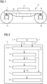
- Fig. 1 shows a chassis 13 of a vehicle designed as a rail vehicle.
- the chassis 13 includes a primary suspension chassis frame 14, which is connected to a first wheelset 15 and a second wheelset 16 and on which a secondary spring device 17 is arranged.
- the chassis 13 is connected to a car body, not shown.
- a sensor 1 is provided on the chassis frame 14 in an area above the first wheelset 15. Furthermore, a computing unit 4 is arranged on the chassis frame 14 and is connected to the sensor 1 via a line 18. However, according to the invention, it is also conceivable that the computing unit 4 is provided, for example, in the car body of the vehicle and the sensor 1 is connected to the computing unit 4 via corresponding line paths between the chassis 13 and the car body.
- the sensor 1, the computing unit 4 and the line 18 form a diagnostic and monitoring device of the rail vehicle, by means of which accelerations of the chassis frame 14 are evaluated and defects in vehicle components (e.g. on a damper) are determined based on evaluated acceleration information.
- the sensor 1 is supplied with electricity via the computing unit 4 and the line 18. Data is also transmitted between the sensor 1 and the computing unit 4 via the line 18.
- the computing unit 4 is connected to a vehicle on-board power network and a vehicle on-board data bus, which are not shown.
- FIG. 2 schematically, shown as a flow chart, exemplary embodiment variant of an inventive,
- the partially computer-implemented method is implemented in a vehicle (not shown) designed as a rail vehicle.
- a sensor 1 which is also in Fig. 1 shown and designed as a piezoelectric sensor 1 (integrated circuit piezoelectric sensor, ie ICP sensor), also carries out measurements 2 of accelerations of a Fig. 1 shown chassis frame 14.
- Corresponding measurement signals 3 are transmitted via an in Fig. 1 Line 18 shown to a also in Fig. 1 Computing unit 4 shown is transmitted.
- discharge time data which include a first discharge time constant ⁇ 1 of the sensor 1 are read out via the computing unit 4 from a transducer electronic data sheet (TEDS) of a data memory of the sensor 1, that is to say via the line 18 from the sensor 1 to the computing unit 4 transmitted.
- TMS transducer electronic data sheet
- signal processing 5 and signal evaluation 6 take place with regard to the measurement signals 3, with acceleration information regarding the chassis frame 14 being extracted from the measurement signals 3.
- a data evaluation 7 is carried out, via which the mentioned first discharge time constant ⁇ 1 is extracted from the discharge time data.
- filtering 8 of the measurement signals 3 takes place as bandpass filtering, with filtered signals 9 being formed from the measurement signals 3.
- Absolute amounts of the filtered signals 9 are converted into parameter values of a discharge function b - with respect to the sensor 1 using logarithmization 10.
- the measurements 2, the signal processing 5, the signal evaluation 6, the data evaluation 7, the filtering 8 and the logarithmization 10 are carried out continuously while the vehicle is operating at a frequency of 10 Hz, although lower or higher frequencies are of course also conceivable.
- the first formation rule y 1 has a constant C, a time t and a second discharge time constant ⁇ 2 and describes a discharging process of the sensor 1.
- the parameter values correspond to function values of the second formation rule y 2 .
- the discharge time constant formation 12 and the comparison 11 are continuous with a frequency of 10 Hz carried out, whereby smaller or larger frequencies can of course also be set.
- the measurements 2 on the one hand and the signal processing 5, the signal evaluation 6, the data evaluation 7, the filtering 8, the logarithmization 10, the discharge time constant formation 12 and the comparison 11 on the other hand are carried out with different frequencies.
- a malfunction, an error or damage to the sensor 1 is detected when a difference between the first discharge time constant ⁇ 1 and the second discharge time constant ⁇ 2 falls below a defined first limit value and when a root of a mean sum of squares error, ie a root mean square error ( RSME) of the second discharge time constant ⁇ 2 falls below a defined second limit value.
- RSME root mean square error
- a warning event or a warning signal is generated (warning event generation 19).
- This is done by the computing unit 4 via a connection Fig. 1 Vehicle on-board data bus described is routed to a driver's cab of the vehicle and displayed on a display unit.
- it is also possible to transmit the warning signal or information regarding the first discharge time constant ⁇ 1 and the second discharge time constant ⁇ 2 etc., ie diagnostic and monitoring signals regarding the sensor 1, via a vehicle antenna connected to the computing unit 4 and arranged on a roof of the vehicle by radio to a maintenance stand with a corresponding receiving unit for further evaluation on a maintenance computer, whereby a diagnosis or a remaining service life forecast of the sensor 1 is carried out.
- Fig. 3 is one related to Fig. 2 described exponential first formation rule y 1 as the basis of a also in connection with Fig. 2 disclosed discharge function b - of a sensor 1 is shown as a first diagram.
- Times t are plotted on an abscissa of the first diagram, and on an ordinate in connection with Fig. 2 9 extracted function values from the filtered signals mentioned.
- Fig. 4 is one related to Fig. 2 described linear second formation rule y 2 for a also in connection with Fig. 2 disclosed discharge function b - of a sensor 1 shown as a second diagram.
- Times t are plotted on an abscissa of the second diagram, and on an ordinate from in connection with Fig. 2 Function values formed from the filtered signals 9 mentioned using logarithmization 10. The function values correspond in connection with Fig. 2 described parameter values of the discharge function b - .
Description
Die Erfindung bezieht sich auf ein Verfahren zur Detektion von Störungen eines Sensors, insbesondere eines piezoelektrischen Sensors für Fahrzeuge, wobei mittels des Sensors Messungen durchgeführt, aus einem Datenspeicher des Sensors Entladezeit-Daten mit einer ersten Entladezeitkonstante des Sensors ausgelesen und entsprechende Messsignale sowie die Entladezeit-Daten an eine Recheneinheit übermittelt werden, wobei in der Recheneinheit eine Signalverarbeitung, eine Signalauswertung sowie eine Datenauswertung erfolgt und wobei Parameterwerte einer zeitabhängigen Entladefunktion bezüglich des Sensors ermittelt werden, aus der Entladefunktion eine zweite Entladezeitkonstante bestimmt wird und mittels Vergleich der ersten Entladezeitkonstante mit der zweiten Entladezeitkonstante Störungen, Fehler oder Schäden des Sensors detektiert werden.The invention relates to a method for detecting faults in a sensor, in particular a piezoelectric sensor for vehicles, measurements being carried out using the sensor, discharge time data with a first discharge time constant of the sensor being read out from a data memory of the sensor and corresponding measurement signals as well as the discharge time. Data are transmitted to a computing unit, with signal processing, signal evaluation and data evaluation taking place in the computing unit and with parameter values of a time-dependent discharge function being determined with respect to the sensor, a second discharge time constant being determined from the discharge function and by comparing the first discharge time constant with the second discharge time constant Malfunctions, errors or damage to the sensor are detected.
Fahrzeuge, beispielsweise Schienenfahrzeuge, müssen eine hohe Fahrsicherheit aufweisen. Eine genaue Einschätzung und Vorhersage von technischen Zuständen von Fahrzeugen, Fahrwerken und weiteren Fahrzeugkomponenten ist daher wichtig.Vehicles, such as rail vehicles, must have a high level of driving safety. An accurate assessment and prediction of the technical conditions of vehicles, chassis and other vehicle components is therefore important.
Eine Diagnoseeinrichtung für ein Schienenfahrzeug ist in der aus dem Stand der Technik bekannten
Eine hohe Qualität sowie eine geringe Fehlerrate von Messungen sind für Fahrzeugdiagnosen wichtig. Insbesondere ist es erforderlich, dass Messfehler aufgrund von Störungen, Beschädigungen von Sensoren etc. erkannt und fehlerhafte Messwerte aus Diagnosevorgängen ausgeschlossen oder Einflüsse der Störungen auf die Messungen reduziert werden können.High quality and a low error rate of measurements are important for vehicle diagnostics. In particular, it is necessary that measurement errors due to interference, Damage to sensors etc. can be detected and incorrect measured values can be excluded from diagnostic processes or the influence of the interference on the measurements can be reduced.
Aus dem Stand der Technik ist hierzu beispielsweise die
Dieser Ansatz weist in seiner bekannten Form den Nachteil auf, dass die Messfehler bzw. Störungen der Sensoren nur indirekt, d.h. mittels der Sensorwerte und der Pseudosensorwerte, erfasst werden.In its known form, this approach has the disadvantage that the measurement errors or disturbances in the sensors are only recorded indirectly, i.e. by means of the sensor values and the pseudosensor values.
Weiterhin sind in der
Die
In der
Die
Ferner ist in der
Der Erfindung liegt daher die Aufgabe zugrunde, ein gegenüber dem Stand der Technik weiterentwickeltes Verfahren anzugeben, welches eine genaue Detektion von Sensorstörungen unter Einbeziehung von Sensoreigenschaften ermöglicht.The invention is therefore based on the object of specifying a method that has been further developed compared to the prior art and which enables precise detection of sensor faults while taking into account sensor properties.
Erfindungsgemäß wird diese Aufgabe gelöst mit einem Verfahren der eingangs genannten Art, bei dem mittels Filterung der Messsignale gefilterte Signale gebildet werden, wobei die Parameterwerte der zeitabhängigen Entladefunktion umfassend eine Zeitmatrix mit einer ersten Zeit, einer zweiten Zeit bis zu einer N-Zeit mittels Logarithmierung der gefilterten Signale ermittelt werden.According to the invention, this object is achieved with a method of the type mentioned at the outset, in which filtered signals are formed by filtering the measurement signals, the parameter values of the time-dependent discharge function comprising a time matrix with a first time, a second time up to an N time by means of logarithmization filtered signals can be determined.
Dadurch wird eine Überwachung des Sensors und somit ein hohes Sicherheitsniveau sowie eine hohe Verfügbarkeit im Betrieb des Sensors bewirkt und eine Diagnose des Sensors ermöglicht.This results in monitoring of the sensor and thus a high level of security as well as high availability in the operation of the sensor and enables diagnosis of the sensor.
Das Verfahren basiert auf einer Auswertung von Sensoreigenschaften, nämlich der ersten Entladezeitkonstante und der zweiten Entladezeitkonstante. Störungen des Sensors werden daher mit großer Sicherheit erkannt, wodurch deren Einflüsse auf die Messungen reduziert werden können.The method is based on an evaluation of sensor properties, namely the first discharge time constant and the second discharge time constant. Sensor faults are therefore detected with great certainty, which means their influence on the measurements can be reduced.
Es ist günstig, wenn bei Detektion einer Störung, eines Fehlers oder eines Schadens des Sensors ein Warnereignis erzeugt wird.It is advantageous if a warning event is generated when a fault, error or damage to the sensor is detected.
Eine Visualisierung der Störung kann beispielsweise auf einer Anzeigeeinheit in einem Führerstand des Fahrzeugs oder in einem Wartungsstand erfolgen. Durch diese Maßnahme wird eine rasche Reaktion auf die Störung ermöglicht. Beispielsweise kann dadurch ein Sensortausch durch Auslösung einer Ersatzteilbeschaffung rechtzeitig vorbereitet werden.The malfunction can be visualized, for example, on a display unit in a driver's cab of the vehicle or in a maintenance stand. This measure enables a rapid response to the disruption. For example This means that a sensor replacement can be prepared in good time by triggering the procurement of spare parts.
Eine vorteilhafte Ausgestaltung erhält man, wenn die Messungen, die Signalverarbeitung, die Signalauswertung, die Datenauswertung, die Filterung, die Logarithmierung, eine Entladezeitkonstanten-Bildung und der Vergleich kontinuierlich durchgeführt werden.An advantageous embodiment is obtained if the measurements, the signal processing, the signal evaluation, the data evaluation, the filtering, the logarithmization, a discharge time constant formation and the comparison are carried out continuously.
Ist das erfindungsgemäße Verfahren beispielsweise in ein Diagnose- und Überwachungsgerät eines Fahrzeugs implementiert und überwacht der Sensor eine Fahrzeugkomponente (z.B. einen Dämpfer, ein Rad, eine Federvorrichtung etc.), so wird durch diese Maßnahme eine hohe Zuverlässigkeit und Verfügbarkeit eines entsprechenden Überwachungs- und Diagnoseverfahrens bezüglich dieser Fahrzeugkomponente bewirkt.If the method according to the invention is implemented, for example, in a diagnostic and monitoring device of a vehicle and the sensor monitors a vehicle component (e.g. a damper, a wheel, a spring device, etc.), this measure ensures high reliability and availability of a corresponding monitoring and diagnostic method with regard to this vehicle component.
Auf dem Fahrwerksrahmen 14 ist in einem Bereich über dem ersten Radsatz 15 ein Sensor 1 vorgesehen. Weiterhin ist auf dem Fahrwerksrahmen 14 eine Recheneinheit 4 angeordnet, welche über eine Leitung 18 mit dem Sensor 1 verbunden ist. Erfindungsgemäß ist es jedoch auch denkbar, dass die Recheneinheit 4 beispielsweise in dem Wagenkasten des Fahrzeugs vorgesehen ist und der Sensor 1 über entsprechende Leitungswege zwischen dem Fahrwerk 13 und dem Wagenkasten mit der Recheneinheit 4 verbunden ist.A sensor 1 is provided on the
Der Sensor 1, die Recheneinheit 4 und die Leitung 18 bilden ein Diagnose- und Überwachungsgerät des Schienenfahrzeugs, mittels dessen Beschleunigungen des Fahrwerksrahmens 14 ausgewertet und anhand ausgewerteter Beschleunigungsinformationen Defekte an Fahrzeugkomponenten (z.B. an einem Dämpfer) festgestellt werden.The sensor 1, the
Der Sensor 1 ist über die Recheneinheit 4 sowie die Leitung 18 mit Elektrizität versorgt. Über die Leitung 18 erfolgt weiterhin auch eine Datenübertragung zwischen dem Sensor 1 und der Recheneinheit 4.The sensor 1 is supplied with electricity via the
Die Recheneinheit 4 ist mit einem Fahrzeug-Bordstromnetz sowie einem Fahrzeug-Borddatenbus, welche nicht dargestellt sind, verbunden.The
Mittels des Sensors 1 sowie der Recheneinheit 4 wird eine im Zusammenhang mit
Eine in
Ein Sensor 1, welcher auch in
Weiterhin werden über die Recheneinheit 4 aus einem Transducer Electronic Data Sheet (TEDS) eines Datenspeichers des Sensors 1 Entladezeit-Daten, welche eine erste Entladezeitkonstante τ 1 des Sensors 1 umfassen, ausgelesen, d.h. über die Leitung 18 von dem Sensor 1 an die Recheneinheit 4 übertragen.Furthermore, discharge time data, which include a first discharge time constant τ 1 of the sensor 1, are read out via the
In der Recheneinheit 4 erfolgt eine Signalverarbeitung 5 und eine Signalauswertung 6 bezüglich der Messsignale 3, wobei Beschleunigungsinformationen bezüglich des Fahrwerksrahmens 14 aus den Messsignalen 3 extrahiert werden.In the
Weiterhin wird eine Datenauswertung 7 durchgeführt, über welche die genannte erste Entladezeitkonstante τ 1 aus den Entladezeit-Daten extrahiert wird.Furthermore, a
Weiterhin erfolgt eine als Bandpassfilterung ausgeführte Filterung 8 der Messsignale 3, wobei aus den Messsignalen 3 gefilterte Signale 9 gebildet werden.Furthermore, filtering 8 of the
Absolutbeträge der gefilterten Signale 9 werden mittels Logarithmierung 10 in Parameterwerte einer Entladefunktion b- bezüglich des Sensors 1 übergeführt.Absolute amounts of the filtered signals 9 are converted into parameter values of a discharge function b - with respect to the sensor 1 using
Die Messungen 2, die Signalverarbeitung 5, die Signalauswertung 6, die Datenauswertung 7, die Filterung 8 und die Logarithmierung 10 werden kontinuierlich während eines Betriebs des Fahrzeugs mit einer Frequenz von 10 Hz durchgeführt, wobei selbstverständlich auch geringere oder höhere Frequenzen denkbar sind.The measurements 2, the signal processing 5, the signal evaluation 6, the
Demnach wird mittels der beispielhaften Ausführungsvariante eines erfindungsgemäßen Verfahrens eine Vielzahl von Parameterwerten für die Entladefunktion b- gebildet.Accordingly, a large number of parameter values for the discharge function b - are formed by means of the exemplary embodiment variant of a method according to the invention.
Die Entladefunktion b- basiert auf einer exponentiellen ersten Bildungsvorschrift y1 mit ![]()
![]()
Die erste Bildungsvorschrift y1 weist eine Konstante C, eine Zeit t sowie eine zweite Entladezeitkonstante τ2 auf und beschreibt einen Entladungsvorgang des Sensors 1. Eine auf der ersten Bildungsvorschrift y1 basierende, lineare zweite Bildungsvorschrift y2 lautet wie folgt: ![]()
![]()
Die zweite Bildungsvorschrift y2 weist eine Steigung k mit ![]()
![]()
Die vektorwertige, zeitabhängige Entladefunktion b- mit einer ersten Komponente b1 und einer zweiten Komponente b2 ist aus der zweiten Bildungsvorschrift y2 wie folgt gebildet: 
Die Entladefunktion b- umfasst eine Zeitmatrix X mit einer ersten Zeit t1, einer zweiten Zeit t2 bis zu einer N-Zeit tN, welche wie folgt definiert ist: 
Weiterhin weist die Entladefunktion b- einen Parametervektor y- mit einem ersten Parameterwert y21, einem zweiten Parameterwert y22 bis zu einem N-Parameterwert y2N, welche mit der ersten Zeit t1, der zweiten Zeit t2 bis zu der N-Zeit tN korrelieren und aus den gefilterten Signalen 9 gebildet werden, auf, welcher folgendermaßen definiert ist: 
Die Parameterwerte entsprechen Funktionswerten der zweiten Bildungsvorschrift y2.The parameter values correspond to function values of the second formation rule y 2 .
Aus der Entladefunktion b- wird die Steigung k und aus der Steigung k die zweite Entladezeitkonstante τ2 mittels einer Methode der kleinsten Quadrate, wobei es sich um eine aus dem Stand der Technik bekannte Methode einer Ausgleichungsrechnung handelt, aus folgenden Zusammenhängen bestimmt (Entladezeitkonstanten-Bildung 12): ![]()
![]()
![]()
![]()
Mittels eines Vergleichs 11 der ersten Entladezeitkonstante τ 1 mit der zweiten Entladezeitkonstante τ2 werden ein Einschwingen von Messsignalen 3 und somit Störungen, Fehler oder Schäden des Sensors 1 detektiert.By means of a
Die Entladezeitkonstanten-Bildung 12 und der Vergleich 11 werden kontinuierlich mit einer Frequenz von 10 Hz durchgeführt, wobei natürlich auch kleinere oder größere Frequenzen einstellbar sind.The discharge time
Erfindungsgemäß ist es auch denkbar, dass die Messungen 2 einerseits und die Signalverarbeitung 5, die Signalauswertung 6, die Datenauswertung 7, die Filterung 8, die Logarithmierung 10, die Entladezeitkonstanten-Bildung 12 sowie der Vergleich 11 andererseits mit unterschiedlichen Frequenzen durchgeführt werden.According to the invention, it is also conceivable that the measurements 2 on the one hand and the signal processing 5, the signal evaluation 6, the
Eine Störung, ein Fehler oder ein Schaden des Sensors 1 wird dann detektiert, wenn eine Differenz zwischen der ersten Entladezeitkonstante τ 1 und der zweiten Entladezeitkonstante τ2 einen definierten ersten Grenzwert unterschreitet und wenn eine Wurzel einer mittleren Fehlerquadratsumme, d.h. ein Root Mean Square Error (RSME) der zweiten Entladezeitkonstante τ 2 einen definierten zweiten Grenzwert unterschreitet.A malfunction, an error or damage to the sensor 1 is detected when a difference between the first discharge time constant τ 1 and the second discharge time constant τ 2 falls below a defined first limit value and when a root of a mean sum of squares error, ie a root mean square error ( RSME) of the second discharge time constant τ 2 falls below a defined second limit value.
Wird eine Störung, ein Fehler oder ein Schaden des Sensors 1 festgestellt, so wird ein Warnereignis bzw. ein Warnsignal erzeugt (Warnereignis-Erzeugung 19). Dieses wird von der Recheneinheit 4 über einen im Zusammenhang mit
Weiterhin ist es denkbar, den Sensor 1 nach Feststellung einer Störung, eines Fehlers oder eines Schadens auszuschalten, wofür die Recheneinheit 4 eine Stromversorgung des Sensors 1 über die Leitung 18, welche auch im Zusammenhang mit
In
Auf einer Abszisse des ersten Diagramms sind Zeiten t aufgetragen, auf einer Ordinate aus im Zusammenhang mit
In
Auf einer Abszisse des zweiten Diagramms sind Zeiten t aufgetragen, auf einer Ordinate aus im Zusammenhang mit
- 11
- Sensorsensor
- 22
- MessungMeasurement
- 33
- Messsignalmeasurement signal
- 44
- RecheneinheitComputing unit
- 55
- SignalverarbeitungSignal processing
- 66
- SignalauswertungSignal evaluation
- 77
- DatenauswertungData evaluation
- 88th
- FilterungFiltering
- 99
- Gefiltertes SignalFiltered signal
- 1010
- LogarithmierungLogarithmization
- 1111
- VergleichComparison
- 1212
- Entladezeitkonstanten-BildungDischarge time constant formation
- 1313
- Fahrwerklanding gear
- 1414
- FahrwerksrahmenChassis frame
- 1515
- Erster RadsatzFirst set of wheels
- 1616
- Zweiter RadsatzSecond set of wheels
- 1717
- SekundärfedervorrichtungSecondary spring device
- 1818
- LeitungLine
- 1919
- Warnereignis-ErzeugungWarning event generation
- τ1τ1
- Erste EntladezeitkonstanteFirst discharge time constant
- τ2τ2
- Zweite EntladezeitkonstanteSecond discharge time constant
- b-b-
- EntladefunktionDischarge function
- y1y1
- Erste BildungsvorschriftFirst educational regulation
- y2y2
- Zweite BildungsvorschriftSecond educational regulation
- CC
- Konstanteconstant
- tt
- ZeitTime
- kk
- Steigungpitch
- b1b1
- Erste KomponenteFirst component
- b2b2
- Zweite KomponenteSecond component
- XX
- ZeitmatrixTime matrix
- t1t1
- Erste ZeitFirst time
- t2t2
- Zweite ZeitSecond time
- tNtN
- N-ZeitN time
- y-y-
- ParametervektorParameter vector
- y21y21
- Erster ParameterwertFirst parameter value
- y22y22
- Zweiter ParameterwertSecond parameter value
- y2Ny2N
- N-ParameterwertN parameter value
Claims (12)
- Method for detecting errors of a sensor (1), in particular of a piezoelectric sensor (1) for vehicles, wherein by means of the sensor (1) measurements (2) are taken and corresponding measurement signals (3) are transmitted to a computing unit (4), wherein discharge time data with a first discharge time constant (τ 1) of the sensor is read out from a data storage unit of the sensor (1) and is transmitted to the computing unit (4), wherein a signal processing (5), a signal evaluation (6) and a data evaluation (7) take place in the computing unit (4) and wherein parameter values of a time-dependent discharge function (b-) in relation to the sensor are determined in the computing unit (4), a second discharge time constant (τ 2 ) is determined from the discharge function (b-) and by means of a comparison (11) of the first discharge time constant (τ 1) and the second discharge time constant (τ 2 ) errors, faults or damage of the sensor (1) are detected, characterised in that filtered signals are formed by means of filtering (8) of the measurement signals (3) in the computing unit (4), wherein the parameter values of the time-dependent discharge function (b-), comprising a time matrix (X) with a first time (t1), a second time (t2) up to an N time (tN), are determined by means of a logarithmic function (10) of the filtered signals (9).
- Method according to claim 1, characterised in that the second discharge time constant (τ 2) is determined from a gradient (k) of the discharge function (b).
- Method according to claim 1 or 2, characterised in that a warning event is generated upon detection of an error, a fault or damage of the sensor (1).
- Method according to one of claims 1 to 3, characterised in that the measurements (2), the signal processing (5), the signal evaluation (6), the data evaluation (7), the filtering (8), the logarithmic function (10), a discharge time constant creation (12) and the comparison (11) are performed continuously.
- Method according to one of claims 1 to 4, characterised in that the second discharge time constant (τ 2) is determined by means of an equalisation sum.
- Method according to claim 5, characterised in that an error, a fault or damage of the sensor (1) is detected when a difference between the first discharge time constant (τ 1) and the second discharge time constant (τ 2) falls below a defined first limit value and when a root mean square error of the second discharge time constant (τ 2) falls below a defined second limit value.
- Vehicle configured for performing a method according to one of claims 1 to 6, wherein the sensor (1), comprising the data storage unit, is arranged for carrying out measurements (2) and the computing unit (4) is configured for signal processing (5), for signal evaluation (6) and for data evaluation (7) on the vehicle, wherein the sensor (1) and the computing unit (4) are configured to transmit measurement signals (3) and discharge time data with a first discharge time constant (τ 1) of the sensor (1) to the computing unit (4) and wherein the computing unit (4) is configured for filtering (8) the measurement signals (3), by means of which filtered signals (9) are formed, for performing a logarithmic function (10) on the filtered signals (9), by means of which parameter values of a time-dependent discharge function (b-), comprising a time matrix (X) with a first time (t1), a second time (t2) up to an N time (tN), are determined in relation to the sensor (1), for discharge time constant creation (12), by means of which a second discharge time constant (τ 2 ) is determined from the discharge function (b-), as well as for comparing (11) the first discharge time constant (τ 1) with the second discharge time constant (τ 2 ) to detect errors, faults or damage of the sensor (1).
- Vehicle according to claim 7, characterised in that the sensor (1) and the computing unit (4) are provided on a chassis (13) of the vehicle.
- Vehicle according to claim 7, characterised in that the sensor (1) is provided on a chassis (13) of the vehicle and the computing unit (4) is provided in or on a vehicle body of the vehicle.
- Vehicle according to one of claims 7 to 9, characterised in that the sensor (1) and the computing unit (4) are designed as parts of a diagnostic and monitoring device of the vehicle.
- Vehicle according to one of claims 7 to 10, characterised in that the computing unit (4) is connected to a display unit on which a detected error, a detected fault or a detected damage of the sensor (1) can be displayed.
- Vehicle according to one of claims 7 to 11, characterised in that an antenna arranged on or in the vehicle and connected to the computing unit (4) is provided which is designed for transmitting diagnostic and monitoring signals in relation to the sensor (1).
Applications Claiming Priority (1)
| Application Number | Priority Date | Filing Date | Title |
|---|---|---|---|
| ATA50843/2018A AT521038B1 (en) | 2018-10-02 | 2018-10-02 | Method and device for detecting disturbances of a sensor |
Publications (2)
| Publication Number | Publication Date |
|---|---|
| EP3633390A1 EP3633390A1 (en) | 2020-04-08 |
| EP3633390B1 true EP3633390B1 (en) | 2023-11-15 |
Family
ID=67439043
Family Applications (1)
| Application Number | Title | Priority Date | Filing Date |
|---|---|---|---|
| EP19188538.3A Active EP3633390B1 (en) | 2018-10-02 | 2019-07-26 | Method and device for detecting faults of a sensor |
Country Status (3)
| Country | Link |
|---|---|
| US (1) | US11293939B2 (en) |
| EP (1) | EP3633390B1 (en) |
| AT (1) | AT521038B1 (en) |
Family Cites Families (10)
| Publication number | Priority date | Publication date | Assignee | Title |
|---|---|---|---|---|
| US5506454A (en) * | 1991-03-20 | 1996-04-09 | Hitachi, Ltd. | System and method for diagnosing characteristics of acceleration sensor |
| SE503922C2 (en) * | 1994-11-17 | 1996-09-30 | Lg Products Ab | Measuring line for a coaxial conductor to determine the throughput and standing wave ratio |
| JP4440406B2 (en) * | 2000-01-26 | 2010-03-24 | 宣夫 芦立 | Power supply |
| JP4348862B2 (en) * | 2000-12-22 | 2009-10-21 | 株式会社デンソー | Drive device for piezo actuator |
| DE102008001571A1 (en) * | 2008-05-06 | 2009-11-12 | Robert Bosch Gmbh | Method and device for monitoring a piezoactuator |
| DE102009031182A1 (en) * | 2009-06-29 | 2010-12-30 | Brüel & Kjaer Vibro GmbH | Method for monitoring acceleration sensor with respect to failure or defectiveness for power plant turbine, involves indicating failure or defectiveness of sensor, when preset deviation between signal and reference responses exists |
| DE102011106302B3 (en) | 2011-07-01 | 2012-09-20 | Deutsches Zentrum für Luft- und Raumfahrt e.V. | Method for determining measurement error of force moment sensor utilized in robotics, involves comparing determined sensor values with pseudo sensor values received by inverse transformation for determining measurement error of sensor |
| ITTO20110694A1 (en) * | 2011-07-28 | 2011-10-27 | Torino Politecnico | SYSTEM OF INFOMOBILITY AND / OR SELF-ENHANCED DIAGNOSTICS AND HARVESTER DEVICE PERFECTED FOR SUPPLYING THIS SYSTEM |
| DE102012217721A1 (en) * | 2012-09-28 | 2014-04-03 | Siemens Aktiengesellschaft | Device for a rail vehicle |
| CN104237845B (en) * | 2014-09-19 | 2016-08-24 | 中国电子科技集团公司第二十八研究所 | A kind of passive sensor target location estimation difference mean square analysis method |
-
2018
- 2018-10-02 AT ATA50843/2018A patent/AT521038B1/en active
-
2019
- 2019-07-26 EP EP19188538.3A patent/EP3633390B1/en active Active
- 2019-10-01 US US16/589,777 patent/US11293939B2/en active Active
Also Published As
| Publication number | Publication date |
|---|---|
| EP3633390A1 (en) | 2020-04-08 |
| AT521038B1 (en) | 2019-10-15 |
| US20200103437A1 (en) | 2020-04-02 |
| US11293939B2 (en) | 2022-04-05 |
| AT521038A4 (en) | 2019-10-15 |
Similar Documents
| Publication | Publication Date | Title |
|---|---|---|
| DE102009002682B4 (en) | Device and method for residual evaluation of a residual for detecting system errors in the system behavior of a system of an aircraft | |
| DE102011082806A1 (en) | Method and device for diagnosing faults in components of chassis systems of motor vehicles | |
| WO2019219756A1 (en) | Method and apparatus for diagnosis and monitoring of vehicles, vehicle components and routes | |
| DE60213258T2 (en) | DIAGNOSIS FOR PIEZOELECTRIC SENSOR | |
| DE102017200855A1 (en) | Method and system for diagnosing components of a vehicle | |
| DE102020212277A1 (en) | Method and device for determining a remaining service life based on a predictive diagnosis of components of an electric drive system using artificial intelligence methods | |
| DE102006047262A1 (en) | Method for testing an electronic unit | |
| DE102014117857B4 (en) | Method and system for checking tire pressure | |
| EP3633390B1 (en) | Method and device for detecting faults of a sensor | |
| DE10062602B4 (en) | Method and device for monitoring the behavior of rail vehicles and for diagnosing components of rail vehicles | |
| DE102008049224A1 (en) | Method for monitoring drive mechanism of rail vehicle movable on rail track to identify defect at e.g. rotary stand of chassis, involves detecting component running in certain direction of acceleration of pivot mounting as sensor variable | |
| DE112021005667T5 (en) | Method and device for detecting anomalies in a mechanical device or a mechanical component | |
| DE102018127457A1 (en) | Device and method for monitoring the condition of an electrical machine | |
| DE102013105397B4 (en) | Condition monitoring of a rail vehicle | |
| DE102005030202A1 (en) | Method and device for condition monitoring of ship installations | |
| DE102015214987B4 (en) | Determination of a defective component of a vehicle | |
| DE102017218806A1 (en) | Device for reading operating parameters of a vehicle and corresponding vehicle | |
| DE102014200343A1 (en) | A method of determining increased resistance of a cell connector | |
| DE102016008031A1 (en) | Method and system for testing a chassis of a vehicle | |
| EP3626576A1 (en) | Method and device for diagnosing and monitoring vehicle components | |
| EP3593099B1 (en) | Method for operating an on-board weighing system, and tachograph system comprising a weighing system | |
| WO2020104195A1 (en) | Method and analysis system for determining a state of a diaphragm of an ultrasound sensor | |
| DE102019202428A1 (en) | Method of diagnosis of vibration dampers | |
| AT521732B1 (en) | Process for diagnosing and monitoring vehicle components | |
| DE102019107242A1 (en) | Diagnostic method, diagnostic system and motor vehicle |
Legal Events
| Date | Code | Title | Description |
|---|---|---|---|
| PUAI | Public reference made under article 153(3) epc to a published international application that has entered the european phase |
Free format text: ORIGINAL CODE: 0009012 |
|
| STAA | Information on the status of an ep patent application or granted ep patent |
Free format text: STATUS: THE APPLICATION HAS BEEN PUBLISHED |
|
| AK | Designated contracting states |
Kind code of ref document: A1 Designated state(s): AL AT BE BG CH CY CZ DE DK EE ES FI FR GB GR HR HU IE IS IT LI LT LU LV MC MK MT NL NO PL PT RO RS SE SI SK SM TR |
|
| AX | Request for extension of the european patent |
Extension state: BA ME |
|
| STAA | Information on the status of an ep patent application or granted ep patent |
Free format text: STATUS: REQUEST FOR EXAMINATION WAS MADE |
|
| 17P | Request for examination filed |
Effective date: 20201005 |
|
| RBV | Designated contracting states (corrected) |
Designated state(s): AL AT BE BG CH CY CZ DE DK EE ES FI FR GB GR HR HU IE IS IT LI LT LU LV MC MK MT NL NO PL PT RO RS SE SI SK SM TR |
|
| STAA | Information on the status of an ep patent application or granted ep patent |
Free format text: STATUS: EXAMINATION IS IN PROGRESS |
|
| 17Q | First examination report despatched |
Effective date: 20211004 |
|
| GRAP | Despatch of communication of intention to grant a patent |
Free format text: ORIGINAL CODE: EPIDOSNIGR1 |
|
| STAA | Information on the status of an ep patent application or granted ep patent |
Free format text: STATUS: GRANT OF PATENT IS INTENDED |
|
| INTG | Intention to grant announced |
Effective date: 20230622 |
|
| RIC1 | Information provided on ipc code assigned before grant |
Ipc: H10N 30/80 20230101ALI20230609BHEP Ipc: B61K 9/02 20060101ALI20230609BHEP Ipc: G01P 15/09 20060101ALI20230609BHEP Ipc: G01P 21/00 20060101AFI20230609BHEP |
|
| GRAS | Grant fee paid |
Free format text: ORIGINAL CODE: EPIDOSNIGR3 |
|
| GRAA | (expected) grant |
Free format text: ORIGINAL CODE: 0009210 |
|
| STAA | Information on the status of an ep patent application or granted ep patent |
Free format text: STATUS: THE PATENT HAS BEEN GRANTED |
|
| AK | Designated contracting states |
Kind code of ref document: B1 Designated state(s): AL AT BE BG CH CY CZ DE DK EE ES FI FR GB GR HR HU IE IS IT LI LT LU LV MC MK MT NL NO PL PT RO RS SE SI SK SM TR |
|
| REG | Reference to a national code |
Ref country code: CH Ref legal event code: EP Ref country code: GB Ref legal event code: FG4D Free format text: NOT ENGLISH |
|
| REG | Reference to a national code |
Ref country code: DE Ref legal event code: R096 Ref document number: 502019009907 Country of ref document: DE |
|
| REG | Reference to a national code |
Ref country code: IE Ref legal event code: FG4D Free format text: LANGUAGE OF EP DOCUMENT: GERMAN |
|
| REG | Reference to a national code |
Ref country code: LT Ref legal event code: MG9D |
|
| REG | Reference to a national code |
Ref country code: NL Ref legal event code: MP Effective date: 20231115 |
|
| PG25 | Lapsed in a contracting state [announced via postgrant information from national office to epo] |
Ref country code: GR Free format text: LAPSE BECAUSE OF FAILURE TO SUBMIT A TRANSLATION OF THE DESCRIPTION OR TO PAY THE FEE WITHIN THE PRESCRIBED TIME-LIMIT Effective date: 20240216 |
|
| PG25 | Lapsed in a contracting state [announced via postgrant information from national office to epo] |
Ref country code: IS Free format text: LAPSE BECAUSE OF FAILURE TO SUBMIT A TRANSLATION OF THE DESCRIPTION OR TO PAY THE FEE WITHIN THE PRESCRIBED TIME-LIMIT Effective date: 20240315 |
|
| PG25 | Lapsed in a contracting state [announced via postgrant information from national office to epo] |
Ref country code: LT Free format text: LAPSE BECAUSE OF FAILURE TO SUBMIT A TRANSLATION OF THE DESCRIPTION OR TO PAY THE FEE WITHIN THE PRESCRIBED TIME-LIMIT Effective date: 20231115 |
|
| PG25 | Lapsed in a contracting state [announced via postgrant information from national office to epo] |
Ref country code: NL Free format text: LAPSE BECAUSE OF FAILURE TO SUBMIT A TRANSLATION OF THE DESCRIPTION OR TO PAY THE FEE WITHIN THE PRESCRIBED TIME-LIMIT Effective date: 20231115 |