EP3633304A1 - Standalone regulated thermo-box - Google Patents
Standalone regulated thermo-box Download PDFInfo
- Publication number
- EP3633304A1 EP3633304A1 EP19199574.5A EP19199574A EP3633304A1 EP 3633304 A1 EP3633304 A1 EP 3633304A1 EP 19199574 A EP19199574 A EP 19199574A EP 3633304 A1 EP3633304 A1 EP 3633304A1
- Authority
- EP
- European Patent Office
- Prior art keywords
- phase change
- change material
- air
- housing
- volume
- Prior art date
- Legal status (The legal status is an assumption and is not a legal conclusion. Google has not performed a legal analysis and makes no representation as to the accuracy of the status listed.)
- Granted
Links
- 230000001105 regulatory effect Effects 0.000 title description 5
- 239000012782 phase change material Substances 0.000 claims abstract description 106
- 238000010438 heat treatment Methods 0.000 claims abstract description 23
- 239000011810 insulating material Substances 0.000 claims abstract description 4
- 238000005192 partition Methods 0.000 claims abstract description 4
- 239000004020 conductor Substances 0.000 claims description 12
- 238000005265 energy consumption Methods 0.000 claims description 7
- 239000000523 sample Substances 0.000 claims description 6
- 230000000903 blocking effect Effects 0.000 claims description 5
- 230000008859 change Effects 0.000 description 18
- 230000005855 radiation Effects 0.000 description 14
- 239000000463 material Substances 0.000 description 6
- QGZKDVFQNNGYKY-UHFFFAOYSA-N Ammonia Chemical compound N QGZKDVFQNNGYKY-UHFFFAOYSA-N 0.000 description 4
- 238000001816 cooling Methods 0.000 description 4
- 230000006870 function Effects 0.000 description 4
- 239000000203 mixture Substances 0.000 description 4
- 238000012544 monitoring process Methods 0.000 description 4
- 238000007711 solidification Methods 0.000 description 4
- 230000008023 solidification Effects 0.000 description 4
- 238000012546 transfer Methods 0.000 description 4
- OKTJSMMVPCPJKN-UHFFFAOYSA-N Carbon Chemical compound [C] OKTJSMMVPCPJKN-UHFFFAOYSA-N 0.000 description 3
- 238000004891 communication Methods 0.000 description 3
- 230000000694 effects Effects 0.000 description 3
- 235000021183 entrée Nutrition 0.000 description 3
- 239000007789 gas Substances 0.000 description 3
- 229910002804 graphite Inorganic materials 0.000 description 3
- 239000010439 graphite Substances 0.000 description 3
- 239000007787 solid Substances 0.000 description 3
- 238000009423 ventilation Methods 0.000 description 3
- 230000032683 aging Effects 0.000 description 2
- 230000001276 controlling effect Effects 0.000 description 2
- 230000004927 fusion Effects 0.000 description 2
- 230000006872 improvement Effects 0.000 description 2
- 230000033001 locomotion Effects 0.000 description 2
- 230000002441 reversible effect Effects 0.000 description 2
- 239000000126 substance Substances 0.000 description 2
- 238000004378 air conditioning Methods 0.000 description 1
- 229910021529 ammonia Inorganic materials 0.000 description 1
- 230000008901 benefit Effects 0.000 description 1
- 230000015556 catabolic process Effects 0.000 description 1
- 239000002131 composite material Substances 0.000 description 1
- 230000003247 decreasing effect Effects 0.000 description 1
- 238000006731 degradation reaction Methods 0.000 description 1
- 230000006866 deterioration Effects 0.000 description 1
- 229940079593 drug Drugs 0.000 description 1
- 239000003814 drug Substances 0.000 description 1
- 230000005611 electricity Effects 0.000 description 1
- 235000013305 food Nutrition 0.000 description 1
- 239000002803 fossil fuel Substances 0.000 description 1
- 239000012212 insulator Substances 0.000 description 1
- 239000007788 liquid Substances 0.000 description 1
- 229940127554 medical product Drugs 0.000 description 1
- 238000002844 melting Methods 0.000 description 1
- 230000008018 melting Effects 0.000 description 1
- 238000000034 method Methods 0.000 description 1
- 238000012986 modification Methods 0.000 description 1
- 230000004048 modification Effects 0.000 description 1
- 229910000069 nitrogen hydride Inorganic materials 0.000 description 1
- 230000003287 optical effect Effects 0.000 description 1
- 239000011368 organic material Substances 0.000 description 1
- 238000013021 overheating Methods 0.000 description 1
- 239000012188 paraffin wax Substances 0.000 description 1
- 230000003334 potential effect Effects 0.000 description 1
- 239000000843 powder Substances 0.000 description 1
- 230000001932 seasonal effect Effects 0.000 description 1
- 230000003068 static effect Effects 0.000 description 1
- 229960005486 vaccine Drugs 0.000 description 1
Images


Classifications
-
- F—MECHANICAL ENGINEERING; LIGHTING; HEATING; WEAPONS; BLASTING
- F28—HEAT EXCHANGE IN GENERAL
- F28D—HEAT-EXCHANGE APPARATUS, NOT PROVIDED FOR IN ANOTHER SUBCLASS, IN WHICH THE HEAT-EXCHANGE MEDIA DO NOT COME INTO DIRECT CONTACT
- F28D20/00—Heat storage plants or apparatus in general; Regenerative heat-exchange apparatus not covered by groups F28D17/00 or F28D19/00
- F28D20/02—Heat storage plants or apparatus in general; Regenerative heat-exchange apparatus not covered by groups F28D17/00 or F28D19/00 using latent heat
-
- H—ELECTRICITY
- H01—ELECTRIC ELEMENTS
- H01M—PROCESSES OR MEANS, e.g. BATTERIES, FOR THE DIRECT CONVERSION OF CHEMICAL ENERGY INTO ELECTRICAL ENERGY
- H01M10/00—Secondary cells; Manufacture thereof
- H01M10/60—Heating or cooling; Temperature control
- H01M10/65—Means for temperature control structurally associated with the cells
- H01M10/658—Means for temperature control structurally associated with the cells by thermal insulation or shielding
-
- A—HUMAN NECESSITIES
- A61—MEDICAL OR VETERINARY SCIENCE; HYGIENE
- A61B—DIAGNOSIS; SURGERY; IDENTIFICATION
- A61B50/00—Containers, covers, furniture or holders specially adapted for surgical or diagnostic appliances or instruments, e.g. sterile covers
-
- F—MECHANICAL ENGINEERING; LIGHTING; HEATING; WEAPONS; BLASTING
- F25—REFRIGERATION OR COOLING; COMBINED HEATING AND REFRIGERATION SYSTEMS; HEAT PUMP SYSTEMS; MANUFACTURE OR STORAGE OF ICE; LIQUEFACTION SOLIDIFICATION OF GASES
- F25D—REFRIGERATORS; COLD ROOMS; ICE-BOXES; COOLING OR FREEZING APPARATUS NOT OTHERWISE PROVIDED FOR
- F25D3/00—Devices using other cold materials; Devices using cold-storage bodies
- F25D3/02—Devices using other cold materials; Devices using cold-storage bodies using ice, e.g. ice-boxes
- F25D3/06—Movable containers
- F25D3/08—Movable containers portable, i.e. adapted to be carried personally
-
- H—ELECTRICITY
- H01—ELECTRIC ELEMENTS
- H01M—PROCESSES OR MEANS, e.g. BATTERIES, FOR THE DIRECT CONVERSION OF CHEMICAL ENERGY INTO ELECTRICAL ENERGY
- H01M10/00—Secondary cells; Manufacture thereof
- H01M10/42—Methods or arrangements for servicing or maintenance of secondary cells or secondary half-cells
- H01M10/46—Accumulators structurally combined with charging apparatus
- H01M10/465—Accumulators structurally combined with charging apparatus with solar battery as charging system
-
- H—ELECTRICITY
- H01—ELECTRIC ELEMENTS
- H01M—PROCESSES OR MEANS, e.g. BATTERIES, FOR THE DIRECT CONVERSION OF CHEMICAL ENERGY INTO ELECTRICAL ENERGY
- H01M10/00—Secondary cells; Manufacture thereof
- H01M10/60—Heating or cooling; Temperature control
- H01M10/62—Heating or cooling; Temperature control specially adapted for specific applications
-
- H—ELECTRICITY
- H01—ELECTRIC ELEMENTS
- H01M—PROCESSES OR MEANS, e.g. BATTERIES, FOR THE DIRECT CONVERSION OF CHEMICAL ENERGY INTO ELECTRICAL ENERGY
- H01M10/00—Secondary cells; Manufacture thereof
- H01M10/60—Heating or cooling; Temperature control
- H01M10/65—Means for temperature control structurally associated with the cells
- H01M10/656—Means for temperature control structurally associated with the cells characterised by the type of heat-exchange fluid
- H01M10/6561—Gases
- H01M10/6563—Gases with forced flow, e.g. by blowers
-
- H—ELECTRICITY
- H01—ELECTRIC ELEMENTS
- H01M—PROCESSES OR MEANS, e.g. BATTERIES, FOR THE DIRECT CONVERSION OF CHEMICAL ENERGY INTO ELECTRICAL ENERGY
- H01M10/00—Secondary cells; Manufacture thereof
- H01M10/60—Heating or cooling; Temperature control
- H01M10/65—Means for temperature control structurally associated with the cells
- H01M10/659—Means for temperature control structurally associated with the cells by heat storage or buffering, e.g. heat capacity or liquid-solid phase changes or transition
-
- H—ELECTRICITY
- H01—ELECTRIC ELEMENTS
- H01M—PROCESSES OR MEANS, e.g. BATTERIES, FOR THE DIRECT CONVERSION OF CHEMICAL ENERGY INTO ELECTRICAL ENERGY
- H01M50/00—Constructional details or processes of manufacture of the non-active parts of electrochemical cells other than fuel cells, e.g. hybrid cells
- H01M50/20—Mountings; Secondary casings or frames; Racks, modules or packs; Suspension devices; Shock absorbers; Transport or carrying devices; Holders
- H01M50/202—Casings or frames around the primary casing of a single cell or a single battery
-
- H—ELECTRICITY
- H01—ELECTRIC ELEMENTS
- H01M—PROCESSES OR MEANS, e.g. BATTERIES, FOR THE DIRECT CONVERSION OF CHEMICAL ENERGY INTO ELECTRICAL ENERGY
- H01M50/00—Constructional details or processes of manufacture of the non-active parts of electrochemical cells other than fuel cells, e.g. hybrid cells
- H01M50/20—Mountings; Secondary casings or frames; Racks, modules or packs; Suspension devices; Shock absorbers; Transport or carrying devices; Holders
- H01M50/218—Mountings; Secondary casings or frames; Racks, modules or packs; Suspension devices; Shock absorbers; Transport or carrying devices; Holders characterised by the material
- H01M50/22—Mountings; Secondary casings or frames; Racks, modules or packs; Suspension devices; Shock absorbers; Transport or carrying devices; Holders characterised by the material of the casings or racks
- H01M50/231—Mountings; Secondary casings or frames; Racks, modules or packs; Suspension devices; Shock absorbers; Transport or carrying devices; Holders characterised by the material of the casings or racks having a layered structure
-
- A—HUMAN NECESSITIES
- A61—MEDICAL OR VETERINARY SCIENCE; HYGIENE
- A61B—DIAGNOSIS; SURGERY; IDENTIFICATION
- A61B50/00—Containers, covers, furniture or holders specially adapted for surgical or diagnostic appliances or instruments, e.g. sterile covers
- A61B2050/001—Temperature-modifying means
-
- A—HUMAN NECESSITIES
- A61—MEDICAL OR VETERINARY SCIENCE; HYGIENE
- A61J—CONTAINERS SPECIALLY ADAPTED FOR MEDICAL OR PHARMACEUTICAL PURPOSES; DEVICES OR METHODS SPECIALLY ADAPTED FOR BRINGING PHARMACEUTICAL PRODUCTS INTO PARTICULAR PHYSICAL OR ADMINISTERING FORMS; DEVICES FOR ADMINISTERING FOOD OR MEDICINES ORALLY; BABY COMFORTERS; DEVICES FOR RECEIVING SPITTLE
- A61J1/00—Containers specially adapted for medical or pharmaceutical purposes
- A61J1/14—Details; Accessories therefor
- A61J1/16—Holders for containers
-
- A—HUMAN NECESSITIES
- A61—MEDICAL OR VETERINARY SCIENCE; HYGIENE
- A61J—CONTAINERS SPECIALLY ADAPTED FOR MEDICAL OR PHARMACEUTICAL PURPOSES; DEVICES OR METHODS SPECIALLY ADAPTED FOR BRINGING PHARMACEUTICAL PRODUCTS INTO PARTICULAR PHYSICAL OR ADMINISTERING FORMS; DEVICES FOR ADMINISTERING FOOD OR MEDICINES ORALLY; BABY COMFORTERS; DEVICES FOR RECEIVING SPITTLE
- A61J2200/00—General characteristics or adaptations
- A61J2200/40—Heating or cooling means; Combinations thereof
-
- A—HUMAN NECESSITIES
- A61—MEDICAL OR VETERINARY SCIENCE; HYGIENE
- A61N—ELECTROTHERAPY; MAGNETOTHERAPY; RADIATION THERAPY; ULTRASOUND THERAPY
- A61N1/00—Electrotherapy; Circuits therefor
- A61N1/18—Applying electric currents by contact electrodes
- A61N1/32—Applying electric currents by contact electrodes alternating or intermittent currents
- A61N1/38—Applying electric currents by contact electrodes alternating or intermittent currents for producing shock effects
- A61N1/39—Heart defibrillators
- A61N1/3904—External heart defibrillators [EHD]
-
- A—HUMAN NECESSITIES
- A61—MEDICAL OR VETERINARY SCIENCE; HYGIENE
- A61N—ELECTROTHERAPY; MAGNETOTHERAPY; RADIATION THERAPY; ULTRASOUND THERAPY
- A61N1/00—Electrotherapy; Circuits therefor
- A61N1/18—Applying electric currents by contact electrodes
- A61N1/32—Applying electric currents by contact electrodes alternating or intermittent currents
- A61N1/38—Applying electric currents by contact electrodes alternating or intermittent currents for producing shock effects
- A61N1/39—Heart defibrillators
- A61N1/3968—Constructional arrangements, e.g. casings
-
- F—MECHANICAL ENGINEERING; LIGHTING; HEATING; WEAPONS; BLASTING
- F28—HEAT EXCHANGE IN GENERAL
- F28D—HEAT-EXCHANGE APPARATUS, NOT PROVIDED FOR IN ANOTHER SUBCLASS, IN WHICH THE HEAT-EXCHANGE MEDIA DO NOT COME INTO DIRECT CONTACT
- F28D21/00—Heat-exchange apparatus not covered by any of the groups F28D1/00 - F28D20/00
- F28D2021/0019—Other heat exchangers for particular applications; Heat exchange systems not otherwise provided for
- F28D2021/0028—Other heat exchangers for particular applications; Heat exchange systems not otherwise provided for for cooling heat generating elements, e.g. for cooling electronic components or electric devices
-
- F—MECHANICAL ENGINEERING; LIGHTING; HEATING; WEAPONS; BLASTING
- F28—HEAT EXCHANGE IN GENERAL
- F28D—HEAT-EXCHANGE APPARATUS, NOT PROVIDED FOR IN ANOTHER SUBCLASS, IN WHICH THE HEAT-EXCHANGE MEDIA DO NOT COME INTO DIRECT CONTACT
- F28D21/00—Heat-exchange apparatus not covered by any of the groups F28D1/00 - F28D20/00
- F28D2021/0019—Other heat exchangers for particular applications; Heat exchange systems not otherwise provided for
- F28D2021/0077—Other heat exchangers for particular applications; Heat exchange systems not otherwise provided for for tempering, e.g. with cooling or heating circuits for temperature control of elements
-
- Y—GENERAL TAGGING OF NEW TECHNOLOGICAL DEVELOPMENTS; GENERAL TAGGING OF CROSS-SECTIONAL TECHNOLOGIES SPANNING OVER SEVERAL SECTIONS OF THE IPC; TECHNICAL SUBJECTS COVERED BY FORMER USPC CROSS-REFERENCE ART COLLECTIONS [XRACs] AND DIGESTS
- Y02—TECHNOLOGIES OR APPLICATIONS FOR MITIGATION OR ADAPTATION AGAINST CLIMATE CHANGE
- Y02E—REDUCTION OF GREENHOUSE GAS [GHG] EMISSIONS, RELATED TO ENERGY GENERATION, TRANSMISSION OR DISTRIBUTION
- Y02E60/00—Enabling technologies; Technologies with a potential or indirect contribution to GHG emissions mitigation
- Y02E60/10—Energy storage using batteries
-
- Y—GENERAL TAGGING OF NEW TECHNOLOGICAL DEVELOPMENTS; GENERAL TAGGING OF CROSS-SECTIONAL TECHNOLOGIES SPANNING OVER SEVERAL SECTIONS OF THE IPC; TECHNICAL SUBJECTS COVERED BY FORMER USPC CROSS-REFERENCE ART COLLECTIONS [XRACs] AND DIGESTS
- Y02—TECHNOLOGIES OR APPLICATIONS FOR MITIGATION OR ADAPTATION AGAINST CLIMATE CHANGE
- Y02E—REDUCTION OF GREENHOUSE GAS [GHG] EMISSIONS, RELATED TO ENERGY GENERATION, TRANSMISSION OR DISTRIBUTION
- Y02E60/00—Enabling technologies; Technologies with a potential or indirect contribution to GHG emissions mitigation
- Y02E60/14—Thermal energy storage
Landscapes
- Engineering & Computer Science (AREA)
- Chemical & Material Sciences (AREA)
- Chemical Kinetics & Catalysis (AREA)
- Electrochemistry (AREA)
- General Chemical & Material Sciences (AREA)
- Manufacturing & Machinery (AREA)
- Life Sciences & Earth Sciences (AREA)
- Health & Medical Sciences (AREA)
- Physics & Mathematics (AREA)
- General Engineering & Computer Science (AREA)
- Thermal Sciences (AREA)
- Surgery (AREA)
- Mechanical Engineering (AREA)
- Sustainable Development (AREA)
- Biomedical Technology (AREA)
- Molecular Biology (AREA)
- Animal Behavior & Ethology (AREA)
- General Health & Medical Sciences (AREA)
- Public Health (AREA)
- Veterinary Medicine (AREA)
- Combustion & Propulsion (AREA)
- Heart & Thoracic Surgery (AREA)
- Medical Informatics (AREA)
- Nuclear Medicine, Radiotherapy & Molecular Imaging (AREA)
- Sustainable Energy (AREA)
- Devices That Are Associated With Refrigeration Equipment (AREA)
- Cooling Or The Like Of Electrical Apparatus (AREA)
- Packages (AREA)
- Control Of Vending Devices And Auxiliary Devices For Vending Devices (AREA)
- Building Environments (AREA)
Abstract
L'invention propose un boîtier de stockage d'un produit thermosensible (P) économe en énergie, simple et autonome.Le boîtier (200) comprend :• Une chambre de stockage (201), recouverte d'une couche de matériau isolant thermique, et munie d'un support pour un produit (P) à stocker;• Une chambre de régulation (210), séparée de la chambre de stockage (201) par une cloison (111) munie de deux orifices de passage d'air (21 3a-21 3b), et comprenant :- une paroi de canalisation (114) fixée entre les deux orifices de passage d'air (213a-213b), délimitant un circuit de circulation d'air avec deux colonnes de circulation d'air et un passage entre ces deux colonnes ;- un volume déterminé d'un matériau à changement de phase (115) ;• Un moyen de chauffage (117, 118-221) du matériau à changement de phase (115).The invention provides a storage box for a heat-sensitive product (P) which is energy efficient, simple and autonomous. The box (200) comprises: a storage chamber (201), covered with a layer of thermal insulating material, and provided with a support for a product (P) to be stored; • A regulation chamber (210), separated from the storage chamber (201) by a partition (111) provided with two air passage orifices (21 3a-21 3b), and comprising: - a duct wall (114) fixed between the two air passage orifices (213a-213b), delimiting an air circulation circuit with two columns of air circulation and a passage between these two columns; - a determined volume of a phase change material (115) • A means of heating (117, 118-221) of the phase change material (115).
Description
La présente invention concerne un boîtier (ou armoire) thermo-régulé, autonome énergétiquement, pour conserver un produit thermo sensible à stocker, tel qu'un matériel médical (notamment un défibrillateur automatisé externe, ou «DAE»), des produits médicaux (médicaments et vaccins), des produits alimentaires, des liquides, des produits chimiques, des végétaux et matières organiques, des gaz conditionnés.The present invention relates to a thermo-regulated, energy-autonomous case (or cabinet) for storing a thermally sensitive product to be stored, such as medical equipment (in particular an external automated defibrillator, or "AED"), medical products (drugs and vaccines), food, liquids, chemicals, plants and organic materials, packaged gases.
Le boitier selon la présente invention est destiné à être installé en extérieur, en poste fixe ou transportable, et fonctionne sans aucune connexion physique (électrique et réseau). Il maintient lesdits produits dans une plage de températures (température minimale, température maximale) acceptable pour leur utilisation finale.The box according to the present invention is intended to be installed outdoors, in a fixed or transportable position, and operates without any physical connection (electrical and network). It maintains said products within a temperature range (minimum temperature, maximum temperature) acceptable for their end use.
Plus particulièrement, la présente invention fonctionne en refroidissement et/ou réchauffement par la combinaison d'effets physiques et mécaniques conjugués basés sur des énergies renouvelables et ce, dans les différentes zones habitées de la planète.More particularly, the present invention operates in cooling and / or heating by the combination of combined physical and mechanical effects based on renewable energies in the various inhabited areas of the planet.
Le boîtier (par exemple une armoire) selon l'invention est un espace de stockage mobile ou statique, conçu pour être installé dans des zones non raccordées au réseau électrique (par exemple des plages, terrains de sport, chemins de randonnées) pour mettre à disposition le produit thermosensible, par exemple, un défibrillateur, contenu dans le boîtier.The box (for example a cabinet) according to the invention is a mobile or static storage space, designed to be installed in areas not connected to the electrical network (for example beaches, sports grounds, hiking trails) to put at arranges the thermosensitive product, for example, a defibrillator, contained in the housing.
De nombreux produits sont soumis à des contraintes thermiques contraires à leurs plages de températures acceptables lors de leurs transports ou lors de leurs stockages en extérieurs du fait des variations de températures entre le jour et la nuit et des variations climatiques dépendantes des saisons.Many products are subject to thermal constraints contrary to their acceptable temperature ranges during their transport or during their storage outside due to temperature variations between day and night and climatic variations depending on the seasons.
À ce jour les containers permettant le transport ou le stockage en extérieur de ces produits doivent disposer de dispositifs de climatisation alimentés par des sources d'énergies électriques ou thermiques non autonomes (groupe électrogène ou réseau électrique).To date, containers allowing the transport or outdoor storage of these products must have powered air conditioning systems by non-autonomous electrical or thermal energy sources (generator or electrical network).
Ils ne peuvent donc être installés que dans des zones facilement accessibles ou reliées au réseau électrique.They can therefore only be installed in easily accessible areas or connected to the electricity network.
Il a déjà été proposé des systèmes de stockage autonome, comme par exemple les boîtiers de la gamme ALCATHERM de la société COLDWAY.Autonomous storage systems have already been proposed, such as the enclosures of the ALCATHERM range from the company COLDWAY.
Ces boîtiers utilisent un système thermochimique dont l'autonomie est limitée et qui doit être rechargé à partir d'une source d'énergie.These boxes use a thermochemical system whose autonomy is limited and which must be recharged from an energy source.
L'inconvénient de l'état de l'art actuel est qu'il impose le raccordement des boîtiers aux sources d'énergies précitées ce qui parfois n'est pas réalisable ou qui dans le cas de l'utilisation d'énergies thermiques implique l'utilisation d'énergie fossiles.The disadvantage of the current state of the art is that it requires the connection of the boxes to the aforementioned sources of energy which is sometimes not possible or which in the case of the use of thermal energies implies l use of fossil fuels.
Les réalisations antérieures ne sont autonomes que sur une durée de temps limitée tout au plus à quelques heures et impliquent une recharge sur une source de courant au-delà de ce délai.Previous achievements are only autonomous over a period of time limited at most to a few hours and involve recharging on a current source beyond this period.
De plus, elles sont onéreuses car elles imposent des solutions complexes (électrovannes et circuit hermétique fermé) et des composants sensibles gaz NH3 (ammoniac), ce qui peut les rendre dangereuses en cas détérioration ou de dégradation volontaire entrainant une rupture du circuit.In addition, they are expensive because they impose complex solutions (solenoid valves and closed hermetic circuit) and sensitive components NH3 gas (ammonia), which can make them dangerous in the event of deterioration or deliberate degradation leading to a circuit break.
La présente invention vise donc à proposer un boîtier simple, autonome et économe en énergie, tout en étant capable de stocker un produit thermosensible dans sa gamme de température de stockage optimale, et pouvant être installé de manière très polyvalente dans des zones non raccordées au réseau électrique.The present invention therefore aims to provide a simple, autonomous and energy-saving box, while being capable of storing a thermosensitive product in its optimum storage temperature range, and which can be installed in a very versatile manner in areas not connected to the network. electric.
Plus particulièrement, l'invention vise à permettre le stockage d'un produit thermosensible dans des températures prédéfinies, avec de faibles écarts de variations sur des plages de 24 heures, en utilisant les contraintes en températures (variations) rencontrées entre le jour et la nuit mais aussi été comme hiver (lorsque le contenu est limité en température respectivement haute et basse).More particularly, the invention aims to allow the storage of a thermosensitive product in predefined temperatures, with small variations in variations over ranges of 24 hours, by using the constraints in temperatures (variations) encountered between day and night but also summer and winter (when the content is limited in high and low temperatures respectively).
L'invention propose de combiner un volume de matériau à changement de phase avec un moyen de chauffage et un circuit de circulation d'air entre le matériau à changement de phase et le produit à stocker pour réguler la température de stockage entre le jour et la nuit, été comme hiverThe invention proposes to combine a volume of phase change material with a heating means and an air circulation circuit between the phase change material and the product to be stored in order to regulate the storage temperature between day and night, summer and winter
On appelle matériau à changement de phase - ou MCP - tout matériau capable de changer d'état physique (généralement fusion/solidification) à température quasi constante, appelée température de changement de phase, tout en stockant une grande quantité d'énergie. La température de changement de phase est avantageusement située entre 10 et 80 degrés.We call phase change material - or MCP - any material capable of changing physical state (generally fusion / solidification) at almost constant temperature, called phase change temperature, while storing a large amount of energy. The phase change temperature is advantageously between 10 and 80 degrees.
À cette fin, la présente invention a pour objet un boîtier thermo régulé autonome comprenant, par référence à la position d'utilisation :
- Une chambre de stockage, recouverte d'une couche de matériau isolant thermique, et munie d'un support pour un produit à stocker;
- Une chambre de régulation, séparée de la chambre de stockage par une cloison munie de deux orifices de passage d'air, et comprenant
- une paroi de canalisation fixée entre les deux orifices de passage d'air, délimitant un circuit de circulation d'air avec deux colonnes de circulation d'air et un passage entre ces deux colonnes ;
- un volume déterminé d'un matériau à changement de phase ;
- Un moyen de chauffage du matériau à changement de phase
- A storage chamber, covered with a layer of thermal insulating material, and provided with a support for a product to be stored;
- A regulation chamber, separated from the storage chamber by a partition provided with two air passage orifices, and comprising
- a pipe wall fixed between the two air passage orifices, delimiting an air circulation circuit with two air circulation columns and a passage between these two columns;
- a determined volume of a phase change material;
- A means of heating the phase change material
Contrairement aux systèmes antérieurs, le boîtier selon l'invention présente une totale autonomie et n'a pas de contrainte de rechargement à une source d'énergie externe autres que les sources d'énergie renouvelables directement disponible dans son environnement immédiat. Il peut donc être installé de manière très polyvalente.Unlike previous systems, the box according to the invention has total autonomy and has no constraint of recharging from an external energy source other than the energy sources. directly available in its immediate environment. It can therefore be installed in a very versatile way.
Selon d'autres modes de réalisation, qui peuvent être combinés entre eux :
- la chambre de régulation peut être agencée sous la chambre de stockage ;
- la chambre de régulation peut être agencée latéralement par rapport à la chambre de stockage ;
- la chambre de régulation peut être agencée au-dessus de la chambre de stockage ;
- la chambre de régulation peut être délimitée par une paroi conductrice thermique ;
- la chambre de régulation peut être munie d'un vitrage sur une face destinée à être exposée au soleil, en position d'utilisation, et dans lequel le volume de matériau à changement de phase est recouvert d'une plaque de capture de chaleur agencée en regard du vitrage, le vitrage et la plaque de capture de chaleur constituant un moyen de chauffage du matériau à changement de phase ;
- le volume de matériau à changement de phase peut être supporté par la paroi de canalisation ;
- le volume de matériau à changement de phase peut être supporté par une paroi de la chambre de régulation ;
- le volume déterminé de matériau à changement de phase peut être fixé à distance de la paroi qui le porte, de manière à ménager un double circuit de circulation d'air de part et d'autre du volume de matériau à changement de phase ;
- le matériau à changement de phase peut être combiné à un matériau conducteur de chaleur divisé ;
- le boîtier peut comprendre, en outre, au moins un panneau de cellules photovoltaïques relié à une batterie elle-même reliée à un microcontrôleur apte à commander le fonctionnement d'au moins un équipement électrique incorporé au boîtier ;
- le microcontrôleur peut être apte à commander le fonctionnement d'une résistance électrique en contact thermique avec le volume de matériau à changement de phase ;
- le microcontrôleur peut être relié à un émetteur/récepteur de liaison sans fil à faible consommation énergétique, capable d'émettre et de recevoir des données sur un réseau étendu sans fil à faible consommation énergétique, dit « LPWAN » et/ou sur un réseau local sans fil à faible consommation énergétique, dit « LPLAN » ;
- le boîtier peut comprendre, en outre, au moins un ventilateur commandé par le microcontrôleur ;
- le boîtier peut comprendre, en outre, au moins un équipement électronique de contrôle relié au microcontrôleur ;
- l'équipement électronique de contrôle peut être choisi parmi une sonde de température, un capteur d'hygrométrie, un capteur d'état de l'objet stocké, un contact sec, ou un assortiment de ceux-ci ;
- les orifices de passage d'air peuvent être équipés chacun d'une trappe commandable entre une position ouverte autorisant un passage d'air et une position fermée bloquant le passage de l'air ;
- le boîtier peut comprendre, en outre, des orifices d'entrée/sortie d'air commandables entre une position ouverte autorisant un passage d'air de ou vers l'extérieur du boîtier et une position fermée bloquant le passage de l'air ; et/ou
- la chambre de stockage peut comprendre deux orifices d'entrée/sortie d'air, et la chambre de régulation comprend un orifice d'entrée/sortie d'air.
- the regulation chamber can be arranged under the storage chamber;
- the regulation chamber can be arranged laterally with respect to the storage chamber;
- the regulation chamber can be arranged above the storage chamber;
- the regulation chamber can be delimited by a thermal conductive wall;
- the regulation chamber may be provided with glazing on a face intended to be exposed to the sun, in the position of use, and in which the volume of phase change material is covered with a heat capture plate arranged in view of the glazing, the glazing and the heat capture plate constituting a means for heating the phase change material;
- the volume of phase change material can be supported by the pipe wall;
- the volume of phase change material can be supported by a wall of the regulation chamber;
- the determined volume of phase change material can be fixed at a distance from the wall which carries it, so as to provide a double air circulation circuit on either side of the volume of phase change material;
- the phase change material can be combined with a divided heat conducting material;
- the housing can further comprise at least one panel of photovoltaic cells connected to a battery itself connected to a microcontroller capable of controlling the operation of at least one electrical equipment incorporated in the housing;
- the microcontroller may be able to control the operation of an electrical resistance in thermal contact with the volume of phase change material;
- the microcontroller can be connected to a low-power wireless link transmitter / receiver capable of transmitting and receiving data over a low-power wireless wide area network, known as "LPWAN" and / or on a local network wireless with low energy consumption, called "LPLAN";
- the housing can further comprise at least one fan controlled by the microcontroller;
- the housing can further comprise at least one electronic control equipment connected to the microcontroller;
- the electronic control equipment can be chosen from a temperature probe, a hygrometry sensor, a state sensor of the stored object, a dry contact, or an assortment of these;
- the air passage openings can each be fitted with a door which can be controlled between an open position allowing air passage and a closed position blocking the passage of air;
- the housing may further include air inlet / outlet openings controllable between an open position allowing air to pass through or out of the housing and a closed position blocking the passage of air; and or
- the storage chamber can comprise two air inlet / outlet ports, and the regulation chamber comprises an air inlet / outlet port.
D'autres caractéristiques de l'invention seront énoncées dans la description détaillée ci-après, faite en référence aux dessins annexés, qui représentent, respectivement :
- les
figures 1 et 2 , des vues schématiques en coupe de deux variante d'un premier mode de réalisation d'un boîtier selon l'invention en période d'été, respectivement le jour et la nuit ; - les
figures 3 et 4 , des vues schématiques en coupe d'une variante du mode de réalisation des boîtiers desfigures 1 et 2 , en période d'hiver, respectivement le jour et la nuit, et muni d'un système de surveillance à distance et d'un moyen de chauffage commandé du matériau à changement de phase ; - la
figure 5 , une vue schématique en coupe d'un deuxième mode de réalisation d'un boitier selon l'invention, dans lequel le volume de matériau à changement de phase est fixé contre la paroi extérieure de la chambre de régulation ; - les
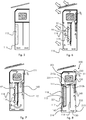
figures 6 et 7 , des vues schématiques en coupe d'un troisième mode de réalisation, respectivement lorsque le boîtier emmagasine de la chaleur extérieure et lorsque le boîtier redistribue de la chaleur au produit en raison des fluctuations de température extérieures durant l'exploitation d'un boîtier selon l'invention muni d'un système de chauffage «Trombe» du matériau à changement de phase ; - la
figure 8 , une vue schématique en coupe d'une première variante de boîtier desfigures 6 et 7 , muni d'un volume de matériau à changement de phase fixé au système de chauffage « Trombe » ; - Les
figure 9 à 12 , des vues schématiques en coupe du boîtier de lafigure 8 , dans différentes situations d'utilisation ; - La
figure 13 , une vue schématique en coupe d'un sixième mode de réalisation d'un boitier selon l'invention, dans lequel la chambre de régulation est agencée latéralement par rapport à la chambre de stockage ; et - La
figure 14 , une vue schématique en coupe d'un septième mode de réalisation d'un boitier selon l'invention, dans lequel la chambre de régulation est agencée au-dessus de la chambre de stockage.
- the
Figures 1 and 2 , schematic sectional views of two variants of a first embodiment of a housing according to the invention in summer period, day and night respectively; - the
figures 3 and 4 , schematic sectional views of a variant of the embodiment of the housings of theFigures 1 and 2 , in winter period, day and night respectively, and provided with a remote monitoring system and a means of controlled heating of the phase change material; - the
figure 5 , a schematic sectional view of a second embodiment of a housing according to the invention, in which the volume of phase change material is fixed against the external wall of the regulation chamber; - the
Figures 6 and 7 , schematic sectional views of a third embodiment, respectively when the casing stores external heat and when the casing redistributes heat to the product due to the external temperature fluctuations during the operation of a casing according to the invention provided with a "whirlwind" heating system of the phase change material; - the
figure 8 , a schematic sectional view of a first variant of the housing of theFigures 6 and 7 , provided with a volume of phase change material attached to the "Trombe" heating system; - The
figure 9 to 12 , schematic sectional views of the housing of thefigure 8 , in different situations of use; - The
figure 13 , a schematic sectional view of a sixth embodiment of a housing according to the invention, in which the regulation is arranged laterally with respect to the storage chamber; and - The
figure 14 , a schematic sectional view of a seventh embodiment of a housing according to the invention, in which the regulation chamber is arranged above the storage chamber.
L'invention est décrite ci-après avec un moyen de chauffage utilisant l'énergie solaire. Cependant, il est également possible d'utiliser un moyen de chauffage utilisant la géothermie de surface dans les lieux adaptés.The invention is described below with a heating means using solar energy. However, it is also possible to use a heating means using surface geothermal energy in suitable places.
Le mode de réalisation illustré est particulièrement adapté à un boîtier de type « boîtier pour défibrillateur externe » sur pied.The illustrated embodiment is particularly suitable for a type of box "box for external defibrillator" on foot.
Le boîtier 100 illustré en
La chambre de stockage 101 est munie d'un support (non illustré par souci de clarté) pour le produit à stocker P, agencé de telle sorte que de l'air puisse circuler autour de l'objet P.The
Le boîtier 100 selon l'invention illustré dans cet exemple comprend également une chambre de régulation inférieure 110, séparée de la chambre de stockage 101 par une cloison 111, ici horizontale, munie de deux orifices de passage d'air 1 12a- et 1 12b.The
Une paroi de canalisation 114 est fixée entre les deux orifices de passage d'air par une seule extrémité, délimitant un circuit de circulation d'air avec une colonne de montée d'air et une colonne de descente d'air et un passage entre ces deux colonnes, en bas de la chambre de régulation 110 dans la configuration illustrée. À cette fin, la paroi de canalisation 114 est de longueur inférieure à la longueur de la chambre de régulation 110 pour laisser passer l'air entre la colonne de montée d'air et la colonne de descente d'air. Dans une variante non illustrée, la paroi de canalisation 114 peut séparer totalement la chambre de régulation en deux et être fixée par deux extrémités à ladite chambre. Dans ce cas, elle doit comporter un orifice suffisamment grand pour permettre une circulation d'air entre les deux colonnes de circulation d'air ainsi ménagées.A
Selon l'invention, la chambre de régulation 110 comprend également un volume déterminé d'un matériau à changement de phase 115.According to the invention, the
Avantageusement, le matériau à changement de phase choisi est de type paraffines car elles ne présentent pas de perte ou de modification de leurs caractéristiques physiques liées à leur vieillissement. Le boîtier selon l'invention peut donc rester opérationnel sur une durée pluriannuelle sans perte d'efficience qui serait due à un vieillissement des propriétés réactives du matériau à changement de phase.Advantageously, the phase change material chosen is of the paraffin type because they do not exhibit any loss or modification of their physical characteristics linked to their aging. The housing according to the invention can therefore remain operational over a multiannual period without loss of efficiency which would be due to aging of the reactive properties of the phase change material.
L'autre avantage est que la température de changement de phase des paraffines est compatible avec les températures été/hiver de très nombreux pays.The other advantage is that the phase change temperature of the paraffins is compatible with the summer / winter temperatures of very many countries.
La conductivité thermique du matériau à changement de phase étant souvent faible, elle peut être avantageusement augmentée par l'ajout d'un matériau conducteur de chaleur divisé tel que le graphite. On entend par matériau conducteur de chaleur divisé un matériau conducteur de chaleur particulaire, par exemple une poudre ou un ensemble de paillettes.Since the thermal conductivity of the phase change material is often low, it can be advantageously increased by adding a divided heat conducting material such as graphite. By divided heat conducting material is meant a particulate heat conducting material, for example a powder or a set of flakes.
Le composite ainsi mis en œuvre permet d'obtenir les niveaux de puissance de charge et décharge thermique souhaités. Ce paramètre de conductivité doit être optimisé en fonction de la quantité de matériau à changement de phase utilisé, de la surface d'échange entre le matériau à changement de phase et l'air ventilé, de la différence de température entre l'air et le matériau à changement de phase et de la vitesse d'écoulement de l'air ventilé.The composite thus used makes it possible to obtain the desired charge power and thermal discharge levels. This conductivity parameter must be optimized as a function of the quantity of phase change material used, of the exchange surface between the phase change material and the ventilated air, of the temperature difference between the air and the phase change material and the flow velocity of the ventilated air.
La combinaison du matériau à changement de phase avec un matériau conducteur de chaleur divisé peut être faite par mélange du matériau à changement de phase et du matériau conducteur de chaleur divisé. Alternativement, le matériau conducteur de chaleur divisé peut être contenu dans une enveloppe conductrice de chaleur en contact thermique avec le matériau à changement de phase et absorbant l'énergie solaire.The combination of the phase change material with a divided heat conductive material can be made by mixing the phase change material and the divided heat conductive material. Alternatively, the divided heat conducting material can be contained in a heat conducting envelope in thermal contact with the phase change material and absorbing solar energy.
Selon l'invention, le matériau à changement de phase et/ou le mélange de plusieurs matériaux à changement de phase et/ou le mélange d'un ou plusieurs matériau(x) à changement de phase avec un matériau conducteur de chaleur divisé de type graphite, sont choisi pour que la température de changement de phase soit entre la température minimale et la température maximale de la gamme de température dans laquelle doit être stocké l'objet P.According to the invention, the phase change material and / or the mixture of several phase change materials and / or the mixture of one or more phase change material (s) with a divided heat conducting material of the type graphite, are chosen so that the phase change temperature is between the minimum temperature and the maximum temperature of the temperature range in which the object P must be stored.
Selon l'invention, on choisit le matériau à changement de phase (ou un mélange) qui présente une température de changement de phase (fusion/liquéfaction) sensiblement égale à la moyenne de la gamme de température de stockage : si cette dernière est comprise entre 15°C et 45°C, on peut choisir un matériau à changement de phase (ou un mélange) dont la température de changement de phase est sensiblement égale à 30°C.According to the invention, the phase change material (or a mixture) is chosen which has a phase change temperature (fusion / liquefaction) substantially equal to the average of the storage temperature range: if the latter is between 15 ° C and 45 ° C, it is possible to choose a phase change material (or a mixture) whose phase change temperature is substantially equal to 30 ° C.
Ainsi, le matériau à changement de phase n'est pas choisi pour que sa température de changement de phase soit égale à la température maximale ou la température minimale de la gamme de température de stockage de consigne de l'objet.Thus, the phase change material is not chosen so that its phase change temperature is equal to the maximum temperature or the minimum temperature of the set point storage temperature range of the object.
Selon l'invention, le boîtier 100 comprend également un moyen de chauffage du matériau à changement de phase.According to the invention, the
Dans le mode de réalisation illustré en
Cependant, ces transferts thermiques ne sont pas les plus efficaces. Un mode de réalisation avantageux illustré en
Dans le mode de réalisation illustré, le volume de matériau à changement de phase est avantageusement supporté par une paroi 116 de la chambre inférieure de régulation 110, de préférence par des fixations 115a conductrices de chaleur. Un autre mode de réalisation est illustré en
En été, la température haute extrême est atteinte le jour et il convient globalement de maintenir l'objet au frais.In summer, the extreme high temperature is reached during the day and the object should generally be kept cool.
Le jour (
Ceci génère une circulation naturelle d'air : l'air chaud remonte (flèche F1) et l'air frais descend (flèche F2).This generates a natural circulation of air: the hot air rises (arrow F1) and the fresh air descends (arrow F2).
L'air chaud transmet sa chaleur au matériau à changement de phase 115 (flèche F3) qui se liquéfie au fur et à mesure. Ce changement de phase se fait à température constante, de sorte que l'objet P, structurellement protégé d'un effet potentiel de surchauffe par la couche isolante 102, est également maintenu à une température proche de la température de changement de phase grâce à la circulation d'air tempéré qui a cédé sa chaleur au matériau à changement de phase 115.The hot air transmits its heat to the phase change material 115 (arrow F3) which liquefies progressively. This phase change takes place at constant temperature, so that the object P, structurally protected from a potential effect of overheating by the insulating
Ainsi, la chaleur à évacuer au niveau de l'objet P est stockée par le matériau à changement de phase 115 par fusion de ce dernier. En d'autres termes, la température de changement d'état du matériau à changement de phase empêche l'objet P de monter en température.Thus, the heat to be removed at the level of the object P is stored by the
Pendant la nuit (
L'air environnant extérieur permet ainsi de solidifier le matériau à changement de phase 115 qui est alors à nouveau disponible pour protéger le contenu le jour suivant en rafraîchissant l'air intérieur du boîtier.The surrounding external air thus makes it possible to solidify the
Le volume de matériau à changement de phase est donc choisi selon les températures du lieu géographique pour que cette solidification totale n'arrive qu'en toute fin de nuit, lorsque la température commence à remonter, et que la liquéfaction totale n'arrive qu'en fin d'après-midi, lorsque la température commence à baisser.The volume of phase change material is therefore chosen according to the temperatures of the geographic location so that this total solidification does not occur until the end of the night, when the temperature begins to rise, and that the total liquefaction only occurs. late afternoon, when the temperature starts to drop.
Ainsi, le matériau à changement de phase 115 est utilisé pour tempérer le produit P par ventilation d'air entre les deux chambres 101 et 110.Thus, the
La chambre de régulation 110 est ainsi équipée d'un circuit de circulation d'air assurant les transferts thermiques entre l'objet P, placé dans la chambre de stockage supérieure, et le matériau à changement de phase 115. La nuit, lorsque l'objet P est à réchauffer par le matériau à changement de phase 115, l'air est ventilé par convection naturelle. Le jour, lorsque le contenu est à refroidir par le matériau à changement de phase 115, l'air est avantageusement mis en mouvement par des ventilateurs 130 pour forcer la ventilation d'air à l'intérieur du boîtier, et commandés par un microcontrôleur.The
Ces ventilateurs n'ont pas besoin d'être très puissants, de sorte qu'ils ne consomment que très peu d'énergie. Pour les alimenter, le boitier selon l'invention comprend avantageusement un panneau 120 recouvert de cellules photovoltaïques 141 reliées électriquement aux ventilateurs 130 (connexion non illustrée par souci de clarté des figures). Alternativement, ils peuvent être alimentés par des piles présentant plusieurs années de durée de vie.These fans do not need to be very powerful, so they consume very little energy. To power them, the box according to the invention advantageously comprises a
Plus précisément, les cellules photovoltaïques 141 sont reliées à une batterie 140 qui alimente électriquement un microcontrôleur 150 commandant le fonctionnement d'équipements électriques compris dans le boîtier, notamment le ou les ventilateurs 130.More specifically, the
Les
Dans le mode de réalisation illustré, le chauffage par conduction par la paroi 116 est complété par une résistance électrique 117 en contact thermique avec le matériau à changement de phase 115, ce qui améliore le rendement du chauffage du matériau à changement de phase. Cette résistance électrique 117 est reliée au microcontrôleur 150 et alimentée par les cellules photovoltaïques 141. Le microcontrôleur 150 commande avantageusement le fonctionnement de la résistance électrique en fonction de données de température qu'il récupère de sondes de température 160 disposés à différents endroits du boîtier.In the illustrated embodiment, the heating by conduction through the
Au cours de la journée (
Si la température extérieure est suffisante pour liquéfier le matériau à changement de phase 115, ce dernier absorbe de la chaleur en changeant de phase, énergie qu'il restituera la nuit lorsque la température baissera.If the outside temperature is sufficient to liquefy the
Cependant, en général, la température extérieure du jour est insuffisante, en hiver, pour liquéfier le matériau à changement de phase 115.However, in general, the outside day temperature is insufficient in winter to liquefy the
Selon l'invention, la résistance électrique alimentée par les cellules photovoltaïques permet de chauffer par effet de Joule le matériau à changement de phase et de liquéfier, pendant la journée. Le matériau à changement de phase retransmettra pendant la nuit de la chaleur à l'objet en retournant à l'état solide.According to the invention, the electrical resistance supplied by the photovoltaic cells makes it possible to heat by Joule effect the material with change of phase and to liquefy, during the day. The phase change material will return heat to the object overnight, returning to the solid state.
Ainsi, le jour (
Ainsi, la nuit (
Les
Dans ce mode de réalisation, la chambre de régulation 110 est munie d'un vitrage 118 sur la face de la chambre 110 qui est exposée au soleil en position d'utilisation.In this embodiment, the
En regard du vitrage 118, le boîtier selon l'invention comprend une plaque de capture de chaleur 119 recouvrant le volume de matériau à changement de phase 115. Alternativement ou en combinaison, le matériau à changement de phase peut être recouvert d'une enveloppe conductrice de chaleur peinte en noir 221 (voir
Le vitrage 118 et la plaque de capture de chaleur 119 constituent un système de chauffage de type «Trombe» du matériau à changement de phase 115.The
Le système de chauffage de type « Trombe » disposé sur le boîtier 100 permet de capter le rayonnement solaire et de le convertir en chaleur : la surface noire de la plaque 119 ou de l'enveloppe 221 absorbe le rayonnement solaire, le converti en chaleur directement et le transfert au matériau à changement de phase 115 (flèches F5). En outre, la surface noire rayonne dans l'infrarouge et ce rayonnement bloqué par effet de serre par le vitrage (flèche F6) est utilisé en partie pour réchauffer directement l'objet P et pour le reste à stocker de la chaleur dans le matériau à changement de phase 115 en le liquéfiant. Ce dernier est alors fonctionnel pour la nuit (
Dans la variante des
Les meilleurs rendements sont obtenus lorsque le volume de matériau à changement de phase 115 est supporté par une paroi 116 de la chambre inférieure de régulation 110, en regard et à distance du vitrage 118, de manière à ménager un double circuit de circulation d'air de part et d'autre du volume de matériau à changement de phase. Cette variante est illustrée aux
Le mode de réalisation illustré en
Ainsi, la chambre de régulation 210 du boîtier 200 comprend une paroi 216 munie d'un vitrage 118 sur une face destinée à être exposée au soleil. Le volume déterminé de matériau à changement de phase 115 est fixé à distance de la paroi 216 qui le porte, de manière à ménager un double circuit de circulation d'air de part et d'autre du volume de matériau à changement de phase. Cet agencement préféré maximise le rendement d'échange thermique et le fonctionnement du boîtier.Thus, the
Le volume déterminé de matériau à changement de phase 115 est également recouvert d'une plaque de capture de chaleur 221, ici sous forme d'une enveloppe complète, mais seule la face agencée en regard du vitrage pourrait être seules recouverte.The determined volume of
Ce mode de réalisation illustre également la possibilité avantageuse d'équiper chacun des orifices de passage d'air séparant la chambre de régulation 210 de la chambre de stockage 201 avec une trappe commandable, respectivement 213a et 213b entre une position ouverte autorisant un passage d'air et une position fermée bloquant le passage de l'air. Sur les figures, la position fermée est illustrée par un rectangle barré et la position ouverte par un rectangle plein.This embodiment also illustrates the advantageous possibility of equipping each of the air passage orifices separating the
Concomitamment, le boîtier 200 est équipé de ventilateurs 130 commandables par le microcontrôleur 150 afin de générer des flux d'air dans une direction souhaitée. Les ventilateurs peuvent être inversés pour inverser la direction du flux d'air.Concomitantly, the
Dans un mode de réalisation non illustré, les trappes commandables 213a et 213b sont elles mêmes équipées de ventilateurs inversables, ce qui rend les échanges d'air entre la chambre de stockage et la chambre de régulation plus efficaces et plus précis.In an embodiment not illustrated, the
Un autre perfectionnement particulièrement utile est la présence d'orifices d'entrée/sortie d'air commandables entre l'intérieur et l'extérieur du boîtier 200 : deux orifices d'entrée/sortie d'air 230 et 231 dans la chambre de stockage, et un orifice d'entrée/sortie d'air 232 dans la chambre de régulation.Another particularly useful improvement is the presence of controllable air inlet / outlet ports between the inside and the outside of the housing 200: two air inlet /
De préférences, les orifices d'entrée/sortie d'air 230 et 231 sont agencées de part et d'autre de l'objet stocké et de son support de manière à favoriser une circulation d'air autour de l'objet.Preferably, the air inlet /
Sur les figures, la position fermée est illustrée par un rectangle barré et la position ouverte par un rectangle plein.In the figures, the closed position is illustrated by a crossed-out rectangle and the open position by a solid rectangle.
Les trappes commandables et les orifices d'entrée/sortie d'air commandables sont soit commandées électriquement par le microcontrôleur, soit commandée mécaniquement en fonction des conditions de température.The controllable hatches and the controllable air inlet / outlet ports are either electrically controlled by the microcontroller, or mechanically controlled depending on the temperature conditions.
Comme précédemment décrit, le matériau à changement de phase est avantageusement combiné avec un matériau conducteur de chaleur divisé, tel que du graphite.As previously described, the phase change material is advantageously combined with a divided heat conducting material, such as graphite.
Le matériau à changement de phase 115 est également avantageusement en contact thermique avec une résistance électrique 117 alimentée par le microcontrôleur 150 en fonction des conditions de température et d'humidité captées par différents équipements électroniques de contrôle 160 incorporés au boîtier, par exemple : une sonde de température, un capteur d'hygrométrie, un capteur d'état de l'objet stocké (Par exemple un capteur optique servant à contrôler l'état de marche d'un défibrillateur stocké ou un capteur de gaz), un contact sec, ou un assortiment de ceux-ci.The
L'ensemble est alimenté par un panneau de cellules photovoltaïques 141 relié à une batterie 140 elle-même reliée au microcontrôleur 150.The assembly is supplied by a panel of
La
Il peut s'agir, par exemple, d'une journée d'été pendant laquelle le boîtier reçoit un rayonnement S. dans ce cas, la température intérieure du boitier augmente et devient supérieure à la température de l'air extérieur. L'objectif est donc de limiter l'échauffement de l'objet.It may be, for example, a summer day during which the box receives an S radiation. In this case, the inside temperature of the box increases and becomes higher than the temperature of the outside air. The objective is therefore to limit the heating of the object.
Lorsque la température intérieure du boîtier est supérieure à une température seuil donnée (par exemple la température extérieure), les trappes 213a et 213b se ferment, et les orifices d'entrée/sortie d'air 230 et 231 s'ouvrent pour permettre une circulation d'air extérieur autour de l'objet (flèche F8) dans la chambre de stockage 201 par convection naturelle.When the inside temperature of the housing is higher than a given threshold temperature (for example the outside temperature), the
En effet, l'invention prévoit que l'orifice d'entrée/sortie 231 est agencé à une hauteur inférieure que l'orifice d'entrée/sortie 230. L'air chaud (réchauffé par le rayonnement du soleil) sort donc par ce dernier (flèche F9), et l'air plus frais de l'extérieur entre par l'orifice 231 (flèche F10). En outre, les orifices d'entrée/sortie 230-231 sont agencé de manière opposée par rapport à l'objet, forçant ainsi le passage de l'air autour de l'objet.Indeed, the invention provides that the inlet /
Dans cette situation, la chambre de régulation est isolée de la chambre de stockage car les trappes 213a et 213b sont fermées.In this situation, the regulation chamber is isolated from the storage chamber because the
Le rayonnement lumineux passe au travers du vitrage et chauffe le matériau à changement de phase, comme expliqué précédemment. Ce dernier emmagasine donc de la chaleur qu'il pourra retransmettre plus tard.The light radiation passes through the glazing and heats the phase change material, as explained above. The latter therefore stores heat which it can retransmit later.
Cette situation a également lieu lors d'une journée d'hiver, lorsque le rayonnement chauffe fortement la chambre de stockage mais que l'air extérieur est frais. Dans ce cas, le rayonnement charge le matériau à changement de phase en chaleur en vue de la nuit (pour réchauffer l'objet). Le jour, l'objet est refroidi par la circulation d'air frais extérieur.This situation also occurs during a winter day, when the radiation strongly heats the storage chamber but the outside air is cool. In this case, the radiation charges the phase change material with heat for the night (to heat the object). During the day, the object is cooled by the circulation of fresh outside air.
Cette situation a également lieu lorsque la température extérieure est supérieure à la température du changement de phase du matériau à changement de phase. Dans ce cas, l'échange thermique direct par circulation d'air est plus efficace qui l'échange thermique via le matériau à changement de phase de la chambre de régulation.This situation also occurs when the outside temperature is higher than the phase change temperature of the phase change material. In this case, the direct heat exchange by air circulation is more efficient which the heat exchange via the phase change material of the regulation chamber.
La
Dans ce cas, l'orifice d'entrée/sortie supérieur 230 est ouverte, alors que l'orifice d'entrée/sortie inférieure 231 est fermée. L'orifice d'entrée/sortie 232 de la chambre de régulation, agencé dans la colonne d'air opposée à la colonne d'air dans laquelle est située le volume de matériau à changement de phase, est ouvert.In this case, the upper inlet /
La trappe 213a, débouchant dans la colonne d'air dans laquelle est située le volume de matériau à changement de phase, est ouverte, alors que la trappe 213b débouchant dans la colonne d'air opposée à la colonne d'air dans laquelle est située le volume de matériau à changement de phase, est fermée.The
La circulation d'air est forcée par l'actionnement des ventilateurs 130, de sorte que l'air extérieur entre dans le boîtier par l'orifice 230 (flèche F11), circule autour de l'objet en le rafraîchissant (flèche F12), et pénètre dans la chambre de régulation par la trappe 213a (flèche F13). les ventilateurs sont alimentés par la batterie chargée au cours de la journée par les panneaux solairesThe air circulation is forced by the actuation of the
Au contact du matériau à changement de phase 115, l'air extérieur rafraîchit le matériau à changement de phase (flèche F14) qui change de phase en se solidifiant. Ce faisant, il réchauffe l'air qui est évacué par l'orifice 232 (flèche F15) car il ne peut remonter vers l'objet puisque la trappe 213b est fermée.On contact with the
Les
La
Pour limiter le refroidissement de l'objet, les orifices d'entrée/sortie 230, 231 et 232 sont fermés.To limit the cooling of the object, the inlet /
En période froide, la température extérieure la journée reste inférieure à la température de changement de phase du matériau à changement de phase.During the cold period, the daytime outside temperature remains below the phase change temperature of the phase change material.
Le rayonnement lumineux transmis par le vitrage réchauffe le matériau à changement de phase qui emmagasine de la chaleur en changeant de phase. L'air se réchauffe au contact du matériau à changement de phase : entre le matériau à changement de phase et le vitrage (flèche F16), et entre le matériau à changement de phase et la paroi de canalisation 114 (flèche F17).The light radiation transmitted by the glazing heats up the phase change material which stores heat by changing phase. The air heats up on contact with the phase change material: between the phase change material and the glazing (arrow F16), and between the phase change material and the pipe wall 114 (arrow F17).
L'air chaud remonte naturellement et entre dans la chambre de stockage par la trappe 213a qui est ouverte (flèche F18).The hot air rises naturally and enters the storage chamber through the
L'air chaud circule autour de l'objet et le garde en température (flèche F19).Hot air circulates around the object and keeps it at temperature (arrow F19).
L'air se refroidit au contact de l'objet et redescend dans la chambre de régulation par la trappe 213b ouverte (flèche F20), débouchant dans la colonne d'air opposée à la colonne d'air dans laquelle est située le volume de matériau à changement de phase.The air cools in contact with the object and descends into the regulation chamber through the
Si le rayonnement lumineux est un peu faible, l'apport de chaleur au matériau à changement de phase peut être complété par l'alimentation de la résistance 117. Alternativement ou en combinaison, on peut utiliser un matériau à changement de phase combiné à un matériau conducteur de chaleur divisé afin d'améliorer le rendement de transfert de chaleur et obtenir la puissance de stockage/déstockage voulue.If the light radiation is a little weak, the addition of heat to the phase change material can be supplemented by supplying the
En cas d'excès de chaleur dans la chambre de stockage, les orifices d'entrée/sortie230-231 peuvent être ouverts temporairement.In the event of excess heat in the storage chamber, the 230-231 inlet / outlet ports may be temporarily opened.
La
Dans ce cas, la convection naturelle amorcée pendant la journée se poursuit pendant la nuit, alimentée par le réchauffement de l'air lors du changement de phase du matériau à changement de phase.In this case, the natural convection initiated during the day continues during the night, fed by the heating of the air during the phase change of the phase change material.
Dans les modes de réalisation précédents, l'agencement supérieur de la chambre de stockage par rapport à la chambre de régulation en position inférieure permet une convection naturelle de l'air dans certaines conditions de température. Cet agencement est particulièrement avantageux lorsqu'il est possible d'installer un tel boîtier.In the previous embodiments, the upper arrangement of the storage chamber with respect to the regulation chamber in the lower position allows natural convection of the air under certain temperature conditions. This arrangement is particularly advantageous when it is possible to install such a housing.
Cependant, dans certains cas, il peut être souhaitable de modifier un coffre préexistant stockant un objet devant être thermo-régulé afin, par exemple, de diminuer la consommation d'énergie utilisée pour cette régulation thermique.However, in some cases, it may be desirable to modify a pre-existing safe storing an object to be thermo-regulated in order, for example, to reduce the energy consumption used for this thermal regulation.
Il n'est alors pas possible à des coûts raisonnables d'insérer une chambre de régulation selon l'invention sous le coffre préexistant pour lui donner la fonction de chambre de stockage selon l'invention.It is therefore not possible at reasonable costs to insert a regulation chamber according to the invention under the pre-existing trunk to give it the function of storage chamber according to the invention.
La
Dans cet agencement, une chambre de régulation 310 selon l'invention est agencée latéralement par rapport à la chambre de stockage 301.In this arrangement, a
La
Dans cet agencement, une chambre de régulation 410 selon l'invention est agencée au-dessus par rapport à la chambre de stockage 401.In this arrangement, a
Lors de l'adaptation, il faut ouvrir deux orifices de passage d'air entre la chambre de régulation et la chambre de stockage, puis installer l'ensemble équipement électriques et électroniques. Avantageusement, on percera également la chambre de stockage avec des orifices d'entrée/sortie d'air.When adapting, you must open two air passage openings between the regulation chamber and the storage chamber, then install the electrical and electronic equipment assembly. Advantageously, the storage chamber will also be pierced with air inlet / outlet openings.
Dans tous les modes de réalisation précédents, le fonctionnement et/ou le contrôle à distance peut/peuvent être assuré(s) grâce au microcontrôleur 150 et à des capteurs électroniques 160, tels que des sondes de températures ainsi qu'à des capteurs d'hygrométrie et différents contacts sec, disposées au niveau de chaque élément constitutif du boîtier selon l'invention (matériau à changement de phase 115, colonnes d'air, chambre de stockage 101, surface extérieur).In all the previous embodiments, the operation and / or the remote control can / can be ensured thanks to the
Le boîtier selon l'invention comprend également avantageusement un module de télécommunication permettant notamment de superviser à distance les températures relevées à chaque niveau des composants par les capteurs 160 de température.The box according to the invention also advantageously comprises a telecommunication module making it possible in particular to remotely monitor the temperatures recorded at each level of the components by the
À cette fin, le microcontrôleur 150 est avantageusement équipé d'un système de communication comprenant un émetteur/récepteur 151 de liaison sans fil, de préférence de type LRWA (Long Range Wild Area) à basse consommation énergétique.To this end, the
Ce type d'émetteur récepteur 151 est capable d'émettre et de recevoir des données sur un réseau étendu sans fil à faible consommation énergétique, dit « LPWAN » et/ou sur un réseau local sans fil à faible consommation énergétique, dit « LPLAN ».This type of
Par exemple, l'émetteur/récepteur 151 est capable d'émettre et de recevoir selon les protocoles de communication éprouvés et fréquemment utilisés dans les réseaux dits de type « IoT » . Ces modes de communication sont bas débit, de longue portée et très peu énergivores.For example, the transmitter /
Avantageusement, une carte électronique spécifiquement adaptée à la surveillance du contenu et communicant au travers des réseaux LRWA peut garantir un suivi permanent de l'environnement et de son état.Advantageously, an electronic card specifically adapted for monitoring content and communicating through LRWA networks can guarantee permanent monitoring of the environment and its state.
L'utilisation de ces réseaux à très basse consommation électrique permet un fonctionnement autonome soit au travers de capacités elles-mêmes alimentées par les cellules photovoltaïques, soit au travers de piles ou batteries.The use of these networks with very low power consumption allows autonomous operation either through capacities themselves supplied by photovoltaic cells, or through cells or batteries.
Dans le cas de l'option de surveillance et de contrôle à distance, un serveur de type « cloud » permet de superviser un ensemble de boîtiers selon l'invention, géolocalisés sur une carte, et d'accéder individuellement à chacun des boîtiers et du relevé des données issues de l'ensemble des équipements électroniques de contrôle 160 tels que les sondes de température, les capteurs hygrométriques et les contacts sec stockés sur une mémoire (non illustrée) reliés au microcontrôleur 150.In the case of the remote monitoring and control option, a “cloud” type server makes it possible to supervise a set of boxes according to the invention, geolocated on a map, and to individually access each of the boxes and the reading of data from all the
La combinaison d'un isolant à haute résistance thermique et faible conductivité associé à un volume de matériau à changement de phase spécifiquement adapté au niveau des températures recherchées, l'ensemble couplé à des échanges thermiques avec l'environnement extérieur immédiat, à un moyen de chauffage du matériau à changement de phase (système trombe ou résistance électrique alimentée par des cellules photovoltaïques) et un circuit de ventilation, permet d'assurer au boîtier des températures régulées avec de faibles écarts de variations sur des plages de 24 heures.The combination of an insulator with high thermal resistance and low conductivity associated with a volume of phase change material specifically adapted to the level of the desired temperatures, the assembly coupled with heat exchanges with the immediate external environment, with a means of heating of the phase change material (downpour or electric resistance supplied by photovoltaic cells) and a ventilation circuit, allows to assure the case of the regulated temperatures with small variations variations on ranges of 24 hours.
La solution selon l'invention permet de s'affranchir de toutes sources d'énergies extérieures au boîtier autres que son environnement extérieur immédiat et sources d'énergies renouvelables telle que le solaire, et d'éviter l'utilisation d'énergies fossiles ou de matériaux chimiques à recharger.The solution according to the invention makes it possible to dispense with all sources of energy external to the housing other than its immediate external environment and sources of renewable energy such as solar, and to avoid the use of fossil energies or chemical materials to be recharged.
L'invention permet au dispositif d'être protégé des contraintes en températures (variations) rencontrées entre le jour et la nuit mais aussi été comme hiver (lorsque le contenu est limité en température haute et basse).The invention allows the device to be protected from temperature constraints (variations) encountered between day and night but also summer and winter (when the content is limited at high and low temperatures).
Un tel dispositif permet de s'affranchir des besoins en recharge d'énergie et reste opérationnel sur une durée pluriannuelle sans perte d'efficience.Such a device eliminates the need for energy recharging and remains operational over a multi-year period without loss of efficiency.
Il est alors possible de stocker un objet, tel qu'un défibrillateur, de manière sûr, y compris dans des endroits non raccordés au réseau électrique.It is then possible to store an object, such as a defibrillator, safely, including in places not connected to the electrical network.
Les dimensions du boîtier et de ses composants, le choix du matériau à changement de phase et l'ajout éventuel d'un matériau conducteur de chaleur divisé et/ou d'une résistance électrique, peuvent varier en fonction du produit à stocker (la nature de l'énergie renouvelable sollicitée peut varier aussi: on peut utiliser le solaire et/ou la géothermie de surface).The dimensions of the housing and of its components, the choice of the phase change material and the possible addition of a divided heat conducting material and / or an electrical resistance, may vary depending on the product to be stored (the nature renewable energy requested can also vary: we can use solar and / or surface geothermal energy).
Claims (19)
Applications Claiming Priority (1)
| Application Number | Priority Date | Filing Date | Title |
|---|---|---|---|
| FR1801050A FR3087003B1 (en) | 2018-10-04 | 2018-10-04 | AUTONOMOUS THEMO-REGULE BOX |
Publications (2)
| Publication Number | Publication Date |
|---|---|
| EP3633304A1 true EP3633304A1 (en) | 2020-04-08 |
| EP3633304B1 EP3633304B1 (en) | 2020-12-09 |
Family
ID=65243635
Family Applications (1)
| Application Number | Title | Priority Date | Filing Date |
|---|---|---|---|
| EP19199574.5A Active EP3633304B1 (en) | 2018-10-04 | 2019-09-25 | Standalone regulated thermo-box |
Country Status (4)
| Country | Link |
|---|---|
| EP (1) | EP3633304B1 (en) |
| ES (1) | ES2859498T3 (en) |
| FR (1) | FR3087003B1 (en) |
| WO (1) | WO2020069947A1 (en) |
Cited By (1)
| Publication number | Priority date | Publication date | Assignee | Title |
|---|---|---|---|---|
| WO2021219546A1 (en) * | 2020-04-27 | 2021-11-04 | Trisult Holding B.V. | Portable aed case |
Citations (3)
| Publication number | Priority date | Publication date | Assignee | Title |
|---|---|---|---|---|
| US4928501A (en) * | 1988-03-17 | 1990-05-29 | Sanden Corporation | Cold preserving container |
| US20160243000A1 (en) * | 2013-10-17 | 2016-08-25 | David Gray | A portable temperature controlled container |
| US20180133495A1 (en) * | 2016-11-17 | 2018-05-17 | Alan Himelfarb | System and methods for storing an automated external defibrillator |
-
2018
- 2018-10-04 FR FR1801050A patent/FR3087003B1/en active Active
-
2019
- 2019-09-25 EP EP19199574.5A patent/EP3633304B1/en active Active
- 2019-09-25 ES ES19199574T patent/ES2859498T3/en active Active
- 2019-09-25 WO PCT/EP2019/075957 patent/WO2020069947A1/en active Application Filing
Patent Citations (3)
| Publication number | Priority date | Publication date | Assignee | Title |
|---|---|---|---|---|
| US4928501A (en) * | 1988-03-17 | 1990-05-29 | Sanden Corporation | Cold preserving container |
| US20160243000A1 (en) * | 2013-10-17 | 2016-08-25 | David Gray | A portable temperature controlled container |
| US20180133495A1 (en) * | 2016-11-17 | 2018-05-17 | Alan Himelfarb | System and methods for storing an automated external defibrillator |
Cited By (1)
| Publication number | Priority date | Publication date | Assignee | Title |
|---|---|---|---|---|
| WO2021219546A1 (en) * | 2020-04-27 | 2021-11-04 | Trisult Holding B.V. | Portable aed case |
Also Published As
| Publication number | Publication date |
|---|---|
| FR3087003A1 (en) | 2020-04-10 |
| FR3087003B1 (en) | 2020-10-02 |
| EP3633304B1 (en) | 2020-12-09 |
| WO2020069947A1 (en) | 2020-04-09 |
| ES2859498T3 (en) | 2021-10-04 |
Similar Documents
| Publication | Publication Date | Title |
|---|---|---|
| US20150083180A1 (en) | Systems, methods and/or apparatus for thermoelectric energy generation | |
| CA2955881A1 (en) | Device and method for storing thermal energy | |
| FR2471562A1 (en) | MODULAR DEVICE FOR PERFORMING HEATING OR COOLING FROM SOLAR ENERGY BY AN INTERMITTENT CYLINDER OF ADSORPTION HEAT PUMP, AND APPARATUS COMPRISING SUCH DEVICES | |
| KR20140101805A (en) | Systems, methods and/or apparatus for thermoelectric energy generation | |
| WO2010004131A2 (en) | Method and device providing the temperature regulation of a rechargeable electrical energy storage battery | |
| EP3633304B1 (en) | Standalone regulated thermo-box | |
| EP3274639B1 (en) | Solar device for autonomeous production of cold by adsorption | |
| FR2511133A1 (en) | SOLAR ENERGY COLLECTOR WITH INTEGRATED HEAT ACCUMULATOR AND RADIATOR | |
| EP3925014A2 (en) | Thermoelectric device employing the seebeck effect | |
| EP2366845B1 (en) | Active thermal insulation method and device for implementing said method | |
| FR2864174A1 (en) | Electricity generating device for e.g. domestic purpose, has container in which passages orient compressed air towards compartments that confine air onto wheel, connected to alternator, rotated under effect of buoyancy due to air | |
| BE1026401B1 (en) | DEVICE FOR REGULATING THE TEMPERATURE IN A SPEAKER | |
| EP3571963B1 (en) | Thermo adjustable device for receiving and storing a parcel and system including same | |
| WO2011080490A2 (en) | Stored-energy solar central heating device | |
| EP0878668B1 (en) | Thermal convection device with natural draft for reversible air-conditioning unit | |
| CA1244732A (en) | Two way thermovane, installation for the production and starage of heat or cold incorporating said thermovane, and various uses for said installation | |
| FR3048767A1 (en) | THERMAL BARRIER AND INTERNAL HEAT STORAGE ELEMENT | |
| WO2020115428A1 (en) | Modular battery comprising a thermal conditioning system | |
| WO2015186100A1 (en) | Installation for converting heat into mechanical energy with an improved system for cooling the working fluid | |
| WO2024047252A1 (en) | Device for cooling a data center computer server by using a phase change material | |
| FR3047022A1 (en) | BUILDING ENVELOPE ELEMENT COMPRISING PHASE CHANGE MATERIAL, AND CORRESPONDING BUILDING | |
| WO2017140326A1 (en) | Autonomous unit for generating electrical power higher than 150 kwp of a field of photovoltaic panels, contained in a shelter, intended for installations in hot countries, without requiring the availability of power sources via an electricity grid and without negatively affecting the yield of solar energy production | |
| FR3005145A1 (en) | WALL-HEATING AND / OR REFRESHING DEVICE HAVING A SOLAR THERMAL SENSOR AND A HEAT ENERGY STORAGE MEMBER | |
| FR3017199A1 (en) | SOLAR HEAT TRANSFER DEVICE | |
| FR2993348A1 (en) | Device for optimizing performance of air/water heat pump in winter period by storing energy in deep ground, has managing unit managing operation of device according to ground temperature, liquid, surrounding air and sun temperature |
Legal Events
| Date | Code | Title | Description |
|---|---|---|---|
| PUAI | Public reference made under article 153(3) epc to a published international application that has entered the european phase |
Free format text: ORIGINAL CODE: 0009012 |
|
| STAA | Information on the status of an ep patent application or granted ep patent |
Free format text: STATUS: THE APPLICATION HAS BEEN PUBLISHED |
|
| AK | Designated contracting states |
Kind code of ref document: A1 Designated state(s): AL AT BE BG CH CY CZ DE DK EE ES FI FR GB GR HR HU IE IS IT LI LT LU LV MC MK MT NL NO PL PT RO RS SE SI SK SM TR |
|
| AX | Request for extension of the european patent |
Extension state: BA ME |
|
| STAA | Information on the status of an ep patent application or granted ep patent |
Free format text: STATUS: REQUEST FOR EXAMINATION WAS MADE |
|
| 17P | Request for examination filed |
Effective date: 20200423 |
|
| RBV | Designated contracting states (corrected) |
Designated state(s): AL AT BE BG CH CY CZ DE DK EE ES FI FR GB GR HR HU IE IS IT LI LT LU LV MC MK MT NL NO PL PT RO RS SE SI SK SM TR |
|
| GRAP | Despatch of communication of intention to grant a patent |
Free format text: ORIGINAL CODE: EPIDOSNIGR1 |
|
| STAA | Information on the status of an ep patent application or granted ep patent |
Free format text: STATUS: GRANT OF PATENT IS INTENDED |
|
| INTG | Intention to grant announced |
Effective date: 20200707 |
|
| GRAS | Grant fee paid |
Free format text: ORIGINAL CODE: EPIDOSNIGR3 |
|
| GRAA | (expected) grant |
Free format text: ORIGINAL CODE: 0009210 |
|
| STAA | Information on the status of an ep patent application or granted ep patent |
Free format text: STATUS: THE PATENT HAS BEEN GRANTED |
|
| AK | Designated contracting states |
Kind code of ref document: B1 Designated state(s): AL AT BE BG CH CY CZ DE DK EE ES FI FR GB GR HR HU IE IS IT LI LT LU LV MC MK MT NL NO PL PT RO RS SE SI SK SM TR |
|
| REG | Reference to a national code |
Ref country code: GB Ref legal event code: FG4D Free format text: NOT ENGLISH |
|
| REG | Reference to a national code |
Ref country code: CH Ref legal event code: EP Ref country code: AT Ref legal event code: REF Ref document number: 1343876 Country of ref document: AT Kind code of ref document: T Effective date: 20201215 |
|
| REG | Reference to a national code |
Ref country code: DE Ref legal event code: R096 Ref document number: 602019001663 Country of ref document: DE |
|
| REG | Reference to a national code |
Ref country code: IE Ref legal event code: FG4D Free format text: LANGUAGE OF EP DOCUMENT: FRENCH |
|
| REG | Reference to a national code |
Ref country code: CH Ref legal event code: NV Representative=s name: GRIFFES CONSULTING SA, CH |
|
| REG | Reference to a national code |
Ref country code: NL Ref legal event code: FP |
|
| PG25 | Lapsed in a contracting state [announced via postgrant information from national office to epo] |
Ref country code: GR Free format text: LAPSE BECAUSE OF FAILURE TO SUBMIT A TRANSLATION OF THE DESCRIPTION OR TO PAY THE FEE WITHIN THE PRESCRIBED TIME-LIMIT Effective date: 20210310 Ref country code: NO Free format text: LAPSE BECAUSE OF FAILURE TO SUBMIT A TRANSLATION OF THE DESCRIPTION OR TO PAY THE FEE WITHIN THE PRESCRIBED TIME-LIMIT Effective date: 20210309 Ref country code: FI Free format text: LAPSE BECAUSE OF FAILURE TO SUBMIT A TRANSLATION OF THE DESCRIPTION OR TO PAY THE FEE WITHIN THE PRESCRIBED TIME-LIMIT Effective date: 20201209 Ref country code: RS Free format text: LAPSE BECAUSE OF FAILURE TO SUBMIT A TRANSLATION OF THE DESCRIPTION OR TO PAY THE FEE WITHIN THE PRESCRIBED TIME-LIMIT Effective date: 20201209 |
|
| REG | Reference to a national code |
Ref country code: AT Ref legal event code: MK05 Ref document number: 1343876 Country of ref document: AT Kind code of ref document: T Effective date: 20201209 |
|
| PG25 | Lapsed in a contracting state [announced via postgrant information from national office to epo] |
Ref country code: BG Free format text: LAPSE BECAUSE OF FAILURE TO SUBMIT A TRANSLATION OF THE DESCRIPTION OR TO PAY THE FEE WITHIN THE PRESCRIBED TIME-LIMIT Effective date: 20210309 Ref country code: SE Free format text: LAPSE BECAUSE OF FAILURE TO SUBMIT A TRANSLATION OF THE DESCRIPTION OR TO PAY THE FEE WITHIN THE PRESCRIBED TIME-LIMIT Effective date: 20201209 Ref country code: LV Free format text: LAPSE BECAUSE OF FAILURE TO SUBMIT A TRANSLATION OF THE DESCRIPTION OR TO PAY THE FEE WITHIN THE PRESCRIBED TIME-LIMIT Effective date: 20201209 |
|
| PG25 | Lapsed in a contracting state [announced via postgrant information from national office to epo] |
Ref country code: HR Free format text: LAPSE BECAUSE OF FAILURE TO SUBMIT A TRANSLATION OF THE DESCRIPTION OR TO PAY THE FEE WITHIN THE PRESCRIBED TIME-LIMIT Effective date: 20201209 |
|
| REG | Reference to a national code |
Ref country code: LT Ref legal event code: MG9D |
|
| PG25 | Lapsed in a contracting state [announced via postgrant information from national office to epo] |
Ref country code: CZ Free format text: LAPSE BECAUSE OF FAILURE TO SUBMIT A TRANSLATION OF THE DESCRIPTION OR TO PAY THE FEE WITHIN THE PRESCRIBED TIME-LIMIT Effective date: 20201209 Ref country code: EE Free format text: LAPSE BECAUSE OF FAILURE TO SUBMIT A TRANSLATION OF THE DESCRIPTION OR TO PAY THE FEE WITHIN THE PRESCRIBED TIME-LIMIT Effective date: 20201209 Ref country code: SM Free format text: LAPSE BECAUSE OF FAILURE TO SUBMIT A TRANSLATION OF THE DESCRIPTION OR TO PAY THE FEE WITHIN THE PRESCRIBED TIME-LIMIT Effective date: 20201209 Ref country code: SK Free format text: LAPSE BECAUSE OF FAILURE TO SUBMIT A TRANSLATION OF THE DESCRIPTION OR TO PAY THE FEE WITHIN THE PRESCRIBED TIME-LIMIT Effective date: 20201209 Ref country code: LT Free format text: LAPSE BECAUSE OF FAILURE TO SUBMIT A TRANSLATION OF THE DESCRIPTION OR TO PAY THE FEE WITHIN THE PRESCRIBED TIME-LIMIT Effective date: 20201209 Ref country code: PT Free format text: LAPSE BECAUSE OF FAILURE TO SUBMIT A TRANSLATION OF THE DESCRIPTION OR TO PAY THE FEE WITHIN THE PRESCRIBED TIME-LIMIT Effective date: 20210409 Ref country code: RO Free format text: LAPSE BECAUSE OF FAILURE TO SUBMIT A TRANSLATION OF THE DESCRIPTION OR TO PAY THE FEE WITHIN THE PRESCRIBED TIME-LIMIT Effective date: 20201209 |
|
| PG25 | Lapsed in a contracting state [announced via postgrant information from national office to epo] |
Ref country code: AT Free format text: LAPSE BECAUSE OF FAILURE TO SUBMIT A TRANSLATION OF THE DESCRIPTION OR TO PAY THE FEE WITHIN THE PRESCRIBED TIME-LIMIT Effective date: 20201209 Ref country code: PL Free format text: LAPSE BECAUSE OF FAILURE TO SUBMIT A TRANSLATION OF THE DESCRIPTION OR TO PAY THE FEE WITHIN THE PRESCRIBED TIME-LIMIT Effective date: 20201209 |
|
| REG | Reference to a national code |
Ref country code: DE Ref legal event code: R097 Ref document number: 602019001663 Country of ref document: DE |
|
| PG25 | Lapsed in a contracting state [announced via postgrant information from national office to epo] |
Ref country code: IS Free format text: LAPSE BECAUSE OF FAILURE TO SUBMIT A TRANSLATION OF THE DESCRIPTION OR TO PAY THE FEE WITHIN THE PRESCRIBED TIME-LIMIT Effective date: 20210409 |
|
| REG | Reference to a national code |
Ref country code: ES Ref legal event code: FG2A Ref document number: 2859498 Country of ref document: ES Kind code of ref document: T3 Effective date: 20211004 |
|
| PLBE | No opposition filed within time limit |
Free format text: ORIGINAL CODE: 0009261 |
|
| STAA | Information on the status of an ep patent application or granted ep patent |
Free format text: STATUS: NO OPPOSITION FILED WITHIN TIME LIMIT |
|
| PG25 | Lapsed in a contracting state [announced via postgrant information from national office to epo] |
Ref country code: AL Free format text: LAPSE BECAUSE OF FAILURE TO SUBMIT A TRANSLATION OF THE DESCRIPTION OR TO PAY THE FEE WITHIN THE PRESCRIBED TIME-LIMIT Effective date: 20201209 |
|
| 26N | No opposition filed |
Effective date: 20210910 |
|
| PG25 | Lapsed in a contracting state [announced via postgrant information from national office to epo] |
Ref country code: SI Free format text: LAPSE BECAUSE OF FAILURE TO SUBMIT A TRANSLATION OF THE DESCRIPTION OR TO PAY THE FEE WITHIN THE PRESCRIBED TIME-LIMIT Effective date: 20201209 Ref country code: DK Free format text: LAPSE BECAUSE OF FAILURE TO SUBMIT A TRANSLATION OF THE DESCRIPTION OR TO PAY THE FEE WITHIN THE PRESCRIBED TIME-LIMIT Effective date: 20201209 |
|
| PG25 | Lapsed in a contracting state [announced via postgrant information from national office to epo] |
Ref country code: IS Free format text: LAPSE BECAUSE OF FAILURE TO SUBMIT A TRANSLATION OF THE DESCRIPTION OR TO PAY THE FEE WITHIN THE PRESCRIBED TIME-LIMIT Effective date: 20210409 Ref country code: MC Free format text: LAPSE BECAUSE OF FAILURE TO SUBMIT A TRANSLATION OF THE DESCRIPTION OR TO PAY THE FEE WITHIN THE PRESCRIBED TIME-LIMIT Effective date: 20201209 |
|
| PG25 | Lapsed in a contracting state [announced via postgrant information from national office to epo] |
Ref country code: IE Free format text: LAPSE BECAUSE OF NON-PAYMENT OF DUE FEES Effective date: 20210925 |
|
| PGFP | Annual fee paid to national office [announced via postgrant information from national office to epo] |
Ref country code: CH Payment date: 20220927 Year of fee payment: 4 |
|
| PG25 | Lapsed in a contracting state [announced via postgrant information from national office to epo] |
Ref country code: CY Free format text: LAPSE BECAUSE OF FAILURE TO SUBMIT A TRANSLATION OF THE DESCRIPTION OR TO PAY THE FEE WITHIN THE PRESCRIBED TIME-LIMIT Effective date: 20201209 |
|
| PG25 | Lapsed in a contracting state [announced via postgrant information from national office to epo] |
Ref country code: HU Free format text: LAPSE BECAUSE OF FAILURE TO SUBMIT A TRANSLATION OF THE DESCRIPTION OR TO PAY THE FEE WITHIN THE PRESCRIBED TIME-LIMIT; INVALID AB INITIO Effective date: 20190925 |
|
| PGFP | Annual fee paid to national office [announced via postgrant information from national office to epo] |
Ref country code: NL Payment date: 20230926 Year of fee payment: 5 Ref country code: LU Payment date: 20230929 Year of fee payment: 5 Ref country code: GB Payment date: 20230926 Year of fee payment: 5 |
|
| PGFP | Annual fee paid to national office [announced via postgrant information from national office to epo] |
Ref country code: FR Payment date: 20230918 Year of fee payment: 5 Ref country code: DE Payment date: 20230930 Year of fee payment: 5 Ref country code: BE Payment date: 20230925 Year of fee payment: 5 |
|
| PGFP | Annual fee paid to national office [announced via postgrant information from national office to epo] |
Ref country code: ES Payment date: 20231002 Year of fee payment: 5 |
|
| PGFP | Annual fee paid to national office [announced via postgrant information from national office to epo] |
Ref country code: IT Payment date: 20230927 Year of fee payment: 5 |