EP3633304A1 - Autonomes wärmereguliertes gehäuse - Google Patents
Autonomes wärmereguliertes gehäuse Download PDFInfo
- Publication number
- EP3633304A1 EP3633304A1 EP19199574.5A EP19199574A EP3633304A1 EP 3633304 A1 EP3633304 A1 EP 3633304A1 EP 19199574 A EP19199574 A EP 19199574A EP 3633304 A1 EP3633304 A1 EP 3633304A1
- Authority
- EP
- European Patent Office
- Prior art keywords
- phase change
- change material
- air
- housing
- volume
- Prior art date
- Legal status (The legal status is an assumption and is not a legal conclusion. Google has not performed a legal analysis and makes no representation as to the accuracy of the status listed.)
- Granted
Links
- 230000001105 regulatory effect Effects 0.000 title description 5
- 239000012782 phase change material Substances 0.000 claims abstract description 106
- 238000010438 heat treatment Methods 0.000 claims abstract description 23
- 239000011810 insulating material Substances 0.000 claims abstract description 4
- 238000005192 partition Methods 0.000 claims abstract description 4
- 239000004020 conductor Substances 0.000 claims description 12
- 238000005265 energy consumption Methods 0.000 claims description 7
- 239000000523 sample Substances 0.000 claims description 6
- 230000000903 blocking effect Effects 0.000 claims description 5
- 230000008859 change Effects 0.000 description 18
- 230000005855 radiation Effects 0.000 description 14
- 239000000463 material Substances 0.000 description 6
- QGZKDVFQNNGYKY-UHFFFAOYSA-N Ammonia Chemical compound N QGZKDVFQNNGYKY-UHFFFAOYSA-N 0.000 description 4
- 238000001816 cooling Methods 0.000 description 4
- 230000006870 function Effects 0.000 description 4
- 239000000203 mixture Substances 0.000 description 4
- 238000012544 monitoring process Methods 0.000 description 4
- 238000007711 solidification Methods 0.000 description 4
- 230000008023 solidification Effects 0.000 description 4
- 238000012546 transfer Methods 0.000 description 4
- OKTJSMMVPCPJKN-UHFFFAOYSA-N Carbon Chemical compound [C] OKTJSMMVPCPJKN-UHFFFAOYSA-N 0.000 description 3
- 238000004891 communication Methods 0.000 description 3
- 230000000694 effects Effects 0.000 description 3
- 235000021183 entrée Nutrition 0.000 description 3
- 239000007789 gas Substances 0.000 description 3
- 229910002804 graphite Inorganic materials 0.000 description 3
- 239000010439 graphite Substances 0.000 description 3
- 239000007787 solid Substances 0.000 description 3
- 238000009423 ventilation Methods 0.000 description 3
- 230000032683 aging Effects 0.000 description 2
- 230000001276 controlling effect Effects 0.000 description 2
- 230000004927 fusion Effects 0.000 description 2
- 230000006872 improvement Effects 0.000 description 2
- 230000033001 locomotion Effects 0.000 description 2
- 230000002441 reversible effect Effects 0.000 description 2
- 239000000126 substance Substances 0.000 description 2
- 238000004378 air conditioning Methods 0.000 description 1
- 229910021529 ammonia Inorganic materials 0.000 description 1
- 230000008901 benefit Effects 0.000 description 1
- 230000015556 catabolic process Effects 0.000 description 1
- 239000002131 composite material Substances 0.000 description 1
- 230000003247 decreasing effect Effects 0.000 description 1
- 238000006731 degradation reaction Methods 0.000 description 1
- 230000006866 deterioration Effects 0.000 description 1
- 229940079593 drug Drugs 0.000 description 1
- 239000003814 drug Substances 0.000 description 1
- 230000005611 electricity Effects 0.000 description 1
- 235000013305 food Nutrition 0.000 description 1
- 239000002803 fossil fuel Substances 0.000 description 1
- 239000012212 insulator Substances 0.000 description 1
- 239000007788 liquid Substances 0.000 description 1
- 229940127554 medical product Drugs 0.000 description 1
- 238000002844 melting Methods 0.000 description 1
- 230000008018 melting Effects 0.000 description 1
- 238000000034 method Methods 0.000 description 1
- 238000012986 modification Methods 0.000 description 1
- 230000004048 modification Effects 0.000 description 1
- 229910000069 nitrogen hydride Inorganic materials 0.000 description 1
- 230000003287 optical effect Effects 0.000 description 1
- 239000011368 organic material Substances 0.000 description 1
- 238000013021 overheating Methods 0.000 description 1
- 239000012188 paraffin wax Substances 0.000 description 1
- 230000003334 potential effect Effects 0.000 description 1
- 239000000843 powder Substances 0.000 description 1
- 230000001932 seasonal effect Effects 0.000 description 1
- 230000003068 static effect Effects 0.000 description 1
- 229960005486 vaccine Drugs 0.000 description 1
Images


Classifications
-
- F—MECHANICAL ENGINEERING; LIGHTING; HEATING; WEAPONS; BLASTING
- F28—HEAT EXCHANGE IN GENERAL
- F28D—HEAT-EXCHANGE APPARATUS, NOT PROVIDED FOR IN ANOTHER SUBCLASS, IN WHICH THE HEAT-EXCHANGE MEDIA DO NOT COME INTO DIRECT CONTACT
- F28D20/00—Heat storage plants or apparatus in general; Regenerative heat-exchange apparatus not covered by groups F28D17/00 or F28D19/00
- F28D20/02—Heat storage plants or apparatus in general; Regenerative heat-exchange apparatus not covered by groups F28D17/00 or F28D19/00 using latent heat
-
- H—ELECTRICITY
- H01—ELECTRIC ELEMENTS
- H01M—PROCESSES OR MEANS, e.g. BATTERIES, FOR THE DIRECT CONVERSION OF CHEMICAL ENERGY INTO ELECTRICAL ENERGY
- H01M10/00—Secondary cells; Manufacture thereof
- H01M10/60—Heating or cooling; Temperature control
- H01M10/65—Means for temperature control structurally associated with the cells
- H01M10/658—Means for temperature control structurally associated with the cells by thermal insulation or shielding
-
- A—HUMAN NECESSITIES
- A61—MEDICAL OR VETERINARY SCIENCE; HYGIENE
- A61B—DIAGNOSIS; SURGERY; IDENTIFICATION
- A61B50/00—Containers, covers, furniture or holders specially adapted for surgical or diagnostic appliances or instruments, e.g. sterile covers
-
- F—MECHANICAL ENGINEERING; LIGHTING; HEATING; WEAPONS; BLASTING
- F25—REFRIGERATION OR COOLING; COMBINED HEATING AND REFRIGERATION SYSTEMS; HEAT PUMP SYSTEMS; MANUFACTURE OR STORAGE OF ICE; LIQUEFACTION SOLIDIFICATION OF GASES
- F25D—REFRIGERATORS; COLD ROOMS; ICE-BOXES; COOLING OR FREEZING APPARATUS NOT OTHERWISE PROVIDED FOR
- F25D3/00—Devices using other cold materials; Devices using cold-storage bodies
- F25D3/02—Devices using other cold materials; Devices using cold-storage bodies using ice, e.g. ice-boxes
- F25D3/06—Movable containers
- F25D3/08—Movable containers portable, i.e. adapted to be carried personally
-
- H—ELECTRICITY
- H01—ELECTRIC ELEMENTS
- H01M—PROCESSES OR MEANS, e.g. BATTERIES, FOR THE DIRECT CONVERSION OF CHEMICAL ENERGY INTO ELECTRICAL ENERGY
- H01M10/00—Secondary cells; Manufacture thereof
- H01M10/42—Methods or arrangements for servicing or maintenance of secondary cells or secondary half-cells
- H01M10/46—Accumulators structurally combined with charging apparatus
- H01M10/465—Accumulators structurally combined with charging apparatus with solar battery as charging system
-
- H—ELECTRICITY
- H01—ELECTRIC ELEMENTS
- H01M—PROCESSES OR MEANS, e.g. BATTERIES, FOR THE DIRECT CONVERSION OF CHEMICAL ENERGY INTO ELECTRICAL ENERGY
- H01M10/00—Secondary cells; Manufacture thereof
- H01M10/60—Heating or cooling; Temperature control
- H01M10/62—Heating or cooling; Temperature control specially adapted for specific applications
-
- H—ELECTRICITY
- H01—ELECTRIC ELEMENTS
- H01M—PROCESSES OR MEANS, e.g. BATTERIES, FOR THE DIRECT CONVERSION OF CHEMICAL ENERGY INTO ELECTRICAL ENERGY
- H01M10/00—Secondary cells; Manufacture thereof
- H01M10/60—Heating or cooling; Temperature control
- H01M10/65—Means for temperature control structurally associated with the cells
- H01M10/656—Means for temperature control structurally associated with the cells characterised by the type of heat-exchange fluid
- H01M10/6561—Gases
- H01M10/6563—Gases with forced flow, e.g. by blowers
-
- H—ELECTRICITY
- H01—ELECTRIC ELEMENTS
- H01M—PROCESSES OR MEANS, e.g. BATTERIES, FOR THE DIRECT CONVERSION OF CHEMICAL ENERGY INTO ELECTRICAL ENERGY
- H01M10/00—Secondary cells; Manufacture thereof
- H01M10/60—Heating or cooling; Temperature control
- H01M10/65—Means for temperature control structurally associated with the cells
- H01M10/659—Means for temperature control structurally associated with the cells by heat storage or buffering, e.g. heat capacity or liquid-solid phase changes or transition
-
- H—ELECTRICITY
- H01—ELECTRIC ELEMENTS
- H01M—PROCESSES OR MEANS, e.g. BATTERIES, FOR THE DIRECT CONVERSION OF CHEMICAL ENERGY INTO ELECTRICAL ENERGY
- H01M50/00—Constructional details or processes of manufacture of the non-active parts of electrochemical cells other than fuel cells, e.g. hybrid cells
- H01M50/20—Mountings; Secondary casings or frames; Racks, modules or packs; Suspension devices; Shock absorbers; Transport or carrying devices; Holders
- H01M50/202—Casings or frames around the primary casing of a single cell or a single battery
-
- H—ELECTRICITY
- H01—ELECTRIC ELEMENTS
- H01M—PROCESSES OR MEANS, e.g. BATTERIES, FOR THE DIRECT CONVERSION OF CHEMICAL ENERGY INTO ELECTRICAL ENERGY
- H01M50/00—Constructional details or processes of manufacture of the non-active parts of electrochemical cells other than fuel cells, e.g. hybrid cells
- H01M50/20—Mountings; Secondary casings or frames; Racks, modules or packs; Suspension devices; Shock absorbers; Transport or carrying devices; Holders
- H01M50/218—Mountings; Secondary casings or frames; Racks, modules or packs; Suspension devices; Shock absorbers; Transport or carrying devices; Holders characterised by the material
- H01M50/22—Mountings; Secondary casings or frames; Racks, modules or packs; Suspension devices; Shock absorbers; Transport or carrying devices; Holders characterised by the material of the casings or racks
- H01M50/231—Mountings; Secondary casings or frames; Racks, modules or packs; Suspension devices; Shock absorbers; Transport or carrying devices; Holders characterised by the material of the casings or racks having a layered structure
-
- A—HUMAN NECESSITIES
- A61—MEDICAL OR VETERINARY SCIENCE; HYGIENE
- A61B—DIAGNOSIS; SURGERY; IDENTIFICATION
- A61B50/00—Containers, covers, furniture or holders specially adapted for surgical or diagnostic appliances or instruments, e.g. sterile covers
- A61B2050/001—Temperature-modifying means
-
- A—HUMAN NECESSITIES
- A61—MEDICAL OR VETERINARY SCIENCE; HYGIENE
- A61J—CONTAINERS SPECIALLY ADAPTED FOR MEDICAL OR PHARMACEUTICAL PURPOSES; DEVICES OR METHODS SPECIALLY ADAPTED FOR BRINGING PHARMACEUTICAL PRODUCTS INTO PARTICULAR PHYSICAL OR ADMINISTERING FORMS; DEVICES FOR ADMINISTERING FOOD OR MEDICINES ORALLY; BABY COMFORTERS; DEVICES FOR RECEIVING SPITTLE
- A61J1/00—Containers specially adapted for medical or pharmaceutical purposes
- A61J1/14—Details; Accessories therefor
- A61J1/16—Holders for containers
-
- A—HUMAN NECESSITIES
- A61—MEDICAL OR VETERINARY SCIENCE; HYGIENE
- A61J—CONTAINERS SPECIALLY ADAPTED FOR MEDICAL OR PHARMACEUTICAL PURPOSES; DEVICES OR METHODS SPECIALLY ADAPTED FOR BRINGING PHARMACEUTICAL PRODUCTS INTO PARTICULAR PHYSICAL OR ADMINISTERING FORMS; DEVICES FOR ADMINISTERING FOOD OR MEDICINES ORALLY; BABY COMFORTERS; DEVICES FOR RECEIVING SPITTLE
- A61J2200/00—General characteristics or adaptations
- A61J2200/40—Heating or cooling means; Combinations thereof
-
- A—HUMAN NECESSITIES
- A61—MEDICAL OR VETERINARY SCIENCE; HYGIENE
- A61N—ELECTROTHERAPY; MAGNETOTHERAPY; RADIATION THERAPY; ULTRASOUND THERAPY
- A61N1/00—Electrotherapy; Circuits therefor
- A61N1/18—Applying electric currents by contact electrodes
- A61N1/32—Applying electric currents by contact electrodes alternating or intermittent currents
- A61N1/38—Applying electric currents by contact electrodes alternating or intermittent currents for producing shock effects
- A61N1/39—Heart defibrillators
- A61N1/3904—External heart defibrillators [EHD]
-
- A—HUMAN NECESSITIES
- A61—MEDICAL OR VETERINARY SCIENCE; HYGIENE
- A61N—ELECTROTHERAPY; MAGNETOTHERAPY; RADIATION THERAPY; ULTRASOUND THERAPY
- A61N1/00—Electrotherapy; Circuits therefor
- A61N1/18—Applying electric currents by contact electrodes
- A61N1/32—Applying electric currents by contact electrodes alternating or intermittent currents
- A61N1/38—Applying electric currents by contact electrodes alternating or intermittent currents for producing shock effects
- A61N1/39—Heart defibrillators
- A61N1/3968—Constructional arrangements, e.g. casings
-
- F—MECHANICAL ENGINEERING; LIGHTING; HEATING; WEAPONS; BLASTING
- F28—HEAT EXCHANGE IN GENERAL
- F28D—HEAT-EXCHANGE APPARATUS, NOT PROVIDED FOR IN ANOTHER SUBCLASS, IN WHICH THE HEAT-EXCHANGE MEDIA DO NOT COME INTO DIRECT CONTACT
- F28D21/00—Heat-exchange apparatus not covered by any of the groups F28D1/00 - F28D20/00
- F28D2021/0019—Other heat exchangers for particular applications; Heat exchange systems not otherwise provided for
- F28D2021/0028—Other heat exchangers for particular applications; Heat exchange systems not otherwise provided for for cooling heat generating elements, e.g. for cooling electronic components or electric devices
-
- F—MECHANICAL ENGINEERING; LIGHTING; HEATING; WEAPONS; BLASTING
- F28—HEAT EXCHANGE IN GENERAL
- F28D—HEAT-EXCHANGE APPARATUS, NOT PROVIDED FOR IN ANOTHER SUBCLASS, IN WHICH THE HEAT-EXCHANGE MEDIA DO NOT COME INTO DIRECT CONTACT
- F28D21/00—Heat-exchange apparatus not covered by any of the groups F28D1/00 - F28D20/00
- F28D2021/0019—Other heat exchangers for particular applications; Heat exchange systems not otherwise provided for
- F28D2021/0077—Other heat exchangers for particular applications; Heat exchange systems not otherwise provided for for tempering, e.g. with cooling or heating circuits for temperature control of elements
-
- Y—GENERAL TAGGING OF NEW TECHNOLOGICAL DEVELOPMENTS; GENERAL TAGGING OF CROSS-SECTIONAL TECHNOLOGIES SPANNING OVER SEVERAL SECTIONS OF THE IPC; TECHNICAL SUBJECTS COVERED BY FORMER USPC CROSS-REFERENCE ART COLLECTIONS [XRACs] AND DIGESTS
- Y02—TECHNOLOGIES OR APPLICATIONS FOR MITIGATION OR ADAPTATION AGAINST CLIMATE CHANGE
- Y02E—REDUCTION OF GREENHOUSE GAS [GHG] EMISSIONS, RELATED TO ENERGY GENERATION, TRANSMISSION OR DISTRIBUTION
- Y02E60/00—Enabling technologies; Technologies with a potential or indirect contribution to GHG emissions mitigation
- Y02E60/10—Energy storage using batteries
-
- Y—GENERAL TAGGING OF NEW TECHNOLOGICAL DEVELOPMENTS; GENERAL TAGGING OF CROSS-SECTIONAL TECHNOLOGIES SPANNING OVER SEVERAL SECTIONS OF THE IPC; TECHNICAL SUBJECTS COVERED BY FORMER USPC CROSS-REFERENCE ART COLLECTIONS [XRACs] AND DIGESTS
- Y02—TECHNOLOGIES OR APPLICATIONS FOR MITIGATION OR ADAPTATION AGAINST CLIMATE CHANGE
- Y02E—REDUCTION OF GREENHOUSE GAS [GHG] EMISSIONS, RELATED TO ENERGY GENERATION, TRANSMISSION OR DISTRIBUTION
- Y02E60/00—Enabling technologies; Technologies with a potential or indirect contribution to GHG emissions mitigation
- Y02E60/14—Thermal energy storage
Definitions
- the present invention relates to a thermo-regulated, energy-autonomous case (or cabinet) for storing a thermally sensitive product to be stored, such as medical equipment (in particular an external automated defibrillator, or "AED"), medical products (drugs and vaccines), food, liquids, chemicals, plants and organic materials, packaged gases.
- a thermally sensitive product such as medical equipment (in particular an external automated defibrillator, or "AED"), medical products (drugs and vaccines), food, liquids, chemicals, plants and organic materials, packaged gases.
- the box according to the present invention is intended to be installed outdoors, in a fixed or transportable position, and operates without any physical connection (electrical and network). It maintains said products within a temperature range (minimum temperature, maximum temperature) acceptable for their end use.
- the present invention operates in cooling and / or heating by the combination of combined physical and mechanical effects based on renewable energies in the various inhabited areas of the planet.
- the box for example a cabinet
- the box is a mobile or static storage space, designed to be installed in areas not connected to the electrical network (for example beaches, sports grounds, hiking trails) to put at arranges the thermosensitive product, for example, a defibrillator, contained in the housing.
- containers allowing the transport or outdoor storage of these products must have powered air conditioning systems by non-autonomous electrical or thermal energy sources (generator or electrical network).
- thermochemical system whose autonomy is limited and which must be recharged from an energy source.
- the present invention therefore aims to provide a simple, autonomous and energy-saving box, while being capable of storing a thermosensitive product in its optimum storage temperature range, and which can be installed in a very versatile manner in areas not connected to the network. electric.
- the invention aims to allow the storage of a thermosensitive product in predefined temperatures, with small variations in variations over ranges of 24 hours, by using the constraints in temperatures (variations) encountered between day and night but also summer and winter (when the content is limited in high and low temperatures respectively).
- the invention proposes to combine a volume of phase change material with a heating means and an air circulation circuit between the phase change material and the product to be stored in order to regulate the storage temperature between day and night, summer and winter
- phase change material - or MCP - any material capable of changing physical state (generally fusion / solidification) at almost constant temperature, called phase change temperature, while storing a large amount of energy.
- the phase change temperature is advantageously between 10 and 80 degrees.
- the box according to the invention has total autonomy and has no constraint of recharging from an external energy source other than the energy sources. directly available in its immediate environment. It can therefore be installed in a very versatile way.
- the invention is described below with a heating means using solar energy. However, it is also possible to use a heating means using surface geothermal energy in suitable places.
- the illustrated embodiment is particularly suitable for a type of box "box for external defibrillator" on foot.
- the housing 100 illustrated in figure 1 includes, with reference to the illustrated position of use, an upper storage chamber 101, covered with a layer 102 of thermal insulating material with low conductivity and high thermal resistance to thermally insulate the interior of the storage chamber and avoid heat gains / losses due to daily and seasonal temperature differences.
- the storage chamber 101 is provided with a support (not illustrated for the sake of clarity) for the product to be stored P, arranged so that air can circulate around the object P.
- the housing 100 according to the invention illustrated in this example also comprises a lower regulation chamber 110, separated from the storage chamber 101 by a partition 111, here horizontal, provided with two air passage orifices 1 12a and 1 12b .
- a pipe wall 114 is fixed between the two air passage orifices by a single end, delimiting an air circulation circuit with an air intake column and an air descent column and a passage between these two columns, at the bottom of the regulation chamber 110 in the illustrated configuration.
- the pipe wall 114 is of length less than the length of the regulation chamber 110 to allow air to pass between the air riser and the air descent column.
- the pipe wall 114 can completely separate the regulation chamber in two and be fixed by two ends to said chamber. In this case, it must have a hole large enough to allow air circulation between the two air circulation columns thus provided.
- the regulation chamber 110 also comprises a determined volume of a phase change material 115.
- the phase change material chosen is of the paraffin type because they do not exhibit any loss or modification of their physical characteristics linked to their aging.
- the housing according to the invention can therefore remain operational over a multiannual period without loss of efficiency which would be due to aging of the reactive properties of the phase change material.
- phase change temperature of the paraffins is compatible with the summer / winter temperatures of very many countries.
- divided heat conducting material is meant a particulate heat conducting material, for example a powder or a set of flakes.
- This conductivity parameter must be optimized as a function of the quantity of phase change material used, of the exchange surface between the phase change material and the ventilated air, of the temperature difference between the air and the phase change material and the flow velocity of the ventilated air.
- the combination of the phase change material with a divided heat conductive material can be made by mixing the phase change material and the divided heat conductive material.
- the divided heat conducting material can be contained in a heat conducting envelope in thermal contact with the phase change material and absorbing solar energy.
- the phase change material and / or the mixture of several phase change materials and / or the mixture of one or more phase change material (s) with a divided heat conducting material of the type graphite are chosen so that the phase change temperature is between the minimum temperature and the maximum temperature of the temperature range in which the object P must be stored.
- the phase change material (or a mixture) which has a phase change temperature (fusion / liquefaction) substantially equal to the average of the storage temperature range: if the latter is between 15 ° C and 45 ° C, it is possible to choose a phase change material (or a mixture) whose phase change temperature is substantially equal to 30 ° C.
- phase change material is not chosen so that its phase change temperature is equal to the maximum temperature or the minimum temperature of the set point storage temperature range of the object.
- the housing 100 also includes a means for heating the phase change material.
- the regulation chamber 110 is delimited by an outer wall 116 which is thermally conductive. The latter therefore transmits heat to the phase change material through the air column, by convection and / or radiation.
- the determined volume of phase change material is fixed at a distance from the wall which carries it, so as to provide a double air circulation circuit on either side of the volume of phase change material.
- the volume of phase change material is advantageously supported by a wall 116 of the lower regulation chamber 110, preferably by heat-conducting fasteners 115a.
- FIG 5 Another embodiment is illustrated in figure 5 , in which the volume of material is phase change is fixed in thermal contact with the wall 116, which promotes its heating during the day.
- the housing 100 is heated during the day, and this heat heats the air contained in the housing via the outer wall 116 conducting heat from the regulation chamber 110.
- phase change material 115 (arrow F3) which liquefies progressively.
- This phase change takes place at constant temperature, so that the object P, structurally protected from a potential effect of overheating by the insulating layer 102, is also maintained at a temperature close to the phase change temperature thanks to the circulation of temperate air which has given up its heat to the phase change material 115.
- the heat to be removed at the level of the object P is stored by the phase change material 115 by melting the latter.
- the state change temperature of the phase change material prevents the object P from going up in temperature.
- the surrounding external air thus makes it possible to solidify the phase change material 115 which is then again available to protect the content the following day by cooling the air inside the housing.
- the volume of phase change material is therefore chosen according to the temperatures of the geographic location so that this total solidification does not occur until the end of the night, when the temperature begins to rise, and that the total liquefaction only occurs. late afternoon, when the temperature starts to drop.
- phase change material 115 is used to temper the product P by air ventilation between the two chambers 101 and 110.
- the regulation chamber 110 is thus equipped with an air circulation circuit ensuring the heat transfers between the object P, placed in the upper storage chamber, and the phase change material 115.
- the air is ventilated by natural convection.
- the air is advantageously set in motion by fans 130 to force the ventilation of air inside the housing, and controlled by a microcontroller.
- the box according to the invention advantageously comprises a panel 120 covered with photovoltaic cells 141 electrically connected to the fans 130 (connection not illustrated for the sake of clarity of the figures). Alternatively, they can be powered by batteries with several years of life.
- the photovoltaic cells 141 are connected to a battery 140 which electrically supplies a microcontroller 150 controlling the operation of electrical equipment included in the housing, in particular the fan or fans 130.
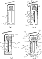
- the figures 3 and 4 illustrate the operation where the extreme low temperature is reached at night, for example in winter. It is therefore generally appropriate to keep the object P warm. This is obtained by means of heating the housing 100 according to the invention.
- the heating by conduction through the wall 116 is supplemented by an electrical resistance 117 in thermal contact with the phase change material 115, which improves the heating efficiency of the phase change material.
- This electrical resistance 117 is connected to the microcontroller 150 and supplied by the photovoltaic cells 141.
- the microcontroller 150 advantageously controls the operation of the electrical resistance as a function of temperature data which it recovers from temperature probes 160 arranged at different locations in the housing.
- phase change material 115 If the outside temperature is sufficient to liquefy the phase change material 115, the latter absorbs heat by changing phase, energy which it will restore at night when the temperature drops.
- the outside day temperature is insufficient in winter to liquefy the phase change material 115.
- the electrical resistance supplied by the photovoltaic cells makes it possible to heat by Joule effect the material with change of phase and to liquefy, during the day.
- the phase change material will return heat to the object overnight, returning to the solid state.
- the electrical resistance supplied by the photovoltaic cells heats the phase change material 115 which liquefies.
- the phase change material 115 is then available to temper the air inside the housing overnight.
- phase change material 115 solidifies, returning heat to the air. The latter then naturally rises to the stored object P (arrow F1).
- the figures 6 to 13 illustrate several variants of the preferred embodiment of a means for heating the phase change material, with optimum efficiency.
- the regulation chamber 110 is provided with glazing 118 on the face of the chamber 110 which is exposed to the sun in the position of use.
- the box according to the invention comprises a heat capture plate 119 covering the volume of phase change material 115.
- the phase change material can be covered with a conductive envelope heat painted black 221 (see figure 8 ).
- the glazing 118 and the heat capture plate 119 constitute a heating system of the "tornado" type of the phase change material 115.
- the “Trombe” type heating system placed on the housing 100 makes it possible to capture the solar radiation and to convert it into heat: the black surface of the plate 119 or of the envelope 221 absorbs the solar radiation, converting it directly into heat and transfer to the phase change material 115 (arrows F5).
- the black surface radiates in the infrared and this radiation blocked by the greenhouse effect by the glazing (arrow F6) is used in part to directly heat the object P and for the rest to store heat in the material to be phase change 115 by liquefying it.
- the latter is then functional for the night ( figure 7 ), during which it will solidify progressively by restoring heat to the air inside the regulation chamber 110 (arrows F7).
- a natural convection movement then sets in, and the hot air rises in the storage chamber 101 to maintain the object P at a prescribed storage temperature.
- the volume of phase change material is supported by the pipe wall 114.
- the determined volume of phase change material is fixed at a distance from the pipe wall 114, so as to provide a double air circulation circuit on either side of the volume of phase change material.
- the volume of phase change material 115 is supported by a wall 116 of the lower regulation chamber 110, facing and at a distance from the glazing 118, so as to provide a double air circulation circuit. on either side of the volume of phase change material.
- This variant is illustrated in figures 8 to 13 .
- the wall 116 which delimits the regulation chamber is not thermal conductive.
- the regulation chamber 210 of the housing 200 comprises a wall 216 provided with glazing 118 on a face intended to be exposed to the sun.
- the determined volume of phase change material 115 is fixed at a distance from the wall 216 which carries it, so as to provide a double air circulation circuit on either side of the volume of phase change material. This preferred arrangement maximizes the heat exchange efficiency and the operation of the housing.
- phase change material 115 is also covered with a heat capture plate 221, here in the form of a complete envelope, but only the face arranged opposite the glazing could be alone covered.
- This embodiment also illustrates the advantageous possibility of equipping each of the air passage orifices separating the regulation chamber 210 from the storage chamber 201 with a controllable hatch, respectively 213a and 213b between an open position allowing passage of air and a closed position blocking the passage of air.
- the closed position is illustrated by a crossed-out rectangle and the open position by a solid rectangle.
- the housing 200 is equipped with fans 130 controllable by the microcontroller 150 in order to generate air flows in a desired direction.
- the fans can be reversed to reverse the direction of the air flow.
- controllable hatches 213a and 213b are themselves equipped with reversible fans, which makes the air exchanges between the storage chamber and the regulation chamber more efficient and more precise.
- controllable air inlet / outlet ports between the inside and the outside of the housing 200: two air inlet / outlet ports 230 and 231 in the storage chamber. , and an air inlet / outlet port 232 in the regulation chamber.
- the air inlet / outlet orifices 230 and 231 are arranged on either side of the stored object and of its support so as to promote air circulation around the object.
- the closed position is illustrated by a crossed-out rectangle and the open position by a solid rectangle.
- controllable hatches and the controllable air inlet / outlet ports are either electrically controlled by the microcontroller, or mechanically controlled depending on the temperature conditions.
- phase change material is advantageously combined with a divided heat conducting material, such as graphite.
- the phase change material 115 is also advantageously in thermal contact with an electrical resistor 117 supplied by the microcontroller 150 as a function of the temperature and humidity conditions sensed by various electronic control equipment 160 incorporated in the housing, for example: a probe of temperature, a sensor humidity sensor, a stored object status sensor (For example an optical sensor used to control the operating status of a stored defibrillator or a gas sensor), a dry contact, or an assortment of these this.
- a probe of temperature for example: a sensor humidity sensor, a stored object status sensor (For example an optical sensor used to control the operating status of a stored defibrillator or a gas sensor), a dry contact, or an assortment of these this.
- the assembly is supplied by a panel of photovoltaic cells 141 connected to a battery 140 itself connected to the microcontroller 150.
- the figure 9 illustrates the operation of the figure 8 in different situations.
- the objective is therefore to limit the heating of the object.
- the hatches 213a and 213b close, and the air inlet / outlet openings 230 and 231 open to allow circulation outside air around the object (arrow F8) in the storage chamber 201 by natural convection.
- a given threshold temperature for example the outside temperature
- the invention provides that the inlet / outlet orifice 231 is arranged at a lower height than the inlet / outlet orifice 230.
- the hot air (heated by the radiation of the sun) therefore exits through this last (arrow F9), and the cooler air from the outside enters through port 231 (arrow F10).
- the inlet / outlet ports 230-231 are arranged opposite to the object, thereby forcing the passage of air around the object.
- the regulation chamber is isolated from the storage chamber because the hatches 213a and 213b are closed.
- the light radiation passes through the glazing and heats the phase change material, as explained above.
- the latter therefore stores heat which it can retransmit later.
- This situation also occurs during a winter day, when the radiation strongly heats the storage chamber but the outside air is cool. In this case, the radiation charges the phase change material with heat for the night (to heat the object). During the day, the object is cooled by the circulation of fresh outside air.
- the figure 10 illustrates the operation of the figure 8 , for example during a summer night: no solar radiation and temperature decreasing. The objective remains to refresh the object.
- the upper inlet / outlet orifice 230 is open, while the lower inlet / outlet orifice 231 is closed.
- the inlet / outlet port 232 of the regulation chamber, arranged in the air column opposite the air column in which the volume of phase change material is located, is open.
- the hatch 213a opening into the air column in which the volume of phase change material is located, is open, while the hatch 213b opening into the air column opposite the air column in which is located the volume of phase change material is closed.
- the air circulation is forced by the actuation of the fans 130, so that the outside air enters the housing through the orifice 230 (arrow F11), circulates around the object while cooling it (arrow F12), and enters the regulation chamber through the hatch 213a (arrow F13).
- the fans are powered by the battery charged during the day by solar panels
- the outside air cools the phase change material (arrow F14) which changes phase as it solidifies. In doing so, it heats the air which is evacuated through the orifice 232 (arrow F15) because it cannot go up towards the object since the hatch 213b is closed.
- the Figures 11 and 12 illustrate the operation of the figure 8 during the cold period, during which the objective is to warm the object.
- the figure 11 illustrates the operation during the day during which the box receives a light radiation.
- the inlet / outlet ports 230, 231 and 232 are closed.
- the daytime outside temperature remains below the phase change temperature of the phase change material.
- the light radiation transmitted by the glazing heats up the phase change material which stores heat by changing phase.
- the air heats up on contact with the phase change material: between the phase change material and the glazing (arrow F16), and between the phase change material and the pipe wall 114 (arrow F17).
- the air cools in contact with the object and descends into the regulation chamber through the open hatch 213b (arrow F20), opening in the air column opposite the air column in which the volume of phase change material is located.
- phase change material can be supplemented by supplying the resistor 117.
- a phase change material combined with a material divided heat conductor to improve heat transfer efficiency and achieve desired storage / destocking power.
- the 230-231 inlet / outlet ports may be temporarily opened.
- the figure 12 illustrates the operation during the night during which the housing no longer receives any light radiation.
- the upper arrangement of the storage chamber with respect to the regulation chamber in the lower position allows natural convection of the air under certain temperature conditions. This arrangement is particularly advantageous when it is possible to install such a housing.
- thermo-regulated it may be desirable to modify a pre-existing safe storing an object to be thermo-regulated in order, for example, to reduce the energy consumption used for this thermal regulation.
- the figure 13 illustrates a first possible arrangement for forming a box 300 according to the invention from a pre-existing storage chamber 301.
- a regulation chamber 310 according to the invention is arranged laterally with respect to the storage chamber 301.
- the figure 14 illustrates a second possible arrangement for forming a housing 400 according to the invention from a pre-existing storage chamber 401.
- a regulation chamber 410 according to the invention is arranged above with respect to the storage chamber 401.
- the storage chamber will also be pierced with air inlet / outlet openings.
- the operation and / or the remote control can / can be ensured thanks to the microcontroller 150 and to electronic sensors 160, such as temperature probes as well as sensors of relative humidity and various dry contacts, arranged at each component of the housing according to the invention (phase change material 115, air columns, storage chamber 101, exterior surface).
- electronic sensors 160 such as temperature probes as well as sensors of relative humidity and various dry contacts, arranged at each component of the housing according to the invention (phase change material 115, air columns, storage chamber 101, exterior surface).
- the box according to the invention also advantageously comprises a telecommunication module making it possible in particular to remotely monitor the temperatures recorded at each level of the components by the temperature sensors 160.
- the microcontroller 150 is advantageously equipped with a communication system comprising a transmitter / receiver 151 of wireless link, preferably LRWA (Long Range Wild Area) type with low energy consumption.
- LRWA Long Range Wild Area
- transceiver 151 is capable of transmitting and receiving data over a wireless wide area network with low energy consumption, called “LPWAN” and / or over a wireless local area network with low energy consumption, called “LPLAN”. .
- LPWAN wireless wide area network with low energy consumption
- LPLAN wireless local area network with low energy consumption
- the transmitter / receiver 151 is capable of transmitting and receiving according to the proven communication protocols and frequently used in so-called “IoT” networks. These communication methods are low speed, long range and very energy efficient.
- an electronic card specifically adapted for monitoring content and communicating through LRWA networks can guarantee permanent monitoring of the environment and its state.
- a “cloud” type server makes it possible to supervise a set of boxes according to the invention, geolocated on a map, and to individually access each of the boxes and the reading of data from all the electronic control equipment 160 such as the temperature probes, the hygrometric sensors and the dry contacts stored on a memory (not shown) connected to the microcontroller 150.
- the solution according to the invention makes it possible to dispense with all sources of energy external to the housing other than its immediate external environment and sources of renewable energy such as solar, and to avoid the use of fossil energies or chemical materials to be recharged.
- the invention allows the device to be protected from temperature constraints (variations) encountered between day and night but also summer and winter (when the content is limited at high and low temperatures).
- Such a device eliminates the need for energy recharging and remains operational over a multi-year period without loss of efficiency.
- the dimensions of the housing and of its components, the choice of the phase change material and the possible addition of a divided heat conducting material and / or an electrical resistance, may vary depending on the product to be stored (the nature renewable energy requested can also vary: we can use solar and / or surface geothermal energy).
Landscapes
- Engineering & Computer Science (AREA)
- Chemical & Material Sciences (AREA)
- Chemical Kinetics & Catalysis (AREA)
- Electrochemistry (AREA)
- General Chemical & Material Sciences (AREA)
- Manufacturing & Machinery (AREA)
- Life Sciences & Earth Sciences (AREA)
- Health & Medical Sciences (AREA)
- Physics & Mathematics (AREA)
- General Engineering & Computer Science (AREA)
- Mechanical Engineering (AREA)
- Surgery (AREA)
- Thermal Sciences (AREA)
- Nuclear Medicine, Radiotherapy & Molecular Imaging (AREA)
- Public Health (AREA)
- Sustainable Development (AREA)
- Biomedical Technology (AREA)
- Heart & Thoracic Surgery (AREA)
- Medical Informatics (AREA)
- Molecular Biology (AREA)
- Animal Behavior & Ethology (AREA)
- General Health & Medical Sciences (AREA)
- Sustainable Energy (AREA)
- Veterinary Medicine (AREA)
- Combustion & Propulsion (AREA)
- Devices That Are Associated With Refrigeration Equipment (AREA)
- Packages (AREA)
- Control Of Vending Devices And Auxiliary Devices For Vending Devices (AREA)
- Building Environments (AREA)
- Cooling Or The Like Of Electrical Apparatus (AREA)
Applications Claiming Priority (1)
| Application Number | Priority Date | Filing Date | Title |
|---|---|---|---|
| FR1801050A FR3087003B1 (fr) | 2018-10-04 | 2018-10-04 | Boîtier themo-regule autonome |
Publications (2)
| Publication Number | Publication Date |
|---|---|
| EP3633304A1 true EP3633304A1 (de) | 2020-04-08 |
| EP3633304B1 EP3633304B1 (de) | 2020-12-09 |
Family
ID=65243635
Family Applications (1)
| Application Number | Title | Priority Date | Filing Date |
|---|---|---|---|
| EP19199574.5A Active EP3633304B1 (de) | 2018-10-04 | 2019-09-25 | Autonomes wärmereguliertes gehäuse |
Country Status (4)
| Country | Link |
|---|---|
| EP (1) | EP3633304B1 (de) |
| ES (1) | ES2859498T3 (de) |
| FR (1) | FR3087003B1 (de) |
| WO (1) | WO2020069947A1 (de) |
Cited By (1)
| Publication number | Priority date | Publication date | Assignee | Title |
|---|---|---|---|---|
| WO2021219546A1 (en) * | 2020-04-27 | 2021-11-04 | Trisult Holding B.V. | Portable aed case |
Citations (3)
| Publication number | Priority date | Publication date | Assignee | Title |
|---|---|---|---|---|
| US4928501A (en) * | 1988-03-17 | 1990-05-29 | Sanden Corporation | Cold preserving container |
| US20160243000A1 (en) * | 2013-10-17 | 2016-08-25 | David Gray | A portable temperature controlled container |
| US20180133495A1 (en) * | 2016-11-17 | 2018-05-17 | Alan Himelfarb | System and methods for storing an automated external defibrillator |
-
2018
- 2018-10-04 FR FR1801050A patent/FR3087003B1/fr active Active
-
2019
- 2019-09-25 WO PCT/EP2019/075957 patent/WO2020069947A1/fr active Application Filing
- 2019-09-25 EP EP19199574.5A patent/EP3633304B1/de active Active
- 2019-09-25 ES ES19199574T patent/ES2859498T3/es active Active
Patent Citations (3)
| Publication number | Priority date | Publication date | Assignee | Title |
|---|---|---|---|---|
| US4928501A (en) * | 1988-03-17 | 1990-05-29 | Sanden Corporation | Cold preserving container |
| US20160243000A1 (en) * | 2013-10-17 | 2016-08-25 | David Gray | A portable temperature controlled container |
| US20180133495A1 (en) * | 2016-11-17 | 2018-05-17 | Alan Himelfarb | System and methods for storing an automated external defibrillator |
Cited By (1)
| Publication number | Priority date | Publication date | Assignee | Title |
|---|---|---|---|---|
| WO2021219546A1 (en) * | 2020-04-27 | 2021-11-04 | Trisult Holding B.V. | Portable aed case |
Also Published As
| Publication number | Publication date |
|---|---|
| FR3087003A1 (fr) | 2020-04-10 |
| FR3087003B1 (fr) | 2020-10-02 |
| WO2020069947A1 (fr) | 2020-04-09 |
| EP3633304B1 (de) | 2020-12-09 |
| ES2859498T3 (es) | 2021-10-04 |
Similar Documents
| Publication | Publication Date | Title |
|---|---|---|
| US20150083180A1 (en) | Systems, methods and/or apparatus for thermoelectric energy generation | |
| CA2955881A1 (fr) | Dispositif et procede pour le stockage d'energie thermique | |
| FR2471562A1 (fr) | Dispositif modulaire pour effectuer un chauffage ou un refroidissement a partir de l'energie solaire par un cycle intermittent de pompe a chaleur a adsorption, et appareil compose de tels dispositifs | |
| KR20140101805A (ko) | 열전기 에너지 발전을 위한 시스템, 방법 및/또는 장치 | |
| WO2010004131A2 (fr) | Procède et dispositif de régulation thermique d'une batterie rechargeable de stockage d'énergie électrique | |
| EP3633304B1 (de) | Autonomes wärmereguliertes gehäuse | |
| EP3274639B1 (de) | Solare einrichtung zur autonomen adsorptionskälteherstellung | |
| EP3925014A2 (de) | Thermoelektrische vorrichtung mit seebeck-effekt | |
| EP2366845B1 (de) | Aktives Wärmedämmungsverfahren und Vorrichtung zur Umsetzung dieses Verfahrens | |
| FR2864174A1 (fr) | Centrale electrique mobile, utilisant l'air comprime pour stocker l'energie puis l'action de la poussee d'archimede sur une roue pour sa recuperation | |
| BE1026401B1 (fr) | Dispositif pour la regulation de la temperature dans une enceinte | |
| EP3571963B1 (de) | Wärmeregulierbare vorrichtung zum empfang und zur aufbewahrung eines paketes, und diese vorrichtung umfassendes system | |
| WO2011080490A2 (fr) | Dispositif de chauffage central solaire a accumulation d'energie | |
| EP0878668B1 (de) | Konvektionsheizungsgerät mit natürlichem Zug für umkehrbare Klimaanlage | |
| FR3048767A1 (fr) | Barriere thermique et element interieur de stockage thermique | |
| WO2020115428A1 (fr) | Batterie modulaire comprenant un systeme de conditionnement thermique | |
| WO2015186100A1 (fr) | Installation de conversion de chaleur en energie mecanique a systeme de refroidissement du fluide de travail ameliore | |
| FR3047022A1 (fr) | Element d'enveloppe de batiment comprenant un materiau a changement de phase, et batiment correspondant | |
| EP1401252A1 (de) | Gekühlter Elektronikschrank, insbesondere für Fernsprechanlagen | |
| WO2017140326A1 (fr) | Unite autonome de production electrique de puissance superieure a 150 kwp d'un champ de panneaux photovoltaiques, contenue dans un «schelter», destinee a des implantations dans des pays chauds, sans necessite de disposer de sources d'alimentation via un reseau electrique et sans nuire au rendement de la production energetique solaire | |
| FR3005145A1 (fr) | Dispositif de chauffage et/ou de rafraichissement a paroi ayant un capteur thermique solaire et un element de stockage d'energie thermique | |
| FR3017199A1 (fr) | Dispositif solaire de transfert de chaleur | |
| FR2993348A1 (fr) | Dispositif d'optimisation des performances d'une pompe a chaleur en periode hivernale, par stockage d'energie en sol profond | |
| FR3140419A1 (fr) | Système physique de batterie à air comprimé | |
| CH701001B1 (fr) | Citerne solaire. |
Legal Events
| Date | Code | Title | Description |
|---|---|---|---|
| PUAI | Public reference made under article 153(3) epc to a published international application that has entered the european phase |
Free format text: ORIGINAL CODE: 0009012 |
|
| STAA | Information on the status of an ep patent application or granted ep patent |
Free format text: STATUS: THE APPLICATION HAS BEEN PUBLISHED |
|
| AK | Designated contracting states |
Kind code of ref document: A1 Designated state(s): AL AT BE BG CH CY CZ DE DK EE ES FI FR GB GR HR HU IE IS IT LI LT LU LV MC MK MT NL NO PL PT RO RS SE SI SK SM TR |
|
| AX | Request for extension of the european patent |
Extension state: BA ME |
|
| STAA | Information on the status of an ep patent application or granted ep patent |
Free format text: STATUS: REQUEST FOR EXAMINATION WAS MADE |
|
| 17P | Request for examination filed |
Effective date: 20200423 |
|
| RBV | Designated contracting states (corrected) |
Designated state(s): AL AT BE BG CH CY CZ DE DK EE ES FI FR GB GR HR HU IE IS IT LI LT LU LV MC MK MT NL NO PL PT RO RS SE SI SK SM TR |
|
| GRAP | Despatch of communication of intention to grant a patent |
Free format text: ORIGINAL CODE: EPIDOSNIGR1 |
|
| STAA | Information on the status of an ep patent application or granted ep patent |
Free format text: STATUS: GRANT OF PATENT IS INTENDED |
|
| INTG | Intention to grant announced |
Effective date: 20200707 |
|
| GRAS | Grant fee paid |
Free format text: ORIGINAL CODE: EPIDOSNIGR3 |
|
| GRAA | (expected) grant |
Free format text: ORIGINAL CODE: 0009210 |
|
| STAA | Information on the status of an ep patent application or granted ep patent |
Free format text: STATUS: THE PATENT HAS BEEN GRANTED |
|
| AK | Designated contracting states |
Kind code of ref document: B1 Designated state(s): AL AT BE BG CH CY CZ DE DK EE ES FI FR GB GR HR HU IE IS IT LI LT LU LV MC MK MT NL NO PL PT RO RS SE SI SK SM TR |
|
| REG | Reference to a national code |
Ref country code: GB Ref legal event code: FG4D Free format text: NOT ENGLISH |
|
| REG | Reference to a national code |
Ref country code: CH Ref legal event code: EP Ref country code: AT Ref legal event code: REF Ref document number: 1343876 Country of ref document: AT Kind code of ref document: T Effective date: 20201215 |
|
| REG | Reference to a national code |
Ref country code: DE Ref legal event code: R096 Ref document number: 602019001663 Country of ref document: DE |
|
| REG | Reference to a national code |
Ref country code: IE Ref legal event code: FG4D Free format text: LANGUAGE OF EP DOCUMENT: FRENCH |
|
| REG | Reference to a national code |
Ref country code: CH Ref legal event code: NV Representative=s name: GRIFFES CONSULTING SA, CH |
|
| REG | Reference to a national code |
Ref country code: NL Ref legal event code: FP |
|
| PG25 | Lapsed in a contracting state [announced via postgrant information from national office to epo] |
Ref country code: GR Free format text: LAPSE BECAUSE OF FAILURE TO SUBMIT A TRANSLATION OF THE DESCRIPTION OR TO PAY THE FEE WITHIN THE PRESCRIBED TIME-LIMIT Effective date: 20210310 Ref country code: NO Free format text: LAPSE BECAUSE OF FAILURE TO SUBMIT A TRANSLATION OF THE DESCRIPTION OR TO PAY THE FEE WITHIN THE PRESCRIBED TIME-LIMIT Effective date: 20210309 Ref country code: FI Free format text: LAPSE BECAUSE OF FAILURE TO SUBMIT A TRANSLATION OF THE DESCRIPTION OR TO PAY THE FEE WITHIN THE PRESCRIBED TIME-LIMIT Effective date: 20201209 Ref country code: RS Free format text: LAPSE BECAUSE OF FAILURE TO SUBMIT A TRANSLATION OF THE DESCRIPTION OR TO PAY THE FEE WITHIN THE PRESCRIBED TIME-LIMIT Effective date: 20201209 |
|
| REG | Reference to a national code |
Ref country code: AT Ref legal event code: MK05 Ref document number: 1343876 Country of ref document: AT Kind code of ref document: T Effective date: 20201209 |
|
| PG25 | Lapsed in a contracting state [announced via postgrant information from national office to epo] |
Ref country code: BG Free format text: LAPSE BECAUSE OF FAILURE TO SUBMIT A TRANSLATION OF THE DESCRIPTION OR TO PAY THE FEE WITHIN THE PRESCRIBED TIME-LIMIT Effective date: 20210309 Ref country code: SE Free format text: LAPSE BECAUSE OF FAILURE TO SUBMIT A TRANSLATION OF THE DESCRIPTION OR TO PAY THE FEE WITHIN THE PRESCRIBED TIME-LIMIT Effective date: 20201209 Ref country code: LV Free format text: LAPSE BECAUSE OF FAILURE TO SUBMIT A TRANSLATION OF THE DESCRIPTION OR TO PAY THE FEE WITHIN THE PRESCRIBED TIME-LIMIT Effective date: 20201209 |
|
| PG25 | Lapsed in a contracting state [announced via postgrant information from national office to epo] |
Ref country code: HR Free format text: LAPSE BECAUSE OF FAILURE TO SUBMIT A TRANSLATION OF THE DESCRIPTION OR TO PAY THE FEE WITHIN THE PRESCRIBED TIME-LIMIT Effective date: 20201209 |
|
| REG | Reference to a national code |
Ref country code: LT Ref legal event code: MG9D |
|
| PG25 | Lapsed in a contracting state [announced via postgrant information from national office to epo] |
Ref country code: CZ Free format text: LAPSE BECAUSE OF FAILURE TO SUBMIT A TRANSLATION OF THE DESCRIPTION OR TO PAY THE FEE WITHIN THE PRESCRIBED TIME-LIMIT Effective date: 20201209 Ref country code: EE Free format text: LAPSE BECAUSE OF FAILURE TO SUBMIT A TRANSLATION OF THE DESCRIPTION OR TO PAY THE FEE WITHIN THE PRESCRIBED TIME-LIMIT Effective date: 20201209 Ref country code: SM Free format text: LAPSE BECAUSE OF FAILURE TO SUBMIT A TRANSLATION OF THE DESCRIPTION OR TO PAY THE FEE WITHIN THE PRESCRIBED TIME-LIMIT Effective date: 20201209 Ref country code: SK Free format text: LAPSE BECAUSE OF FAILURE TO SUBMIT A TRANSLATION OF THE DESCRIPTION OR TO PAY THE FEE WITHIN THE PRESCRIBED TIME-LIMIT Effective date: 20201209 Ref country code: LT Free format text: LAPSE BECAUSE OF FAILURE TO SUBMIT A TRANSLATION OF THE DESCRIPTION OR TO PAY THE FEE WITHIN THE PRESCRIBED TIME-LIMIT Effective date: 20201209 Ref country code: PT Free format text: LAPSE BECAUSE OF FAILURE TO SUBMIT A TRANSLATION OF THE DESCRIPTION OR TO PAY THE FEE WITHIN THE PRESCRIBED TIME-LIMIT Effective date: 20210409 Ref country code: RO Free format text: LAPSE BECAUSE OF FAILURE TO SUBMIT A TRANSLATION OF THE DESCRIPTION OR TO PAY THE FEE WITHIN THE PRESCRIBED TIME-LIMIT Effective date: 20201209 |
|
| PG25 | Lapsed in a contracting state [announced via postgrant information from national office to epo] |
Ref country code: AT Free format text: LAPSE BECAUSE OF FAILURE TO SUBMIT A TRANSLATION OF THE DESCRIPTION OR TO PAY THE FEE WITHIN THE PRESCRIBED TIME-LIMIT Effective date: 20201209 Ref country code: PL Free format text: LAPSE BECAUSE OF FAILURE TO SUBMIT A TRANSLATION OF THE DESCRIPTION OR TO PAY THE FEE WITHIN THE PRESCRIBED TIME-LIMIT Effective date: 20201209 |
|
| REG | Reference to a national code |
Ref country code: DE Ref legal event code: R097 Ref document number: 602019001663 Country of ref document: DE |
|
| PG25 | Lapsed in a contracting state [announced via postgrant information from national office to epo] |
Ref country code: IS Free format text: LAPSE BECAUSE OF FAILURE TO SUBMIT A TRANSLATION OF THE DESCRIPTION OR TO PAY THE FEE WITHIN THE PRESCRIBED TIME-LIMIT Effective date: 20210409 |
|
| REG | Reference to a national code |
Ref country code: ES Ref legal event code: FG2A Ref document number: 2859498 Country of ref document: ES Kind code of ref document: T3 Effective date: 20211004 |
|
| PLBE | No opposition filed within time limit |
Free format text: ORIGINAL CODE: 0009261 |
|
| STAA | Information on the status of an ep patent application or granted ep patent |
Free format text: STATUS: NO OPPOSITION FILED WITHIN TIME LIMIT |
|
| PG25 | Lapsed in a contracting state [announced via postgrant information from national office to epo] |
Ref country code: AL Free format text: LAPSE BECAUSE OF FAILURE TO SUBMIT A TRANSLATION OF THE DESCRIPTION OR TO PAY THE FEE WITHIN THE PRESCRIBED TIME-LIMIT Effective date: 20201209 |
|
| 26N | No opposition filed |
Effective date: 20210910 |
|
| PG25 | Lapsed in a contracting state [announced via postgrant information from national office to epo] |
Ref country code: SI Free format text: LAPSE BECAUSE OF FAILURE TO SUBMIT A TRANSLATION OF THE DESCRIPTION OR TO PAY THE FEE WITHIN THE PRESCRIBED TIME-LIMIT Effective date: 20201209 Ref country code: DK Free format text: LAPSE BECAUSE OF FAILURE TO SUBMIT A TRANSLATION OF THE DESCRIPTION OR TO PAY THE FEE WITHIN THE PRESCRIBED TIME-LIMIT Effective date: 20201209 |
|
| PG25 | Lapsed in a contracting state [announced via postgrant information from national office to epo] |
Ref country code: IS Free format text: LAPSE BECAUSE OF FAILURE TO SUBMIT A TRANSLATION OF THE DESCRIPTION OR TO PAY THE FEE WITHIN THE PRESCRIBED TIME-LIMIT Effective date: 20210409 Ref country code: MC Free format text: LAPSE BECAUSE OF FAILURE TO SUBMIT A TRANSLATION OF THE DESCRIPTION OR TO PAY THE FEE WITHIN THE PRESCRIBED TIME-LIMIT Effective date: 20201209 |
|
| PG25 | Lapsed in a contracting state [announced via postgrant information from national office to epo] |
Ref country code: IE Free format text: LAPSE BECAUSE OF NON-PAYMENT OF DUE FEES Effective date: 20210925 |
|
| PGFP | Annual fee paid to national office [announced via postgrant information from national office to epo] |
Ref country code: CH Payment date: 20220927 Year of fee payment: 4 |
|
| PG25 | Lapsed in a contracting state [announced via postgrant information from national office to epo] |
Ref country code: CY Free format text: LAPSE BECAUSE OF FAILURE TO SUBMIT A TRANSLATION OF THE DESCRIPTION OR TO PAY THE FEE WITHIN THE PRESCRIBED TIME-LIMIT Effective date: 20201209 |
|
| PG25 | Lapsed in a contracting state [announced via postgrant information from national office to epo] |
Ref country code: HU Free format text: LAPSE BECAUSE OF FAILURE TO SUBMIT A TRANSLATION OF THE DESCRIPTION OR TO PAY THE FEE WITHIN THE PRESCRIBED TIME-LIMIT; INVALID AB INITIO Effective date: 20190925 |
|
| PGFP | Annual fee paid to national office [announced via postgrant information from national office to epo] |
Ref country code: NL Payment date: 20230926 Year of fee payment: 5 Ref country code: LU Payment date: 20230929 Year of fee payment: 5 Ref country code: GB Payment date: 20230926 Year of fee payment: 5 |
|
| PGFP | Annual fee paid to national office [announced via postgrant information from national office to epo] |
Ref country code: FR Payment date: 20230918 Year of fee payment: 5 Ref country code: DE Payment date: 20230930 Year of fee payment: 5 Ref country code: BE Payment date: 20230925 Year of fee payment: 5 |
|
| PGFP | Annual fee paid to national office [announced via postgrant information from national office to epo] |
Ref country code: ES Payment date: 20231002 Year of fee payment: 5 |
|
| PGFP | Annual fee paid to national office [announced via postgrant information from national office to epo] |
Ref country code: IT Payment date: 20230927 Year of fee payment: 5 |
|
| PG25 | Lapsed in a contracting state [announced via postgrant information from national office to epo] |
Ref country code: MK Free format text: LAPSE BECAUSE OF FAILURE TO SUBMIT A TRANSLATION OF THE DESCRIPTION OR TO PAY THE FEE WITHIN THE PRESCRIBED TIME-LIMIT Effective date: 20201209 |
|
| REG | Reference to a national code |
Ref country code: CH Ref legal event code: PL |