EP3633230A1 - Active-type vibration-damping device and method for controlling active-type vibration-damping device - Google Patents
Active-type vibration-damping device and method for controlling active-type vibration-damping device Download PDFInfo
- Publication number
- EP3633230A1 EP3633230A1 EP18806340.8A EP18806340A EP3633230A1 EP 3633230 A1 EP3633230 A1 EP 3633230A1 EP 18806340 A EP18806340 A EP 18806340A EP 3633230 A1 EP3633230 A1 EP 3633230A1
- Authority
- EP
- European Patent Office
- Prior art keywords
- rod body
- feedback control
- vibration device
- acceleration
- active anti
- Prior art date
- Legal status (The legal status is an assumption and is not a legal conclusion. Google has not performed a legal analysis and makes no representation as to the accuracy of the status listed.)
- Granted
Links
Images




Classifications
-
- F—MECHANICAL ENGINEERING; LIGHTING; HEATING; WEAPONS; BLASTING
- F16—ENGINEERING ELEMENTS AND UNITS; GENERAL MEASURES FOR PRODUCING AND MAINTAINING EFFECTIVE FUNCTIONING OF MACHINES OR INSTALLATIONS; THERMAL INSULATION IN GENERAL
- F16F—SPRINGS; SHOCK-ABSORBERS; MEANS FOR DAMPING VIBRATION
- F16F7/00—Vibration-dampers; Shock-absorbers
- F16F7/10—Vibration-dampers; Shock-absorbers using inertia effect
- F16F7/1005—Vibration-dampers; Shock-absorbers using inertia effect characterised by active control of the mass
- F16F7/1011—Vibration-dampers; Shock-absorbers using inertia effect characterised by active control of the mass by electromagnetic means
-
- B—PERFORMING OPERATIONS; TRANSPORTING
- B60—VEHICLES IN GENERAL
- B60K—ARRANGEMENT OR MOUNTING OF PROPULSION UNITS OR OF TRANSMISSIONS IN VEHICLES; ARRANGEMENT OR MOUNTING OF PLURAL DIVERSE PRIME-MOVERS IN VEHICLES; AUXILIARY DRIVES FOR VEHICLES; INSTRUMENTATION OR DASHBOARDS FOR VEHICLES; ARRANGEMENTS IN CONNECTION WITH COOLING, AIR INTAKE, GAS EXHAUST OR FUEL SUPPLY OF PROPULSION UNITS IN VEHICLES
- B60K5/00—Arrangement or mounting of internal-combustion or jet-propulsion units
- B60K5/12—Arrangement of engine supports
- B60K5/1283—Adjustable supports, e.g. the mounting or the characteristics being adjustable
-
- B—PERFORMING OPERATIONS; TRANSPORTING
- B60—VEHICLES IN GENERAL
- B60K—ARRANGEMENT OR MOUNTING OF PROPULSION UNITS OR OF TRANSMISSIONS IN VEHICLES; ARRANGEMENT OR MOUNTING OF PLURAL DIVERSE PRIME-MOVERS IN VEHICLES; AUXILIARY DRIVES FOR VEHICLES; INSTRUMENTATION OR DASHBOARDS FOR VEHICLES; ARRANGEMENTS IN CONNECTION WITH COOLING, AIR INTAKE, GAS EXHAUST OR FUEL SUPPLY OF PROPULSION UNITS IN VEHICLES
- B60K5/00—Arrangement or mounting of internal-combustion or jet-propulsion units
- B60K5/12—Arrangement of engine supports
-
- B—PERFORMING OPERATIONS; TRANSPORTING
- B60—VEHICLES IN GENERAL
- B60K—ARRANGEMENT OR MOUNTING OF PROPULSION UNITS OR OF TRANSMISSIONS IN VEHICLES; ARRANGEMENT OR MOUNTING OF PLURAL DIVERSE PRIME-MOVERS IN VEHICLES; AUXILIARY DRIVES FOR VEHICLES; INSTRUMENTATION OR DASHBOARDS FOR VEHICLES; ARRANGEMENTS IN CONNECTION WITH COOLING, AIR INTAKE, GAS EXHAUST OR FUEL SUPPLY OF PROPULSION UNITS IN VEHICLES
- B60K5/00—Arrangement or mounting of internal-combustion or jet-propulsion units
- B60K5/12—Arrangement of engine supports
- B60K5/1208—Resilient supports
-
- F—MECHANICAL ENGINEERING; LIGHTING; HEATING; WEAPONS; BLASTING
- F16—ENGINEERING ELEMENTS AND UNITS; GENERAL MEASURES FOR PRODUCING AND MAINTAINING EFFECTIVE FUNCTIONING OF MACHINES OR INSTALLATIONS; THERMAL INSULATION IN GENERAL
- F16F—SPRINGS; SHOCK-ABSORBERS; MEANS FOR DAMPING VIBRATION
- F16F13/00—Units comprising springs of the non-fluid type as well as vibration-dampers, shock-absorbers, or fluid springs
- F16F13/04—Units comprising springs of the non-fluid type as well as vibration-dampers, shock-absorbers, or fluid springs comprising both a plastics spring and a damper, e.g. a friction damper
- F16F13/26—Units comprising springs of the non-fluid type as well as vibration-dampers, shock-absorbers, or fluid springs comprising both a plastics spring and a damper, e.g. a friction damper characterised by adjusting or regulating devices responsive to exterior conditions
-
- F—MECHANICAL ENGINEERING; LIGHTING; HEATING; WEAPONS; BLASTING
- F16—ENGINEERING ELEMENTS AND UNITS; GENERAL MEASURES FOR PRODUCING AND MAINTAINING EFFECTIVE FUNCTIONING OF MACHINES OR INSTALLATIONS; THERMAL INSULATION IN GENERAL
- F16F—SPRINGS; SHOCK-ABSORBERS; MEANS FOR DAMPING VIBRATION
- F16F15/00—Suppression of vibrations in systems; Means or arrangements for avoiding or reducing out-of-balance forces, e.g. due to motion
- F16F15/02—Suppression of vibrations of non-rotating, e.g. reciprocating systems; Suppression of vibrations of rotating systems by use of members not moving with the rotating systems
- F16F15/022—Suppression of vibrations of non-rotating, e.g. reciprocating systems; Suppression of vibrations of rotating systems by use of members not moving with the rotating systems using dampers and springs in combination
-
- F—MECHANICAL ENGINEERING; LIGHTING; HEATING; WEAPONS; BLASTING
- F16—ENGINEERING ELEMENTS AND UNITS; GENERAL MEASURES FOR PRODUCING AND MAINTAINING EFFECTIVE FUNCTIONING OF MACHINES OR INSTALLATIONS; THERMAL INSULATION IN GENERAL
- F16F—SPRINGS; SHOCK-ABSORBERS; MEANS FOR DAMPING VIBRATION
- F16F2222/00—Special physical effects, e.g. nature of damping effects
- F16F2222/08—Inertia
-
- F—MECHANICAL ENGINEERING; LIGHTING; HEATING; WEAPONS; BLASTING
- F16—ENGINEERING ELEMENTS AND UNITS; GENERAL MEASURES FOR PRODUCING AND MAINTAINING EFFECTIVE FUNCTIONING OF MACHINES OR INSTALLATIONS; THERMAL INSULATION IN GENERAL
- F16F—SPRINGS; SHOCK-ABSORBERS; MEANS FOR DAMPING VIBRATION
- F16F2228/00—Functional characteristics, e.g. variability, frequency-dependence
- F16F2228/06—Stiffness
- F16F2228/066—Variable stiffness
-
- F—MECHANICAL ENGINEERING; LIGHTING; HEATING; WEAPONS; BLASTING
- F16—ENGINEERING ELEMENTS AND UNITS; GENERAL MEASURES FOR PRODUCING AND MAINTAINING EFFECTIVE FUNCTIONING OF MACHINES OR INSTALLATIONS; THERMAL INSULATION IN GENERAL
- F16F—SPRINGS; SHOCK-ABSORBERS; MEANS FOR DAMPING VIBRATION
- F16F2230/00—Purpose; Design features
- F16F2230/0047—Measuring, indicating
-
- F—MECHANICAL ENGINEERING; LIGHTING; HEATING; WEAPONS; BLASTING
- F16—ENGINEERING ELEMENTS AND UNITS; GENERAL MEASURES FOR PRODUCING AND MAINTAINING EFFECTIVE FUNCTIONING OF MACHINES OR INSTALLATIONS; THERMAL INSULATION IN GENERAL
- F16F—SPRINGS; SHOCK-ABSORBERS; MEANS FOR DAMPING VIBRATION
- F16F2230/00—Purpose; Design features
- F16F2230/08—Sensor arrangement
-
- F—MECHANICAL ENGINEERING; LIGHTING; HEATING; WEAPONS; BLASTING
- F16—ENGINEERING ELEMENTS AND UNITS; GENERAL MEASURES FOR PRODUCING AND MAINTAINING EFFECTIVE FUNCTIONING OF MACHINES OR INSTALLATIONS; THERMAL INSULATION IN GENERAL
- F16F—SPRINGS; SHOCK-ABSORBERS; MEANS FOR DAMPING VIBRATION
- F16F2230/00—Purpose; Design features
- F16F2230/18—Control arrangements
Definitions
- the present disclosure relates to an anti-vibration device and a method of controlling the active-vibration device.
- the anti-vibration performance and the resonance frequency are mainly determined by a mass of a rod body.
- the anti-vibration frequency region on the higher side than the resonance frequency becomes narrow. Therefore, it is necessary to increase the mass of the rod body to reduce the resonance frequency to enlarge the anti-vibration frequency region on the higher side than the resonance frequency. However, this may cause the fuel efficiency of the vehicle to be deteriorated by an amount equivalent to increase in the mass of the rod body. Accordingly, it can be said that an anti-vibration performance equivalent to that in the case where the mass of the rod body is increased is preferably obtained without actually increasing the mass of the rod body.
- the present disclosure has been made to solve the above-described problems, and an object of the present disclosure is to provide an active anti-vibration device capable of achieving an anti-vibration performance equivalent to that in a case where a mass of a rod body differs from an actual mass, and a method of controlling the active anti-vibration device.
- An active anti-vibration device of the present disclosure includes a pair of elastic connecting parts, a rod body that connects the pair of elastic connecting parts, an inertial mass that is supported by the rod body, a drive part that reciprocates the inertial mass in an axial direction of the rod body, and a controller that is configured to be able to perform acceleration feedback control to control the drive part so that a first force proportional to an axial acceleration of the rod body is generated.
- the active anti-vibration device comprising a pair of elastic connecting parts, a rod body that connects the pair of elastic connecting parts, an inertial mass that is supported by the rod body, a drive part that reciprocates the inertial mass in an axial direction of the rod body, and a controller that controls the drive part, the controller performs acceleration feedback control by controlling the drive part so that a first force proportional to an axial acceleration of the rod body is generated.
- an active anti-vibration device capable of achieving an anti-vibration performance equivalent to that in a case where a mass of a rod body differs from an actual mass, and a method of controlling the active anti-vibration device.
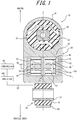
- FIG. 1 is a cross-sectional view illustrating an active anti-vibration device 10 according to the present embodiment.
- FIG. 2 is a main portion cross-sectional view enlarging and illustrating a main portion of the active anti-vibration device of FIG. 1 in an operation state.
- the active anti-vibration device 10 of the present embodiment is structured as a torque rod, and is configured to connect an engine side and a vehicle body side of a vehicle. More specifically, the active anti-vibration device 10 in the illustrated example is suitable for use as an upper torque rod to be connected to the engine mounted to the vehicle body by means of a pendulum mount structure. Note that the active anti-vibration device of the present disclosure may be configured to be connected to the engine by means of a supporting structure other than the pendulum mount structure, or may be configured to be used as a torque rod other than the upper torque rod.
- the active anti-vibration device 10 of the present embodiment includes a pair of elastic connecting parts 20 and 30, a rod body 40 connecting the pair of elastic connecting parts 20 and 30, an actuator 50 disposed in the rod body 40, an accelerometer 80 attached to the rod body 40, a controller 90, and an amplifier 100.
- the rod body 40 integrally includes a first outer cylinder part 41 that accommodates the first elastic connecting part 20 of the pair of elastic connecting parts 20 and 30 at an inner circumferential side of the first outer cylinder part 41, a second outer cylinder part 42 that accommodates the second elastic connecting part 30 at an inner circumferential side of the second outer cylinder part 42, and a middle part 43 that extends straight between the first outer cylinder part 41 and the second outer cylinder part 42.
- an extending direction of a central axis C of the rod body 40 is referred to as an axial direction of the rod body 40 (also simply referred to as an "axial direction").
- the rod body 40 is made of, for example, metal such as iron or aluminum, or resin.
- the first elastic connecting part 20 and the second elastic connecting part 30 include respective inner cylinders 22 and 32 that are disposed at the inner circumferential sides of the first outer cylinder part 41 and the second outer cylinder part 42, respectively, and respective elastic members 23 and 33 that connect inner circumferential surfaces of the first outer cylinder part 41 and the second outer cylinder part 42 and outer circumferential surfaces of inner cylinders 22 and 32, respectively.
- the elastic members 23 and 33 are made of, for example, rubber.
- the first elastic connecting part 20 has an outer diameter larger than the second elastic connecting part 30.
- the first elastic connecting part 20 is configured to be connected to the engine side of the vehicle
- the second elastic connecting part 30 is configured to be connected to the vehicle body side of the vehicle.
- the central axis of the inner cylinder 22 of the first elastic connecting part 20 and the central axis of the inner cylinder 32 of the second elastic connecting part 30 extend in mutually perpendicular directions, but the directional relation between these central axes is not limited thereto, and, for example, both may extend in parallel to each other.
- the actuator 50 is disposed in a recess 44 formed in the rod body 40.
- the actuator 50 is formed as a linear movable actuator, and includes a shaft 51, an inertial mass 52, a connecting member 53, a permanent magnet 54, a coil 55, and a winding core 56.
- the permanent magnet 54, the coil 55 and the winding core 56 form a drive part 58 configured to drive the inertial mass 52 in the axial direction.
- the shaft 51 extends in the axial direction of rod body 40 in the recess 44 of the rod body 40. Both ends of the shaft 51 in the axial direction are fixed to a pair of inner wall surfaces facing each other in the axial direction among the inner wall surfaces defining the recess 44 of the rod body 40. In the example illustrated in FIG. 1 , the central axis of the shaft 51 coincides with the central axis of the rod body 40. Note that only one end of the shaft 51 in the axial direction may be fixed to the inner wall surface of the recess 44 of the rod body 40.
- the inertial mass 52 is formed into a cylindrical shape coaxially with the shaft 51, and is connected to the shaft 51 through the connecting member 53 extending in a radial direction, to thereby be supported by the rod body 40.
- ends of the inertial mass 52 on both sides in the axial direction are connected to the shaft 51 through the respective connecting members 53, but only the end of the inertial mass 52 on one side in the axial direction may be connected to the shaft 51 through the connecting member 53.
- the connecting member 53 is comprised of an elastic member such as a plate spring.
- a pair of permanent magnets 54 adjacent to each other in the axial direction are fixed on the inner circumferential surface of the inertial mass 52 in a state in which the permanent magnets 54 are reverse-polarized to each other.
- the winding core 56 and the coil 55 wound around the winding core 56 are fixed to the outer circumferential surface of the shaft 51 to be spaced inward in the radial direction from the permanent magnets 54.
- One end of a lead wire 57 extending outside of the active anti-vibration device 10 is connected to the coil 55.
- the other end of the lead wire 57 is connected to the amplifier 100.
- the permanent magnets 54 may be fixed to the outer circumferential surface of the winding core 56.
- the inertial mass 52 is relatively displaced to either one side in the axial direction with respect to the shaft 51 based on a repulsive force generated between the same poles or an attractive force generated between the opposite poles, the repulsive force or the attractive force acting between the winding core 56 and the permanent magnet 54.
- the inertial mass 52 is relatively displaced to the first elastic connecting part 20 side (an upper side of FIG. 2 ) with respect to the shaft 51.
- a force Fa indicated by an arrow in FIG. 2 is generated in the active anti-vibration device 10 based on a restoring force of the elastic deformation of the connecting member 53 connecting the inertial mass 52 and the shaft 51.
- a force in a direction opposite to the force Fa indicated by an arrow in FIG. 2 is generated in the inertial mass 52, so that the inertial mass 52 returns to an original arrangement position illustrated in FIG. 1 .
- the direction of the current flowing through the coil 55 is reversed to relatively displace the inertial mass 52 to the other side in the axial direction with respect to the shaft 51.
- the accelerometer 80 detects and outputs an axial acceleration of the rod body 40.
- the accelerometer 80 is attached to an outer surface of the rod body 40, but may be attached to any position of the rod body 40.
- the acceleration detected by the accelerometer 80 is output to the controller 90 via wired communication or via wireless communication, as needed.
- the controller 90 is configured to allow the axial force Fa to be generated in the rod body 40 while controlling the drive part 58 of the actuator 50 based on an axial acceleration of the rod body 40, the acceleration being detected by the accelerometer 80. As described later, the controller 90 is configured to be able to perform at least acceleration feedback control. A signal output from the controller 90 is input to the amplifier 100.
- the controller 90 is comprised of a computer having an arithmetic unit such as a CPU and a storage unit such as a ROM and a RAM, for example, and operates according to a program pre-stored in a storage device.
- the amplifier 100 amplifies a signal input from the controller 90, and applies the amplified signal to the coil 55 of the actuator 50 to control the voltage.
- the amplifier 100 is comprised of, for example, an operational amplifier.
- the vibration input from the engine side is attenuated mainly by the vibration of the rod body 40 serving as a mass.
- the actuator 50 serves to reinforce a drawback of the rod body 40 by the electric control. More specifically, the actuator 50 is configured to be able to improve the anti-vibration performance by actively controlling a value of a rod resonance frequency (hereinafter also simply referred to as a "resonance frequency") of the active anti-vibration device 10 and a vibration transmissibility near the resonance frequency.
- a rod resonance frequency hereinafter also simply referred to as a "resonance frequency”
- the rod resonance frequency of the active anti-vibration device 10 is mainly determined by the mass of the rod body 40 and the characteristics of the elastic members 23 and 33 while no actuator 50 is operating.
- FIG. 3 schematically illustrates a physical model of the active anti-vibration device 10 of FIG. 1 .
- reference signs "ki” and “k 2 " represent spring constants of the elastic member 23 and the elastic member 33, respectively
- reference sign “Mr” represents a mass of the rod body 40
- reference sign “Ma” represents a mass of the inertial mass 52 of the actuator 50
- reference sign “ka” represents a spring constant of the connecting member 53.
- Reference sign “A” represents the drive part 58.
- Reference sign “Fe” represents a force to be input to the active anti-vibration device 10 from the engine side
- reference sign “Fb” represents a force to be input to the vehicle body side from the active anti-vibration device 10
- reference sign “Fa” represents a force generated by the actuator 50.
- Reference sign “x 1 " represents an axial displacement of the inner cylinder 22 of the first elastic connecting part 20
- reference sign “x 2 " represents an axial displacement of the rod body 40
- reference sign “x 3 " represents an axial displacement of the inertial mass 52.
- the accelerometer 80 detects the acceleration corresponding to a value obtained by differentiating x 2 of FIG. 3 twice.
- the controller 90 of the active anti-vibration device 10 of the present embodiment is configured to be able to perform at least the acceleration feedback control.
- the controller 90 may always perform the acceleration feedback control or may perform the acceleration feedback control at an arbitrary timing such as only while satisfying a predetermined condition, for example.
- the controller 90 may be configured to be able to further perform velocity feedback control in addition to the acceleration feedback control.
- the controller 90 may always perform the velocity feedback control or may perform the velocity feedback control at an arbitrary timing such as only while satisfying a predetermined condition, for example.
- controller 90 performs the acceleration feedback control and the velocity feedback control at the same time.
- the controller 90 controls the drive part 58 so that a first force Fa1 proportional to the axial acceleration of the rod body 40 is generated in the rod body 40.
- a direction of the first force Fa1 represented by the equation (1) is opposite to the direction of the axial acceleration d 2 x/dt 2 of the rod body 40.
- the controller 90 uses the acceleration output from the accelerometer 80 as a value of d 2 x/dt 2 .
- the axial acceleration d 2 x/dt 2 of the rod body 40 may be obtained by the other method.
- the controller 90 determines a value of the acceleration feedback gain Ga.
- the acceleration feedback gain Ga may be constant during the acceleration feedback control or may be changed when a predetermined condition is satisfied, for example.
- the amplifier 100 increases the voltage according to the determined acceleration feedback gain Ga, and applies the voltage to the coil 55 of the drive part 58 so that the first force Fa1 is generated.
- reference sign "m” represents a mass (mainly including the mass of the rod body)
- reference sign “c” represents an attenuation coefficient
- reference sign "k” represents a spring constant (a combined spring constant of k 1 and k 2 )
- reference sign “x” represents an axial displacement of the rod body 40
- reference sign “Fe” represents a force to be input from the engine side to the active anti-vibration device 10
- reference sign “Fa1" represents a first force generated by the actuator 50.
- the first force Fa1 proportional to the axial acceleration d 2 x/dt 2 of the rod body 40 is generated in the direction opposite to the direction of the axial acceleration d 2 x/dt 2 of the rod body 40. Accordingly, a coefficient of an acceleration term in the motion equation represented by the equation (3) is increased from m to m+Ga.
- the active anti-vibration device 10 can be operated as if the mass of the rod body 40 was larger than the actual mass (that is, as if the mass of the rod body 40 was virtually increased). Therefore, an effect (anti-vibration performance) equivalent to that in the case where the mass of the rod body 40 is increased relative to the actual mass can be obtained.
- the rod resonance frequency can be operated (can be reduced in the present example).
- the rod body is made of relatively light-weight material such as aluminum or resin, and the resonance frequency is about 600 to 800 Hz.
- the rod body is made of a heavy material such as a casting made of iron in some cases, so that the resonance frequency is as low as about 200 Hz, the anti-vibration frequency region having a frequency of ⁇ 2 (the square root of 2) times or more higher than the resonance frequency is enlarged, and the vibration transmissibility near the resonance frequency is reduced by the velocity feedback control.
- this may cause the fuel efficiency to be deteriorated by an amount equivalent to increase in the mass of the rod body.
- the resonance frequency can be reduced without actually increasing the mass of the rod body 40, and the anti-vibration frequency region on the higher side than the resonance frequency, more specifically, the anti-vibration frequency region having a frequency of ⁇ 2 (the square root of 2) times or more higher than the resonance frequency can be enlarged. Since the mass of the rod body 40 need not be increased, the deterioration in fuel efficiency can be suppressed.
- the mass of the rod body 40 can be also reduced without changing the resonance frequency. This enables the fuel efficiency to be improved while maintaining the anti-vibration performance.
- the vibration transmissibility near the resonance frequency can be reduced without performing the velocity feedback control.
- a first force Fa1 Ga ⁇ x ⁇
- a direction of the first force Fa1 represented by the equation (4) is the same as the direction of the axial acceleration d 2 x/dt 2 of the rod body 40.
- the first force Fa1 proportional to the axial acceleration d 2 x/dt 2 of the rod body 40 is generated in the direction the same as the direction of the axial acceleration d 2 x/dt 2 of the rod body 40. Accordingly, a coefficient of an acceleration term in the motion equation represented by the equation (5) is reduced from m to m-Ga.
- the active anti-vibration device 10 can be operated as if the mass of the rod body 40 was smaller than the actual mass (that is, as if the mass of the rod body 40 was virtually reduced). Therefore, an effect (anti-vibration performance) equivalent to that in the case where the mass of the rod body 40 is reduced relative to the actual mass can be obtained. This enables the resonance frequency to be increased without actually reducing the mass of the rod body 40.
- the anti-vibration performance equivalent to that in the case where the mass of the rod body differs from the actual mass can be achieved.
- the resonance frequency can be operated.
- the controller 90 may be configured to be able to perform the velocity feedback control in addition to the acceleration feedback control.
- the controller 90 controls the drive part 58 so that a second force Fa2 proportional to an axial velocity of the rod body 40 is generated in the rod body 40.
- reference sign "Gv” represents a velocity feedback gain (positive number)
- reference sign "dx/dt" once differential for x
- a direction of the second force Fa2 represented by the equation (6) is opposite to the direction of the axial velocity dx/dt of the rod body 40.
- the controller 90 uses, as a value of dx/dt, the velocity obtained by integrating the acceleration output from the accelerometer 80 once. Accordingly, one sensor (accelerometer) can be used for both of the acceleration feedback control and the velocity feedback control, whereby an increase in size and an increase in cost can be suppressed. Note that the axial velocity dx/dt of the rod body 40 may be obtained by the other method.
- the controller 90 determines a value of the velocity feedback gain Gv.
- the velocity feedback gain Gv may be constant during the velocity feedback control or may be changed when a predetermined condition is satisfied, for example.
- the amplifier 100 increases the voltage according to the velocity feedback gain Gv determined by the controller 90, and applies the voltage to the coil 55 of the drive part 58 so that the second force Fa2 is generated.
- the amplifier 100 controls the voltage of the drive part 58 so that a force obtained by adding the first force Fa1 and the second force Fa2 is generated in the rod body 40.
- reference sign "m” represents a mass (mainly including the mass of the rod body)
- reference sign “c” represents an attenuation coefficient
- reference sign "k” represents a spring constant (a combined spring constant of kl and k2)
- reference sign “x” represents an axial displacement of the rod body 40
- reference sign “Fe” represents a force to be input from the engine side to the active anti-vibration device 10
- reference signs "Fa1” and “Fa2” represent a first force and a second force generated by the actuator 50, respectively.
- the second force Fa2 proportional to the axial velocity dx/dt of the rod body 40 is generated in the direction opposite to the direction of the axial velocity dx/dt of the rod body 40. Accordingly, a coefficient of a velocity term (attenuation term) in the motion equation represented by the equation (8) is increased from c to c+Gv. This enables a reduction in the vibration transmissibility, in particular, a significant reduction of high vibration transmissibility near the resonance frequency.
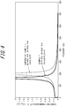
- FIG. 4 and FIG. 5 illustrate simulation results in Examples 1 and 2 and Comparative Examples 1 and 2 of the active anti-vibration device of the present disclosure.
- Examples 1 and 2 and Comparative Examples 1 and 2 each have a configuration of the active anti-vibration device 10 in the example of FIG. 1 to FIG. 3 .
- Examples 1 and 2 and Comparative Examples 1 and 2 are identical in various configurations such as the dimensions and the mass, and are only different in the control method using the actuator 50.
- the acceleration feedback control is abbreviated as "AFB” and the velocity feedback control is abbreviated as "VFB” for the sake of simplicity.
- the first force Fa1 represented by the above-described equation (1) was used as the first force Fa1 in the acceleration feedback control
- the second force Fa2 represented by the above-described equation (6) was used as the second force Fa2 in the velocity feedback control.
- the details of the gains Ga and Gv are presented in FIG. 4 and FIG. 5 .
- the horizontal axis represents a frequency (Hz)
- the vertical axis represents a vibration transmissibility Tr.
- x 1 denotes an axial displacement of the inner cylinder 22 of the first elastic connecting part 20
- x 2 denotes an axial displacement of the rod body 40.
- Example 1 the resonance frequency in Example 1 in which only the acceleration feedback control was performed is smaller than that in Comparative Example 1 in which both of the acceleration feedback control and the velocity feedback control were not performed. That is, in Example 1, an effect equivalent to that in the case where the mass of the rod body 40 is increased can be obtained, as compared with Comparative Example 1.
- the vibration transmissibility Tr (peak value) at the resonance frequency in Example 2 and Comparative Example 2 in which the velocity feedback control was performed is smaller than that in Example 1 and Comparative Example 1 ( FIG. 4 ) in which no velocity feedback control was performed. Furthermore, the vibration transmissibility in a band of not lower than 170 Hz in Example 2 in which both of the acceleration feedback control and the velocity feedback control were performed is lower than that in Comparative Example 2 in which only the velocity feedback control was performed. In Example 2, an effect equivalent to that in the case where the mass of the rod body 40 is increased can be obtained, as compared with Comparative Example 2.
- FIG. 6 and FIG. 7 illustrate experimental results in Examples 3 to 10 and Comparative Examples 3 to 5 of the active anti-vibration device of the present disclosure.
- Examples 3 to 10 and Comparative Examples 3 to 5 each have a configuration of the active anti-vibration device 10 in the example of FIG. 1 to FIG. 3 .
- Examples 3 to 10 and Comparative Examples 3 to 5 are identical in various configurations such as the dimensions and the mass, and are only different in the control method using the actuator 50.
- the acceleration feedback control is abbreviated as "AFB” and the velocity feedback control is abbreviated as "VFB” for the sake of simplicity.
- the first force Fa1 represented by the above-described equation (1) was used as the first force Fa1 in the acceleration feedback control
- the second force Fa2 represented by the above-described equation (6) was used as the second force Fa2 in the velocity feedback control.
- the details of the gains Ga and Gv are presented in FIG. 6 and FIG. 7 . Note that numerical values of the gains Ga and Gv presented in FIG. 6 and FIG. 7 are obtained by converting actual values into relative representative values.
- the horizontal axis represents a frequency (Hz)
- the vertical axis represents a vibration transmissibility.
- the value of the vibration transmissibility on the vertical axis becomes larger toward the upside of the figure.
- the resonance frequency in Examples 3 to 7 in which only the acceleration feedback control was performed is smaller than that in Comparative Example 3 in which both of the acceleration feedback control and the velocity feedback control were not performed. Furthermore, the vibration transmissibility (peak value) at the resonance frequency in Examples 3 to 7 in which the acceleration feedback control was performed is smaller than that in Comparative Example 3 in which acceleration feedback control was not performed.
- the resonance frequency in Examples 8 to 10 in which both of the acceleration feedback control and the velocity feedback control were performed is smaller than that in Comparative Examples 3 to 5 in which acceleration feedback control was not performed.
- Comparison among Examples 8 to 10 reveals that the larger velocity feedback gain Gv indicates a lower vibration transmissibility (peak value) at the resonance frequency.
- Comparison between Comparative Example 4 and Comparative Example 9 reveals that the velocity feedback gain Gv in Example 9 in which the acceleration feedback control was performed is slightly smaller than that in Comparative Example 4 in which the acceleration feedback control was not performed, but the vibration transmissibility at the resonance frequency in Example 9 is lower than that in Comparative Example 4.
- active anti-vibration device 10 and a method of controlling the same according to the present disclosure are not limited to the above-described examples, and various variant examples are possible.
- the controller 90 may perform the acceleration feedback control so that the vibration frequency of the engine connected to the active anti-vibration device 10 is away from the rod resonance frequency of the active anti-vibration device 10 by equal to or more than a predetermined frequency.
- the controller 90 preferably uses, for example, an engine speed signal from a vehicle, as an engine vibration frequency.
- the value of the acceleration feedback gain Ga is changed (for example, the sign is reversed) to change the rod resonance frequency, so that the vibration frequency of the engine is away from the rod resonance frequency by equal to or more than a predetermined frequency. This enables the vibration performance to be improved while reducing power consumption.
- the active anti-vibration device and the method of controlling the same according to the present disclosure can be used for a torque rod configured to connect an engine side and a vehicle body side of a vehicle, for example.
Landscapes
- Engineering & Computer Science (AREA)
- General Engineering & Computer Science (AREA)
- Mechanical Engineering (AREA)
- Chemical & Material Sciences (AREA)
- Combustion & Propulsion (AREA)
- Transportation (AREA)
- Physics & Mathematics (AREA)
- Acoustics & Sound (AREA)
- Aviation & Aerospace Engineering (AREA)
- Electromagnetism (AREA)
- Vibration Prevention Devices (AREA)
- Arrangement Or Mounting Of Propulsion Units For Vehicles (AREA)
Abstract
Description
- The present disclosure relates to an anti-vibration device and a method of controlling the active-vibration device.
- The present application claims priority based on Japanese Patent Application No.
2017-102164, filed May 23, 2017 - As a conventional active anti-vibration device, there is a device that performs velocity feedback control that controls a drive part so that a force proportional to an axial velocity of a rod body is generated (for example, see PTL 1).
- PTL 1: Japanese Patent Laid-Open No.
2016-75380 - In the above-described conventional active anti-vibration device, the anti-vibration performance and the resonance frequency are mainly determined by a mass of a rod body.
- When the resonance frequency is high, the anti-vibration frequency region on the higher side than the resonance frequency becomes narrow. Therefore, it is necessary to increase the mass of the rod body to reduce the resonance frequency to enlarge the anti-vibration frequency region on the higher side than the resonance frequency. However, this may cause the fuel efficiency of the vehicle to be deteriorated by an amount equivalent to increase in the mass of the rod body. Accordingly, it can be said that an anti-vibration performance equivalent to that in the case where the mass of the rod body is increased is preferably obtained without actually increasing the mass of the rod body.
- Thus, there is desired a technique of achieving the anti-vibration performance equivalent to that in the case where the mass of the rod body differs from the actual mass.
- The present disclosure has been made to solve the above-described problems, and an object of the present disclosure is to provide an active anti-vibration device capable of achieving an anti-vibration performance equivalent to that in a case where a mass of a rod body differs from an actual mass, and a method of controlling the active anti-vibration device.
- An active anti-vibration device of the present disclosure includes a pair of elastic connecting parts, a rod body that connects the pair of elastic connecting parts, an inertial mass that is supported by the rod body, a drive part that reciprocates the inertial mass in an axial direction of the rod body, and a controller that is configured to be able to perform acceleration feedback control to control the drive part so that a first force proportional to an axial acceleration of the rod body is generated.
- In a method of controlling an active anti-vibration device of the present disclosure, the active anti-vibration device comprising a pair of elastic connecting parts, a rod body that connects the pair of elastic connecting parts, an inertial mass that is supported by the rod body, a drive part that reciprocates the inertial mass in an axial direction of the rod body, and a controller that controls the drive part, the controller performs acceleration feedback control by controlling the drive part so that a first force proportional to an axial acceleration of the rod body is generated.
- According to the present disclosure, there can be provided an active anti-vibration device capable of achieving an anti-vibration performance equivalent to that in a case where a mass of a rod body differs from an actual mass, and a method of controlling the active anti-vibration device.
- In the accompanying drawings:
-
FIG. 1 is a cross sectional view illustrating an active anti-vibration device according to one embodiment of the present disclosure; -
FIG. 2 is a main portion cross-sectional view enlarging and illustrating a main portion of the active anti-vibration device ofFIG. 1 in an operation state; -
FIG. 3 is a diagram schematically illustrating a physical model of the active anti-vibration device ofFIG. 1 ; -
FIG. 4 is a graph presenting simulation results of Example 1 and Comparative Example 1 of an active anti-vibration device of the present disclosure; -
FIG. 5 is a graph presenting simulation results of Example 2 and Comparative Example 2 of the active anti-vibration device of the present disclosure; -
FIG. 6 is a graph presenting experimental results of Examples 3 to 7 and Comparative Example 3 of the active anti-vibration device of the present disclosure; and -
FIG. 7 is a graph presenting experimental results of Examples 8 to 10 and Comparative Examples 3 to 5 of the active anti-vibration device of the present disclosure. - The following illustrates and describes an embodiment of an active anti-vibration device according to the present disclosure and a method of controlling the active anti-vibration device with reference to the drawings.
- Firstly, an overall configuration of an active
anti-vibration device 10 according to one embodiment of the present disclosure will be described with reference toFIG. 1 to FIG. 3 . -
FIG. 1 is a cross-sectional view illustrating an activeanti-vibration device 10 according to the present embodiment.FIG. 2 is a main portion cross-sectional view enlarging and illustrating a main portion of the active anti-vibration device ofFIG. 1 in an operation state. The activeanti-vibration device 10 of the present embodiment is structured as a torque rod, and is configured to connect an engine side and a vehicle body side of a vehicle. More specifically, the activeanti-vibration device 10 in the illustrated example is suitable for use as an upper torque rod to be connected to the engine mounted to the vehicle body by means of a pendulum mount structure. Note that the active anti-vibration device of the present disclosure may be configured to be connected to the engine by means of a supporting structure other than the pendulum mount structure, or may be configured to be used as a torque rod other than the upper torque rod. - The active
anti-vibration device 10 of the present embodiment includes a pair of elastic connectingparts rod body 40 connecting the pair of elastic connectingparts actuator 50 disposed in therod body 40, anaccelerometer 80 attached to therod body 40, acontroller 90, and anamplifier 100. - The
rod body 40 integrally includes a firstouter cylinder part 41 that accommodates the first elastic connectingpart 20 of the pair of elastic connectingparts outer cylinder part 41, a secondouter cylinder part 42 that accommodates the second elastic connectingpart 30 at an inner circumferential side of the secondouter cylinder part 42, and amiddle part 43 that extends straight between the firstouter cylinder part 41 and the secondouter cylinder part 42. - In this specification, an extending direction of a central axis C of the
rod body 40 is referred to as an axial direction of the rod body 40 (also simply referred to as an "axial direction"). - The
rod body 40 is made of, for example, metal such as iron or aluminum, or resin. - The first elastic connecting
part 20 and the second elastic connectingpart 30 include respectiveinner cylinders outer cylinder part 41 and the secondouter cylinder part 42, respectively, and respectiveelastic members 23 and 33 that connect inner circumferential surfaces of the firstouter cylinder part 41 and the secondouter cylinder part 42 and outer circumferential surfaces ofinner cylinders elastic members 23 and 33 are made of, for example, rubber. - In the example illustrated in
FIG. 1 , the first elastic connectingpart 20 has an outer diameter larger than the second elastic connectingpart 30. - In this example, the first elastic connecting
part 20 is configured to be connected to the engine side of the vehicle, and the second elastic connectingpart 30 is configured to be connected to the vehicle body side of the vehicle. - In the example illustrated in
FIG. 1 , the central axis of theinner cylinder 22 of the first elastic connectingpart 20 and the central axis of theinner cylinder 32 of the second elastic connectingpart 30 extend in mutually perpendicular directions, but the directional relation between these central axes is not limited thereto, and, for example, both may extend in parallel to each other. - The
actuator 50 is disposed in arecess 44 formed in therod body 40. Theactuator 50 is formed as a linear movable actuator, and includes ashaft 51, aninertial mass 52, a connectingmember 53, apermanent magnet 54, acoil 55, and awinding core 56. Among these, thepermanent magnet 54, thecoil 55 and thewinding core 56 form adrive part 58 configured to drive theinertial mass 52 in the axial direction. - The
shaft 51 extends in the axial direction ofrod body 40 in therecess 44 of therod body 40. Both ends of theshaft 51 in the axial direction are fixed to a pair of inner wall surfaces facing each other in the axial direction among the inner wall surfaces defining therecess 44 of therod body 40. In the example illustrated inFIG. 1 , the central axis of theshaft 51 coincides with the central axis of therod body 40. Note that only one end of theshaft 51 in the axial direction may be fixed to the inner wall surface of therecess 44 of therod body 40. - The
inertial mass 52 is formed into a cylindrical shape coaxially with theshaft 51, and is connected to theshaft 51 through the connectingmember 53 extending in a radial direction, to thereby be supported by therod body 40. In the example illustrated inFIG. 1 , ends of theinertial mass 52 on both sides in the axial direction are connected to theshaft 51 through the respective connectingmembers 53, but only the end of theinertial mass 52 on one side in the axial direction may be connected to theshaft 51 through the connectingmember 53. - The connecting
member 53 is comprised of an elastic member such as a plate spring. - A pair of
permanent magnets 54 adjacent to each other in the axial direction are fixed on the inner circumferential surface of theinertial mass 52 in a state in which thepermanent magnets 54 are reverse-polarized to each other. - The winding
core 56 and thecoil 55 wound around the windingcore 56 are fixed to the outer circumferential surface of theshaft 51 to be spaced inward in the radial direction from thepermanent magnets 54. One end of alead wire 57 extending outside of the activeanti-vibration device 10 is connected to thecoil 55. The other end of thelead wire 57 is connected to theamplifier 100. - Although not illustrated in
FIG. 1 , thepermanent magnets 54 may be fixed to the outer circumferential surface of the windingcore 56. - In the
actuator 50 configured as described above, when the voltage is applied to thecoil 55 through thelead wire 57 from theamplifier 100, thewinding core 56 and thecoil 55 function as an electromagnet. As exaggerated in the enlarged cross-sectional view ofFIG. 2 , theinertial mass 52 is relatively displaced to either one side in the axial direction with respect to theshaft 51 based on a repulsive force generated between the same poles or an attractive force generated between the opposite poles, the repulsive force or the attractive force acting between thewinding core 56 and thepermanent magnet 54. In the example inFIG. 2 , theinertial mass 52 is relatively displaced to the first elastic connectingpart 20 side (an upper side ofFIG. 2 ) with respect to theshaft 51. Then, a force Fa indicated by an arrow inFIG. 2 is generated in the activeanti-vibration device 10 based on a restoring force of the elastic deformation of the connectingmember 53 connecting theinertial mass 52 and theshaft 51. On the other hand, a force in a direction opposite to the force Fa indicated by an arrow inFIG. 2 is generated in theinertial mass 52, so that theinertial mass 52 returns to an original arrangement position illustrated inFIG. 1 . - The direction of the current flowing through the
coil 55 is reversed to relatively displace theinertial mass 52 to the other side in the axial direction with respect to theshaft 51. - The
accelerometer 80 detects and outputs an axial acceleration of therod body 40. In the example illustrated inFIG. 1 , theaccelerometer 80 is attached to an outer surface of therod body 40, but may be attached to any position of therod body 40. The acceleration detected by theaccelerometer 80 is output to thecontroller 90 via wired communication or via wireless communication, as needed. - The
controller 90 is configured to allow the axial force Fa to be generated in therod body 40 while controlling thedrive part 58 of theactuator 50 based on an axial acceleration of therod body 40, the acceleration being detected by theaccelerometer 80. As described later, thecontroller 90 is configured to be able to perform at least acceleration feedback control. A signal output from thecontroller 90 is input to theamplifier 100. - The
controller 90 is comprised of a computer having an arithmetic unit such as a CPU and a storage unit such as a ROM and a RAM, for example, and operates according to a program pre-stored in a storage device. - The
amplifier 100 amplifies a signal input from thecontroller 90, and applies the amplified signal to thecoil 55 of theactuator 50 to control the voltage. Theamplifier 100 is comprised of, for example, an operational amplifier. - In the active
anti-vibration device 10 configured as described above, the vibration input from the engine side is attenuated mainly by the vibration of therod body 40 serving as a mass. - On the other hand, generally stated, the
actuator 50 serves to reinforce a drawback of therod body 40 by the electric control. More specifically, theactuator 50 is configured to be able to improve the anti-vibration performance by actively controlling a value of a rod resonance frequency (hereinafter also simply referred to as a "resonance frequency") of the activeanti-vibration device 10 and a vibration transmissibility near the resonance frequency. - Note that the rod resonance frequency of the active
anti-vibration device 10 is mainly determined by the mass of therod body 40 and the characteristics of theelastic members 23 and 33 while noactuator 50 is operating. -
FIG. 3 schematically illustrates a physical model of the activeanti-vibration device 10 ofFIG. 1 . InFIG. 3 , reference signs "ki" and "k2" represent spring constants of the elastic member 23 and theelastic member 33, respectively, reference sign "Mr" represents a mass of therod body 40, reference sign "Ma" represents a mass of theinertial mass 52 of theactuator 50, and reference sign "ka" represents a spring constant of the connectingmember 53. Reference sign "A" represents thedrive part 58. Reference sign "Fe" represents a force to be input to the activeanti-vibration device 10 from the engine side, reference sign "Fb" represents a force to be input to the vehicle body side from the activeanti-vibration device 10, and reference sign "Fa" represents a force generated by theactuator 50. Reference sign "x1" represents an axial displacement of theinner cylinder 22 of the first elastic connectingpart 20, reference sign "x2" represents an axial displacement of therod body 40, and reference sign "x3" represents an axial displacement of theinertial mass 52. - Note that in the example illustrated in
FIG. 1 , theaccelerometer 80 detects the acceleration corresponding to a value obtained by differentiating x2 ofFIG. 3 twice. - Next, a method of controlling the active
anti-vibration device 10 of the present embodiment described above will be described. - The
controller 90 of the activeanti-vibration device 10 of the present embodiment is configured to be able to perform at least the acceleration feedback control. - The
controller 90 may always perform the acceleration feedback control or may perform the acceleration feedback control at an arbitrary timing such as only while satisfying a predetermined condition, for example. - The
controller 90 may be configured to be able to further perform velocity feedback control in addition to the acceleration feedback control. Thecontroller 90 may always perform the velocity feedback control or may perform the velocity feedback control at an arbitrary timing such as only while satisfying a predetermined condition, for example. - It is preferable that the
controller 90 performs the acceleration feedback control and the velocity feedback control at the same time. - Hereinafter, the acceleration feedback control and the velocity feedback control will be described in turn. Note that in the following description, reference signs that differ from those illustrated in the physical model of
FIG. 3 are used for the sake of simplicity. - In the acceleration feedback control, the
controller 90 controls thedrive part 58 so that a first force Fa1 proportional to the axial acceleration of therod body 40 is generated in therod body 40. - The first force Fa1 can be represented by the following equation (1), for example.
[Expression 1]
- In the equation (1), "Ga" represents an acceleration feedback gain (positive number), and "d2x/dt2" (twice differential for x) represents an axial acceleration of the
rod body 40. - A direction of the first force Fa1 represented by the equation (1) is opposite to the direction of the axial acceleration d2x/dt2 of the
rod body 40. - In the present example, the
controller 90 uses the acceleration output from theaccelerometer 80 as a value of d2x/dt2. Note that the axial acceleration d2x/dt2 of therod body 40 may be obtained by the other method. - The
controller 90 determines a value of the acceleration feedback gain Ga. The acceleration feedback gain Ga may be constant during the acceleration feedback control or may be changed when a predetermined condition is satisfied, for example. - The
amplifier 100 increases the voltage according to the determined acceleration feedback gain Ga, and applies the voltage to thecoil 55 of thedrive part 58 so that the first force Fa1 is generated. - Here, the effect of the acceleration feedback control will be described.
- Firstly, a motion equation of the active
anti-vibration device 10 is schematically defined by the following equation (2).
[Expression 2]
- In the equation (2), reference sign "m" represents a mass (mainly including the mass of the rod body), reference sign "c" represents an attenuation coefficient, reference sign "k" represents a spring constant (a combined spring constant of k1 and k2), reference sign "x" represents an axial displacement of the
rod body 40, reference sign "Fe" represents a force to be input from the engine side to the activeanti-vibration device 10, and reference sign "Fa1" represents a first force generated by theactuator 50. - By substituting the equation (1) into the equation (2), the following equation is obtained.
[Expression 3]
- In this way, in the acceleration feedback control of this example, as represented by the equation (1), the first force Fa1 proportional to the axial acceleration d2x/dt2 of the
rod body 40 is generated in the direction opposite to the direction of the axial acceleration d2x/dt2 of therod body 40. Accordingly, a coefficient of an acceleration term in the motion equation represented by the equation (3) is increased from m to m+Ga. This means that the activeanti-vibration device 10 can be operated as if the mass of therod body 40 was larger than the actual mass (that is, as if the mass of therod body 40 was virtually increased). Therefore, an effect (anti-vibration performance) equivalent to that in the case where the mass of therod body 40 is increased relative to the actual mass can be obtained. When the virtual mass of therod body 40 is thus operated, the rod resonance frequency can be operated (can be reduced in the present example). - Here, in a conventional typical torque rod, the rod body is made of relatively light-weight material such as aluminum or resin, and the resonance frequency is about 600 to 800 Hz. However, since the needs for attenuation of the vibration are increased at a lower frequency, in the recent active anti-vibration device, the rod body is made of a heavy material such as a casting made of iron in some cases, so that the resonance frequency is as low as about 200 Hz, the anti-vibration frequency region having a frequency of √2 (the square root of 2) times or more higher than the resonance frequency is enlarged, and the vibration transmissibility near the resonance frequency is reduced by the velocity feedback control. However, this may cause the fuel efficiency to be deteriorated by an amount equivalent to increase in the mass of the rod body.
- Meanwhile, according to the acceleration feedback control of this example, the resonance frequency can be reduced without actually increasing the mass of the
rod body 40, and the anti-vibration frequency region on the higher side than the resonance frequency, more specifically, the anti-vibration frequency region having a frequency of √2 (the square root of 2) times or more higher than the resonance frequency can be enlarged. Since the mass of therod body 40 need not be increased, the deterioration in fuel efficiency can be suppressed. - According to the acceleration feedback control of this example, the mass of the
rod body 40 can be also reduced without changing the resonance frequency. This enables the fuel efficiency to be improved while maintaining the anti-vibration performance. - According to the acceleration feedback control of this example, the vibration transmissibility near the resonance frequency can be reduced without performing the velocity feedback control.
- Note that, in the acceleration feedback control, a first force Fa1 represented by the following equation (4) instead of the equation (1) may be used as the first force Fa1.
[Expression 4]
- A direction of the first force Fa1 represented by the equation (4) is the same as the direction of the axial acceleration d2x/dt2 of the
rod body 40. - By substituting the equation (4) into the equation (2), the following equation is obtained.
[Expression 5]
- In this way, in the acceleration feedback control of this example, as represented by the equation (4), the first force Fa1 proportional to the axial acceleration d2x/dt2 of the
rod body 40 is generated in the direction the same as the direction of the axial acceleration d2x/dt2 of therod body 40. Accordingly, a coefficient of an acceleration term in the motion equation represented by the equation (5) is reduced from m to m-Ga. This means that the activeanti-vibration device 10 can be operated as if the mass of therod body 40 was smaller than the actual mass (that is, as if the mass of therod body 40 was virtually reduced). Therefore, an effect (anti-vibration performance) equivalent to that in the case where the mass of therod body 40 is reduced relative to the actual mass can be obtained. This enables the resonance frequency to be increased without actually reducing the mass of therod body 40. - As described above, according to the present embodiment, by performing the acceleration feedback control, the anti-vibration performance equivalent to that in the case where the mass of the rod body differs from the actual mass can be achieved. By thus operating the virtual mass of the
rod body 40, the resonance frequency can be operated. - As described above, the
controller 90 may be configured to be able to perform the velocity feedback control in addition to the acceleration feedback control. - In the velocity feedback control, the
controller 90 controls thedrive part 58 so that a second force Fa2 proportional to an axial velocity of therod body 40 is generated in therod body 40. - The second force Fa2 can be represented by the following equation (6), for example.
[Expression 6]
- In the equation (6), reference sign "Gv" represents a velocity feedback gain (positive number), and reference sign "dx/dt" (once differential for x) represents an axial velocity of the
rod body 40. - A direction of the second force Fa2 represented by the equation (6) is opposite to the direction of the axial velocity dx/dt of the
rod body 40. - In the present example, the
controller 90 uses, as a value of dx/dt, the velocity obtained by integrating the acceleration output from theaccelerometer 80 once. Accordingly, one sensor (accelerometer) can be used for both of the acceleration feedback control and the velocity feedback control, whereby an increase in size and an increase in cost can be suppressed. Note that the axial velocity dx/dt of therod body 40 may be obtained by the other method. - The
controller 90 determines a value of the velocity feedback gain Gv. The velocity feedback gain Gv may be constant during the velocity feedback control or may be changed when a predetermined condition is satisfied, for example. - The
amplifier 100 increases the voltage according to the velocity feedback gain Gv determined by thecontroller 90, and applies the voltage to thecoil 55 of thedrive part 58 so that the second force Fa2 is generated. - Note that, when the acceleration feedback control and the velocity feedback control are performed at the same time, the
amplifier 100 controls the voltage of thedrive part 58 so that a force obtained by adding the first force Fa1 and the second force Fa2 is generated in therod body 40. - Here, the effect when the velocity feedback control is performed in addition to the acceleration feedback control will be described.
- Firstly, a motion equation of the active
anti-vibration device 10 is schematically defined by the following equation (7).
[Expression 7]
- In the equation (7), reference sign "m" represents a mass (mainly including the mass of the rod body), reference sign "c" represents an attenuation coefficient, reference sign "k" represents a spring constant (a combined spring constant of kl and k2), reference sign "x" represents an axial displacement of the
rod body 40, reference sign "Fe" represents a force to be input from the engine side to the activeanti-vibration device 10, and reference signs "Fa1" and "Fa2" represent a first force and a second force generated by theactuator 50, respectively. - By substituting the equation (1) and the equation (6) into the equation (7), the following equation is obtained.
[Expression 8]
- In this way, in the velocity feedback control of this example, as represented by the equation (6), the second force Fa2 proportional to the axial velocity dx/dt of the
rod body 40 is generated in the direction opposite to the direction of the axial velocity dx/dt of therod body 40. Accordingly, a coefficient of a velocity term (attenuation term) in the motion equation represented by the equation (8) is increased from c to c+Gv. This enables a reduction in the vibration transmissibility, in particular, a significant reduction of high vibration transmissibility near the resonance frequency. - Also in this example, the above-described effect of the acceleration feedback control can be obtained using the equations (1) to (3). Note that a first force Fa1 represented by the following equation (4) may be used as the first force Fa1.
- Here, examples and comparative examples of an active anti-vibration device of the present disclosure will be described with reference to
FIG. 4 to FIG. 7 . -
FIG. 4 andFIG. 5 illustrate simulation results in Examples 1 and 2 and Comparative Examples 1 and 2 of the active anti-vibration device of the present disclosure. - Examples 1 and 2 and Comparative Examples 1 and 2 each have a configuration of the active
anti-vibration device 10 in the example ofFIG. 1 to FIG. 3 . Examples 1 and 2 and Comparative Examples 1 and 2 are identical in various configurations such as the dimensions and the mass, and are only different in the control method using theactuator 50. InFIG. 4 andFIG. 5 , the acceleration feedback control is abbreviated as "AFB" and the velocity feedback control is abbreviated as "VFB" for the sake of simplicity. The first force Fa1 represented by the above-described equation (1) was used as the first force Fa1 in the acceleration feedback control, and the second force Fa2 represented by the above-described equation (6) was used as the second force Fa2 in the velocity feedback control. The details of the gains Ga and Gv are presented inFIG. 4 andFIG. 5 . - In
FIG. 4 andFIG. 5 , the horizontal axis represents a frequency (Hz), and the vertical axis represents a vibration transmissibility Tr. The vibration transmissibility Tr is represented by Tr = |x2/x1|. As illustrated inFIG. 3 , x1 denotes an axial displacement of theinner cylinder 22 of the first elastic connectingpart 20, and x2 denotes an axial displacement of therod body 40. - In
FIG. 4 , the resonance frequency in Example 1 in which only the acceleration feedback control was performed is smaller than that in Comparative Example 1 in which both of the acceleration feedback control and the velocity feedback control were not performed. That is, in Example 1, an effect equivalent to that in the case where the mass of therod body 40 is increased can be obtained, as compared with Comparative Example 1. - In
FIG. 5 , the vibration transmissibility Tr (peak value) at the resonance frequency in Example 2 and Comparative Example 2 in which the velocity feedback control was performed is smaller than that in Example 1 and Comparative Example 1 (FIG. 4 ) in which no velocity feedback control was performed. Furthermore, the vibration transmissibility in a band of not lower than 170 Hz in Example 2 in which both of the acceleration feedback control and the velocity feedback control were performed is lower than that in Comparative Example 2 in which only the velocity feedback control was performed. In Example 2, an effect equivalent to that in the case where the mass of therod body 40 is increased can be obtained, as compared with Comparative Example 2. -
FIG. 6 andFIG. 7 illustrate experimental results in Examples 3 to 10 and Comparative Examples 3 to 5 of the active anti-vibration device of the present disclosure. - Examples 3 to 10 and Comparative Examples 3 to 5 each have a configuration of the active
anti-vibration device 10 in the example ofFIG. 1 to FIG. 3 . Examples 3 to 10 and Comparative Examples 3 to 5 are identical in various configurations such as the dimensions and the mass, and are only different in the control method using theactuator 50. InFIG. 6 andFIG. 7 , the acceleration feedback control is abbreviated as "AFB" and the velocity feedback control is abbreviated as "VFB" for the sake of simplicity. The first force Fa1 represented by the above-described equation (1) was used as the first force Fa1 in the acceleration feedback control, and the second force Fa2 represented by the above-described equation (6) was used as the second force Fa2 in the velocity feedback control. The details of the gains Ga and Gv are presented inFIG. 6 andFIG. 7 . Note that numerical values of the gains Ga and Gv presented inFIG. 6 andFIG. 7 are obtained by converting actual values into relative representative values. - In
FIG. 6 andFIG. 7 , the horizontal axis represents a frequency (Hz), and the vertical axis represents a vibration transmissibility. The value of the vibration transmissibility on the vertical axis becomes larger toward the upside of the figure. - In
FIG. 6 , the resonance frequency in Examples 3 to 7 in which only the acceleration feedback control was performed is smaller than that in Comparative Example 3 in which both of the acceleration feedback control and the velocity feedback control were not performed. Furthermore, the vibration transmissibility (peak value) at the resonance frequency in Examples 3 to 7 in which the acceleration feedback control was performed is smaller than that in Comparative Example 3 in which acceleration feedback control was not performed. - In
FIG. 6 , comparison among Examples 3 to 7 in which only the acceleration feedback control was performed reveals that a larger acceleration feedback gain Ga indicates a lower resonance frequency. Comparison among Examples 3 to 7 reveals that a larger acceleration feedback gain Ga indicates a lower vibration transmissibility (peak value) at the resonance frequency. - In
FIG. 7 , comparison among Comparative Examples 3 to 5 reveals that the resonance frequency is almost the same, but the larger velocity feedback gain Gv indicates a lower vibration transmissibility (peak value) at the resonance frequency. - In
FIG. 7 , the resonance frequency in Examples 8 to 10 in which both of the acceleration feedback control and the velocity feedback control were performed is smaller than that in Comparative Examples 3 to 5 in which acceleration feedback control was not performed. Comparison among Examples 8 to 10 reveals that the larger velocity feedback gain Gv indicates a lower vibration transmissibility (peak value) at the resonance frequency. Comparison between Comparative Example 4 and Comparative Example 9 reveals that the velocity feedback gain Gv in Example 9 in which the acceleration feedback control was performed is slightly smaller than that in Comparative Example 4 in which the acceleration feedback control was not performed, but the vibration transmissibility at the resonance frequency in Example 9 is lower than that in Comparative Example 4. - Note that the active
anti-vibration device 10 and a method of controlling the same according to the present disclosure are not limited to the above-described examples, and various variant examples are possible. - For example, the
controller 90 may perform the acceleration feedback control so that the vibration frequency of the engine connected to the activeanti-vibration device 10 is away from the rod resonance frequency of the activeanti-vibration device 10 by equal to or more than a predetermined frequency. In this case, thecontroller 90 preferably uses, for example, an engine speed signal from a vehicle, as an engine vibration frequency. - More specifically, the value of the acceleration feedback gain Ga is changed (for example, the sign is reversed) to change the rod resonance frequency, so that the vibration frequency of the engine is away from the rod resonance frequency by equal to or more than a predetermined frequency. This enables the vibration performance to be improved while reducing power consumption.
- The active anti-vibration device and the method of controlling the same according to the present disclosure can be used for a torque rod configured to connect an engine side and a vehicle body side of a vehicle, for example.
-
- 10
- Active anti-vibration device
- 20
- First elastic connecting part (elastic connecting part)
- 22
- Inner cylinder
- 23
- Elastic member
- 30
- Second elastic connecting part (elastic connecting part)
- 32
- Inner cylinder
- 33
- Elastic member
- 40
- Rod body
- 41
- First outer cylinder part
- 42
- Second outer cylinder part
- 43
- Middle part
- 44
- Recess
- 50
- Actuator
- 51
- Shaft
- 52
- Inertial mass
- 53
- Connecting member
- 54
- Permanent magnet
- 55
- Coil
- 56
- Winding core
- 57
- Lead wire
- 58
- Drive part
- 80
- Accelerometer
- 90
- Controller
- 100
- Amplifier
- C
- Central axis of rod body
Claims (10)
- An active anti-vibration device, comprising:a pair of elastic connecting parts;a rod body that connects the pair of elastic connecting parts;an inertial mass that is supported by the rod body;a drive part that reciprocates the inertial mass in an axial direction of the rod body; anda controller that is configured to be able to perform acceleration feedback control to control the drive part so that a first force proportional to an axial acceleration of the rod body is generated.
- The active anti-vibration device according to claim 1, wherein in the acceleration feedback control, the controller generates the first force in a direction opposite to a direction of the axial acceleration of the rod body.
- The active anti-vibration device according to claim 1 or 2, wherein
the controller is configured to be able to further perform velocity feedback control to control the drive part so that a second force proportional to an axial velocity of the rod body is generated. - The active anti-vibration device according to claim 3, further comprising:an accelerometer that is attached to the rod body and detects the axial acceleration of the rod body,wherein the controllerin the acceleration feedback control, uses the acceleration detected by the accelerometer, andin the velocity feedback control, uses a velocity obtained by integrating the acceleration detected by the accelerometer.
- The active anti-vibration device according to any one of claims 1 to 4, wherein
one of the pair of elastic connecting parts is configured to be connected to an engine side of a vehicle,
the other of the pair of elastic connecting parts is configured to be connected to a vehicle body side of the vehicle, and
the controller performs the acceleration feedback control so that a vibration frequency of the engine is away from a rod resonance frequency of the active anti-vibration device by equal to or more than a predetermined frequency. - A method of controlling an active anti-vibration device, the active anti-vibration device comprising:a pair of elastic connecting parts;a rod body that connects the pair of elastic connecting parts;an inertial mass that is supported by the rod body;a drive part that reciprocates the inertial mass in an axial direction of the rod body; anda controller that controls the drive part,wherein the controller performs acceleration feedback control by controlling the drive part so that a first force proportional to an axial acceleration of the rod body is generated.
- The method of controlling an active anti-vibration device according to claim 6, wherein
in the acceleration feedback control, the controller generates the first force in a direction opposite to a direction of the axial acceleration of the rod body. - The method of controlling an active anti-vibration device according to claim 6 or 7, wherein
the controller further performs velocity feedback control to control the drive part so that a second force proportional to an axial velocity of the rod body is generated. - The method of controlling an active anti-vibration device according to claim 8, the active anti-vibration device further comprising: an accelerometer that is attached to the rod body and detects the axial acceleration of the rod body,
wherein the controller
in the acceleration feedback control, uses the acceleration detected by the accelerometer, and
in the velocity feedback control, uses a velocity obtained by integrating the acceleration detected by the accelerometer. - The method of controlling an active anti-vibration device according to any one of claims 6 to 9, wherein
in the active anti-vibration device,
one of the pair of elastic connecting parts is configured to be connected to an engine side of a vehicle,
the other of the pair of elastic connecting parts is configured to be connected to a vehicle body side of the vehicle, and
the controller performs the acceleration feedback control so that a vibration frequency of the engine is away from a rod resonance frequency of the active anti-vibration device by equal to or more than a predetermined frequency.
Applications Claiming Priority (2)
| Application Number | Priority Date | Filing Date | Title |
|---|---|---|---|
| JP2017102164A JP6887311B2 (en) | 2017-05-23 | 2017-05-23 | Active anti-vibration device and control method of active anti-vibration device |
| PCT/JP2018/004833 WO2018216268A1 (en) | 2017-05-23 | 2018-02-13 | Active-type vibration-damping device and method for controlling active-type vibration-damping device |
Publications (3)
| Publication Number | Publication Date |
|---|---|
| EP3633230A1 true EP3633230A1 (en) | 2020-04-08 |
| EP3633230A4 EP3633230A4 (en) | 2021-03-10 |
| EP3633230B1 EP3633230B1 (en) | 2023-08-16 |
Family
ID=64395471
Family Applications (1)
| Application Number | Title | Priority Date | Filing Date |
|---|---|---|---|
| EP18806340.8A Active EP3633230B1 (en) | 2017-05-23 | 2018-02-13 | Active anti-vibration device and method of controlling an active anti-vibration device |
Country Status (5)
| Country | Link |
|---|---|
| US (1) | US11292329B2 (en) |
| EP (1) | EP3633230B1 (en) |
| JP (1) | JP6887311B2 (en) |
| CN (1) | CN110662907B (en) |
| WO (1) | WO2018216268A1 (en) |
Families Citing this family (4)
| Publication number | Priority date | Publication date | Assignee | Title |
|---|---|---|---|---|
| US11491832B2 (en) * | 2018-02-27 | 2022-11-08 | Methode Electronics, Inc. | Towing systems and methods using magnetic field sensing |
| JP7526472B2 (en) * | 2020-09-23 | 2024-08-01 | 山下ゴム株式会社 | Torque rod |
| CN113653763A (en) * | 2021-07-09 | 2021-11-16 | 广西科技大学 | Vibration damper of reciprocating mechanism |
| US12624741B1 (en) * | 2025-05-07 | 2026-05-12 | Steadiwear Inc. | Vibration absorber |
Family Cites Families (14)
| Publication number | Priority date | Publication date | Assignee | Title |
|---|---|---|---|---|
| US4610420A (en) * | 1984-02-16 | 1986-09-09 | Nissan Motor Company, Limited | Apparatus for mounting power unit |
| JPH05286332A (en) * | 1992-04-15 | 1993-11-02 | Mazda Motor Corp | Vehicle vibration reduction device |
| JP5136408B2 (en) * | 2006-05-08 | 2013-02-06 | シンフォニアテクノロジー株式会社 | Vibration control device for vehicle and vibration control method |
| US8800736B2 (en) * | 2008-05-30 | 2014-08-12 | Design, Imaging & Control, Inc. | Adjustable tuned mass damper systems |
| JP5278202B2 (en) | 2009-07-02 | 2013-09-04 | 日産自動車株式会社 | Vibration reduction device |
| WO2012026111A1 (en) | 2010-08-23 | 2012-03-01 | 株式会社ブリヂストン | Torque rod and engine mount system using same |
| JP5779033B2 (en) * | 2011-07-29 | 2015-09-16 | 日産自動車株式会社 | Vibration isolator for vehicle |
| US9308806B2 (en) | 2012-02-24 | 2016-04-12 | Honda Motor Co., Ltd. | Active vibration reduction device |
| JP2013184572A (en) * | 2012-03-08 | 2013-09-19 | Nissan Motor Co Ltd | Vibration preventing device for vehicle |
| JP6264952B2 (en) * | 2014-03-06 | 2018-01-24 | 日産自動車株式会社 | Vibration reduction device |
| WO2015145749A1 (en) * | 2014-03-28 | 2015-10-01 | 住友理工株式会社 | Cylindrical anti-vibration device for anti-vibration connecting rod, anti-vibration connecting rod using same, and method for manufacturing anti-vibration connecting rod |
| CN107076021B (en) * | 2014-09-29 | 2019-07-16 | 日产自动车株式会社 | Vibration-proof apparatus for vehicle |
| JP2016075380A (en) | 2014-10-09 | 2016-05-12 | 日産自動車株式会社 | Active vibration isolator |
| JP2017102164A (en) | 2015-11-30 | 2017-06-08 | キヤノン株式会社 | Image heating device |
-
2017
- 2017-05-23 JP JP2017102164A patent/JP6887311B2/en active Active
-
2018
- 2018-02-13 EP EP18806340.8A patent/EP3633230B1/en active Active
- 2018-02-13 CN CN201880034006.7A patent/CN110662907B/en active Active
- 2018-02-13 WO PCT/JP2018/004833 patent/WO2018216268A1/en not_active Ceased
- 2018-02-13 US US16/615,131 patent/US11292329B2/en active Active
Also Published As
| Publication number | Publication date |
|---|---|
| WO2018216268A1 (en) | 2018-11-29 |
| JP2018197575A (en) | 2018-12-13 |
| CN110662907A (en) | 2020-01-07 |
| US11292329B2 (en) | 2022-04-05 |
| US20200122561A1 (en) | 2020-04-23 |
| JP6887311B2 (en) | 2021-06-16 |
| EP3633230B1 (en) | 2023-08-16 |
| CN110662907B (en) | 2022-02-25 |
| EP3633230A4 (en) | 2021-03-10 |
Similar Documents
| Publication | Publication Date | Title |
|---|---|---|
| EP3633230B1 (en) | Active anti-vibration device and method of controlling an active anti-vibration device | |
| CN101438078B (en) | Damper for automobiles for reducing vibration of automobile body | |
| US20130184935A1 (en) | Active damping device, vehicle, method for controlling active damping device | |
| US8662266B2 (en) | Electromotive active dynamic vibration absorber apparatus for vehicle | |
| JPWO2016148011A1 (en) | Dynamic damper, vibration isolator, and method of manufacturing magnetic viscoelastic elastomer | |
| JP2015121254A (en) | Torque rod vibration reduction device | |
| EP0967022B1 (en) | Vibration generating mechanism | |
| SU1758308A1 (en) | Pneumatic shock absorber | |
| JP6276627B2 (en) | Vibration control device | |
| JP2002081498A (en) | Vibration isolation method and device | |
| JP6369901B2 (en) | Dynamic damper control device | |
| RU97783U1 (en) | VIBRATOR WITH ELECTROMAGNETIC RIGID COMPENSATOR | |
| JP6264952B2 (en) | Vibration reduction device | |
| JP3481722B2 (en) | Actuator | |
| CN105782306B (en) | The compound semiactive vibration-isolating actuator of permanent-magnetism electromagnetic | |
| JP6550888B2 (en) | Vibration reduction device | |
| KR102168401B1 (en) | Actuator with gravity compensation | |
| JP5997454B2 (en) | Vibration actuator | |
| KR20090112177A (en) | Active copper reducer | |
| JP2005121135A (en) | Magnetic fluid damper device | |
| CN205715405U (en) | The semiactive vibration-isolating actuator that permanent-magnetism electromagnetic is compound | |
| JP2012057677A (en) | Vibration reducing device | |
| JP4328859B2 (en) | Active vibration isolator | |
| JP2016075380A (en) | Active vibration isolator | |
| JP4753377B2 (en) | Electromagnetic device system and control method thereof |
Legal Events
| Date | Code | Title | Description |
|---|---|---|---|
| STAA | Information on the status of an ep patent application or granted ep patent |
Free format text: STATUS: THE INTERNATIONAL PUBLICATION HAS BEEN MADE |
|
| PUAI | Public reference made under article 153(3) epc to a published international application that has entered the european phase |
Free format text: ORIGINAL CODE: 0009012 |
|
| STAA | Information on the status of an ep patent application or granted ep patent |
Free format text: STATUS: REQUEST FOR EXAMINATION WAS MADE |
|
| 17P | Request for examination filed |
Effective date: 20191120 |
|
| AK | Designated contracting states |
Kind code of ref document: A1 Designated state(s): AL AT BE BG CH CY CZ DE DK EE ES FI FR GB GR HR HU IE IS IT LI LT LU LV MC MK MT NL NO PL PT RO RS SE SI SK SM TR |
|
| AX | Request for extension of the european patent |
Extension state: BA ME |
|
| DAV | Request for validation of the european patent (deleted) | ||
| DAX | Request for extension of the european patent (deleted) | ||
| A4 | Supplementary search report drawn up and despatched |
Effective date: 20210205 |
|
| RIC1 | Information provided on ipc code assigned before grant |
Ipc: B60K 5/12 20060101ALI20210201BHEP Ipc: F16F 15/08 20060101ALI20210201BHEP Ipc: F16F 7/10 20060101ALI20210201BHEP Ipc: F16F 15/02 20060101AFI20210201BHEP |
|
| RAP1 | Party data changed (applicant data changed or rights of an application transferred) |
Owner name: PROSPIRA CORPORATION |
|
| GRAP | Despatch of communication of intention to grant a patent |
Free format text: ORIGINAL CODE: EPIDOSNIGR1 |
|
| STAA | Information on the status of an ep patent application or granted ep patent |
Free format text: STATUS: GRANT OF PATENT IS INTENDED |
|
| INTG | Intention to grant announced |
Effective date: 20230302 |
|
| P01 | Opt-out of the competence of the unified patent court (upc) registered |
Effective date: 20230526 |
|
| GRAS | Grant fee paid |
Free format text: ORIGINAL CODE: EPIDOSNIGR3 |
|
| GRAA | (expected) grant |
Free format text: ORIGINAL CODE: 0009210 |
|
| STAA | Information on the status of an ep patent application or granted ep patent |
Free format text: STATUS: THE PATENT HAS BEEN GRANTED |
|
| AK | Designated contracting states |
Kind code of ref document: B1 Designated state(s): AL AT BE BG CH CY CZ DE DK EE ES FI FR GB GR HR HU IE IS IT LI LT LU LV MC MK MT NL NO PL PT RO RS SE SI SK SM TR |
|
| REG | Reference to a national code |
Ref country code: CH Ref legal event code: EP |
|
| REG | Reference to a national code |
Ref country code: DE Ref legal event code: R096 Ref document number: 602018055561 Country of ref document: DE |
|
| REG | Reference to a national code |
Ref country code: IE Ref legal event code: FG4D |
|
| REG | Reference to a national code |
Ref country code: LT Ref legal event code: MG9D |
|
| REG | Reference to a national code |
Ref country code: NL Ref legal event code: MP Effective date: 20230816 |
|
| REG | Reference to a national code |
Ref country code: AT Ref legal event code: MK05 Ref document number: 1600344 Country of ref document: AT Kind code of ref document: T Effective date: 20230816 |
|
| PG25 | Lapsed in a contracting state [announced via postgrant information from national office to epo] |
Ref country code: GR Free format text: LAPSE BECAUSE OF FAILURE TO SUBMIT A TRANSLATION OF THE DESCRIPTION OR TO PAY THE FEE WITHIN THE PRESCRIBED TIME-LIMIT Effective date: 20231117 |
|
| PG25 | Lapsed in a contracting state [announced via postgrant information from national office to epo] |
Ref country code: IS Free format text: LAPSE BECAUSE OF FAILURE TO SUBMIT A TRANSLATION OF THE DESCRIPTION OR TO PAY THE FEE WITHIN THE PRESCRIBED TIME-LIMIT Effective date: 20231216 |
|
| PG25 | Lapsed in a contracting state [announced via postgrant information from national office to epo] |
Ref country code: SE Free format text: LAPSE BECAUSE OF FAILURE TO SUBMIT A TRANSLATION OF THE DESCRIPTION OR TO PAY THE FEE WITHIN THE PRESCRIBED TIME-LIMIT Effective date: 20230816 Ref country code: RS Free format text: LAPSE BECAUSE OF FAILURE TO SUBMIT A TRANSLATION OF THE DESCRIPTION OR TO PAY THE FEE WITHIN THE PRESCRIBED TIME-LIMIT Effective date: 20230816 Ref country code: PT Free format text: LAPSE BECAUSE OF FAILURE TO SUBMIT A TRANSLATION OF THE DESCRIPTION OR TO PAY THE FEE WITHIN THE PRESCRIBED TIME-LIMIT Effective date: 20231218 Ref country code: NO Free format text: LAPSE BECAUSE OF FAILURE TO SUBMIT A TRANSLATION OF THE DESCRIPTION OR TO PAY THE FEE WITHIN THE PRESCRIBED TIME-LIMIT Effective date: 20231116 Ref country code: NL Free format text: LAPSE BECAUSE OF FAILURE TO SUBMIT A TRANSLATION OF THE DESCRIPTION OR TO PAY THE FEE WITHIN THE PRESCRIBED TIME-LIMIT Effective date: 20230816 Ref country code: LV Free format text: LAPSE BECAUSE OF FAILURE TO SUBMIT A TRANSLATION OF THE DESCRIPTION OR TO PAY THE FEE WITHIN THE PRESCRIBED TIME-LIMIT Effective date: 20230816 Ref country code: LT Free format text: LAPSE BECAUSE OF FAILURE TO SUBMIT A TRANSLATION OF THE DESCRIPTION OR TO PAY THE FEE WITHIN THE PRESCRIBED TIME-LIMIT Effective date: 20230816 Ref country code: IS Free format text: LAPSE BECAUSE OF FAILURE TO SUBMIT A TRANSLATION OF THE DESCRIPTION OR TO PAY THE FEE WITHIN THE PRESCRIBED TIME-LIMIT Effective date: 20231216 Ref country code: HR Free format text: LAPSE BECAUSE OF FAILURE TO SUBMIT A TRANSLATION OF THE DESCRIPTION OR TO PAY THE FEE WITHIN THE PRESCRIBED TIME-LIMIT Effective date: 20230816 Ref country code: GR Free format text: LAPSE BECAUSE OF FAILURE TO SUBMIT A TRANSLATION OF THE DESCRIPTION OR TO PAY THE FEE WITHIN THE PRESCRIBED TIME-LIMIT Effective date: 20231117 Ref country code: FI Free format text: LAPSE BECAUSE OF FAILURE TO SUBMIT A TRANSLATION OF THE DESCRIPTION OR TO PAY THE FEE WITHIN THE PRESCRIBED TIME-LIMIT Effective date: 20230816 Ref country code: AT Free format text: LAPSE BECAUSE OF FAILURE TO SUBMIT A TRANSLATION OF THE DESCRIPTION OR TO PAY THE FEE WITHIN THE PRESCRIBED TIME-LIMIT Effective date: 20230816 |
|
| PG25 | Lapsed in a contracting state [announced via postgrant information from national office to epo] |
Ref country code: PL Free format text: LAPSE BECAUSE OF FAILURE TO SUBMIT A TRANSLATION OF THE DESCRIPTION OR TO PAY THE FEE WITHIN THE PRESCRIBED TIME-LIMIT Effective date: 20230816 |
|
| PG25 | Lapsed in a contracting state [announced via postgrant information from national office to epo] |
Ref country code: ES Free format text: LAPSE BECAUSE OF FAILURE TO SUBMIT A TRANSLATION OF THE DESCRIPTION OR TO PAY THE FEE WITHIN THE PRESCRIBED TIME-LIMIT Effective date: 20230816 |
|
| PG25 | Lapsed in a contracting state [announced via postgrant information from national office to epo] |
Ref country code: SM Free format text: LAPSE BECAUSE OF FAILURE TO SUBMIT A TRANSLATION OF THE DESCRIPTION OR TO PAY THE FEE WITHIN THE PRESCRIBED TIME-LIMIT Effective date: 20230816 Ref country code: RO Free format text: LAPSE BECAUSE OF FAILURE TO SUBMIT A TRANSLATION OF THE DESCRIPTION OR TO PAY THE FEE WITHIN THE PRESCRIBED TIME-LIMIT Effective date: 20230816 Ref country code: ES Free format text: LAPSE BECAUSE OF FAILURE TO SUBMIT A TRANSLATION OF THE DESCRIPTION OR TO PAY THE FEE WITHIN THE PRESCRIBED TIME-LIMIT Effective date: 20230816 Ref country code: EE Free format text: LAPSE BECAUSE OF FAILURE TO SUBMIT A TRANSLATION OF THE DESCRIPTION OR TO PAY THE FEE WITHIN THE PRESCRIBED TIME-LIMIT Effective date: 20230816 Ref country code: DK Free format text: LAPSE BECAUSE OF FAILURE TO SUBMIT A TRANSLATION OF THE DESCRIPTION OR TO PAY THE FEE WITHIN THE PRESCRIBED TIME-LIMIT Effective date: 20230816 Ref country code: CZ Free format text: LAPSE BECAUSE OF FAILURE TO SUBMIT A TRANSLATION OF THE DESCRIPTION OR TO PAY THE FEE WITHIN THE PRESCRIBED TIME-LIMIT Effective date: 20230816 Ref country code: SK Free format text: LAPSE BECAUSE OF FAILURE TO SUBMIT A TRANSLATION OF THE DESCRIPTION OR TO PAY THE FEE WITHIN THE PRESCRIBED TIME-LIMIT Effective date: 20230816 |
|
| REG | Reference to a national code |
Ref country code: DE Ref legal event code: R097 Ref document number: 602018055561 Country of ref document: DE |
|
| PLBE | No opposition filed within time limit |
Free format text: ORIGINAL CODE: 0009261 |
|
| STAA | Information on the status of an ep patent application or granted ep patent |
Free format text: STATUS: NO OPPOSITION FILED WITHIN TIME LIMIT |
|
| 26N | No opposition filed |
Effective date: 20240517 |
|
| PG25 | Lapsed in a contracting state [announced via postgrant information from national office to epo] |
Ref country code: IT Free format text: LAPSE BECAUSE OF FAILURE TO SUBMIT A TRANSLATION OF THE DESCRIPTION OR TO PAY THE FEE WITHIN THE PRESCRIBED TIME-LIMIT Effective date: 20230816 Ref country code: SI Free format text: LAPSE BECAUSE OF FAILURE TO SUBMIT A TRANSLATION OF THE DESCRIPTION OR TO PAY THE FEE WITHIN THE PRESCRIBED TIME-LIMIT Effective date: 20230816 |
|
| PG25 | Lapsed in a contracting state [announced via postgrant information from national office to epo] |
Ref country code: MC Free format text: LAPSE BECAUSE OF FAILURE TO SUBMIT A TRANSLATION OF THE DESCRIPTION OR TO PAY THE FEE WITHIN THE PRESCRIBED TIME-LIMIT Effective date: 20230816 |
|
| REG | Reference to a national code |
Ref country code: CH Ref legal event code: PL |
|
| PG25 | Lapsed in a contracting state [announced via postgrant information from national office to epo] |
Ref country code: LU Free format text: LAPSE BECAUSE OF NON-PAYMENT OF DUE FEES Effective date: 20240213 |
|
| PG25 | Lapsed in a contracting state [announced via postgrant information from national office to epo] |
Ref country code: CH Free format text: LAPSE BECAUSE OF NON-PAYMENT OF DUE FEES Effective date: 20240229 |
|
| GBPC | Gb: european patent ceased through non-payment of renewal fee |
Effective date: 20240213 |
|
| PG25 | Lapsed in a contracting state [announced via postgrant information from national office to epo] |
Ref country code: LU Free format text: LAPSE BECAUSE OF NON-PAYMENT OF DUE FEES Effective date: 20240213 Ref country code: CH Free format text: LAPSE BECAUSE OF NON-PAYMENT OF DUE FEES Effective date: 20240229 |
|
| PG25 | Lapsed in a contracting state [announced via postgrant information from national office to epo] |
Ref country code: BG Free format text: LAPSE BECAUSE OF FAILURE TO SUBMIT A TRANSLATION OF THE DESCRIPTION OR TO PAY THE FEE WITHIN THE PRESCRIBED TIME-LIMIT Effective date: 20230816 |
|
| PG25 | Lapsed in a contracting state [announced via postgrant information from national office to epo] |
Ref country code: BG Free format text: LAPSE BECAUSE OF FAILURE TO SUBMIT A TRANSLATION OF THE DESCRIPTION OR TO PAY THE FEE WITHIN THE PRESCRIBED TIME-LIMIT Effective date: 20230816 |
|
| REG | Reference to a national code |
Ref country code: BE Ref legal event code: MM Effective date: 20240229 |
|
| PG25 | Lapsed in a contracting state [announced via postgrant information from national office to epo] |
Ref country code: BE Free format text: LAPSE BECAUSE OF NON-PAYMENT OF DUE FEES Effective date: 20240229 |
|
| PG25 | Lapsed in a contracting state [announced via postgrant information from national office to epo] |
Ref country code: GB Free format text: LAPSE BECAUSE OF NON-PAYMENT OF DUE FEES Effective date: 20240213 |
|
| PG25 | Lapsed in a contracting state [announced via postgrant information from national office to epo] |
Ref country code: IE Free format text: LAPSE BECAUSE OF NON-PAYMENT OF DUE FEES Effective date: 20240213 |
|
| PG25 | Lapsed in a contracting state [announced via postgrant information from national office to epo] |
Ref country code: IE Free format text: LAPSE BECAUSE OF NON-PAYMENT OF DUE FEES Effective date: 20240213 Ref country code: GB Free format text: LAPSE BECAUSE OF NON-PAYMENT OF DUE FEES Effective date: 20240213 Ref country code: BE Free format text: LAPSE BECAUSE OF NON-PAYMENT OF DUE FEES Effective date: 20240229 |
|
| PG25 | Lapsed in a contracting state [announced via postgrant information from national office to epo] |
Ref country code: CY Free format text: LAPSE BECAUSE OF FAILURE TO SUBMIT A TRANSLATION OF THE DESCRIPTION OR TO PAY THE FEE WITHIN THE PRESCRIBED TIME-LIMIT; INVALID AB INITIO Effective date: 20180213 |
|
| PG25 | Lapsed in a contracting state [announced via postgrant information from national office to epo] |
Ref country code: HU Free format text: LAPSE BECAUSE OF FAILURE TO SUBMIT A TRANSLATION OF THE DESCRIPTION OR TO PAY THE FEE WITHIN THE PRESCRIBED TIME-LIMIT; INVALID AB INITIO Effective date: 20180213 |
|
| PG25 | Lapsed in a contracting state [announced via postgrant information from national office to epo] |
Ref country code: TR Free format text: LAPSE BECAUSE OF FAILURE TO SUBMIT A TRANSLATION OF THE DESCRIPTION OR TO PAY THE FEE WITHIN THE PRESCRIBED TIME-LIMIT Effective date: 20230816 |
|
| PGFP | Annual fee paid to national office [announced via postgrant information from national office to epo] |
Ref country code: DE Payment date: 20260218 Year of fee payment: 9 |
|
| PGFP | Annual fee paid to national office [announced via postgrant information from national office to epo] |
Ref country code: FR Payment date: 20260218 Year of fee payment: 9 |