EP3633131B1 - Rahmenelement - Google Patents
Rahmenelement Download PDFInfo
- Publication number
- EP3633131B1 EP3633131B1 EP19000441.6A EP19000441A EP3633131B1 EP 3633131 B1 EP3633131 B1 EP 3633131B1 EP 19000441 A EP19000441 A EP 19000441A EP 3633131 B1 EP3633131 B1 EP 3633131B1
- Authority
- EP
- European Patent Office
- Prior art keywords
- frame
- leg
- shell connector
- shell
- element according
- Prior art date
- Legal status (The legal status is an assumption and is not a legal conclusion. Google has not performed a legal analysis and makes no representation as to the accuracy of the status listed.)
- Active
Links
Images


Classifications
-
- E—FIXED CONSTRUCTIONS
- E06—DOORS, WINDOWS, SHUTTERS, OR ROLLER BLINDS IN GENERAL; LADDERS
- E06B—FIXED OR MOVABLE CLOSURES FOR OPENINGS IN BUILDINGS, VEHICLES, FENCES OR LIKE ENCLOSURES IN GENERAL, e.g. DOORS, WINDOWS, BLINDS, GATES
- E06B5/00—Doors, windows, or like closures for special purposes; Border constructions therefor
- E06B5/10—Doors, windows, or like closures for special purposes; Border constructions therefor for protection against air-raid or other war-like action; for other protective purposes
- E06B5/16—Fireproof doors or similar closures; Adaptations of fixed constructions therefor
-
- E—FIXED CONSTRUCTIONS
- E06—DOORS, WINDOWS, SHUTTERS, OR ROLLER BLINDS IN GENERAL; LADDERS
- E06B—FIXED OR MOVABLE CLOSURES FOR OPENINGS IN BUILDINGS, VEHICLES, FENCES OR LIKE ENCLOSURES IN GENERAL, e.g. DOORS, WINDOWS, BLINDS, GATES
- E06B3/00—Window sashes, door leaves, or like elements for closing wall or like openings; Layout of fixed or moving closures, e.g. windows in wall or like openings; Features of rigidly-mounted outer frames relating to the mounting of wing frames
- E06B3/04—Wing frames not characterised by the manner of movement
- E06B3/06—Single frames
- E06B3/08—Constructions depending on the use of specified materials
- E06B3/12—Constructions depending on the use of specified materials of metal
- E06B3/14—Constructions depending on the use of specified materials of metal of special cross-section
- E06B3/16—Hollow frames of special construction, e.g. made of folded sheet metal or of two or more section parts connected together
-
- E—FIXED CONSTRUCTIONS
- E06—DOORS, WINDOWS, SHUTTERS, OR ROLLER BLINDS IN GENERAL; LADDERS
- E06B—FIXED OR MOVABLE CLOSURES FOR OPENINGS IN BUILDINGS, VEHICLES, FENCES OR LIKE ENCLOSURES IN GENERAL, e.g. DOORS, WINDOWS, BLINDS, GATES
- E06B3/00—Window sashes, door leaves, or like elements for closing wall or like openings; Layout of fixed or moving closures, e.g. windows in wall or like openings; Features of rigidly-mounted outer frames relating to the mounting of wing frames
- E06B3/04—Wing frames not characterised by the manner of movement
- E06B3/263—Frames with special provision for insulation
- E06B3/26301—Frames with special provision for insulation with prefabricated insulating strips between two metal section members
- E06B3/26303—Frames with special provision for insulation with prefabricated insulating strips between two metal section members with thin strips, e.g. defining a hollow space between the metal section members
-
- E—FIXED CONSTRUCTIONS
- E06—DOORS, WINDOWS, SHUTTERS, OR ROLLER BLINDS IN GENERAL; LADDERS
- E06B—FIXED OR MOVABLE CLOSURES FOR OPENINGS IN BUILDINGS, VEHICLES, FENCES OR LIKE ENCLOSURES IN GENERAL, e.g. DOORS, WINDOWS, BLINDS, GATES
- E06B3/00—Window sashes, door leaves, or like elements for closing wall or like openings; Layout of fixed or moving closures, e.g. windows in wall or like openings; Features of rigidly-mounted outer frames relating to the mounting of wing frames
- E06B3/54—Fixing of glass panes or like plates
- E06B3/5481—Fixing of glass panes or like plates by means of discrete fixing elements, e.g. glazing clips, glaziers points
-
- E—FIXED CONSTRUCTIONS
- E06—DOORS, WINDOWS, SHUTTERS, OR ROLLER BLINDS IN GENERAL; LADDERS
- E06B—FIXED OR MOVABLE CLOSURES FOR OPENINGS IN BUILDINGS, VEHICLES, FENCES OR LIKE ENCLOSURES IN GENERAL, e.g. DOORS, WINDOWS, BLINDS, GATES
- E06B3/00—Window sashes, door leaves, or like elements for closing wall or like openings; Layout of fixed or moving closures, e.g. windows in wall or like openings; Features of rigidly-mounted outer frames relating to the mounting of wing frames
- E06B3/04—Wing frames not characterised by the manner of movement
- E06B3/263—Frames with special provision for insulation
- E06B2003/26394—Strengthening arrangements in case of fire
-
- E—FIXED CONSTRUCTIONS
- E06—DOORS, WINDOWS, SHUTTERS, OR ROLLER BLINDS IN GENERAL; LADDERS
- E06B—FIXED OR MOVABLE CLOSURES FOR OPENINGS IN BUILDINGS, VEHICLES, FENCES OR LIKE ENCLOSURES IN GENERAL, e.g. DOORS, WINDOWS, BLINDS, GATES
- E06B5/00—Doors, windows, or like closures for special purposes; Border constructions therefor
- E06B5/10—Doors, windows, or like closures for special purposes; Border constructions therefor for protection against air-raid or other war-like action; for other protective purposes
- E06B5/16—Fireproof doors or similar closures; Adaptations of fixed constructions therefor
- E06B5/162—Fireproof doors having windows or other openings, e.g. for permitting ventilation or escape
Definitions
- Frame element in a preferably fire-protected design in particular in the form of a fire protection door, consisting of an inner and an outer frame shell, both of which are connected to one another at a distance and accommodate a plate-shaped surface element, in particular a glass element, and with retaining strips protruding towards the surface element, also in the form of detachable glazing beads, which hold the surface element between them, the inner and outer frame shells being additionally connected to one another via at least one fire-resistant shell connector.
- Frame elements of this type are known in various embodiments from the prior art, with the shell connector having the task of preventing the two frame shells from separating from one another in the event of a fire and thus preventing the plate-shaped surface element from becoming detached.
- Such frame elements are made in particular DE 20 2006 004 606 U1 and EP 2 634 347 A1 known.
- EP 1 793 073 A2 describes a building element in a fire-resistant design.
- the object of the invention is to improve a frame element of the type mentioned at the outset in such a way that the shell connector can be installed in a simple manner, but nevertheless develops an optimal functional and protective effect in the event of a fire.
- the shell connector is designed as a sheet metal angle, the first leg of which is provided with retaining clips for attachment to preferably T-shaped connecting strips protruding from the frame shells to the surface element, while the second leg is a contact surface for the surface element forms, with a support slide being arranged on the first leg in a displaceable and lockable manner, which has a support plate parallel to the second leg of the shell connector for the surface element, and with the second leg also being arranged displaceably on the first leg and being formed by a further support slide
- the advantage achieved by the invention consists essentially in the fact that the shell connector can be attached directly to the connection strips, for example by snapping it on, whereby the two frame shells are held together even in the event of fire, especially if they are connected to one another by heat-sensitive insulating webs.
- the second leg of the shell connector together with the support plate of the support slide hold the panel element between them in the manner of a clamp, which provides additional protection against destruction of the frame element in the event of fire, e.g. due to heat-induced curvature of the panel element.
- the retaining clips of the shell connector are designed in such a way that they grip the terminal strips on their opposite sides, which makes it possible to snap the shell connector onto the T-profile-shaped terminal strips.
- a second retaining clip is provided on the side facing away from the second leg of the shell connector and that the connection strip is accommodated between these two retaining clips. This ensures increased stability, especially in the case of increased mechanical loads.
- the retaining clips can be connected to the edge of the shell connector or cut free from it.
- the support slide encompasses the edge of the shell connector in each case with guide strips bent over in the form of a lug, as a result of which it can be displaced on the shell connector.
- the shell connector is provided with locking recesses on its edges extending perpendicularly to the frame shells, into which latching tongues provided on the support slide engage, locking a return of the support slide.
- this sealing strip can in particular have a sealing lip that sufficiently overlaps the second leg, as a result of which the edge of the second leg is not visible—due to reflection in the glass.
- the shell connector is of particular advantage and effect for frame shells that are connected to one another via insulating bars; in principle, however, it can also be used if the frame shells are connected to one another via fixed frame profile parts.
- the second leg of the shell connector is also designed to be displaceable by means of a further support slide.
- the frame element is designed in such a way that the glazing beads holding the surface element are supported on the connecting beads carrying the shell connectors with a partially open, hollow round profile.
- the invention therefore provides a method for simplifying the assembly of the glazing beads, in which the shell connector is clipped or placed onto the connecting strips and then fastened by bending the retaining clips, with the retaining clip then being deformed on the side facing the glazing bead together with the connecting strip in this way that the glazing bead has the same support position as without the shell connector fitted. This means that the glazing bead can be mounted in the same way as without the retaining clip attached.
- the frame element which is only partially reproduced in the drawing, is shown in a fire-resistant design and is provided, for example, for a fire protection door. It consists of an inner 1 and an outer 2 frame shell, both of which are connected to one another at a distance and between them accommodate a plate-shaped surface element, for example a glass element. Next to the surface element 4 protruding retaining strips 3 are provided, one or both of which can be designed as detachable glass retaining strips and hold the surface element 4 between them.
- the inner and outer frame shells 1, 2 are additionally connected to one another by at least one fire-resistant shell connector 5.
- This shell connector 5 is designed as a sheet metal angle, with the first leg 5.1 being provided with retaining clips 6 which are provided for attachment to preferably T-shaped connecting strips 7 which protrude from the frame shells 1, 2 towards the surface element 4.
- the second leg 5.2 of the shell connector 5 forms a contact surface for the surface element 4, with a support slide 8 being arranged on the first leg 5.1 in a displaceable and lockable manner, which has a support plate 8.1 for the surface element 4 parallel to the second leg 5.2 of the shell connector 5. While the shell connector 5 as such ensures that - in the event of fire - the two frame shells 1, 2 are held together, the second leg 5.2 of the shell connector 5 together with the support plate 8.1 of the support slide 8 ensure that the surface element 4 is additionally supported. whereby a heat-induced curvature of the surface element is counteracted.
- the retaining clips 6 of the shell connector 5 encompass the terminal strips 7 on their opposite sides.
- a second retaining clip 6 is provided on the side facing away from the second leg 5 .
- the retaining clips 6 are connected to the edge of the shell connector 5 or cut free from this.
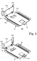
- the support slide 8 is according 3 provided at the edge with bent tabs 9, which form guide rails for the edge of the shell connector 5.
- the support plate 8.1 After inserting the surface element 4 in the leg 5.2 or the support plate 8.1, which is initially kept at a distance, the support plate 8.1 is moved up against the second leg 5.2 of the shell connector 5. In order to then hold it in this position, the shell connector 5 is provided with locking recesses 10 on its edges extending perpendicularly to the frame shells 1, 2, into which latching tongues 11 provided on the support slide 8 engage, which then allow the support slide 8 to be released or moved back lock out.
- the second leg 5.2 of the shell connector 5 protrudes into a groove 12 of the sealing strip 13 adjacent to the surface element 4, whereby the edge of the leg 5.2 is covered, ie not visible from the inside.
- the two frame shells 1, 2 are connected to one another via insulating bars 14;
- the shell connector 5 can also be used in those frame elements in which the frame shells 1.2 are connected to one another via fixed frame profile parts 15, as can be seen from FIG figure 5 emerges.
- Abut surface element 4 and allow a more flexible adjustment instead of the rigid leg 5.2.
- connection strips 7 carrying the shell connectors 5 are also used for fastening the glazing beads, on which the glazing beads 3 are supported with a partially open, hollow round profile 16--towards the connection strip 7. As emerges from the figure 1 recognize leaves, the assembly of the glazing beads 3 can then be more difficult if the retaining clips 6 have a size or shape that no longer allow recording within the hollow round profile 16.
- the shell connector 5 shown can also be used entirely without a support slide 8.1 or without a support plate 5.2, particularly in the case of blind frames or fixed panels on the side facing away from the retaining strips 3, i.e. on the reveal side, since there is no space for a support slide 8.1 or is a support plate 5.2; nevertheless, this achieves a fire-resistant effect.
Landscapes
- Engineering & Computer Science (AREA)
- Civil Engineering (AREA)
- Structural Engineering (AREA)
- Securing Of Glass Panes Or The Like (AREA)
- Special Wing (AREA)
Description
- Rahmenelement in bevorzugt brandgeschützter Ausführung, insbesondere in Form einer Brandschutztür, bestehend aus einer inneren und einer äußeren Rahmenschale die beide auf Abstand miteinander verbunden sind und zwischen sich ein plattenförmiges Flächenelement, insbesondere ein Glaselement aufnehmen, sowie mit zum Flächenelement hin vorstehenden Halteleisten, auch in Form von lösbaren Glashalteleisten, die zwischen sich das Flächenelement halten, wobei die innere und die äußere Rahmenschale zusätzlich über wenigstens einen brandresistenten Schalenverbinder miteinander verbunden sind.
- Derartige Rahmenelemente sind in unterschiedlichen Ausführungsformen aus dem Stand der Technik bekannt, wobei der Schalenverbinder die Aufgabe hat, im Brandfall eine Trennung der beiden Rahmenschalen voneinander und damit ein Lösen des plattenförmigen Flächenelements zu verhindern. Für die Befestigung der Schalenverbinder bestehen unterschiedliche Möglichkeiten; häufig erfolgt ein Verschrauben an wenigstens einer der beiden Rahmenschalen, was beim Aufbau des Rahmenelements zu einem erhöhten Zeit- und Arbeitsaufwand führt. Derartige Rahmenelemente sind insbesondere aus
DE 20 2006 004 606 U1 undEP 2 634 347 A1 bekannt. AuchEP 1 793 073 A2 beschreibt ein Gebäudeelement in brandgeschützter Ausführung. - Der Erfindung liegt die Aufgabe zugrunde, ein Rahmenelement der eingangs genannten Art so zu verbessern, dass der Schalenverbinder auf einfache Weise montiert werden kann, gleichwohl aber im Brandfall eine optimale Funktions- und Schutzwirkung entfaltet.
- Diese Aufgabe wird nach der Erfindung dadurch gelöst, dass der Schalenverbinder als Blechwinkel ausgebildet ist, dessen erster Schenkel mit Halteklammern zur Befestigung an von den Rahmenschalen zum Flächenelement hin vorstehenden, vorzugsweise T-profilförmigen Anschlussleisten versehen ist, während der zweite Schenkel eine Anlagefläche für das Flächenelement bildet, wobei auf dem ersten Schenkel ein Stützschieber verschieb- und feststellbar angeordnet ist, der ein zum zweiten Schenkel des Schalenverbinders paralleles Stützblech für das Flächenelement aufweist und wobei der zweite Schenkel ebenfalls verschiebbar auf dem ersten Schenkel angeordnet und durch einen weiteren Stützschieber ausgebildet ist
- Der durch die Erfindung erreichte Vorteil besteht zunächst im Wesentlichen darin, dass der Schalenverbinder unmittelbar an den Anschlussleisten, zum Beispiel durch Aufrasten, angebracht werden kann, wodurch die beiden Rahmenschalen, insbesondere wenn diese durch hitzeempfindliche Dämmstege miteinander verbunden sind, auch im Brandfall zusammengehalten werden. Hinzukommt, dass der zweite Schenkel des Schalenverbinders gemeinsam mit dem Stützblech des Stützschiebers das Flächenelement klammerartig zwischen sich halten, wodurch ein zusätzlicher Schutz gegen Zerstörung des Rahmenelements im Brandfall, z.B. infolge hitzebedingter Krümmung des Flächenelements, gegeben ist.
- In bevorzugter Ausführungsform der Erfindung sind die Halteklammern des Schalenverbinders derart ausgebildet, dass sie die Anschlussleisten jeweils auf ihren einander abgewandten Seiten umgreifen, wodurch die Möglichkeit besteht, den Schalenverbinder auf die T-profilförmige Anschlussleisten aufzurasten.
- Es besteht im Rahmen der Erfindung jedoch auch die Möglichkeit, dass auf der dem zweiten Schenkel des Schalenverbinders abgewandten Seite eine zweite Halteklammervorgesehen ist und die Anschlussleiste zwischen diesen beiden Halteklammern aufgenommen ist. Damit wird eine erhöhte Stabilität insbesondere auch bei erhöhten mechanischen Belastungen sichergestellt.
- Die Halteklammern können in besonders einfacher und daher im Rahmen der Erfindung bevorzugter Ausgestaltung am Rand des Schalenverbinders angeschlossen oder aus diesem freigeschnitten sein.
- Der Stützschieber umgreift den Rand des Schalenverbinders jeweils mit laschenförmig umgebogenen Führungsleisten, wodurch dieser auf dem Schalenverbinder verschoben werden kann.
- Desweiteren ist der Schalenverbinder an seinen senkrecht zu den Rahmenschalen sich erstreckenden Rändern mit Sperrausnehmungen versehen, in die am Stützschieber vorgesehene, eine Rückstellung des Stützschiebers sperrende Rastzungen eingreifen. Hierdurch besteht die Möglichkeit, den Stützschieber zunächst so auf dem Schalenverbinder anzuordnen, dass der das Flächenelement zwischen sich aufnehmende Schenkel einerseits und das Stützblech andererseits zunächst maximalen Abstand voneinander aufweisen und nach Montage des Flächenelements der Stützschieber an das Flächenelement herangeschoben wird, worauf die Rastzungen den Stützschieber in dieser Position arretieren.
- Von Vorteil ist weiter, wenn der zweite Schenkel des Schalenverbinders in eine Nut der dem Flächenelement anliegenden Dichtleiste vorsteht und zusätzlich ein dazu parallel angebrachter Steg in eine Nut an einer der Glashalteleisten einsteht. Dabei kann diese Dichtleiste insbesondere eine den zweiten Schenkel hinreichend weit überlappende Dichtungslippe aufweisen, wodurch der Rand des zweiten Schenkels - durch Spiegelung im Glas - nicht sichtbar ist.
- Von besonderem Vorteil bzw. Wirkung ist der Schalenverbinder bei Rahmenschalen, die über Isolierstege miteinander verbunden sind; grundsätzlich ist der Einsatz jedoch auch dann möglich, wenn die Rahmenschalen über feste Rahmenprofilteile miteinander verbunden sind.
- Erfindungsgemäß ist der zweite Schenkel des Schalenverbinders ebenfalls verschiebbar durch einen weiteren Stützschieber ausgebildet.
- Schließlich ist das Rahmenelement derart gestaltet, dass die das Flächenelement haltenden Glasleisten sich an den die Schalenverbinder tragenden Anschlussleisten mit einem teilweise offenen, hohlförmigen Rundprofil abstützen. In den Bereichen, in denen Schalenverbinder an den Anschlussleisten angeschlossen sind, weisen diese jedoch - bedingt durch den Schalenverbinder - eine größer Breite auf, so dass dort die Anbringung der Glasleiste erschwert sein kann. Daher sieht die Erfindung für die Vereinfachung der Montage der Glasleisten ein Verfahren vor, bei welchem der Schalenverbinder auf die Anschlussleisten aufgeclipst oder aufgesetzt und danach durch Umbiegen der Halteklammern befestigt wird, wobei anschließend die Halteklammer auf der der Glasleiste zugewandten Seite zusammen mit der Anschlussleiste derart umgeformt wird, dass sich für die Glasleiste die gleiche Abstützposition wie ohne aufgesetzten Schalenverbinder ergibt. Dadurch ist die Montage der Glasleiste in gleicher Weise möglich wie ohne angebrachte Halteklammer.
- Im Folgenden wird die Erfindung an einem in der Zeichnung dargestellten Ausführungsbeispiel näher erläutert; es zeigen:
-
Fig. 1 einen Querschnitt durch ein nur teilweise wiedergegebenes Rahmenelement, -
Fig. 2 in den Teilfiguren a) und b) den Schalenverbinder in perspektivischer Darstellung -
Fig. 3 in den Teilfiguren a) und b) den auf den Schalenverbinder aufzusetzenden Stützschieber in perspektivischer Darstellung, in den Teilfiguren c) und d) in Drauf- und Seitenansicht, -
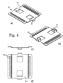
Fig. 4 in den Teilfiguren a) und b) eine erfindungsgemäße Ausgestaltung des Schalenverbinders für zwei auf zusetzende, einander gegenüberstehende Stützschieber, -
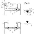
Fig. 5 in den Teilfiguren a) bis d) das Verprägen der Anschlussleiste gemeinsam mit der Halteklammer des Schalenverbinders. - Das in der Zeichnung nur teilweise wiedergegebene Rahmenelement ist in brandgeschützter Ausführung gezeigt und ist beispielsweise für eine Brandschutztür vorgesehen. Es besteht aus einer inneren 1 und einer äußeren 2 Rahmenschale, die beide auf Abstand miteinander verbunden sind und zwischen sich ein plattenförmiges Flächenelement, also beispielsweise ein Glaselement aufnehmen. Weiter sind zum Flächenelement 4 hin vorstehende Halteleisten 3 vorgesehen, von denen eine oder auch beide als lösbare Glashalteleisten ausgebildet sein können und zwischen sich das Flächenelement 4 halten.
- Die innere und die äußere Rahmenschale 1, 2 sind zusätzlich durch wenigstens einen brandresistenten Schalenverbinder 5 miteinander verbunden. Dieser Schalenverbinders 5 ist als Blechwinkel ausgebildet, wobei der erste Schenkel 5.1 mit Halteklammern 6 versehen ist, die zur Befestigung an vorzugsweise T-profilförmigen Anschlussleisten 7 vorgesehen sind, die von den Rahmenschalen 1, 2 zum Flächenelement 4 hin vorstehen.
- Der zweite Schenkel 5.2 des Schalenverbinders 5 bildet dagegen eine Anlagefläche für das Flächenelement 4, wobei auf dem ersten Schenkel 5.1 ein Stützschieber 8 verschieb- und feststellbar angeordnet ist, der ein zum zweiten Schenkel 5.2 des Schalenverbinders 5 paralleles Stützblech 8.1 für das Flächenelement 4 aufweist. Während der Schalenverbinder 5 als solcher dafür sorgt, dass - im Brandfall - die beiden Rahmenschalen 1, 2 aneinander gehalten werden, sorgen der zweite Schenkel 5.2 des Schalenverbinders 5 zusammen mit dem Stützblech 8.1 des Stützschiebers 8 dafür, dass das Flächenelement 4 zusätzlich Halt erfährt, wodurch einer hitzebedingten Krümmung des Flächenelements entgegengewirkt wird.
- Wie sich insbesondere aus der
Figur 1 ergibt, umgreifen die Halteklammern 6 des Schalenverbinders 5 die Anschlussleisten 7 jeweils auf ihren einander abgewandten Seiten. Zusätzlich ist auf der dem zweiten Schenkel 5.2 des Schalenverbinders 5 abgewandten Seite eine zweite Halteklammer 6 vorgesehen, wodurch die Anschlussleiste 7 zwischen diesen beiden Halteklammern 6 aufgenommen ist. - Wie aus der
Figur 2 zu ersehen ist, sind die Halteklammern 6 am Rand des Schalenverbinders 5 angeschlossen bzw. aus diesem freigeschnitten. - Der Stützschieber 8 ist gemäß
Fig. 3 randseitig mit umgebogenen Laschen 9 versehen, die Führungsleisten für den Rand des Schalenverbinders 5 bilden. - Nach Einsetzen des Flächenelements 4 in den zunächst auf Abstand gehaltenen Schenkel 5.2 bzw. des Stützblech 8.1 wird das Stützblech 8.1 gegen den zweiten Schenkel 5.2 des Schalenverbinders 5 herangefahren. Um diesen dann in dieser Stellung zu halten, ist der Schalenverbinder 5 an seinen senkrecht zu den Rahmenschalen 1, 2 sich erstreckenden Rändern mit Sperrausnehmungen 10 versehen, in die am Stützschieber 8 vorgesehene Rastzungen 11 eingreifen, die dann ein Lösen bzw. Zurückfahren des Stützschiebers 8 sperren.
- Wie weiter aus der
Figur 1 ersichtlich, steht der zweite Schenkel 5.2 des Schalenverbinders 5 in eine Nut 12 der dem Flächenelement 4 anliegenden Dichtleiste 13 vor, wodurch der Rand des Schenkels 5.2 abgedeckt, also von innen nicht sichtbar ist. - Wie weiter aus der
Fig. 1 hervorgeht, ist an dem zweiten Schenkel 5.2 ein dazu parallel angebrachter Steg 5.3 vorhanden, welcher in eine Nut 3.1 an einer der Glasleisten 3 einsteht. - Bei dem in der
Figur 1 dargestellten Rahmenelement sind die beiden Rahmenschalen 1, 2 über Isolierstege 14 miteinander verbunden; grundsätzlich kann der Schalenverbinder 5 jedoch auch bei solchen Rahmenelementen eingesetzt werden, bei denen die Rahmenschalen 1,2 über feste Rahmenprofilteile 15 miteinander verbunden sind, wie dies aus derFigur 5 hervorgeht. - In
Fig. 4 ist eine erfindungsgemäße Ausgestaltung des Schalenverbinders 5 gezeigt, mit dessen Hilfe es möglich ist, zwei Stützschieber 8 zu verwenden, die dann beidseits des - Flächenelements 4 anliegen und eine flexiblere Anpassung statt des starren Schenkels 5.2 ermöglichen.
- Für die Befestigung der Glasleisten dienen ebenfalls die die Schalenverbinder 5 tragenden Anschlussleisten 7, an denen sich die Glasleisten 3 mit einem teilweise - zur Anschlussleiste 7 hin - offenen, hohlförmigen Rundprofil 16 abstützen. Wie sich aus der
Figur 1 erkennen lässt, kann die Montage der Glasleisten 3 dann erschwert sein, wenn die Halteklammern 6 eine Größe oder Form besitzen, die eine Aufnahme innerhalb des hohlförmigen Rundprofils 16 nicht mehr erlauben. - Der in der
Fig. 4 gezeigte Schalenverbinder 5 kann in einer nicht beanspruchten Ausführungsform auch gänzlich ohne Stützschieber 8.1 bzw. ohne Stützblech 5.2 eingesetzt werden, insbesondere bei Blendrahmen oder Festfeldern auf der den Halteleisten 3 abgewandten Seite, also auf der Laibungsseite, da dort kein Raum für einen Stützschieber 8.1 bzw. ein Stützblech 5.2 ist; gleichwohl wird dadurch eine brandresistente Wirkung erreicht. - In diesem Fall kommt ein Verfahren zum Einsatz, bei welchem zunächst die Schalenverbinder 5 auf die Anschlussleisten 7 aufgeclipst oder aufgesetzt und durch Umbiegen der Halteklammern 6 befestigt werden, worauf die Halteklammer 6 auf der der Glasleiste 3 zugewandten Seite zusammen mit der Anschlussleiste 7 derart umgeformt wird, dass sich für die Glasleiste die gleiche Abstützposition wie ohne aufgesetzten Schalenverbinder ergibt. Dies ist im Einzelnen aus den Darstellungen der
Figur 5 ersichtlich.
Claims (10)
- Rahmenelement in bevorzugt brandgeschützter Ausführung, insbesondere in Form einer Brandschutztür, bestehend aus einer inneren (1) und einer äußeren (2) Rahmenschale, die beide auf Abstand miteinander verbunden sind und zwischen sich ein plattenförmiges Flächenelement (4) , insbesondere ein Glaselement aufnehmen, sowie mit zum Flächenelement (4) hin vorstehenden Halteleisten (3), auch in Form von lösbaren Glashalteleisten, die zwischen sich das Flächenelement (4) halten, wobei die innere und die äußere Rahmenschale (1, 2) zusätzlich über wenigstens einen brandresistenten Schalenverbinder (5) miteinander verbunden sind, wobei der Schalenverbinder (5) als Blechwinkel ausgebildet ist, dessen erster Schenkel (5.1) mit Halteklammern (6) zur Befestigung an von den Rahmenschalen (1, 2) zum Flächenelement (4) hin vorstehenden, vorzugsweise T-profilförmigen Anschlußleisten (7) versehen ist, während der zweite Schenkel (5.2) eine Anlagefläche für das Flächenelement (4) bildet, wobei auf dem ersten Schenkel (5.1) ein Stützschieber (8) verschieb- und feststellbar angeordnet ist, der ein zum zweiten Schenkel (5.2) des Schalenverbinders (5) paralleles Stützblech (8.1) für das Flächenelement (4) aufweist, dadurch gekennzeichnet, dass der zweite Schenkel ebenfalls verschiebbar auf dem ersten Schenkel angeordnet und durch einen weiteren Stützschieber (8) ausgebildet ist.
- Rahmenelement nach Anspruch 1, dadurch gekennzeichnet, dass die Halteklammern (6) des Schalenverbinders (5) die Anschlußleisten (7) jeweils auf ihren einander abgewandten Seiten umgreifen.
- Rahmenelement nach Anspruch 1 oder 2, dadurch gekennzeichnet, dass auf der dem zweiten Schenkel (5.2) des Schalenverbinders (5) abgewandten Seite eine zweite Halteklammer (6) vorgesehen ist und die Anschlußleiste (7) zwischen diesen beiden Halteklammern (6) aufgenommen ist.
- Rahmenelement nach einem der Ansprüche 1 bis 3, dadurch gekennzeichnet, dass die Halteklammern (6) am Rand des Schalenverbinders (5) angeschlossen oder aus diesem freigeschnitten sind.
- Rahmenelement nach einem der Ansprüche 1 bis 4, dadurch gekennzeichnet, dass die Stützschieber (8) den Rand des Schalenverbinders (5) jeweils mit Führungsleisten (9) umgreifen.
- Rahmenelement nach einem der Ansprüche 1 bis 5, dadurch gekennzeichnet, dass der Schalenverbinder (5) an seinen senkrecht zu den Rahmenschalen (1, 2) sich erstreckenden Rändern mit Sperrausnehmungen (10) versehen ist, in die am Stützschieber (8) vorgesehene, ein Lösen des Stützschiebers (8) sperrende Rastzungen (11) eingreifen.
- Rahmenelement nach einem der Ansprüche 1 bis 6, dadurch gekennzeichnet, dass der zweite Schenkel (5.2) des Schalenverbinders (5) in eine Nut (12) der dem Flächenelement (4) anliegenden Dichtleiste (13) vorsteht, und dass ein dazu parallel angebrachter Steg (5.3) in eine Nut (3.1) an einer der Glashalteleisten (3) einsteht.
- Rahmenelement nach einem der Ansprüche 1 bis 7, dadurch gekennzeichnet, dass die beiden Rahmenschalen (1, 2) über Isolierstege (14) oder Rahmenprofilteile (15) miteinander verbunden sind.
- Rahmenelement nach einem der Ansprüche 1 bis 8,dadurch gekennzeichnet, dass die Glasleisten (3) sich an den die Schalenverbinder (5) tragenden Anschlußleisten (7) mit einem teilweise offenen, hohlförmigen Rundprofil (16) abstützen.
- Verfahren zum Anschluß eines Schalenverbinders an einem Rahmenelement nach den Ansprüchen 1 bis 9, dadurch gekennzeichnet, dass der Schalenverbinder (5) auf die Anschlußleisten (7) aufgeklipst oder aufgesetzt und durch umbiegen der Halteklammern (6) befestigt wird, und dass anschließend die Halteklammer (6) auf der der Glasleiste (3) zugewandten Seite zusammen mit der Anschlussleiste (7) derart umgeformt wird, dass sich für die Glasleiste (3) die gleiche Abstützposition wie ohne aufgesetzten Schalenverbinder (5) ergibt.
Applications Claiming Priority (1)
| Application Number | Priority Date | Filing Date | Title |
|---|---|---|---|
| DE102018007897.4A DE102018007897A1 (de) | 2018-10-06 | 2018-10-06 | Rahmenelement |
Publications (3)
| Publication Number | Publication Date |
|---|---|
| EP3633131A1 EP3633131A1 (de) | 2020-04-08 |
| EP3633131B1 true EP3633131B1 (de) | 2023-06-14 |
| EP3633131C0 EP3633131C0 (de) | 2023-06-14 |
Family
ID=68136124
Family Applications (1)
| Application Number | Title | Priority Date | Filing Date |
|---|---|---|---|
| EP19000441.6A Active EP3633131B1 (de) | 2018-10-06 | 2019-10-01 | Rahmenelement |
Country Status (3)
| Country | Link |
|---|---|
| EP (1) | EP3633131B1 (de) |
| DE (1) | DE102018007897A1 (de) |
| PL (1) | PL3633131T3 (de) |
Families Citing this family (4)
| Publication number | Priority date | Publication date | Assignee | Title |
|---|---|---|---|---|
| BE1027713B1 (nl) * | 2019-10-25 | 2021-05-27 | Reynaers Aluminium Nv | Brandbestendige paneelconstructie voor gebouwen en brandbestendige glasklem daarbij toegepast |
| WO2021185941A1 (en) * | 2020-03-19 | 2021-09-23 | Assa Abloy Entrance Systems Ab | A panel frame and a method for providing a panel |
| US11643866B1 (en) * | 2020-12-29 | 2023-05-09 | Andersen Corporation | Retention clip assemblies, retention systems and methods |
| US20240183216A1 (en) * | 2022-12-02 | 2024-06-06 | Andersen Corporation | Self-cinching device for fenestration units |
Family Cites Families (3)
| Publication number | Priority date | Publication date | Assignee | Title |
|---|---|---|---|---|
| DE102005057389B3 (de) * | 2005-11-30 | 2007-08-16 | Hydro Building Systems Gmbh | Gebäudeelement in brandgeschützter Ausführung |
| DE202006004606U1 (de) * | 2006-03-21 | 2006-06-08 | SCHÜCO International KG | Rahmenkonstruktion |
| DE102012004297B4 (de) * | 2012-03-01 | 2019-01-10 | Hueck Gmbh & Co. Kg | Profilanordnung und Rahmenkonstruktion |
-
2018
- 2018-10-06 DE DE102018007897.4A patent/DE102018007897A1/de active Pending
-
2019
- 2019-10-01 PL PL19000441.6T patent/PL3633131T3/pl unknown
- 2019-10-01 EP EP19000441.6A patent/EP3633131B1/de active Active
Also Published As
| Publication number | Publication date |
|---|---|
| DE102018007897A1 (de) | 2020-04-09 |
| PL3633131T3 (pl) | 2023-12-04 |
| EP3633131A1 (de) | 2020-04-08 |
| EP3633131C0 (de) | 2023-06-14 |
Similar Documents
| Publication | Publication Date | Title |
|---|---|---|
| DE60304318T2 (de) | Befestigung einer rohrklemme | |
| AT515988B1 (de) | Leuchte, Anordnung für eine Rasterdecke, Verfahren zum Montieren einer Leuchte, Verfahren zum Demontieren einer Leuchte, sowie Demontagewerkzeug | |
| EP3633131A1 (de) | Rahmenelement | |
| DE202007001781U1 (de) | Schubkasten | |
| EP3746627B1 (de) | Montageträger zur montage von oberschienen von jalousien | |
| DE102016103985A1 (de) | Längenvariable Schutzabdeckung mit Faltenelement | |
| WO2018035546A1 (de) | Montagehilfe | |
| EP0650317A1 (de) | Baugruppenträger | |
| EP2754805B1 (de) | Riegelstange für einen Riegelstangenbeschlag | |
| EP2754803B1 (de) | Riegelstangenbeschlag für ein Fenster oder eine Tür und Riegelstange für einen solchen Riegelstangenbeschlag | |
| DE102008011672A1 (de) | Kabelführungsvorrichtung | |
| DE102013112761A1 (de) | Haltevorrichtung für ein Gehäuse und Verfahren zur Montage des Gehäuses unter Verwendung der Haltevorrichtung | |
| DE29718854U1 (de) | Profilrahmen, insbesondere U-Profilrahmen zur Halterung von Flächenelementen wie Glasscheiben, Kunststoffplatten o.dgl. | |
| EP2594165B1 (de) | Klemmhalterung zur Befestigung eines Objekts, insbesondere einer Seilspannvorrichtung für eine Sonnen- und/oder Blickschutzvorrichtung, an einem Fenster- oder Türrahmen | |
| EP2273638A2 (de) | Klammer für Kabelkanäle zur Kaschierung von Schnittkanten | |
| EP2460947A2 (de) | Verglasung | |
| EP2620579B1 (de) | Verbindungselement zur Verbindung von Profilteilen | |
| DE102017221802A1 (de) | Befestigungsklemme und Profilstabsystem | |
| EP3408591B1 (de) | Halteeinrichtung zur befestigung von verkleidungsteilen an plattenheizkörpern und heizkörper | |
| EP3336275B1 (de) | Markisentuch-fixier- und -führungseinrichtung | |
| AT515601A2 (de) | System zur Aufnahme von Lichtmodulen sowie Verfahren für dessen Herstellung | |
| DE102016104405A1 (de) | Verfahren zur Montage einer Pfosten-Riegel-Konstruktion und Montagehilfe | |
| EP2639909B1 (de) | Kabelkanalsystem | |
| EP2509176B1 (de) | Montagesystem zur Verschiebesicherung und Schnittkaschierung von Oberteilen und Elektroinstallationsgeräten bei Leitungsführungskanälen | |
| EP2240651A1 (de) | Profilleistenvorrichtung |
Legal Events
| Date | Code | Title | Description |
|---|---|---|---|
| PUAI | Public reference made under article 153(3) epc to a published international application that has entered the european phase |
Free format text: ORIGINAL CODE: 0009012 |
|
| STAA | Information on the status of an ep patent application or granted ep patent |
Free format text: STATUS: THE APPLICATION HAS BEEN PUBLISHED |
|
| AK | Designated contracting states |
Kind code of ref document: A1 Designated state(s): AL AT BE BG CH CY CZ DE DK EE ES FI FR GB GR HR HU IE IS IT LI LT LU LV MC MK MT NL NO PL PT RO RS SE SI SK SM TR |
|
| AX | Request for extension of the european patent |
Extension state: BA ME |
|
| STAA | Information on the status of an ep patent application or granted ep patent |
Free format text: STATUS: REQUEST FOR EXAMINATION WAS MADE |
|
| 17P | Request for examination filed |
Effective date: 20201005 |
|
| STAA | Information on the status of an ep patent application or granted ep patent |
Free format text: STATUS: EXAMINATION IS IN PROGRESS |
|
| 17Q | First examination report despatched |
Effective date: 20201124 |
|
| GRAP | Despatch of communication of intention to grant a patent |
Free format text: ORIGINAL CODE: EPIDOSNIGR1 |
|
| STAA | Information on the status of an ep patent application or granted ep patent |
Free format text: STATUS: GRANT OF PATENT IS INTENDED |
|
| GRAJ | Information related to disapproval of communication of intention to grant by the applicant or resumption of examination proceedings by the epo deleted |
Free format text: ORIGINAL CODE: EPIDOSDIGR1 |
|
| GRAP | Despatch of communication of intention to grant a patent |
Free format text: ORIGINAL CODE: EPIDOSNIGR1 |
|
| INTG | Intention to grant announced |
Effective date: 20210907 |
|
| INTG | Intention to grant announced |
Effective date: 20210924 |
|
| RIN1 | Information on inventor provided before grant (corrected) |
Inventor name: GOETZ, PETER |
|
| GRAJ | Information related to disapproval of communication of intention to grant by the applicant or resumption of examination proceedings by the epo deleted |
Free format text: ORIGINAL CODE: EPIDOSDIGR1 |
|
| STAA | Information on the status of an ep patent application or granted ep patent |
Free format text: STATUS: EXAMINATION IS IN PROGRESS |
|
| GRAP | Despatch of communication of intention to grant a patent |
Free format text: ORIGINAL CODE: EPIDOSNIGR1 |
|
| STAA | Information on the status of an ep patent application or granted ep patent |
Free format text: STATUS: GRANT OF PATENT IS INTENDED |
|
| INTC | Intention to grant announced (deleted) | ||
| INTG | Intention to grant announced |
Effective date: 20220217 |
|
| GRAS | Grant fee paid |
Free format text: ORIGINAL CODE: EPIDOSNIGR3 |
|
| GRAJ | Information related to disapproval of communication of intention to grant by the applicant or resumption of examination proceedings by the epo deleted |
Free format text: ORIGINAL CODE: EPIDOSDIGR1 |
|
| GRAL | Information related to payment of fee for publishing/printing deleted |
Free format text: ORIGINAL CODE: EPIDOSDIGR3 |
|
| STAA | Information on the status of an ep patent application or granted ep patent |
Free format text: STATUS: EXAMINATION IS IN PROGRESS |
|
| GRAP | Despatch of communication of intention to grant a patent |
Free format text: ORIGINAL CODE: EPIDOSNIGR1 |
|
| STAA | Information on the status of an ep patent application or granted ep patent |
Free format text: STATUS: GRANT OF PATENT IS INTENDED |
|
| INTC | Intention to grant announced (deleted) | ||
| INTG | Intention to grant announced |
Effective date: 20220727 |
|
| GRAJ | Information related to disapproval of communication of intention to grant by the applicant or resumption of examination proceedings by the epo deleted |
Free format text: ORIGINAL CODE: EPIDOSDIGR1 |
|
| GRAL | Information related to payment of fee for publishing/printing deleted |
Free format text: ORIGINAL CODE: EPIDOSDIGR3 |
|
| STAA | Information on the status of an ep patent application or granted ep patent |
Free format text: STATUS: EXAMINATION IS IN PROGRESS |
|
| GRAP | Despatch of communication of intention to grant a patent |
Free format text: ORIGINAL CODE: EPIDOSNIGR1 |
|
| STAA | Information on the status of an ep patent application or granted ep patent |
Free format text: STATUS: GRANT OF PATENT IS INTENDED |
|
| INTC | Intention to grant announced (deleted) | ||
| INTG | Intention to grant announced |
Effective date: 20230104 |
|
| GRAA | (expected) grant |
Free format text: ORIGINAL CODE: 0009210 |
|
| STAA | Information on the status of an ep patent application or granted ep patent |
Free format text: STATUS: THE PATENT HAS BEEN GRANTED |
|
| AK | Designated contracting states |
Kind code of ref document: B1 Designated state(s): AL AT BE BG CH CY CZ DE DK EE ES FI FR GB GR HR HU IE IS IT LI LT LU LV MC MK MT NL NO PL PT RO RS SE SI SK SM TR |
|
| REG | Reference to a national code |
Ref country code: CH Ref legal event code: EP |
|
| REG | Reference to a national code |
Ref country code: DE Ref legal event code: R096 Ref document number: 502019008148 Country of ref document: DE |
|
| REG | Reference to a national code |
Ref country code: AT Ref legal event code: REF Ref document number: 1579354 Country of ref document: AT Kind code of ref document: T Effective date: 20230715 |
|
| U01 | Request for unitary effect filed |
Effective date: 20230714 |
|
| U07 | Unitary effect registered |
Designated state(s): AT BE BG DE DK EE FI FR IT LT LU LV MT NL PT SE SI Effective date: 20230721 |
|
| REG | Reference to a national code |
Ref country code: LT Ref legal event code: MG9D |
|
| REG | Reference to a national code |
Ref country code: NO Ref legal event code: T2 Effective date: 20230614 |
|
| PG25 | Lapsed in a contracting state [announced via postgrant information from national office to epo] |
Ref country code: ES Free format text: LAPSE BECAUSE OF FAILURE TO SUBMIT A TRANSLATION OF THE DESCRIPTION OR TO PAY THE FEE WITHIN THE PRESCRIBED TIME-LIMIT Effective date: 20230614 |
|
| U20 | Renewal fee for the european patent with unitary effect paid |
Year of fee payment: 5 Effective date: 20231016 |
|
| PG25 | Lapsed in a contracting state [announced via postgrant information from national office to epo] |
Ref country code: RS Free format text: LAPSE BECAUSE OF FAILURE TO SUBMIT A TRANSLATION OF THE DESCRIPTION OR TO PAY THE FEE WITHIN THE PRESCRIBED TIME-LIMIT Effective date: 20230614 Ref country code: HR Free format text: LAPSE BECAUSE OF FAILURE TO SUBMIT A TRANSLATION OF THE DESCRIPTION OR TO PAY THE FEE WITHIN THE PRESCRIBED TIME-LIMIT Effective date: 20230614 Ref country code: GR Free format text: LAPSE BECAUSE OF FAILURE TO SUBMIT A TRANSLATION OF THE DESCRIPTION OR TO PAY THE FEE WITHIN THE PRESCRIBED TIME-LIMIT Effective date: 20230915 |
|
| PG25 | Lapsed in a contracting state [announced via postgrant information from national office to epo] |
Ref country code: SK Free format text: LAPSE BECAUSE OF FAILURE TO SUBMIT A TRANSLATION OF THE DESCRIPTION OR TO PAY THE FEE WITHIN THE PRESCRIBED TIME-LIMIT Effective date: 20230614 |
|
| PG25 | Lapsed in a contracting state [announced via postgrant information from national office to epo] |
Ref country code: IS Free format text: LAPSE BECAUSE OF FAILURE TO SUBMIT A TRANSLATION OF THE DESCRIPTION OR TO PAY THE FEE WITHIN THE PRESCRIBED TIME-LIMIT Effective date: 20231014 |
|
| PG25 | Lapsed in a contracting state [announced via postgrant information from national office to epo] |
Ref country code: SM Free format text: LAPSE BECAUSE OF FAILURE TO SUBMIT A TRANSLATION OF THE DESCRIPTION OR TO PAY THE FEE WITHIN THE PRESCRIBED TIME-LIMIT Effective date: 20230614 Ref country code: SK Free format text: LAPSE BECAUSE OF FAILURE TO SUBMIT A TRANSLATION OF THE DESCRIPTION OR TO PAY THE FEE WITHIN THE PRESCRIBED TIME-LIMIT Effective date: 20230614 Ref country code: RO Free format text: LAPSE BECAUSE OF FAILURE TO SUBMIT A TRANSLATION OF THE DESCRIPTION OR TO PAY THE FEE WITHIN THE PRESCRIBED TIME-LIMIT Effective date: 20230614 Ref country code: IS Free format text: LAPSE BECAUSE OF FAILURE TO SUBMIT A TRANSLATION OF THE DESCRIPTION OR TO PAY THE FEE WITHIN THE PRESCRIBED TIME-LIMIT Effective date: 20231014 Ref country code: CZ Free format text: LAPSE BECAUSE OF FAILURE TO SUBMIT A TRANSLATION OF THE DESCRIPTION OR TO PAY THE FEE WITHIN THE PRESCRIBED TIME-LIMIT Effective date: 20230614 |
|
| REG | Reference to a national code |
Ref country code: DE Ref legal event code: R097 Ref document number: 502019008148 Country of ref document: DE |
|
| PLBE | No opposition filed within time limit |
Free format text: ORIGINAL CODE: 0009261 |
|
| STAA | Information on the status of an ep patent application or granted ep patent |
Free format text: STATUS: NO OPPOSITION FILED WITHIN TIME LIMIT |
|
| 26N | No opposition filed |
Effective date: 20240315 |
|
| PG25 | Lapsed in a contracting state [announced via postgrant information from national office to epo] |
Ref country code: MC Free format text: LAPSE BECAUSE OF FAILURE TO SUBMIT A TRANSLATION OF THE DESCRIPTION OR TO PAY THE FEE WITHIN THE PRESCRIBED TIME-LIMIT Effective date: 20230614 |
|
| GBPC | Gb: european patent ceased through non-payment of renewal fee |
Effective date: 20231001 |
|
| PG25 | Lapsed in a contracting state [announced via postgrant information from national office to epo] |
Ref country code: GB Free format text: LAPSE BECAUSE OF NON-PAYMENT OF DUE FEES Effective date: 20231001 |
|
| PG25 | Lapsed in a contracting state [announced via postgrant information from national office to epo] |
Ref country code: GB Free format text: LAPSE BECAUSE OF NON-PAYMENT OF DUE FEES Effective date: 20231001 |
|
| U20 | Renewal fee for the european patent with unitary effect paid |
Year of fee payment: 6 Effective date: 20240828 |
|
| PG25 | Lapsed in a contracting state [announced via postgrant information from national office to epo] |
Ref country code: IE Free format text: LAPSE BECAUSE OF NON-PAYMENT OF DUE FEES Effective date: 20231001 |
|
| PG25 | Lapsed in a contracting state [announced via postgrant information from national office to epo] |
Ref country code: IE Free format text: LAPSE BECAUSE OF NON-PAYMENT OF DUE FEES Effective date: 20231001 |
|
| PG25 | Lapsed in a contracting state [announced via postgrant information from national office to epo] |
Ref country code: CY Free format text: LAPSE BECAUSE OF FAILURE TO SUBMIT A TRANSLATION OF THE DESCRIPTION OR TO PAY THE FEE WITHIN THE PRESCRIBED TIME-LIMIT; INVALID AB INITIO Effective date: 20191001 |
|
| PG25 | Lapsed in a contracting state [announced via postgrant information from national office to epo] |
Ref country code: HU Free format text: LAPSE BECAUSE OF FAILURE TO SUBMIT A TRANSLATION OF THE DESCRIPTION OR TO PAY THE FEE WITHIN THE PRESCRIBED TIME-LIMIT; INVALID AB INITIO Effective date: 20191001 |
|
| U20 | Renewal fee for the european patent with unitary effect paid |
Year of fee payment: 7 Effective date: 20250828 |
|
| PGFP | Annual fee paid to national office [announced via postgrant information from national office to epo] |
Ref country code: NO Payment date: 20250919 Year of fee payment: 7 |
|
| PGFP | Annual fee paid to national office [announced via postgrant information from national office to epo] |
Ref country code: PL Payment date: 20250905 Year of fee payment: 7 |
|
| REG | Reference to a national code |
Ref country code: CH Ref legal event code: U11 Free format text: ST27 STATUS EVENT CODE: U-0-0-U10-U11 (AS PROVIDED BY THE NATIONAL OFFICE) Effective date: 20251101 |
|
| PG25 | Lapsed in a contracting state [announced via postgrant information from national office to epo] |
Ref country code: TR Free format text: LAPSE BECAUSE OF FAILURE TO SUBMIT A TRANSLATION OF THE DESCRIPTION OR TO PAY THE FEE WITHIN THE PRESCRIBED TIME-LIMIT Effective date: 20230614 |
|
| PGFP | Annual fee paid to national office [announced via postgrant information from national office to epo] |
Ref country code: CH Payment date: 20251101 Year of fee payment: 7 |