EP3632748A1 - Rear view assembly and vehicle with such rear view assembly - Google Patents
Rear view assembly and vehicle with such rear view assembly Download PDFInfo
- Publication number
- EP3632748A1 EP3632748A1 EP18198678.7A EP18198678A EP3632748A1 EP 3632748 A1 EP3632748 A1 EP 3632748A1 EP 18198678 A EP18198678 A EP 18198678A EP 3632748 A1 EP3632748 A1 EP 3632748A1
- Authority
- EP
- European Patent Office
- Prior art keywords
- rear view
- assembly
- mirror
- assemblies
- view
- Prior art date
- Legal status (The legal status is an assumption and is not a legal conclusion. Google has not performed a legal analysis and makes no representation as to the accuracy of the status listed.)
- Granted
Links
Images

Classifications
-
- B—PERFORMING OPERATIONS; TRANSPORTING
- B60—VEHICLES IN GENERAL
- B60R—VEHICLES, VEHICLE FITTINGS, OR VEHICLE PARTS, NOT OTHERWISE PROVIDED FOR
- B60R1/00—Optical viewing arrangements; Real-time viewing arrangements for drivers or passengers using optical image capturing systems, e.g. cameras or video systems specially adapted for use in or on vehicles
- B60R1/20—Real-time viewing arrangements for drivers or passengers using optical image capturing systems, e.g. cameras or video systems specially adapted for use in or on vehicles
- B60R1/22—Real-time viewing arrangements for drivers or passengers using optical image capturing systems, e.g. cameras or video systems specially adapted for use in or on vehicles for viewing an area outside the vehicle, e.g. the exterior of the vehicle
- B60R1/23—Real-time viewing arrangements for drivers or passengers using optical image capturing systems, e.g. cameras or video systems specially adapted for use in or on vehicles for viewing an area outside the vehicle, e.g. the exterior of the vehicle with a predetermined field of view
- B60R1/26—Real-time viewing arrangements for drivers or passengers using optical image capturing systems, e.g. cameras or video systems specially adapted for use in or on vehicles for viewing an area outside the vehicle, e.g. the exterior of the vehicle with a predetermined field of view to the rear of the vehicle
-
- B—PERFORMING OPERATIONS; TRANSPORTING
- B60—VEHICLES IN GENERAL
- B60R—VEHICLES, VEHICLE FITTINGS, OR VEHICLE PARTS, NOT OTHERWISE PROVIDED FOR
- B60R11/00—Arrangements for holding or mounting articles, not otherwise provided for
- B60R11/04—Mounting of cameras operative during drive; Arrangement of controls thereof relative to the vehicle
-
- B—PERFORMING OPERATIONS; TRANSPORTING
- B60—VEHICLES IN GENERAL
- B60R—VEHICLES, VEHICLE FITTINGS, OR VEHICLE PARTS, NOT OTHERWISE PROVIDED FOR
- B60R1/00—Optical viewing arrangements; Real-time viewing arrangements for drivers or passengers using optical image capturing systems, e.g. cameras or video systems specially adapted for use in or on vehicles
- B60R1/02—Rear-view mirror arrangements
- B60R1/06—Rear-view mirror arrangements mounted on vehicle exterior
-
- B—PERFORMING OPERATIONS; TRANSPORTING
- B60—VEHICLES IN GENERAL
- B60R—VEHICLES, VEHICLE FITTINGS, OR VEHICLE PARTS, NOT OTHERWISE PROVIDED FOR
- B60R1/00—Optical viewing arrangements; Real-time viewing arrangements for drivers or passengers using optical image capturing systems, e.g. cameras or video systems specially adapted for use in or on vehicles
- B60R1/12—Mirror assemblies combined with other articles, e.g. clocks
-
- H—ELECTRICITY
- H04—ELECTRIC COMMUNICATION TECHNIQUE
- H04N—PICTORIAL COMMUNICATION, e.g. TELEVISION
- H04N23/00—Cameras or camera modules comprising electronic image sensors; Control thereof
- H04N23/57—Mechanical or electrical details of cameras or camera modules specially adapted for being embedded in other devices
-
- H—ELECTRICITY
- H04—ELECTRIC COMMUNICATION TECHNIQUE
- H04N—PICTORIAL COMMUNICATION, e.g. TELEVISION
- H04N23/00—Cameras or camera modules comprising electronic image sensors; Control thereof
- H04N23/90—Arrangement of cameras or camera modules, e.g. multiple cameras in TV studios or sports stadiums
-
- B—PERFORMING OPERATIONS; TRANSPORTING
- B60—VEHICLES IN GENERAL
- B60R—VEHICLES, VEHICLE FITTINGS, OR VEHICLE PARTS, NOT OTHERWISE PROVIDED FOR
- B60R1/00—Optical viewing arrangements; Real-time viewing arrangements for drivers or passengers using optical image capturing systems, e.g. cameras or video systems specially adapted for use in or on vehicles
- B60R1/12—Mirror assemblies combined with other articles, e.g. clocks
- B60R2001/1253—Mirror assemblies combined with other articles, e.g. clocks with cameras, video cameras or video screens
-
- B—PERFORMING OPERATIONS; TRANSPORTING
- B60—VEHICLES IN GENERAL
- B60R—VEHICLES, VEHICLE FITTINGS, OR VEHICLE PARTS, NOT OTHERWISE PROVIDED FOR
- B60R2300/00—Details of viewing arrangements using cameras and displays, specially adapted for use in a vehicle
- B60R2300/30—Details of viewing arrangements using cameras and displays, specially adapted for use in a vehicle characterised by the type of image processing
- B60R2300/306—Details of viewing arrangements using cameras and displays, specially adapted for use in a vehicle characterised by the type of image processing using a re-scaling of images
-
- B—PERFORMING OPERATIONS; TRANSPORTING
- B60—VEHICLES IN GENERAL
- B60R—VEHICLES, VEHICLE FITTINGS, OR VEHICLE PARTS, NOT OTHERWISE PROVIDED FOR
- B60R2300/00—Details of viewing arrangements using cameras and displays, specially adapted for use in a vehicle
- B60R2300/80—Details of viewing arrangements using cameras and displays, specially adapted for use in a vehicle characterised by the intended use of the viewing arrangement
- B60R2300/802—Details of viewing arrangements using cameras and displays, specially adapted for use in a vehicle characterised by the intended use of the viewing arrangement for monitoring and displaying vehicle exterior blind spot views
- B60R2300/8026—Details of viewing arrangements using cameras and displays, specially adapted for use in a vehicle characterised by the intended use of the viewing arrangement for monitoring and displaying vehicle exterior blind spot views in addition to a rear-view mirror system
-
- B—PERFORMING OPERATIONS; TRANSPORTING
- B60—VEHICLES IN GENERAL
- B60R—VEHICLES, VEHICLE FITTINGS, OR VEHICLE PARTS, NOT OTHERWISE PROVIDED FOR
- B60R2300/00—Details of viewing arrangements using cameras and displays, specially adapted for use in a vehicle
- B60R2300/80—Details of viewing arrangements using cameras and displays, specially adapted for use in a vehicle characterised by the intended use of the viewing arrangement
- B60R2300/8066—Details of viewing arrangements using cameras and displays, specially adapted for use in a vehicle characterised by the intended use of the viewing arrangement for monitoring rearward traffic
Definitions
- the invention relates to a set of rear view assemblies to be mounted on a vehicle and to a vehicle comprising this set of rear view assembles.
- a rearview device (or rear view mirror assembly) is a type of device generally fulfilling the legal requirements for rear view devices in vehicles, preferably motor vehicles. Therefore such a rear view device provides an image of the rear area, substantially as provided for example in the state-of-the-art using an interior mirror or a camera system and a display device, and of the lateral and backside areas lying diagonal to the sides, substantially as provided for example in the state-of-the-art using external rearview mirrors or camera systems and display devices, the image satisfying at least the legal requirements.
- Such a rearview device within the subgroup of devices for indirect view and as such the tasks, aims and the solutions described in this invention can also be used for indirect view devices.
- Examples are images and views of objects which are not in the field of view of the driver, i.e. the directions opposing, left, right, below and above of the viewing direction, but also the view along the direction of the viewing direction of the driver and/or any combinations of the directions can be comprised.
- the view of the driver can be insufficient in particular also in the viewing direction, for example the view can be obstructed by vehicle parts of the vehicle itself, such as for example parts of the vehicle body, in particular the A-pillar, the roof construction and/or the engine hood, and the view can be obstructed by other vehicles and/or objects outside of the vehicle, obstructing the view in such a way that the driver can perceive the situation not completely satisfyingly or only incompletely. Additionally it is possible that the driver is not able to perceive the situation in or beside the viewing direction in such a way to allow him to control the vehicle according to the present situation. Therefore a rearview device can be adapted to reprocess the information according to the abilities of the driver to allow for a best possible perception of the situation.
- This can comprise heating and/or cooling means, cleaning means such as wipers, liquid and/or gaseous sprays, actuator means for moving the rearview device or parts of it, such as for example a display, a camera system and/or parts of a camera system, comprising for example lenses, filters, light sources, adaptive optics like deformable mirrors, sensors and/or mirrors, and/or actuator means for inducing movement of other objects, for example parts of the vehicle and/or objects surrounding the vehicle.
- it can comprise linear tracks and/or rotating wheels, like for example a filter wheel, for exchanging optical elements, comprising for example lenses, mirrors, light sources, sensors, adaptive optics like deformable mirrors and/or filters.
- Prominent examples for functions and devices incorporated into and/or controlled with the help of rearview devices comprise also illumination devices, for example any kind of light module like an external light module, an internal light module, a front light, a back light, a fog light, a brake light, an acceleration light, a turn signal, a logo lamp, a front area illumination light, a ground illumination light, a puddle light, a flash light, a navigation light, a position light, an emergency light, a spotlight, a green light, a red light, a warning light, a turn signal light module, an approach light, a search light, an information light, a display and/or any combination thereof.
- illumination devices for example any kind of light module like an external light module, an internal light module, a front light, a back light, a fog light, a brake light, an acceleration light, a turn signal, a logo lamp, a front area illumination light, a ground illumination light, a puddle light, a flash light, a navigation light,
- a tiredness detection system for example a microsleep detection system, a distance and/or velocity determination system, for example a LIDAR (Light detection and ranging) system, a blind spot indicator system, a lane change assistant system, a navigation assistant system, a tracking assistant system, a human-machine interaction system, a machine-machine interaction system, an emergency and precaution assistant system, like an accident avoiding assistant system, a counter-measures assistant system, a brake assistant system, a steering assistant system, an acceleration assistant system, an escape assistant system, comprising for example an ejection seat system, a direction indicator, a blind spot indicator, an approach system, a strong braking system, an emergency braking system, a charging status indicator, a vehicle mode system, comprising for example a sports mode system, an economy mode system, an autonomous drive mode system, a sleep mode system and an anti-theft system, a vehicle locked indicator system, a vehicle stolen
- a vehicle mode system comprising for example a sports mode system, an economy mode system,
- German patent application No. 1020121084808 filed on September 11, 2012 for REARVIEW ASSEMBLY FOR MOTOR VEHICLE and hereby incorporated herein by reference.
- a light guidance unit for an illumination device used in a back vision system is disclosed in German patent application No. 102012104529, filed on May 25, 2012 for LIGHT GUIDANCE UNIT which is hereby incorporated herein by reference.
- An illumination device for a rearview device is disclosed in German patent application No. 102012107833, filed on August 24, 2012 for ILLUMINATION DEVICE AND REARVIEW DEVICE which is hereby incorporated herein by reference.
- a lighting device for a back-vision unit is disclosed in German patent application No.
- a housing and display device of a rearview device is disclosed in European patent No. 2738043, filed on December 3, 2012 for HOUSING AND DISPLAY DEVICE which is hereby incorporated herein by reference.
- An optical light guide for a vehicle lighting unit is disclosed in European patent No. 2947378, filed on May 22, 2014 for OPTICAL LIGHT GUIDE FOR A VEHICLE LIGHTING UNIT which is hereby incorporated herein by reference.
- a display device of a rearview device of a vehicle is disclosed in International patent application No.
- a light guiding device for an illumination device especially for a motor vehicle or an indicator device in a rearview device of a motor vehicle is disclosed in U.S. patent application No. 15/228,566, filed on August 4, 2016 , for LIGHT GUIDING DEVICE and is a continuation-in-part of U.S. patent application No. 15/000,733, filed on January 19, 2016 for LIGHT GUIDING DEVICE which are all hereby incorporated herein by reference.
- an illumination device particularly for a rear-view device of a motor vehicle and a method for producing the same are disclosed in International patent application No.
- a lighting device for a rearview device or a footwell device of a vehicle comprising at least one luminous means is disclosed in German patent application No. 102015115555, filed on September 9, 2015 for ILLUMINATION DEVICE, REAR VIEW DEVICE, FOOTWELL DEVICE AND VEHICLE which is hereby incorporated herein by reference.
- a light module for a light assembly of an exterior rear view device is disclosed in European patent application No.
- a lighting device for a vehicle component in particular for a rearview device of a motor vehicle, comprising a logo lamp and a deflection mirror are disclosed in European patent application No. 3144183, filed on September 13, 2016 for LIGHTING DEVICE, VEHICLE COMPONENT AND VEHICLE and claiming priority from German utility patent application No. 202015104894, filed on September 15, 2015 for LIGHTING DEVICE, VEHICLE COMPONENT AND VEHICLE which are all hereby incorporated herein by reference.
- a display device for a motor vehicle and method for operating such a display device is disclosed in the European patent No. 2 830 305 B1, filed July 24, 2013 for DISPLAY DEVICE FOR A MOTOR VEHICLE AND METHOD FOR OPERATING SUCH A DISPLAY DEVICE, which is hereby incorporated herein by reference.
- the European patent EP 1 326 764 B1 describes a mirror system comprising a mirror support portion for supporting a mirror glass, where a portion forming part of the outside show surface of the assembled mirror continuous with an outer surface of a mirror cover interchangeably attached to the support portion, which is hereby incorporated herein by reference.
- the European patent EP 2 253 510 B1 describes a rear view mirror assembly with a least two parts out of the group of part as: mirror frame, mirror base, mirror housing, mirror bezel, mirror glass, mirror lighting means, actuator, that must be connected during assembly process with at least one retention latch.
- This retention latch comprises a circular hood and a rectangular arm formed in a first part and to be inserted into an opening and shifted along a slot in a second part, which is hereby incorporated herein by reference.
- a camera module can comprise in particular a plurality of different optical elements, comprising a.o. a variety of sensors and light sources, as well as housing parts.
- the housing of a camera module can be made out of plastic, metal, glass, any other suitable material and/or any combinations thereof and can be used in combination with the techniques described below to change or modify the properties of the material or the material surface.
- Housings are for example described in German patent application No. 102016108247.3, filed on May 3, 2016 for CLEANING SYSTEM FOR A CAMERA and U.S. patent application No. 15/281,780, filed September 30, 2016 for TELESCOPING REARVIEW ASSEMBLY WITH CAMERA AND LENS WIPING SYSTEM, which are all hereby incorporated herein by reference.
- the camera can comprise for example CCD or CMOS or light field sensors, as for example described in German patent application No. 102011053999, filed September 28, 2011 for DETECTION SYSTEM FOR OPTICAL DETECTION OF OBJECT AND/OR REGION OF SPACE FOR DRIVER ASSISTANCE AND/OR DISPLAY SYSTEMS OF MOTOR VEHICLE, HAS OPTICAL SENSOR ARRANGED AS LIGHT FIELD SENSOR FOR DETECTION and U.S. patent application No. 09/771,140, filed on January 26, 2001 for MONITORING DEVICE FOR VEHICLES, IN PARTICULAR, MOTOR VEHICLES, now U.S. patent No.
- the optical elements can be molded or formed from any type of glass or any other suitable material.
- Glass is here used in the meaning of a non-crystalline amorphous solid showing a glass transition when heated towards the liquid state. It comprises for example the group of polymeric glasses, metallic glasses, silica glasses, but any other suitable material showing the glass transition can also be used.
- the glass can be either in a flat, wedge, rectangular, cylindrical, spherical, conical, elliptical, and/or circular shape, as described for example in German patent application No. 102016108247.3 , and German patent application No.
- camera modules can be equipped with lenses, like a wide-angle or fish-eye lens suitable to provide peripheral images, as described in U.S. patent application No. 15/281,780 , and U.S. patent application No.
- optical elements know to be used in camera modules are optical fibers, especially in form of fiber bundles and preferably in form of fiber bundles having an optical head, as described for example in U.S. patent application No. 09/771,140 .
- Different methods can be used to produce such optical elements, for example as described in U.S. patent 8,460,060, filed on January 30, 2009 for METHOD FOR CREATING A COMPLEX SURFACE ON A SUBSTRATE OF GLASS, which is hereby incorporated herein by reference.
- the optical elements can be transparent as described for example in U.S. patent No. 8,031,224 , German patent application No. 102016108247.3 , and U.S. patent application No. 13/242,829, filed September 23, 2011 for CAMERA ARRANGEMENT AND DOOR HANDLE FOR MOTOR VEHICLE, which are all hereby incorporated herein by reference.
- the optical elements can also be semitransparent, as described in U.S. patent application No. 09/771,140 and U.S. patent application No. 13/090,127 , which are all hereby incorporated herein by reference.
- the optical elements can be completely or partially coated with different type of coatings to realize different effects, such as for example anti-reflective coatings as described in U.S. patent No.
- chromium-based reflective coatings as described in U.S. patent No. 9,181,616, filed on January 24, 2012 for CHROMIUM-BASED REFLECTIVE COATING, and other coatings, for example for polymeric substrates as described in U.S. patent application No. 14/936,024, filed on Nov. 9, 2015 for COATED POLYMERIC SUBSTRATES and in U.S. patent application No. 15/124,310, filed on Feb. 20, 2015 for DECORATIVE COATINGS FOR PLASTIC SUBSTRATES, which are all hereby incorporated herein by reference.
- the optical elements are made of a scratch-proof material as described for example in German patent application No.
- the optical elements can have uncoupling structures at certain locations of the optical elements, and an optical film, for example an extrusion film, and a molded coating can be applied as described in German patent application No. 102011103200 , which is hereby incorporated herein by reference.
- a coating to spectrally and stress control is described in U.S. patent application No. 15/124,310 , which is hereby incorporated herein by reference.
- Different filters can be integrated into the optical elements such as for example gray filters or polarization filters, described in U.S. patent application No. 14/809,509, filed July 27, 2015 for APPARATUS FOR LIGHT INTENSITY ADJUSTMENT, which is hereby incorporated herein by reference.
- Electrochromic substrates, polymer electrolytes and other charge conducting medias may be used for the optical elements based on the descriptions of European patent application No. 08103179.1, filed on March 31, 2008 for PROCESS FOR PRODUCING ELECTROCHROMIC SUBSTRATES AND ELECTROCHROMIC ARTICLES MADE THEREFROM, European patent No. 2202826, filed on December 23, 2008 for POLYMER ELECTROLYTES AND DEVICES CONTAINING, U.S. patent No. 7,999,992, filed on January 7, 2005 for CHARGE CONDUCTING MEDIUM_and U.S. patent No. 8,537,451, filed on March 26, 2008 for PROCESSES FOR PRODUCING ELECTROCHROMIC SUBSTRATES AND ELECTROCHROMIC ARTICLES MADE THEREFROM, which are all hereby incorporated herein by reference.
- the camera module can also be equipped with apparatuses for light intensity adjustment as described for example in U.S. patent application No. 14/809,509 and light level intensifier tubes as described in U.S. patent application No. 09/771,140 , which are all hereby incorporated herein by reference.
- the electrochromic substrates and devices used in European patent application No. 08103179.1 , European patent No. 2202826 , U.S. patent No. 7,999,992 and U.S. patent No. 8,537,451 which are all hereby incorporated herein by reference, can also be used for this purpose as well as a transflector to transmit or reflect light based on a corresponding input signal, as described in German patent application No. 102016106126.3, filed on April 4, 2016 for IMAGING SYSTEM, which is hereby incorporated herein by reference.
- the camera module or a cover adapted to the camera module can be moved using different actuators, drives and/or a flexible track, as for example described in German application No. 102016108247.3 and U.S. patent application No. 15/281,780 , which are all hereby incorporated herein by reference.
- An actuator device for a rearview device of a motor vehicle comprising at least one retaining element, an adjusting element, at least one driving means comprising at least one shape-memory element, and at least one heat-conducting means is described in U.S. patent application No. 15/165,417, filed May 26, 2016 for ACTUATOR DEVICE FOR A REARVIEW DEVICE OF A MOTOR VEHICLE and claiming priority from European patent No.
- An adjustment unit for a rear view device for a vehicle with a pivot, with a carrier mounted moveable, in particular tiltable, to the pivot, with at least one first bending actuator, which has its largest dimension in a first direction, which is adjustable bendable angular or crosswise to the first direction, which is fixed with a first end to a first fastening means and which is fixed with a second end to the carrier, and with at least one second bending actuator, which has its largest dimension in a second direction angular or crosswise to the first direction, which is bendable angular or crosswise to the second direction, which is fixed with a first end to the first fastening means or to a further fastening means and which is fixed with a second end to the carrier, wherein a bending of the first bending actuator and/or of the second bending actuator effects
- An adjustable rearview device for a motor vehicle including a mirror head, a mirror base and at least one joint device which is arranged between the mirror head and mirror base and comprises at least one elastomeric element and an axis of rotation around which the mirror head can move, particularly rotate or fold relative to the mirror base, from a first functional position, in which the elastomeric element holds the mirror head, into at least one second functional position in which the elastomeric element is stretched or compressed, further having at least one electrical conductor, which extends at least between the mirror base and mirror head and through which electrical energy can be transported wherein the at least one electrical conductor is elastically deformable at least in the direction of its longitudinal dimension, a method for manufacturing such a rearview device and a motor vehicle having such a rearview device are disclosed in U.S.
- a sliding clutch for an adjustment device of a rearview device of a motor vehicle comprising: a first plastic part formed as an external gear wheel having a first multiplicity of first coupling elements; and a second plastic part formed as an internal shaft having a second multiplicity of second coupling elements, the first and second plastic parts rotate with one another up to a predefined maximum torque and a positive fit exists between the first and second coupling elements up to the predefined maximum torque, and wherein the first plastic part is made of a plastic material having higher elasticity than a plastic material of the second plastic part, and a side-view mirror for a motor vehicle having an adjustment device which comprises such a sliding clutch is disclosed in U.S. patent application No.
- the camera module can also comprise cleaning elements to clean the optical element facing outwards and being exposed to the environment.
- the cleaning element can for example comprise wipers, brushes, lips, nozzles, fans and similar elements as are described in European patent application No. 14165197.6, filed April 17, 2014 for OPTICAL SYSTEM FOR A VEHICLE, CLEANING DEVICE AND VEHICLE COMPRISING AN OPTICAL SYSTEM, U.S. patent application No. 15/281,780 , German patent application No. 102016108247.3 , European patent application No. 13163677.1, filed April 15, 2013 for LENS WIPER, European patent application No. 15173201.3, filed June 22, 2015 for LENS CLEANING WITH FLEXIBLE ACTUATOR and European patent No.
- the cleaning devices are not limited in composition, and may for example comprise any fabric, elastomeric, sponge, brush, or combination of these.
- Special wiper elements comprising wiper arms, wiper blades, wiping cloth, wiping tissue and combinations thereof are described in European patent application No. 14165197.6 ,which is hereby incorporated herein by reference.
- a wiper element may for example be controlled according to the method described in European patent application No. 130164250.6 , filed April 18, 2013 for METHOD FOR CONTROLLING A WIPER DEVICE, which is hereby incorporated herein by reference.
- a reservoir for holding a cleaning liquid as described in European patent application No. 14165197.6 , which is hereby incorporated herein by reference. Such a reservoir can be attached to or integrated into the camera module to provide the cleaning liquid to the optical elements of the camera module.
- light sources can be installed or integrated into the camera module to increase the visibility of surrounding objects, measure distances and directions and detect dirt, such as described in U.S. patent No. 8,031,224 , U.S. patent application No. 62/470,658, filed on March 13, 2017 , 2016 for LIGHT EMITTING MIRROR BEZEL and U.S. patent application No. 09/771,140 , which are all hereby incorporated herein by reference.
- Different heating means like heating coils, heating devices integrated into the lens holder or the bezel, or other heating elements can be used to impede condensation and icing at the surface of optical elements, as for example described in German patent application No. 102016108247.3 , U.S. patent application No. 62/470,658 , and German patent application No. 102016107545.0, filed on April 22, 2016 for HEATING DEVICE FOR A CAMERA LENS, which are all hereby incorporated herein by reference.
- a watertight seal against weather effects, as well as against the influence of washing processes with detergents, solvents and high pressure cleaners can be used on the housing of the camera module as described in U.S. patent application No. 13/090,127 , which is hereby incorporated herein by reference.
- An exterior review device for a motor vehicle and a sealing element for sealing an aperture of a wall element of an exterior rearview device is disclosed in the German patent No. 10 2012 107 680 B3, filed on August 21, 2012 for AUSSENRÜCKBLICKANORDNUNG FÜR EIN KRAFTFAHRZEUG UND DICHTUNGSVORRICHTUNG, which is hereby incorporated herein by reference.
- a rear view element folding device for a motor vehicle for approaching at least one pivot position of an element housing relative to an element foot that can be mounted on the motor vehicle, and for locking or unlocking at least one resting position of the element housing relative to the element foot as well as a method for triggering such a rear view element folding device are disclosed in U.S. patent application No. 15 / 349,657, filed on November 11, 2016 for REAR VIEW ELEMENT FOLDING DEVICE and European patent application No. 16197212.0, filed on November 4, 2016 for RÜCKBLICKELEMENT-KLAPPVORRICHTUNG, both claiming priority to German utility patent application No. 20 2015 106 118.8 filed on November 12, 2015 , which are all hereby incorporated herein by reference.
- the housing can be made of a body comprising plastic and conductive material, wherein the conductive material is dispersed in the plastic material to form a conductive mass to allow a power source, preferably a DC voltage source, to connect via at least two electrodes to the body and heat the body accordingly, as described in German patent application No. 102016107545.0 , which is hereby incorporated herein by reference.
- a conductor track can be embedded within plastic parts of the camera module as described in European patent No. 1328141 and U.S. patent No.
- An electronic circuit board unit for an electronic module installed in a vehicle rear view device with an, essentially plane, base plate, comprising at least one driver circuit, with a first connector for directly or indirectly connecting the base plate with at least one power supply, with at least one, essentially plane, printed circuit board, which is disposable or disposed parallel, angular or cross to the base plate and which is spaced to the base plate, in particular in a manner having no direct contact to the base plate, with at least one plug connection for electronically and physically connecting between the printed circuit board and the base plate, and with at least one first receiver for mounting an electronic consumer unit of the electronic module and being attachable or attached to the base plate or to one of the at least one printed circuit board, wherein at least one second connector attachable or attached to the base plate or to the at least one printed circuit board for connecting at least one further electronic consumer unit of the electronic module to the driver circuit of the base plate, such that either n printed circuit boards and n+1 of electronic consumer units are comprised, with n being an integer number of 1 and above, or a plurality of
- the camera module can comprise a power harvesting system as described for example in European patent application No. 09171683.7, filed on Sept. 29, 2009 for SELF SUSTAINING REAR VIEW MIRROR, which is hereby incorporated herein by reference.
- Different types of fixings can be used to fix the camera module to the vehicle or other components, such as for example the snap-fit connection described in European patent No. 2233360, filed on March 27, 2009 for SNAP FIT CONNECTION IN A REAR VIEW MIRROR, which is hereby incorporated herein by reference.
- HDR high dynamical range
- a method for processing input image data by an image processing device, to achieve a desired visual effect within the output image, wherein input image data are stored within an input memory device and the input image data are transferred based on data of a lookup table into respective output image data stored within an output memory device, the lookup table being generated based on at least one data remapping function is disclosed in U.S. patent application No.
- Rear view mirror assemblies have to fulfill the legal requirements for rear view mirror assemblies in vehicles, preferably motor vehicles, with respect to the size of the provided field of view.
- the rear view mirror assembly on the driver side could be smaller than on the passenger side due to the smaller distance between driver and rear view mirror on the driver side to fulfill the legal requirements according to regulation 46 with respect to the minimum field of view to be provided.
- the external appearance of a vehicle would suffer if the exterior mirrors were to be asymmetrically sized, which is why the same size exterior mirrors are used in all vehicle types, whereby the size of the driver's mirror is determined by the legally required larger exterior mirror on the passenger side and is therefore oversized. Exterior mirrors that are larger than necessary have a negative effect on the air resistance, noise and the weight of the vehicle and thus on its performance.
- DE 10 2008 035 429 A1 provides a monitoring device for monitoring rearward traffic conditions in front and rear of the vehicle, where the device comprises an image detection unit, which is integrated into one of longitudinal sides of the vehicle.
- the image detection unit replaces the exterior rear view mirrors on driver and passenger side and is connected with a driver assistance system by a data processing unit, where the driver assistance system is controllable based on data determined from the traffic conditions.
- the image detection unit is connected with an output unit in the interior of the vehicle by a data processing unit.
- the disadvantage of such system is that in case of a malfunction of the monitoring device the driver as no possibility to observe the traffic behind the vehicle from his common driver position.
- a set of rear view assemblies for a vehicle comprising:
- the driver and passenger field of view requirements for passenger vehicles determine mirror glass height and mirror proportions, which defines the corresponding dimensions of the head assembly carrying the mirror element.
- the field of view which must be present on a rear view mirror is given by a so-called rhombus (see also figure 2 , where the rhombus is denoted as FOV-21 and FOV-22) according to the regulation 46 of the Economic Commission for Europe of the United Nations (UNECE) - Uniform provisions concerning the approval of devices for indirect vision and of motor vehicles with regard to the installation of these devices - specifying the vehicle requirements with respect to safety, among other the minimum height and width of the rear view mirrors of vehicles.
- UNECE Economic Commission for Europe of the United Nations
- the field of view (rhombus) on the passenger side is larger than the field of view on the driver side, since the distance between driver and rear view mirror is larger when viewing the rear view mirror on the passenger side. Since the size of rear view mirrors is desired as to be symmetrical for driver and passenger side, the passenger rhombus dictates the size of the rear view mirror also on the driver side.
- the present inventions still fulfills the demand of providing symmetrical rear view assemblies for driver and passenger sides, but applies a vision sensor on the passenger side to get another degree of freedom with respect to the size of the rear view assemblies. When displaying the field of view on the passenger side via a display to the driver, the larger rhombus of the passenger side no longer dictates the size of the rear view assembly on the driver side.
- the rear view assembly on the driver side can be reduced to a size adapted to the smaller rhombus for the driver side resulting in a much smaller rear view assembly, especially in a much smaller first head assembly only having to carry a much smaller mirror element.
- the field of view on the passenger side is recorded by a vision sensor and displayed on a display, where the image content covers the traffic conditions behind with the legally required field of view, since the image size can be adapted electronically.
- the vision sensor at least on the passenger side provides additional functionality to the rear view assembly at least on the passenger side. Therefore the rear view assemblies can be minimized to the minimum size required for the driver side resulting in a much smaller set of rear view assemblies to be mounted on vehicles.
- Such set of rear view assemblies improves the air resistance, noise and the weight of the vehicle and thus on its performance while maintaining a backup solution to be able to observer the traffic conditions behind the vehicle even in case of a malfunction of the vision system providing a failure-safe sensor condition, because the rear view assemblies still comprise mirror elements providing a field of view of the traffic behind, which is somewhat smaller on the passenger side, but still observable from a common driver position without any need for the driver to turn around and look to the back of his vehicle.
- the vision system may comprise further components in addition to the vision sensor and the display.
- the vision system includes a data processing unit for image processing.
- the vision system can also be connected to a driver assistance system, which determines a traffic situation from the collected data and, if necessary, controls warning systems in the vehicle, some of which can also be accommodated in the rearview mirror assembly as accessories.
- the display might be a LCD or OLED screen or other screens.
- the display can be mounted at any position in the passenger compartment that is suitable for the driver, for example in or on the dashboard or on the inside of the passenger front door, for example in the area of the A-pillar.
- the vision sensor might be any sensor suitable to record a scenery, here the traffic condition behind or on the side of the vehicle (passenger side, eventually also driver side).
- the vision sensor can be connected to the vehicle's electrical system via any bus system or via a separate cable connection.
- the set of rear view assemblies according to the present invention provides a positive effect on the performance of the vehicle but is still operational as a backup system for observing the traffic conditions behind.
- the vision sensor is arranged in the second base assembly or in the second head assembly.
- the vision sensor may be attached to the frame structure of the base assembly or head assembly. Both base and head assemblies provide enough space to integrate the vision sensor in it.
- the vision sensor is arranged behind the mirror element of the second head assembly to record the traffic conditions through the rear view mirror.
- the vision sensor is encapsulated by the housing of the second head assembly, where the mirror element is mounted to. The encapsulation prevents the vision sensor from environmental influences keeping the vision sensor clean and operational at any whether conditions.
- the mirror element comprises at least one area being at least semitransparent, where the vision sensor is arranged behind this area.
- a semitransparent area within the line of view of the vision sensor enables the vision sensor to observe and record the traffic behind in images having good image quality.
- another vision sensor is additionally arranged in the first base assembly or in the first head assembly. This allows to further reduce the size of the rear view assemblies, because in this case, the size of the mirror element in the first head assembly of the driver side is also not dictated anymore by the rhombus size for the driver side according to regulation 46.
- the first head or base assembly only has to provide enough space to house the vision sensor.
- the vision sensor is arranged behind the mirror element of the first head assembly to record the traffic conditions through the rear view mirror for the same reasons as described for the second rear view assembly.
- the mirror element comprises at least one area being at least semitransparent, where the vision sensor is arranged behind this area for the same reasons as described for the second rear view assembly.
- the vision sensor is a camera.
- a video camera with a wide-angle lens can be used, whereby the camera in one version can include a super-wide-angle lens or a fisheye lens.
- Small cameras fitting into base or head assemblies are available.
- the vision system is adapted to run a software for correcting the image recorded by the vision sensor to the provided the image with the required field of view in the display.
- Image correction allows to display an image of the right size comparable to the rhombus for passenger size according to regulation 46.
- different image sensors can be installed, where the displayed images can be processed in a way delivering the same images and qualities regardless the used vision sensor and its current status, e.g. with respect to component life time and/or cleanliness status.
- the first and/or the second rear view assembly comprises further accessories to be utilized separately to the vision sensor, since the space within the rear view assembly is partly unoccupied and may accommodate additional components.
- Such accessories might by a downward facing camera and/or a sideward facing camera and/or a forward facing camera, a turn signal indicator, a blind spot indicators, a light source or a display, a logo light, a bottom light, a position light, a compass sensor, a tire pressure monitoring system, a passenger air bag status or a garage door opening system or a telematics system, global positioning system (GPS) or cellular phone antenna or the like.
- GPS global positioning system
- first and second rear view assemblies are head-mover assemblies with mirror elements fixed to a housing of the first and second head assemblies. This reduces the number of components required within the head assembly in order to move the rear view assembly to adjust the working position of the rear view assemblies.
- the invention relates further to a vehicle comprising a set of rear view assemblies according to the present invention with first and second rear view assemblies, where a first head assembly of the first rear view assembly has a minimum size still fulfilling the legal requirements for provided a mirror-based field of view on the driver side, and where a second head assembly of the second rear view assembly has the same minimum size as the first head assembly of the first rear view assembly, where a vision system provides an image of the traffic conditions behind on the passenger side with a field of view adapted to meet the legal requirements for the mirror-based field of view on the passenger side regardless on the reduced size of the second head assembly of the second rear view assembly.
- the vehicle might be any type of vehicles, where rear view assemblies are used.
- the vehicle comprising the set of rear view assemblies according to the present invention have a better performance, e.g. with respect to air resistance, noise and the weight of the vehicle and is still operational with the rear view assemblies itself as a backup system for observing the traffic conditions behind.
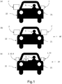
- Fig.1 shows a schematic view of vehicles 20, 20' with rear view assemblies 1, 1', 2, 2' on passenger side 22 and driver side 21 (a) with different individual minimum sizes for driver and passenger sides 21, 22, (b) with common size according to prior art, and (c) with minimized sizes according to the present invention.
- the driver side 21 is indicated by the driver 5.
- the vehicle according to figure 1a comprises first and second rear view assemblies 1, 2' of different but minimized sizes, where the first rear view assembly 1 has a smaller size than the second rear view assembly 2' due to the rhombus of the field of view according to regulation 46 being larger for the passenger side 22 than for the driver side 21.
- Figure 1b shows a vehicle 20' according to prior art, where the sizes of the rear view assemblies 1' and 2' are the same but dictated by the larger rhombus for the required field of view FOV-22 on the passenger side 22.
- Figure 1c shows a vehicle 20 according to the present invention comprising a set of rear view assemblies 10 with first and second rear view assemblies 1, 2, where a first head assembly 1b of the first rear view assembly 1 has a minimum size still fulfilling the legal requirements for provided a mirror-based field of view FOV-21 on the driver side 21, and where a second head assembly 2b of the second rear view assembly 2 has the same minimum size as the first head assembly 1b of the first rear view assembly 1, where a vision system 3 provides an image of the traffic conditions behind on the passenger side 22 displayed on a display 32 connected to the second rear view assembly 2 with a field of view adapted to meet the legal requirements for the mirror-based field of view FOV-22 on the passenger side 21 regardless on the reduced size of the second head assembly 2b of the second rear view assembly 2.
- the image might be recorded by a camera as the vision sensor 31 (see figure 3 ).
- the first and/or the second rear view assembly 1, 2 may comprise further accessories 6 to be utilized separately to the vision sensor 31.
- the first and second rear view assemblies 1, 2 may also be head-mover assemblies with mirror elements 4 fixed to a housing of the first and second head assemblies 1b, 2b.
- Fig.2 shows the field of view rhombus according to regulation 46 as an example for the first rear view assembly 1 on the driver side 21 (a) according to prior art, and (b) according to the present invention.
- the rear view assembly 1 comprises a first base assembly 1a, where the head assembly 1b is mounted to.
- the base assembly 1a is mounted to the vehicle as indicated by the protrusions shown at the lower end of the base assembly 1a.
- Figure 2a shows an existing common rear view assembly, here as a first rear view assembly 1' for the driver side 21.
- the mirror element 4 here a glass mirror, has a glass size fulfilling both driver and passenger field of view requirements FOV-21, FOV- 22.
- the corresponding rhombus fits into the mirror element 4 as indicated by the dashed lines, the larger one for the field of view FOV-22 for the passenger side 22, the smaller one for the field of view FOV-21 for the driver side 21.
- Figure 2b shows the minimized size of the first head assembly 1b of the first rear view assembly 1 (solid line of the mirror element 4) in comparison to the larger size when trying to also cover the rhombus for the field of view FOV-22 for the passenger side (dashed line of the mirror element 4).
- the first head assembly 1b according to the present invention just covers the rhombus for the field of view FOV-21 for the driver side 21, while the rhombus for the passenger side 22 is partly outside the area of the mirror element 4.
- the same small rear view assembly 2 is used also for the passenger side 22, where the vision sensor 31 and the display 32 record and display the field of view FOV-22 according to the legal requirements separate from the second rear view assembly 2 to be conform with the legal requirements.
- another vision sensor 31 is additionally arranged in the first head assembly 1b wherein the vision sensor 31 is arranged behind the mirror element 4 of the first head assembly 1b to record the traffic conditions through the rear view mirror 4, where the mirror element 4 comprises at least one area 41 being at least semitransparent, where the vision sensor 31 is arranged behind this area 41.
- the first rear view assembly 1 and the arrangement of the vision sensor 31 also applies for the second rear view assembly 2.
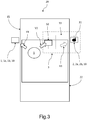
- FIG.3 shows a schematic view of a vehicle with a set of rear view assemblies according to the present invention.
- a set of rear view assemblies 10 is mounted on a vehicle 20, where a first rear view assembly 1 is mounted to the driver side 21 of the vehicle 20 to observe traffic conditions behind on the driver side 21 comprising a first base assembly 1a and a first head assembly 1b mounted on the first base assembly 1a (see figure 2 ), where the first head assembly comprises a mirror element 4 (see figure 2 ) having a minimum size still fulfilling the legal requirements for provided a mirror-based field of view FOV-21 on the driver side 21, and where a second rear view assembly 2 is mounted on the passenger side 22 of the vehicle 20 to observe traffic conditions behind on the passenger side 22 comprising a second base assembly 2a and a second head assembly 2b mounted on the second base assembly 2a, where the second head assembly 2b comprises a mirror element 4 having the same minimum size as one of the first head assembly 1b of the first rear view assembly 1, and a vision system 3 is connected to the second rear view assembly 2 at least
- the driver 5 can observe the traffic behind on the driver side 21 by a driver's view V1 to first rear view assembly 1, the traffic behind on the passenger side 22 by a driver's view V2 to display 32 showing the field of view FOV-22 of second rear view assembly 2 and optionally by a driver's view V3 (dashed arrow) to the second rear view assembly 2.
- the vision sensor 31 can be arranged in the second base assembly 2a or in the second head assembly 2b.
- the vision sensor 31 might be arranged behind the mirror element 4 of the second head assembly 2b to record the traffic conditions through the rear view mirror 4.
- the mirror element 4 may comprise at least one area 41 being at least semitransparent, where the vision sensor 31 is arranged behind this area 41.
- the vision sensor 31 might be a camera.
- the vision sensor 31 and the display 32 and eventually additional components of the vision system 3 not shown here are electrically connected to each other by an electrical connection 33, which might by a bus system insight the vehicle.
- An additional component of the vision system 3 might by a controller to calculate the image content to be displayed based on the signals received from the vision sensor(s) 3.
- the controller may also control accessory installed in the rear view assemblies 1, 2 or being adapted to run a software for correcting the image recorded by the vision sensor 31 to the provided the image in the display 32 with the required field of view.
Landscapes
- Engineering & Computer Science (AREA)
- Multimedia (AREA)
- Mechanical Engineering (AREA)
- Signal Processing (AREA)
- Studio Devices (AREA)
- Rear-View Mirror Devices That Are Mounted On The Exterior Of The Vehicle (AREA)
- Fittings On The Vehicle Exterior For Carrying Loads, And Devices For Holding Or Mounting Articles (AREA)
- Closed-Circuit Television Systems (AREA)
Abstract
Description
- The invention relates to a set of rear view assemblies to be mounted on a vehicle and to a vehicle comprising this set of rear view assembles.
- A rearview device (or rear view mirror assembly) is a type of device generally fulfilling the legal requirements for rear view devices in vehicles, preferably motor vehicles. Therefore such a rear view device provides an image of the rear area, substantially as provided for example in the state-of-the-art using an interior mirror or a camera system and a display device, and of the lateral and backside areas lying diagonal to the sides, substantially as provided for example in the state-of-the-art using external rearview mirrors or camera systems and display devices, the image satisfying at least the legal requirements.
- Such a rearview device within the subgroup of devices for indirect view and as such the tasks, aims and the solutions described in this invention can also be used for indirect view devices. Examples are images and views of objects which are not in the field of view of the driver, i.e. the directions opposing, left, right, below and above of the viewing direction, but also the view along the direction of the viewing direction of the driver and/or any combinations of the directions can be comprised. The view of the driver can be insufficient in particular also in the viewing direction, for example the view can be obstructed by vehicle parts of the vehicle itself, such as for example parts of the vehicle body, in particular the A-pillar, the roof construction and/or the engine hood, and the view can be obstructed by other vehicles and/or objects outside of the vehicle, obstructing the view in such a way that the driver can perceive the situation not completely satisfyingly or only incompletely. Additionally it is possible that the driver is not able to perceive the situation in or beside the viewing direction in such a way to allow him to control the vehicle according to the present situation. Therefore a rearview device can be adapted to reprocess the information according to the abilities of the driver to allow for a best possible perception of the situation.
- Different functions and devices can be incorporated into and/or controlled with the help of rearview devices, comprising especially also cameras.
- Especially useful are functions and devices to enhance, extend and/or sustain the functionality of the rearview device during normal or extreme conditions. This can comprise heating and/or cooling means, cleaning means such as wipers, liquid and/or gaseous sprays, actuator means for moving the rearview device or parts of it, such as for example a display, a camera system and/or parts of a camera system, comprising for example lenses, filters, light sources, adaptive optics like deformable mirrors, sensors and/or mirrors, and/or actuator means for inducing movement of other objects, for example parts of the vehicle and/or objects surrounding the vehicle. Furthermore it can comprise linear tracks and/or rotating wheels, like for example a filter wheel, for exchanging optical elements, comprising for example lenses, mirrors, light sources, sensors, adaptive optics like deformable mirrors and/or filters.
- Prominent examples for functions and devices incorporated into and/or controlled with the help of rearview devices comprise also illumination devices, for example any kind of light module like an external light module, an internal light module, a front light, a back light, a fog light, a brake light, an acceleration light, a turn signal, a logo lamp, a front area illumination light, a ground illumination light, a puddle light, a flash light, a navigation light, a position light, an emergency light, a spotlight, a green light, a red light, a warning light, a turn signal light module, an approach light, a search light, an information light, a display and/or any combination thereof.
- Further examples for functions and devices incorporated into and/or controlled with the help of rearview devices can comprise for example a tiredness detection system, a microsleep detection system, a distance and/or velocity determination system, for example a LIDAR (Light detection and ranging) system, a blind spot indicator system, a lane change assistant system, a navigation assistant system, a tracking assistant system, a human-machine interaction system, a machine-machine interaction system, an emergency and precaution assistant system, like an accident avoiding assistant system, a counter-measures assistant system, a brake assistant system, a steering assistant system, an acceleration assistant system, an escape assistant system, comprising for example an ejection seat system, a direction indicator, a blind spot indicator, an approach system, a strong braking system, an emergency braking system, a charging status indicator, a vehicle mode system, comprising for example a sports mode system, an economy mode system, an autonomous drive mode system, a sleep mode system and an anti-theft system, a vehicle locked indicator system, a vehicle stolen indicator, a warning signal system, a temperature indicator system, a weather indicator system, a traffic light signal system, a fuel status system and/or any combination thereof.
- An example for a rearview device comprising an illumination device fulfilling the brake light functions is disclosed in German patent application No.
102012108488, filed on September 11, 2012 for REARVIEW ASSEMBLY FOR MOTOR VEHICLE and hereby incorporated herein by reference. A light guidance unit for an illumination device used in a back vision system is disclosed in German patent application No.102012104529, filed on May 25, 2012 for LIGHT GUIDANCE UNIT which is hereby incorporated herein by reference. An illumination device for a rearview device is disclosed in German patent application No.102012107833, filed on August 24, 2012 for ILLUMINATION DEVICE AND REARVIEW DEVICE which is hereby incorporated herein by reference. A lighting device for a back-vision unit is disclosed in German patent application No.102012107834, filed on August 24, 2012 for LIGHTING DEVICE AND BACK-VISION UNIT which is hereby incorporated herein by reference. A housing and display device of a rearview device is disclosed in European patent No.2738043, filed on December 3, 2012 for HOUSING AND DISPLAY DEVICE which is hereby incorporated herein by reference. An optical light guide for a vehicle lighting unit is disclosed in European patent No.2947378, filed on May 22, 2014 for OPTICAL LIGHT GUIDE FOR A VEHICLE LIGHTING UNIT which is hereby incorporated herein by reference. A display device of a rearview device of a vehicle is disclosed in International patent application No.2015/173695, filed on May 7, 2015 for DISPLAY DEVICE, REAR VIEW DEVICE AND MOTOR VEHICLE and claiming priority from European patent application No.2944866, filed on May 12, 2014 for OPTICAL UNIT, DISPLAY DEVICE, REAR VIEW DEVICE AND MOTOR VEHICLE INCLUDING THE SAME which are all hereby incorporated herein by reference. Further a light guiding device for an illumination device, in particular for a motor vehicle or a display device, in a rearview device of a motor vehicle is disclosed in European patent application No.3045944, filed on January 19, 2015 for LIGHT GUIDING DEVICE which is hereby incorporated herein by reference. Still further a light guiding device for an illumination device, especially for a motor vehicle or an indicator device in a rearview device of a motor vehicle is disclosed inU.S. patent application No. 15/228,566, filed on August 4, 2016 U.S. patent application No. 15/000,733, filed on January 19, 2016 for LIGHT GUIDING DEVICE which are all hereby incorporated herein by reference. In addition, an illumination device, particularly for a rear-view device of a motor vehicle and a method for producing the same are disclosed in International patent application No.2016/147154, filed on March 18, 2016 for ILLUMINATION DEVICE AND METHOD FOR PRODUCING AN ILLUMINATION DEVICE and claiming priority from German patent application No.102015104163, filed on March 19, 2015 for ILLUMINATION DEVICE AND METHOD FOR PRODUCING AN ILLUMINATION DEVICE which are all hereby incorporated herein by reference. An improved rear-view device for a motor vehicle which includes an electronic device is disclosed inU.S. patent application No. 15/256,532, filed on September 3, 2016 3139711, filed on September 3, 2015 for ELECTRONIC DEVICE AND REAR VIEW DEVICE which are all hereby incorporated herein by reference. A lighting device for a rearview device or a footwell device of a vehicle, comprising at least one luminous means is disclosed in German patent application No.102015115555, filed on September 9, 2015 for ILLUMINATION DEVICE, REAR VIEW DEVICE, FOOTWELL DEVICE AND VEHICLE which is hereby incorporated herein by reference. A light module for a light assembly of an exterior rear view device is disclosed in European patent application No.3138734, filed on September 3, 2015 for LIGHT MODULE, LIGHT ASSEMBLY AND REAR VIEW DEVICE FOR A VEHICLE which is hereby incorporated herein by reference. A lighting device for a vehicle component, in particular for a rearview device of a motor vehicle, comprising a logo lamp and a deflection mirror are disclosed in European patent application No.3144183, filed on September 13, 2016 for LIGHTING DEVICE, VEHICLE COMPONENT AND VEHICLE and claiming priority from German utility patent application No.202015104894, filed on September 15, 2015 for LIGHTING DEVICE, VEHICLE COMPONENT AND VEHICLE which are all hereby incorporated herein by reference. A display device for a motor vehicle and method for operating such a display device is disclosed in the European patent No.2 830 305 B1, filed July 24, 2013 for DISPLAY DEVICE FOR A MOTOR VEHICLE AND METHOD FOR OPERATING SUCH A DISPLAY DEVICE, which is hereby incorporated herein by reference. - The
European patent EP 1 326 764 B1 describes a mirror system comprising a mirror support portion for supporting a mirror glass, where a portion forming part of the outside show surface of the assembled mirror continuous with an outer surface of a mirror cover interchangeably attached to the support portion, which is hereby incorporated herein by reference. TheEuropean patent EP 2 253 510 B1 describes a rear view mirror assembly with a least two parts out of the group of part as: mirror frame, mirror base, mirror housing, mirror bezel, mirror glass, mirror lighting means, actuator, that must be connected during assembly process with at least one retention latch. This retention latch comprises a circular hood and a rectangular arm formed in a first part and to be inserted into an opening and shifted along a slot in a second part, which is hereby incorporated herein by reference. - A camera module can comprise in particular a plurality of different optical elements, comprising a.o. a variety of sensors and light sources, as well as housing parts.
- The housing of a camera module can be made out of plastic, metal, glass, any other suitable material and/or any combinations thereof and can be used in combination with the techniques described below to change or modify the properties of the material or the material surface. Housings are for example described in German patent application No.
102016108247.3, filed on May 3, 2016 for CLEANING SYSTEM FOR A CAMERA andU.S. patent application No. 15/281,780, filed September 30, 2016 - The camera can comprise for example CCD or CMOS or light field sensors, as for example described in German patent application No.
102011053999, filed September 28, 2011 for DETECTION SYSTEM FOR OPTICAL DETECTION OF OBJECT AND/OR REGION OF SPACE FOR DRIVER ASSISTANCE AND/OR DISPLAY SYSTEMS OF MOTOR VEHICLE, HAS OPTICAL SENSOR ARRANGED AS LIGHT FIELD SENSOR FOR DETECTION andU.S. patent application No. 09/771,140, filed on January 26, 2001 U.S. patent No. 6,703,925 , which are all hereby incorporated herein by reference. Also an area of the sensor can be reserved for different purposes, for example to detect a test beam, as described inU.S. patent No. 8,031,224, filed on September 9, 2014 for CAMERA SYSTEM, METHOD FOR OPERATION OF A CAMERA SYSTEM AND SENSOR DEVICE OF A CAMERA SYSTEM, which is hereby incorporated herein by reference. - The optical elements can be molded or formed from any type of glass or any other suitable material. Glass is here used in the meaning of a non-crystalline amorphous solid showing a glass transition when heated towards the liquid state. It comprises for example the group of polymeric glasses, metallic glasses, silica glasses, but any other suitable material showing the glass transition can also be used. The glass can be either in a flat, wedge, rectangular, cylindrical, spherical, conical, elliptical, and/or circular shape, as described for example in German patent application No.
102016108247.3 , and German patent application No.102011103200, filed on May 31, 2011 for LIGHT WINDOW FOR USE AS LIGHT CONDUCTOR FOR TURN INDICATOR IN OUTSIDE MIRROR ARRANGEMENT OF VEHICLE, HAS UNCOUPLING STRUCTURES AT CERTAIN LOCATION OF WINDOW, AND OPTICAL FILM WITH MOLDED COATING AND PROVIDED WITH UNCOUPLING STRUCTURES, which are all hereby incorporated herein by reference, or have a shape according to different needs or lens types. As non-limiting examples camera modules can be equipped with lenses, like a wide-angle or fish-eye lens suitable to provide peripheral images, as described inU.S. patent application No. 15/281,780 , andU.S. patent application No. 13/090,127, filed on April 19, 2011 U.S. patent No. 9,238,434 102011053999, filed September 28, 2011 for DETECTION SYSTEM FOR OPTICAL DETECTION OF OBJECT AND/OR REGION OF SPACE FOR DRIVER ASSISTANCE AND/OR DISPLAY SYSTEMS OF MOTOR VEHICLE, HAS OPTICAL SENSOR ARRANGED AS LIGHT FIELD SENSOR FOR DETECTION, and a TIR (total internal reflection) lens as described inU.S. patent No. 8,740,427, filed September 8, 2010 for OPTIMAL LIGHT COUPLING FOR REAR VIEW DEVICES, which are all hereby incorporated herein by reference. Another type of optical elements know to be used in camera modules are optical fibers, especially in form of fiber bundles and preferably in form of fiber bundles having an optical head, as described for example inU.S. patent application No. 09/771,140 . Different methods can be used to produce such optical elements, for example as described inU.S. patent 8,460,060, filed on January 30, 2009 for METHOD FOR CREATING A COMPLEX SURFACE ON A SUBSTRATE OF GLASS, which is hereby incorporated herein by reference. - The optical elements can be transparent as described for example in
U.S. patent No. 8,031,224 , German patent application No.102016108247.3 , andU.S. patent application No. 13/242,829, filed September 23, 2011 U.S. patent application No. 09/771,140 andU.S. patent application No. 13/090,127 , which are all hereby incorporated herein by reference. Still further, the optical elements can be completely or partially coated with different type of coatings to realize different effects, such as for example anti-reflective coatings as described inU.S. patent No. 8,031,224 , chromium-based reflective coatings as described inU.S. patent No. 9,181,616, filed on January 24, 2012 U.S. patent application No. 14/936,024, filed on Nov. 9, 2015 U.S. patent application No. 15/124,310, filed on Feb. 20, 2015 102016108247.3 , which is hereby incorporated herein by reference. The optical elements can have uncoupling structures at certain locations of the optical elements, and an optical film, for example an extrusion film, and a molded coating can be applied as described in German patent application No.102011103200 , which is hereby incorporated herein by reference. A coating to spectrally and stress control is described inU.S. patent application No. 15/124,310 , which is hereby incorporated herein by reference. Different filters can be integrated into the optical elements such as for example gray filters or polarization filters, described inU.S. patent application No. 14/809,509, filed July 27, 2015 - Electrochromic substrates, polymer electrolytes and other charge conducting medias may be used for the optical elements based on the descriptions of European patent application No.
08103179.1, filed on March 31, 2008 for PROCESS FOR PRODUCING ELECTROCHROMIC SUBSTRATES AND ELECTROCHROMIC ARTICLES MADE THEREFROM, European patent No.2202826, filed on December 23, 2008 for POLYMER ELECTROLYTES AND DEVICES CONTAINING,U.S. patent No. 7,999,992, filed on January 7, 2005 for CHARGE CONDUCTING MEDIUM_andU.S. patent No. 8,537,451, filed on March 26, 2008 for PROCESSES FOR PRODUCING ELECTROCHROMIC SUBSTRATES AND ELECTROCHROMIC ARTICLES MADE THEREFROM, which are all hereby incorporated herein by reference. - The camera module can also be equipped with apparatuses for light intensity adjustment as described for example in
U.S. patent application No. 14/809,509 and light level intensifier tubes as described inU.S. patent application No. 09/771,140 , which are all hereby incorporated herein by reference. The electrochromic substrates and devices used in European patent application No.08103179.1 2202826 ,U.S. patent No. 7,999,992 andU.S. patent No. 8,537,451 , which are all hereby incorporated herein by reference, can also be used for this purpose as well as a transflector to transmit or reflect light based on a corresponding input signal, as described in German patent application No.102016106126.3, filed on April 4, 2016 for IMAGING SYSTEM, which is hereby incorporated herein by reference. - The camera module or a cover adapted to the camera module can be moved using different actuators, drives and/or a flexible track, as for example described in German application No.
102016108247.3 andU.S. patent application No. 15/281,780 , which are all hereby incorporated herein by reference. An actuator device for a rearview device of a motor vehicle comprising at least one retaining element, an adjusting element, at least one driving means comprising at least one shape-memory element, and at least one heat-conducting means is described inU.S. patent application No. 15/165,417, filed May 26, 2016 3 098 444 B1, filed on May 29, 2015 , for ACTUATOR FOR A REAR VIEWING DEVICE OF AN AUTOMOBILE, which are all hereby incorporated herein by reference. An adjustment unit for a rear view device for a vehicle, with a pivot, with a carrier mounted moveable, in particular tiltable, to the pivot, with at least one first bending actuator, which has its largest dimension in a first direction, which is adjustable bendable angular or crosswise to the first direction, which is fixed with a first end to a first fastening means and which is fixed with a second end to the carrier, and with at least one second bending actuator, which has its largest dimension in a second direction angular or crosswise to the first direction, which is bendable angular or crosswise to the second direction, which is fixed with a first end to the first fastening means or to a further fastening means and which is fixed with a second end to the carrier, wherein a bending of the first bending actuator and/or of the second bending actuator effects a movement of the carrier, a rear view device with such an adjustment unit and a vehicle with such an adjustment unit and/or such a rear view device are disclosed inU.S. patent application No. 15/153,106 filed May 12, 2016 3 093 195 B1, filed on May 12, 2015 for ADJUSTMENT UNIT, REAR VIEW DEVICE AND VEHICLE, which are all hereby incorporated herein by reference. An adjustable rearview device for a motor vehicle including a mirror head, a mirror base and at least one joint device which is arranged between the mirror head and mirror base and comprises at least one elastomeric element and an axis of rotation around which the mirror head can move, particularly rotate or fold relative to the mirror base, from a first functional position, in which the elastomeric element holds the mirror head, into at least one second functional position in which the elastomeric element is stretched or compressed, further having at least one electrical conductor, which extends at least between the mirror base and mirror head and through which electrical energy can be transported wherein the at least one electrical conductor is elastically deformable at least in the direction of its longitudinal dimension, a method for manufacturing such a rearview device and a motor vehicle having such a rearview device are disclosed inU.S. patent application No. 15/152,054, filed on May 11, 2016 15167444.7, filed May 12, 2015 U.S. patent application No. 15 / 252,708, filed August 31, 2016 15183334.0, filed September 1, 2015 - Still further, the camera module can also comprise cleaning elements to clean the optical element facing outwards and being exposed to the environment. The cleaning element can for example comprise wipers, brushes, lips, nozzles, fans and similar elements as are described in European patent application No.
14165197.6, filed April 17, 2014 U.S. patent application No. 15/281,780 , German patent application No.102016108247.3 , European patent application No.13163677.1, filed April 15, 2013 15173201.3, filed June 22, 2015 for LENS CLEANING WITH FLEXIBLE ACTUATOR and European patent No.1673260, filed on October 14, 2003 for CLEANING DEVICE which are all hereby incorporated herein by reference. The cleaning devices are not limited in composition, and may for example comprise any fabric, elastomeric, sponge, brush, or combination of these. Special wiper elements comprising wiper arms, wiper blades, wiping cloth, wiping tissue and combinations thereof are described in European patent application No.14165197.6 130164250.6 , filed April 18, 2013 14165197.6 - Different methods may be used to detect dirt or other obscurations preventing or reducing the functioning of the camera module, such as described in
U.S. patent No. 8,395,514, filed on June 24, 2008 for OPTICAL SYSTEM AND METHOD FOR DETECTING OPTICAL SYSTEM OBSCURATION IN A VEHICLE, European patent No.1328141 , filed on January 12, for ASSEMBLY HAVING A CONDUCTOR FROM FLEXIBLE MATERIAL AND METHOD FOR MANUFACTURING SUCH AN ASSEMBLY, andU.S. patent No. 8,031,224 , which are all hereby incorporated herein by reference. - Also light sources can be installed or integrated into the camera module to increase the visibility of surrounding objects, measure distances and directions and detect dirt, such as described in
U.S. patent No. 8,031,224 ,U.S. patent application No. 62/470,658, filed on March 13, 2017 U.S. patent application No. 09/771,140 , which are all hereby incorporated herein by reference. - Different heating means, like heating coils, heating devices integrated into the lens holder or the bezel, or other heating elements can be used to impede condensation and icing at the surface of optical elements, as for example described in German patent application No.
102016108247.3 ,U.S. patent application No. 62/470,658 102016107545.0, filed on April 22, 2016 for HEATING DEVICE FOR A CAMERA LENS, which are all hereby incorporated herein by reference. - A watertight seal against weather effects, as well as against the influence of washing processes with detergents, solvents and high pressure cleaners can be used on the housing of the camera module as described in
U.S. patent application No. 13/090,127 , which is hereby incorporated herein by reference. An exterior review device for a motor vehicle and a sealing element for sealing an aperture of a wall element of an exterior rearview device is disclosed in the German patent No.10 2012 107 680 B3, filed on August 21, 2012 for AUSSENRÜCKBLICKANORDNUNG FÜR EIN KRAFTFAHRZEUG UND DICHTUNGSVORRICHTUNG, which is hereby incorporated herein by reference. A sealing device for a rear view device, such as an inside or outside mirror or camera, of a motor vehicle, which can be arranged between a foot part and a head part that can be rotated relative to the foot part from a normal position into at least one fold-in position about an axis of rotation, having at least one sealing means, which can be or is fixed to the foot part or the head part and which can be or is arranged in a sealing arrangement in which it is in contact with the foot part and the head part and closes a gap existing between the foot part and the head part and in addition a rear view device having such a sealing device are disclosed inU.S. patent application No. 15/314,390, filed May 8, 2015 2 949 512 B1, filed May 27, 2014 for SEALING DEVICE, REAR VIEWING DEVICE AND MOTOR VEHICLE, which are all hereby incorporated herein by reference. - A rear view element folding device for a motor vehicle for approaching at least one pivot position of an element housing relative to an element foot that can be mounted on the motor vehicle, and for locking or unlocking at least one resting position of the element housing relative to the element foot as well as a method for triggering such a rear view element folding device are disclosed in
U.S. patent application No. 15 / 349,657, filed on November 11, 2016 16197212.0, filed on November 4, 2016 20 2015 106 118.8 filed on November 12, 2015 , which are all hereby incorporated herein by reference. - Additionally or alternatively, the housing can be made of a body comprising plastic and conductive material, wherein the conductive material is dispersed in the plastic material to form a conductive mass to allow a power source, preferably a DC voltage source, to connect via at least two electrodes to the body and heat the body accordingly, as described in German patent application No.
102016107545.0 , which is hereby incorporated herein by reference.
A conductor track can be embedded within plastic parts of the camera module as described in European patent No.1328141 andU.S. patent No. 7,083,311, filed on January 12, 2002 for CONDUCTOR OF FLEXIBLE MATERIAL, COMPONENT COMPRISING SUCH FLEXIBLE CONDUCTOR, AND METHOD OF MANUFACTURING SUCH CONDUCTOR, which are all hereby incorporated herein by reference. - An electronic circuit board unit for an electronic module installed in a vehicle rear view device, with an, essentially plane, base plate, comprising at least one driver circuit, with a first connector for directly or indirectly connecting the base plate with at least one power supply, with at least one, essentially plane, printed circuit board, which is disposable or disposed parallel, angular or cross to the base plate and which is spaced to the base plate, in particular in a manner having no direct contact to the base plate, with at least one plug connection for electronically and physically connecting between the printed circuit board and the base plate, and with at least one first receiver for mounting an electronic consumer unit of the electronic module and being attachable or attached to the base plate or to one of the at least one printed circuit board, wherein at least one second connector attachable or attached to the base plate or to the at least one printed circuit board for connecting at least one further electronic consumer unit of the electronic module to the driver circuit of the base plate, such that either n printed circuit boards and n+1 of electronic consumer units are comprised, with n being an integer number of 1 and above, or a plurality of printed circuit boards is provided, with each circuit board comprising at least one first receiver and at least one second connector is disclosed in
U.S. patent application No. 15 / 256,537, filed September 3, 2016 15183741.6, filed September 3, 2015 - The camera module can comprise a power harvesting system as described for example in European patent application No.
09171683.7, filed on Sept. 29, 2009 - A fault detection system for electric consumers as described in
U.S. patent No. 8,487,633 filed on January 14, 2010 for FAULT DETECTION OF ELECTRIC CONSUMERS IN MOTOR VEHICLES, which is hereby incorporated herein by reference, can be used to detect failure of the camera module. - Different types of fixings can be used to fix the camera module to the vehicle or other components, such as for example the snap-fit connection described in European patent No.
2233360, filed on March 27, 2009 for SNAP FIT CONNECTION IN A REAR VIEW MIRROR, which is hereby incorporated herein by reference. - Different control means and analyzing devices can be used, such as the computation units described in
U.S. patent application No. 13/090,127 , German patent application No.102016106126.3 , German patent application No.102011053999 , European patent No.2146325, filed on July 16, 2008 for RECORDING DEVICE FOR RECEIVING, PROCESSING AND STORING IMAGE FILES IN A VEHICLE AND METHOD, andU.S. patent No. 8,849,104, filed on July 16, 2008 for RECORDING DEVICE AND METHOD FOR CAPTURING AND PROCESSING IMAGE DATA IN A VEHICLE, which are all hereby incorporated herein by reference. In addition, HDR (high dynamical range) technology can be used according toU.S. patent application No. 14/830,406, filed on Aug. 19, 2015 US 20150358590 , which is hereby incorporated herein by reference. A method for processing input image data by an image processing device, to achieve a desired visual effect within the output image, wherein input image data are stored within an input memory device and the input image data are transferred based on data of a lookup table into respective output image data stored within an output memory device, the lookup table being generated based on at least one data remapping function is disclosed inU.S. patent application No. 14/891,548, filed on May 13, 2014 13168085.2, filed on May 16, 2013 - Rear view mirror assemblies have to fulfill the legal requirements for rear view mirror assemblies in vehicles, preferably motor vehicles, with respect to the size of the provided field of view. The rear view mirror assembly on the driver side could be smaller than on the passenger side due to the smaller distance between driver and rear view mirror on the driver side to fulfill the legal requirements according to regulation 46 with respect to the minimum field of view to be provided. However, the external appearance of a vehicle would suffer if the exterior mirrors were to be asymmetrically sized, which is why the same size exterior mirrors are used in all vehicle types, whereby the size of the driver's mirror is determined by the legally required larger exterior mirror on the passenger side and is therefore oversized. Exterior mirrors that are larger than necessary have a negative effect on the air resistance, noise and the weight of the vehicle and thus on its performance.
-
DE 10 2008 035 429 A1 provides a monitoring device for monitoring rearward traffic conditions in front and rear of the vehicle, where the device comprises an image detection unit, which is integrated into one of longitudinal sides of the vehicle. The image detection unit replaces the exterior rear view mirrors on driver and passenger side and is connected with a driver assistance system by a data processing unit, where the driver assistance system is controllable based on data determined from the traffic conditions. The image detection unit is connected with an output unit in the interior of the vehicle by a data processing unit. The disadvantage of such system is that in case of a malfunction of the monitoring device the driver as no possibility to observe the traffic behind the vehicle from his common driver position. - It would be desirable to have a set of exterior mirrors available which would overcome the disadvantages of the state of the art, in particular a set of exterior mirrors having a positive effect on the performance of the vehicle but still providing a backup system for observing the traffic conditions behind.
- It is an object of the invention to provide a set of exterior mirrors having a positive effect on the performance of the vehicle but still providing a backup system for observing the traffic conditions behind.
- This problem is solved by a set of rear view assemblies for a vehicle comprising:
- a first rear view assembly to be mounted to a driver side of the vehicle to observe traffic conditions behind on the driver side, comprising a first base assembly and a first head assembly mounted on the first base assembly, where the first head assembly comprises a mirror element having a minimum size still fulfilling the legal requirements for provided a mirror-based field of view on the driver side, and
- a second rear view assembly to be mounted on a passenger side of the vehicle to observe traffic conditions behind on the passenger side, comprising a second base assembly and a second head assembly mounted on the second base assembly, where the second head assembly comprises a mirror element having the same minimum size as the one of the first head assembly of the first rear view assembly,
- a vision system at least comprising a vision sensor and a display, where the vision sensor is arranged in the second rear view assembly to record an image of the traffic conditions behind on the passenger side to be displayed to a driver by the display with a field of view adapted to meet the legal requirements for the mirror-based field of view on the passenger side regardless on the reduced size of the second head assembly of the second rear view assembly.
- The driver and passenger field of view requirements for passenger vehicles determine mirror glass height and mirror proportions, which defines the corresponding dimensions of the head assembly carrying the mirror element. The field of view which must be present on a rear view mirror is given by a so-called rhombus (see also
figure 2 , where the rhombus is denoted as FOV-21 and FOV-22) according to the regulation 46 of the Economic Commission for Europe of the United Nations (UNECE) - Uniform provisions concerning the approval of devices for indirect vision and of motor vehicles with regard to the installation of these devices - specifying the vehicle requirements with respect to safety, among other the minimum height and width of the rear view mirrors of vehicles. The field of view (rhombus) on the passenger side is larger than the field of view on the driver side, since the distance between driver and rear view mirror is larger when viewing the rear view mirror on the passenger side. Since the size of rear view mirrors is desired as to be symmetrical for driver and passenger side, the passenger rhombus dictates the size of the rear view mirror also on the driver side. The present inventions still fulfills the demand of providing symmetrical rear view assemblies for driver and passenger sides, but applies a vision sensor on the passenger side to get another degree of freedom with respect to the size of the rear view assemblies. When displaying the field of view on the passenger side via a display to the driver, the larger rhombus of the passenger side no longer dictates the size of the rear view assembly on the driver side. Now the rear view assembly on the driver side can be reduced to a size adapted to the smaller rhombus for the driver side resulting in a much smaller rear view assembly, especially in a much smaller first head assembly only having to carry a much smaller mirror element. The field of view on the passenger side is recorded by a vision sensor and displayed on a display, where the image content covers the traffic conditions behind with the legally required field of view, since the image size can be adapted electronically. The vision sensor at least on the passenger side provides additional functionality to the rear view assembly at least on the passenger side. Therefore the rear view assemblies can be minimized to the minimum size required for the driver side resulting in a much smaller set of rear view assemblies to be mounted on vehicles. Such set of rear view assemblies according to the present invention improves the air resistance, noise and the weight of the vehicle and thus on its performance while maintaining a backup solution to be able to observer the traffic conditions behind the vehicle even in case of a malfunction of the vision system providing a failure-safe sensor condition, because the rear view assemblies still comprise mirror elements providing a field of view of the traffic behind, which is somewhat smaller on the passenger side, but still observable from a common driver position without any need for the driver to turn around and look to the back of his vehicle. - The vision system may comprise further components in addition to the vision sensor and the display. Preferably, the vision system includes a data processing unit for image processing. The vision system can also be connected to a driver assistance system, which determines a traffic situation from the collected data and, if necessary, controls warning systems in the vehicle, some of which can also be accommodated in the rearview mirror assembly as accessories.
- The display might be a LCD or OLED screen or other screens. The display can be mounted at any position in the passenger compartment that is suitable for the driver, for example in or on the dashboard or on the inside of the passenger front door, for example in the area of the A-pillar.
- The vision sensor might be any sensor suitable to record a scenery, here the traffic condition behind or on the side of the vehicle (passenger side, eventually also driver side). The vision sensor can be connected to the vehicle's electrical system via any bus system or via a separate cable connection.
- The set of rear view assemblies according to the present invention provides a positive effect on the performance of the vehicle but is still operational as a backup system for observing the traffic conditions behind.
- In an embodiment the vision sensor is arranged in the second base assembly or in the second head assembly. The vision sensor may be attached to the frame structure of the base assembly or head assembly. Both base and head assemblies provide enough space to integrate the vision sensor in it.
- In another embodiment the vision sensor is arranged behind the mirror element of the second head assembly to record the traffic conditions through the rear view mirror. Here the vision sensor is encapsulated by the housing of the second head assembly, where the mirror element is mounted to. The encapsulation prevents the vision sensor from environmental influences keeping the vision sensor clean and operational at any whether conditions.
- In another embodiment the mirror element comprises at least one area being at least semitransparent, where the vision sensor is arranged behind this area. A semitransparent area within the line of view of the vision sensor enables the vision sensor to observe and record the traffic behind in images having good image quality.
- In another embodiment another vision sensor is additionally arranged in the first base assembly or in the first head assembly. This allows to further reduce the size of the rear view assemblies, because in this case, the size of the mirror element in the first head assembly of the driver side is also not dictated anymore by the rhombus size for the driver side according to regulation 46. Here the first head or base assembly only has to provide enough space to house the vision sensor.
- In another embodiment the vision sensor is arranged behind the mirror element of the first head assembly to record the traffic conditions through the rear view mirror for the same reasons as described for the second rear view assembly.
- In another embodiment the mirror element comprises at least one area being at least semitransparent, where the vision sensor is arranged behind this area for the same reasons as described for the second rear view assembly.
- In another embodiment the vision sensor is a camera. For example, a video camera with a wide-angle lens can be used, whereby the camera in one version can include a super-wide-angle lens or a fisheye lens. Small cameras fitting into base or head assemblies are available.
- In another embodiment the vision system is adapted to run a software for correcting the image recorded by the vision sensor to the provided the image with the required field of view in the display. Image correction allows to display an image of the right size comparable to the rhombus for passenger size according to regulation 46. Furthermore different image sensors can be installed, where the displayed images can be processed in a way delivering the same images and qualities regardless the used vision sensor and its current status, e.g. with respect to component life time and/or cleanliness status.
- In another embodiment the first and/or the second rear view assembly comprises further accessories to be utilized separately to the vision sensor, since the space within the rear view assembly is partly unoccupied and may accommodate additional components. Such accessories might by a downward facing camera and/or a sideward facing camera and/or a forward facing camera, a turn signal indicator, a blind spot indicators, a light source or a display, a logo light, a bottom light, a position light, a compass sensor, a tire pressure monitoring system, a passenger air bag status or a garage door opening system or a telematics system, global positioning system (GPS) or cellular phone antenna or the like.
- In another embodiment the first and second rear view assemblies are head-mover assemblies with mirror elements fixed to a housing of the first and second head assemblies. This reduces the number of components required within the head assembly in order to move the rear view assembly to adjust the working position of the rear view assemblies.
- The invention relates further to a vehicle comprising a set of rear view assemblies according to the present invention with first and second rear view assemblies, where a first head assembly of the first rear view assembly has a minimum size still fulfilling the legal requirements for provided a mirror-based field of view on the driver side, and where a second head assembly of the second rear view assembly has the same minimum size as the first head assembly of the first rear view assembly, where a vision system provides an image of the traffic conditions behind on the passenger side with a field of view adapted to meet the legal requirements for the mirror-based field of view on the passenger side regardless on the reduced size of the second head assembly of the second rear view assembly. The vehicle might be any type of vehicles, where rear view assemblies are used.
- The vehicle comprising the set of rear view assemblies according to the present invention have a better performance, e.g. with respect to air resistance, noise and the weight of the vehicle and is still operational with the rear view assemblies itself as a backup system for observing the traffic conditions behind.
- The above listed embodiments can be used individually or in any combination to provide the device and the process in accordance with the invention.
- These and other aspects of the invention are shown in detail in the illustrations as follows.
- Fig.1:
- schematic view of vehicles with rear view assemblies on passenger and driver side (a) with individual minimum sizes for driver and passenger sides, (b) with common size according to prior art, and (c) with minimized sizes according to the present invention;
- Fig.2:
- field of view rhombus according to regulation 46 for the first rear view assembly on the driver side (a) according to prior art, and (b) according to the present invention; and
- Fig.3:
- schematic view of a vehicle with a set of rear view assemblies according to the present invention.
-
Fig.1 shows a schematic view ofvehicles 20, 20' withrear view assemblies passenger side 22 and driver side 21 (a) with different individual minimum sizes for driver andpassenger sides driver side 21 is indicated by thedriver 5. The vehicle according tofigure 1a comprises first and secondrear view assemblies 1, 2' of different but minimized sizes, where the firstrear view assembly 1 has a smaller size than the second rear view assembly 2' due to the rhombus of the field of view according to regulation 46 being larger for thepassenger side 22 than for thedriver side 21.Figure 1b shows a vehicle 20' according to prior art, where the sizes of the rear view assemblies 1' and 2' are the same but dictated by the larger rhombus for the required field of view FOV-22 on thepassenger side 22.Figure 1c shows avehicle 20 according to the present invention comprising a set of rear view assemblies 10 with first and secondrear view assemblies first head assembly 1b of the firstrear view assembly 1 has a minimum size still fulfilling the legal requirements for provided a mirror-based field of view FOV-21 on thedriver side 21, and where a second head assembly 2b of the secondrear view assembly 2 has the same minimum size as thefirst head assembly 1b of the firstrear view assembly 1, where avision system 3 provides an image of the traffic conditions behind on thepassenger side 22 displayed on adisplay 32 connected to the secondrear view assembly 2 with a field of view adapted to meet the legal requirements for the mirror-based field of view FOV-22 on thepassenger side 21 regardless on the reduced size of the second head assembly 2b of the secondrear view assembly 2. The image might be recorded by a camera as the vision sensor 31 (seefigure 3 ). Here the first and/or the secondrear view assembly vision sensor 31. The first and secondrear view assemblies mirror elements 4 fixed to a housing of the first andsecond head assemblies 1b, 2b. -
Fig.2 shows the field of view rhombus according to regulation 46 as an example for the firstrear view assembly 1 on the driver side 21 (a) according to prior art, and (b) according to the present invention. Therear view assembly 1 comprises afirst base assembly 1a, where thehead assembly 1b is mounted to. Thebase assembly 1a is mounted to the vehicle as indicated by the protrusions shown at the lower end of thebase assembly 1a.Figure 2a shows an existing common rear view assembly, here as a first rear view assembly 1' for thedriver side 21. However the rear view assembly for thepassenger side 22 is identical, but only laterally reversed. Themirror element 4, here a glass mirror, has a glass size fulfilling both driver and passenger field of view requirements FOV-21, FOV- 22. The corresponding rhombus fits into themirror element 4 as indicated by the dashed lines, the larger one for the field of view FOV-22 for thepassenger side 22, the smaller one for the field of view FOV-21 for thedriver side 21.Figure 2b shows the minimized size of thefirst head assembly 1b of the first rear view assembly 1 (solid line of the mirror element 4) in comparison to the larger size when trying to also cover the rhombus for the field of view FOV-22 for the passenger side (dashed line of the mirror element 4). Thefirst head assembly 1b according to the present invention just covers the rhombus for the field of view FOV-21 for thedriver side 21, while the rhombus for thepassenger side 22 is partly outside the area of themirror element 4. The same smallrear view assembly 2 is used also for thepassenger side 22, where thevision sensor 31 and thedisplay 32 record and display the field of view FOV-22 according to the legal requirements separate from the secondrear view assembly 2 to be conform with the legal requirements. Infigure 2b anothervision sensor 31 is additionally arranged in thefirst head assembly 1b wherein thevision sensor 31 is arranged behind themirror element 4 of thefirst head assembly 1b to record the traffic conditions through therear view mirror 4, where themirror element 4 comprises at least onearea 41 being at least semitransparent, where thevision sensor 31 is arranged behind thisarea 41. What is shown here for the firstrear view assembly 1 and the arrangement of thevision sensor 31 also applies for the secondrear view assembly 2. -
Fig.3 shows a schematic view of a vehicle with a set of rear view assemblies according to the present invention. A set of rear view assemblies 10 is mounted on a vehicle 20, where a first rear view assembly 1 is mounted to the driver side 21 of the vehicle 20 to observe traffic conditions behind on the driver side 21 comprising a first base assembly 1a and a first head assembly 1b mounted on the first base assembly 1a (seefigure 2 ), where the first head assembly comprises a mirror element 4 (seefigure 2 ) having a minimum size still fulfilling the legal requirements for provided a mirror-based field of view FOV-21 on the driver side 21, and where a second rear view assembly 2 is mounted on the passenger side 22 of the vehicle 20 to observe traffic conditions behind on the passenger side 22 comprising a second base assembly 2a and a second head assembly 2b mounted on the second base assembly 2a, where the second head assembly 2b comprises a mirror element 4 having the same minimum size as one of the first head assembly 1b of the first rear view assembly 1, and a vision system 3 is connected to the second rear view assembly 2 at least comprising a vision sensor 31 and a display 32, where the vision sensor 31 is arranged in the second rear view assembly 2 to record an image of the traffic conditions behind on the passenger side 22 to be displayed to the driver 5 by the display 32 with a field of view adapted to meet the legal requirements for the mirror-based field of view FOV-22 on the passenger side 21 regardless on the reduced size of the second head assembly 2b of the second rear view assembly 2. Thedriver 5 can observe the traffic behind on thedriver side 21 by a driver's view V1 to firstrear view assembly 1, the traffic behind on thepassenger side 22 by a driver's view V2 to display 32 showing the field of view FOV-22 of secondrear view assembly 2 and optionally by a driver's view V3 (dashed arrow) to the secondrear view assembly 2. Thevision sensor 31 can be arranged in the second base assembly 2a or in the second head assembly 2b. Thevision sensor 31 might be arranged behind themirror element 4 of the second head assembly 2b to record the traffic conditions through therear view mirror 4. Themirror element 4 may comprise at least onearea 41 being at least semitransparent, where thevision sensor 31 is arranged behind thisarea 41. Thevision sensor 31 might be a camera. Thevision sensor 31 and thedisplay 32 and eventually additional components of thevision system 3 not shown here are electrically connected to each other by anelectrical connection 33, which might by a bus system insight the vehicle. An additional component of thevision system 3 might by a controller to calculate the image content to be displayed based on the signals received from the vision sensor(s) 3. The controller may also control accessory installed in therear view assemblies vision sensor 31 to the provided the image in thedisplay 32 with the required field of view. - The embodiments shown here are only examples of the present invention and must therefore not be understood as restrictive. Alternative embodiments considered by the skilled person are equally covered by the scope of protection of the present invention.
-
- 1
- first rear view assembly according to the invention
- 1'
- first rear view assembly according to prior art
- 1a
- base assembly of the first rear view assembly
- 1b
- head assembly of the first rear view assembly
- 2
- second rear view assembly according to the invention
- 2'
- second rear view assembly according to prior art
- 2a
- base assembly of the second rear view assembly
- 2b
- head assembly of the second rear view assembly
- 3
- vision system
- 31
- vision sensor, e.g. a camera
- 32
- display
- 33
- electrical connection
- 4
- mirror element
- 41
- at least semitransparent area of the rear view mirror
- 5
- driver
- 6
- accessory
- 10
- set of rear view assemblies according to the invention
- 20
- vehicle according to the invention
- 20'
- vehicle according to prior art
- 21
- driver side
- 22
- passenger side
- FOV-21
- field of view of first rear view assembly (driver side)
- FOV-22
- field of view of second rear view assembly (passenger side)
- V1
- driver's view to the first rear view assembly
- V2
- driver's view to the display showing field of view of second rear view assembly
- V3
- driver's view to the second rear view assembly
Claims (12)
- A set of rear view assemblies (10) for a vehicle (20) comprising:- a first rear view assembly (1) to be mounted to a driver side (21) of the vehicle (20) to observe traffic conditions behind on the driver side (21), comprising a first base assembly (1a) and a first head assembly (1b) mounted on the first base assembly (1a), where the first head assembly comprises a mirror element (4) having a minimum size still fulfilling the legal requirements for provided a mirror-based field of view (FOV-21) on the driver side (21), and- a second rear view assembly (2) to be mounted on a passenger side (22) of the vehicle (20) to observe traffic conditions behind on the passenger side (22), comprising a second base assembly (2a) and a second head assembly (2b) mounted on the second base assembly (2a), where the second head assembly (2b) comprises a mirror element (4) having the same minimum size as one of the first head assembly (1b) of the first rear view assembly (1),- a vision system (3) at least comprising a vision sensor (31) and a display (32), where the vision sensor (31) is arranged in the second rear view assembly (2) to record an image of the traffic conditions behind on the passenger side (22) to be displayed to a driver (5) by the display (32) with a field of view adapted to meet the legal requirements for the mirror-based field of view (FOV-22) on the passenger side (21) regardless on the reduced size of the second head assembly (2b) of the second rear view assembly (2).
- The set of rear view assemblies (10) as claimed in claim 1, wherein the vision sensor (31) is arranged in the second base assembly (2a) or in the second head assembly (2b).
- The set of rear view assemblies (10) as claimed in claim 2, wherein the vision sensor (31) is arranged behind the mirror element (4) of the second head assembly (2b) to record the traffic conditions through the rear view mirror (4).
- The set of rear view assemblies (10) as claimed in claim 3, where the mirror element (4) comprises at least one area (41) being at least semitransparent, where the vision sensor (31) is arranged behind this area (41).
- The set of rear view assemblies (10) as claimed in one of the preceding claims, wherein another vision sensor (31) is additionally arranged in the first base assembly (1a) or in the first head assembly (1b).
- The set of rear view assemblies (10) as claimed in claim 5, wherein the vision sensor (31) is arranged behind the mirror element (4) of the first head assembly (1b) to record the traffic conditions through the rear view mirror (4).
- The set of rear view assemblies (10) as claimed in claim 6, where the mirror element (4) comprises at least one area (41) being at least semitransparent, where the vision sensor (31) is arranged behind this area (41).
- The set of rear view assemblies (10) as claimed in one of the preceding claims, wherein the vision sensor (31) is a camera.
- The set of rear view assemblies (10) as claimed in in one of the preceding claims, wherein the vision system (3) is adapted to run a software for correcting the image recorded by the vision sensor (31) to the provided the image in the display (32) with the required field of view.
- The set of rear view assemblies (10) as claimed in one of the preceding claims, wherein the first and/or the second rear view assembly (1, 2) comprises further accessories (6) to be utilized separately to the vision sensor (31).
- The set of rear view assemblies (10) as claimed in one of the preceding claims, wherein the first and second rear view assemblies (1, 2) are head-mover assemblies with mirror elements (4) fixed to a housing of the first and second head assemblies (1b, 2b).
- A vehicle (20) comprising a set of rear view assemblies (10) as claimed in one of claims 1 to 10 with first and second rear view assemblies (1, 2), where a first head assembly (1b) of the first rear view assembly (1) has a minimum size still fulfilling the legal requirements for provided a mirror-based field of view (FOV-21) on the driver side (21), and where a second head assembly (2b) of the second rear view assembly (2) has the same minimum size as the first head assembly (1b) of the first rear view assembly (1), where a vision system (3) provides an image of the traffic conditions behind on the passenger side (22) with a field of view adapted to meet the legal requirements for the mirror-based field of view (FOV-22) on the passenger side (21) regardless on the reduced size of the second head assembly (2b) of the second rear view assembly (2).
Priority Applications (12)
| Application Number | Priority Date | Filing Date | Title |
|---|---|---|---|
| EP18198678.7A EP3632748B1 (en) | 2018-10-04 | 2018-10-04 | Rear view assembly and vehicle with such rear view assembly |
| CN201880070556.4A CN111448102B (en) | 2017-11-01 | 2018-10-31 | Exterior rearview equipment and vehicles |
| PCT/EP2018/079886 WO2019086544A1 (en) | 2017-11-01 | 2018-10-31 | External rearview device, external rearview device kit and vehicle |
| EP18795652.9A EP3681761B1 (en) | 2017-11-01 | 2018-10-31 | External rearview device, external rearview device kit and vehicle |
| US16/757,834 US11273764B2 (en) | 2012-01-24 | 2018-10-31 | External rearview device, external rearview device kit and vehicle |
| US17/282,230 US11541811B2 (en) | 2018-10-04 | 2019-10-04 | Set of rear view assemblies and vehicle |
| PCT/EP2019/076937 WO2020070295A1 (en) | 2018-10-04 | 2019-10-04 | Set of rear view assemblies and vehicle |
| EP19782601.9A EP3860879A1 (en) | 2018-10-04 | 2019-10-04 | Set of rear view assemblies and vehicle |
| US17/587,931 US12134350B2 (en) | 2012-01-24 | 2022-01-28 | Rear view device with actuator and gasket sealing head mover |
| US17/680,658 US12122299B2 (en) | 2012-01-24 | 2022-02-25 | External rearview device, external rearview device kit and vehicle |
| US17/939,264 US11890989B2 (en) | 2012-01-24 | 2022-09-07 | External rearview device, external rearview device kit and vehicle |
| US18/832,201 US20250108758A1 (en) | 2012-01-24 | 2023-01-27 | Rear View Device with Actuator and Gasket Sealing Head Mover |
Applications Claiming Priority (1)
| Application Number | Priority Date | Filing Date | Title |
|---|---|---|---|
| EP18198678.7A EP3632748B1 (en) | 2018-10-04 | 2018-10-04 | Rear view assembly and vehicle with such rear view assembly |
Publications (2)
| Publication Number | Publication Date |
|---|---|
| EP3632748A1 true EP3632748A1 (en) | 2020-04-08 |
| EP3632748B1 EP3632748B1 (en) | 2022-05-18 |
Family
ID=63762400
Family Applications (2)
| Application Number | Title | Priority Date | Filing Date |
|---|---|---|---|
| EP18198678.7A Active EP3632748B1 (en) | 2012-01-24 | 2018-10-04 | Rear view assembly and vehicle with such rear view assembly |
| EP19782601.9A Withdrawn EP3860879A1 (en) | 2018-10-04 | 2019-10-04 | Set of rear view assemblies and vehicle |
Family Applications After (1)
| Application Number | Title | Priority Date | Filing Date |
|---|---|---|---|
| EP19782601.9A Withdrawn EP3860879A1 (en) | 2018-10-04 | 2019-10-04 | Set of rear view assemblies and vehicle |
Country Status (3)
| Country | Link |
|---|---|
| US (1) | US11541811B2 (en) |
| EP (2) | EP3632748B1 (en) |
| WO (1) | WO2020070295A1 (en) |
Citations (46)
| Publication number | Priority date | Publication date | Assignee | Title |
|---|---|---|---|---|
| EP1328141A2 (en) | 2002-01-12 | 2003-07-16 | Schefenacker Vision Systems Germany GmbH & Co. KG | Conductor from flexible material, assembly having such a flexible conductor and method for manufacturing such a conductor |
| US6703925B2 (en) | 2000-01-28 | 2004-03-09 | Reitter & Schefenacker Gmbh & Co. Kg | Monitoring device for vehicles, in particular, motor vehicles |
| EP1673260A2 (en) | 2003-10-14 | 2006-06-28 | Schefenacker Vision Systems Germany GmbH & Co. KG | Cleaning device |
| WO2006104317A1 (en) * | 2005-03-29 | 2006-10-05 | Hyuk-Jin Jang | A view guarantee system for vehicle and its displaying method |
| EP1326764B1 (en) | 2000-06-15 | 2007-03-07 | Schefenacker Vision Systems USA Inc. | Mirror with interchangeable appearance covers |
| DE102008035429A1 (en) | 2008-07-30 | 2009-04-09 | Daimler Ag | Vehicle i.e. car, has monitoring device provided for monitoring traffic conditions in front and rear of vehicle, where device comprises image detection unit i.e. camera, which is integrated into one of longitudinal sides of vehicle |
| EP2146325A1 (en) | 2008-07-16 | 2010-01-20 | SMR PATENTS S.à.r.l. | Recording device for receiving and processing image files in a vehicle and method |
| EP2202826A1 (en) | 2008-12-23 | 2010-06-30 | SMR PATENTS S.à.r.l. | Polymer Electrolytes and Devices containing them |
| EP2233360A1 (en) | 2009-03-27 | 2010-09-29 | SMR Patents S.à.r.l. | Snap fit connection in a rear view mirror |
| US7999992B2 (en) | 2005-07-01 | 2011-08-16 | Smr Patents S.A.R.L. | Charge conducting medium |
| US8031224B2 (en) | 2006-09-14 | 2011-10-04 | Smr Patents S.A.R.L. | Camera system, method for operation of a camera system and sensor device of a camera system |
| DE102011103200A1 (en) | 2011-05-31 | 2012-12-06 | SMR Patents S.à.r.l. | Light window for use as light conductor for turn indicator in outside mirror arrangement of vehicle, has uncoupling structures at certain location of window, and optical film with molded coating and provided with uncoupling structures |
| EP2253510B1 (en) | 2009-05-19 | 2013-01-02 | SMR Patents S.à.r.l. | Modular Rear View Mirror and Method to assemble it |
| US8395514B2 (en) | 2008-06-24 | 2013-03-12 | Smr Patents S.A.R.L. | Optical system and method for detecting optical system obscuration in a vehicle |
| DE102011053999A1 (en) | 2011-09-28 | 2013-03-28 | SMR Patents S.à.r.l. | Detection system for optical detection of object and/or region of space for driver assistance and/or display systems of motor vehicle, has optical sensor arranged as light field sensor for detection of direction information of light beam |
| WO2013067082A1 (en) * | 2011-11-01 | 2013-05-10 | Magna Mirrors Of America, Inc. | Vision system with door mounted exterior mirror and display |
| US8460060B2 (en) | 2009-01-30 | 2013-06-11 | Smr Patents S.A.R.L. | Method for creating a complex surface on a substrate of glass |
| US8487633B2 (en) | 2010-01-14 | 2013-07-16 | Smr Patents S.A.R.L. | Fault detection of electric consumers in motor vehicles |
| US8537451B2 (en) | 2008-03-26 | 2013-09-17 | Smr Patents S.A.R.L. | Processes for producing electrochromic substrates and electrochromic articles made therefrom |
| DE102012104529A1 (en) | 2012-05-25 | 2013-11-28 | SMR Patents S.à.r.l. | Light guidance unit for illumination device used in back vision system e.g. wing mirror of motor car, has cover portion that completely covers idle surface of optical effective element arranged against guidance portion surface section |
| DE102012107833A1 (en) | 2012-08-24 | 2014-02-27 | SMR Patents S.à.r.l. | Illumination device for rearview device e.g. exterior mirror, of motor vehicle, has illumination unit comprising lighting unit fixed with fixing unit of sealing unit such that light of lighting unit is coupled to body over coupling area |
| DE102012107834A1 (en) | 2012-08-24 | 2014-02-27 | SMR Patents S.à.r.l. | Lighting device for back-vision unit, such as interior- or exterior mirrors, of motor vehicle, has clamping unit with adjusting unit, with which distance between lighting unit and light coupling area is adjustable |
| DE102012108488A1 (en) | 2012-09-11 | 2014-03-13 | SMR Patents S.à.r.l. | Rearview assembly for motor vehicle, comprises rearview element and illumination unit that designs brake light functions, where rearview element is arranged according to external view mirror element in external area of motor vehicle |
| DE102012107680B3 (en) | 2012-08-21 | 2014-03-20 | SMR Patents S.à.r.l. | Outer review arrangement for installation at driver's side of passenger motor car, has wall element limiting ingress of liquid, and deformable element comprising porous material that partially borders on deformable element |
| JP2014061808A (en) * | 2012-09-21 | 2014-04-10 | Ichikoh Ind Ltd | Rearward visual recognition apparatus |
| US8740427B2 (en) | 2010-09-08 | 2014-06-03 | Smr Patents S.A.R.L. | Optimal light coupling for rear view devices |
| EP2738043A1 (en) | 2012-12-03 | 2014-06-04 | SMR Patents S.à.r.l. | Housing and display device |
| US20140333770A1 (en) * | 2013-05-09 | 2014-11-13 | Magna Mirrors Of America, Inc. | Rearview vision system for vehicle |
| US9181616B2 (en) | 2012-01-24 | 2015-11-10 | Smr Patents S.A.R.L. | Chromium-based reflective coating |
| EP2944866A1 (en) | 2014-05-12 | 2015-11-18 | SMR Patents S.à.r.l. | Optical unit, display device, rear view device and motor vehicle including the same |
| EP2947378A1 (en) | 2014-05-22 | 2015-11-25 | SMR Patents S.à.r.l. | Optical light guide for a vehicle lighting unit |
| DE202015106118U1 (en) | 2015-11-12 | 2015-11-30 | SMR Patents S.à.r.l. | Rearview element folding device |
| US20150358590A1 (en) | 2010-09-17 | 2015-12-10 | Smr Patents S.A.R.L. | Rear view device for a motor vehicle |
| US9238434B2 (en) | 2010-04-19 | 2016-01-19 | Smr Patents S.A.R.L. | Rear view mirror simulation |
| JP2016037109A (en) * | 2014-08-06 | 2016-03-22 | サカエ理研工業株式会社 | Rear visual recognition device |
| EP3045944A1 (en) | 2015-01-19 | 2016-07-20 | SMR Patents S.à.r.l. | Light guiding device |
| WO2016147154A1 (en) | 2015-03-19 | 2016-09-22 | Smr Patents S.A.R.L. | Illumination device and method for producing an illumination device |
| EP2830305B1 (en) | 2013-07-24 | 2016-11-23 | SMR Patents S.à.r.l. | Display device for a motor vehicle and method for operating such a display device |
| EP3138734A1 (en) | 2015-09-03 | 2017-03-08 | SMR Patents S.à.r.l. | Light module, light assembly and rear view device for a vehicle |
| DE102015115555A1 (en) | 2015-09-15 | 2017-03-16 | SMR Patents S.à.r.l. | Lighting device, rear view device, footwell device and vehicle |
| EP3144183A1 (en) | 2015-09-15 | 2017-03-22 | SMR Patents S.à.r.l. | Lighting device, vehicle component and vehicle |
| EP2949512B1 (en) | 2014-05-27 | 2017-04-12 | SMR Patents S.à.r.l. | Sealing device, rear viewing device and motor vehicle |
| EP3098444B1 (en) | 2015-05-29 | 2017-07-05 | SMR Patents S.à.r.l. | Actuator for a rear viewing device of an automobile |
| EP3093195B1 (en) | 2015-05-12 | 2017-08-23 | SMR Patents S.à.r.l. | Adjustment unit, rear view device and vehicle |
| DE102016107545A1 (en) | 2016-04-22 | 2017-10-26 | SMR Patents S.à.r.l. | Heating device for a camera lens |
| DE102016108247A1 (en) | 2016-05-03 | 2017-11-09 | SMR Patents S.à.r.l. | Cleaning system for a camera lens |
Family Cites Families (6)
| Publication number | Priority date | Publication date | Assignee | Title |
|---|---|---|---|---|
| US7216996B2 (en) * | 2001-06-15 | 2007-05-15 | Schefenacker Vision Systems Uk Ltd. | Mirror with interchangeable appearance covers |
| WO2011028686A1 (en) * | 2009-09-01 | 2011-03-10 | Magna Mirrors Of America, Inc. | Imaging and display system for vehicle |
| JP5338801B2 (en) * | 2010-12-23 | 2013-11-13 | 株式会社デンソー | In-vehicle obstacle information notification device |
| EP3139711B1 (en) | 2015-09-03 | 2020-05-06 | SMR Patents S.à.r.l. | Electronics device and rear view device |
| US10334156B2 (en) * | 2016-12-01 | 2019-06-25 | GM Global Technology Operations LLC | Systems and methods for varying field of view of outside rear view camera |
| EP3681761B1 (en) * | 2017-11-01 | 2021-07-14 | SMR Patents Sarl | External rearview device, external rearview device kit and vehicle |
-
2018
- 2018-10-04 EP EP18198678.7A patent/EP3632748B1/en active Active
-
2019
- 2019-10-04 WO PCT/EP2019/076937 patent/WO2020070295A1/en not_active Ceased
- 2019-10-04 US US17/282,230 patent/US11541811B2/en active Active
- 2019-10-04 EP EP19782601.9A patent/EP3860879A1/en not_active Withdrawn
Patent Citations (49)
| Publication number | Priority date | Publication date | Assignee | Title |
|---|---|---|---|---|
| US6703925B2 (en) | 2000-01-28 | 2004-03-09 | Reitter & Schefenacker Gmbh & Co. Kg | Monitoring device for vehicles, in particular, motor vehicles |
| EP1326764B1 (en) | 2000-06-15 | 2007-03-07 | Schefenacker Vision Systems USA Inc. | Mirror with interchangeable appearance covers |
| EP1328141A2 (en) | 2002-01-12 | 2003-07-16 | Schefenacker Vision Systems Germany GmbH & Co. KG | Conductor from flexible material, assembly having such a flexible conductor and method for manufacturing such a conductor |
| US7083311B2 (en) | 2002-01-12 | 2006-08-01 | Schefenacker Vision Systems Germany Gmbh & Co. Kg | Conductor of flexible material, component comprising such flexible conductor, and method of manufacturing such conductor |
| EP1673260A2 (en) | 2003-10-14 | 2006-06-28 | Schefenacker Vision Systems Germany GmbH & Co. KG | Cleaning device |
| WO2006104317A1 (en) * | 2005-03-29 | 2006-10-05 | Hyuk-Jin Jang | A view guarantee system for vehicle and its displaying method |
| US7999992B2 (en) | 2005-07-01 | 2011-08-16 | Smr Patents S.A.R.L. | Charge conducting medium |
| US8031224B2 (en) | 2006-09-14 | 2011-10-04 | Smr Patents S.A.R.L. | Camera system, method for operation of a camera system and sensor device of a camera system |
| US8537451B2 (en) | 2008-03-26 | 2013-09-17 | Smr Patents S.A.R.L. | Processes for producing electrochromic substrates and electrochromic articles made therefrom |
| US8395514B2 (en) | 2008-06-24 | 2013-03-12 | Smr Patents S.A.R.L. | Optical system and method for detecting optical system obscuration in a vehicle |
| EP2146325A1 (en) | 2008-07-16 | 2010-01-20 | SMR PATENTS S.à.r.l. | Recording device for receiving and processing image files in a vehicle and method |
| US8849104B2 (en) | 2008-07-16 | 2014-09-30 | Smr Patents S.A.R.L. | Recording device and method for capturing and processing image data in a vehicle |
| DE102008035429A1 (en) | 2008-07-30 | 2009-04-09 | Daimler Ag | Vehicle i.e. car, has monitoring device provided for monitoring traffic conditions in front and rear of vehicle, where device comprises image detection unit i.e. camera, which is integrated into one of longitudinal sides of vehicle |
| EP2202826A1 (en) | 2008-12-23 | 2010-06-30 | SMR PATENTS S.à.r.l. | Polymer Electrolytes and Devices containing them |
| US8460060B2 (en) | 2009-01-30 | 2013-06-11 | Smr Patents S.A.R.L. | Method for creating a complex surface on a substrate of glass |
| EP2233360A1 (en) | 2009-03-27 | 2010-09-29 | SMR Patents S.à.r.l. | Snap fit connection in a rear view mirror |
| EP2253510B1 (en) | 2009-05-19 | 2013-01-02 | SMR Patents S.à.r.l. | Modular Rear View Mirror and Method to assemble it |
| US8487633B2 (en) | 2010-01-14 | 2013-07-16 | Smr Patents S.A.R.L. | Fault detection of electric consumers in motor vehicles |
| US9238434B2 (en) | 2010-04-19 | 2016-01-19 | Smr Patents S.A.R.L. | Rear view mirror simulation |
| US8740427B2 (en) | 2010-09-08 | 2014-06-03 | Smr Patents S.A.R.L. | Optimal light coupling for rear view devices |
| US20150358590A1 (en) | 2010-09-17 | 2015-12-10 | Smr Patents S.A.R.L. | Rear view device for a motor vehicle |
| DE102011103200A1 (en) | 2011-05-31 | 2012-12-06 | SMR Patents S.à.r.l. | Light window for use as light conductor for turn indicator in outside mirror arrangement of vehicle, has uncoupling structures at certain location of window, and optical film with molded coating and provided with uncoupling structures |
| DE102011053999A1 (en) | 2011-09-28 | 2013-03-28 | SMR Patents S.à.r.l. | Detection system for optical detection of object and/or region of space for driver assistance and/or display systems of motor vehicle, has optical sensor arranged as light field sensor for detection of direction information of light beam |
| WO2013067082A1 (en) * | 2011-11-01 | 2013-05-10 | Magna Mirrors Of America, Inc. | Vision system with door mounted exterior mirror and display |
| US9181616B2 (en) | 2012-01-24 | 2015-11-10 | Smr Patents S.A.R.L. | Chromium-based reflective coating |
| DE102012104529A1 (en) | 2012-05-25 | 2013-11-28 | SMR Patents S.à.r.l. | Light guidance unit for illumination device used in back vision system e.g. wing mirror of motor car, has cover portion that completely covers idle surface of optical effective element arranged against guidance portion surface section |
| DE102012107680B3 (en) | 2012-08-21 | 2014-03-20 | SMR Patents S.à.r.l. | Outer review arrangement for installation at driver's side of passenger motor car, has wall element limiting ingress of liquid, and deformable element comprising porous material that partially borders on deformable element |
| DE102012107833A1 (en) | 2012-08-24 | 2014-02-27 | SMR Patents S.à.r.l. | Illumination device for rearview device e.g. exterior mirror, of motor vehicle, has illumination unit comprising lighting unit fixed with fixing unit of sealing unit such that light of lighting unit is coupled to body over coupling area |
| DE102012107834A1 (en) | 2012-08-24 | 2014-02-27 | SMR Patents S.à.r.l. | Lighting device for back-vision unit, such as interior- or exterior mirrors, of motor vehicle, has clamping unit with adjusting unit, with which distance between lighting unit and light coupling area is adjustable |
| DE102012108488A1 (en) | 2012-09-11 | 2014-03-13 | SMR Patents S.à.r.l. | Rearview assembly for motor vehicle, comprises rearview element and illumination unit that designs brake light functions, where rearview element is arranged according to external view mirror element in external area of motor vehicle |
| JP2014061808A (en) * | 2012-09-21 | 2014-04-10 | Ichikoh Ind Ltd | Rearward visual recognition apparatus |
| EP2738043A1 (en) | 2012-12-03 | 2014-06-04 | SMR Patents S.à.r.l. | Housing and display device |
| US20140333770A1 (en) * | 2013-05-09 | 2014-11-13 | Magna Mirrors Of America, Inc. | Rearview vision system for vehicle |
| EP2830305B1 (en) | 2013-07-24 | 2016-11-23 | SMR Patents S.à.r.l. | Display device for a motor vehicle and method for operating such a display device |
| EP2944866A1 (en) | 2014-05-12 | 2015-11-18 | SMR Patents S.à.r.l. | Optical unit, display device, rear view device and motor vehicle including the same |
| WO2015173695A2 (en) | 2014-05-12 | 2015-11-19 | Smr Patents S.A.R.L. | Display device, rear view device and motor vehicle |
| EP2947378A1 (en) | 2014-05-22 | 2015-11-25 | SMR Patents S.à.r.l. | Optical light guide for a vehicle lighting unit |
| EP2949512B1 (en) | 2014-05-27 | 2017-04-12 | SMR Patents S.à.r.l. | Sealing device, rear viewing device and motor vehicle |
| JP2016037109A (en) * | 2014-08-06 | 2016-03-22 | サカエ理研工業株式会社 | Rear visual recognition device |
| EP3045944A1 (en) | 2015-01-19 | 2016-07-20 | SMR Patents S.à.r.l. | Light guiding device |
| WO2016147154A1 (en) | 2015-03-19 | 2016-09-22 | Smr Patents S.A.R.L. | Illumination device and method for producing an illumination device |
| EP3093195B1 (en) | 2015-05-12 | 2017-08-23 | SMR Patents S.à.r.l. | Adjustment unit, rear view device and vehicle |
| EP3098444B1 (en) | 2015-05-29 | 2017-07-05 | SMR Patents S.à.r.l. | Actuator for a rear viewing device of an automobile |
| EP3138734A1 (en) | 2015-09-03 | 2017-03-08 | SMR Patents S.à.r.l. | Light module, light assembly and rear view device for a vehicle |
| DE102015115555A1 (en) | 2015-09-15 | 2017-03-16 | SMR Patents S.à.r.l. | Lighting device, rear view device, footwell device and vehicle |
| EP3144183A1 (en) | 2015-09-15 | 2017-03-22 | SMR Patents S.à.r.l. | Lighting device, vehicle component and vehicle |
| DE202015106118U1 (en) | 2015-11-12 | 2015-11-30 | SMR Patents S.à.r.l. | Rearview element folding device |
| DE102016107545A1 (en) | 2016-04-22 | 2017-10-26 | SMR Patents S.à.r.l. | Heating device for a camera lens |
| DE102016108247A1 (en) | 2016-05-03 | 2017-11-09 | SMR Patents S.à.r.l. | Cleaning system for a camera lens |
Also Published As
| Publication number | Publication date |
|---|---|
| US20210347301A1 (en) | 2021-11-11 |
| EP3632748B1 (en) | 2022-05-18 |
| EP3860879A1 (en) | 2021-08-11 |
| US11541811B2 (en) | 2023-01-03 |
| WO2020070295A1 (en) | 2020-04-09 |
Similar Documents
| Publication | Publication Date | Title |
|---|---|---|
| US11518307B2 (en) | Base assembly and rear view device therewith | |
| US11890989B2 (en) | External rearview device, external rearview device kit and vehicle | |
| US11034288B2 (en) | Moveable illumination and image acquisition unit for a motor vehicle | |
| US10744947B2 (en) | Head section for a rear view device | |
| EP3681761B1 (en) | External rearview device, external rearview device kit and vehicle | |
| US10759345B2 (en) | External rear view device with moveable head assembly | |
| US20170355312A1 (en) | Interior rearview mirror assembly with full screen video display | |
| EP3638543B1 (en) | Rearview device with moveable head assembly and vehicle therewith | |
| US11370359B2 (en) | Rearview device with moveable head assembly and vehicle therewith | |
| US11479164B2 (en) | Sealing means, base assembly with such a sealing means and rear view device with such a base assembly | |
| US11884212B2 (en) | Rearview device with moveable head assembly and vehicle therewith | |
| US11273764B2 (en) | External rearview device, external rearview device kit and vehicle | |
| CN117157213A (en) | Device carrier for a vehicle | |
| US11541811B2 (en) | Set of rear view assemblies and vehicle | |
| US11518310B2 (en) | Lighting device, rear-view device and motor vehicle | |
| EP3406488B1 (en) | External rear view device with moveable head assembly | |
| EP3442828B1 (en) | Assembly, method for assembling such an assembly, method for disassembling such an assembly, external rear vision device with such an assembly and motor vehicle with such a rear vision device | |
| EP3409537B1 (en) | Head section for a rear view device |
Legal Events
| Date | Code | Title | Description |
|---|---|---|---|
| STAA | Information on the status of an ep patent application or granted ep patent |
Free format text: STATUS: EXAMINATION IS IN PROGRESS |
|
| PUAI | Public reference made under article 153(3) epc to a published international application that has entered the european phase |
Free format text: ORIGINAL CODE: 0009012 |
|
| 17P | Request for examination filed |
Effective date: 20190909 |
|
| AK | Designated contracting states |
Kind code of ref document: A1 Designated state(s): AL AT BE BG CH CY CZ DE DK EE ES FI FR GB GR HR HU IE IS IT LI LT LU LV MC MK MT NL NO PL PT RO RS SE SI SK SM TR |
|
| AX | Request for extension of the european patent |
Extension state: BA ME |
|
| GRAP | Despatch of communication of intention to grant a patent |
Free format text: ORIGINAL CODE: EPIDOSNIGR1 |
|
| STAA | Information on the status of an ep patent application or granted ep patent |
Free format text: STATUS: GRANT OF PATENT IS INTENDED |
|
| INTG | Intention to grant announced |
Effective date: 20211006 |
|
| GRAJ | Information related to disapproval of communication of intention to grant by the applicant or resumption of examination proceedings by the epo deleted |
Free format text: ORIGINAL CODE: EPIDOSDIGR1 |
|
| STAA | Information on the status of an ep patent application or granted ep patent |
Free format text: STATUS: EXAMINATION IS IN PROGRESS |
|
| INTC | Intention to grant announced (deleted) | ||
| GRAS | Grant fee paid |
Free format text: ORIGINAL CODE: EPIDOSNIGR3 |
|
| STAA | Information on the status of an ep patent application or granted ep patent |
Free format text: STATUS: GRANT OF PATENT IS INTENDED |
|
| GRAP | Despatch of communication of intention to grant a patent |
Free format text: ORIGINAL CODE: EPIDOSNIGR1 |
|
| RAP3 | Party data changed (applicant data changed or rights of an application transferred) |
Owner name: MOTHERSON INNOVATIONS COMPANY LIMITED |
|
| GRAA | (expected) grant |
Free format text: ORIGINAL CODE: 0009210 |
|
| STAA | Information on the status of an ep patent application or granted ep patent |
Free format text: STATUS: THE PATENT HAS BEEN GRANTED |
|
| INTG | Intention to grant announced |
Effective date: 20220325 |
|
| RAP3 | Party data changed (applicant data changed or rights of an application transferred) |
Owner name: MOTHERSON INNOVATIONS COMPANY LIMITED |
|
| AK | Designated contracting states |
Kind code of ref document: B1 Designated state(s): AL AT BE BG CH CY CZ DE DK EE ES FI FR GB GR HR HU IE IS IT LI LT LU LV MC MK MT NL NO PL PT RO RS SE SI SK SM TR |
|
| REG | Reference to a national code |
Ref country code: GB Ref legal event code: FG4D |
|
| REG | Reference to a national code |
Ref country code: CH Ref legal event code: EP |
|
| REG | Reference to a national code |
Ref country code: IE Ref legal event code: FG4D |
|
| REG | Reference to a national code |
Ref country code: DE Ref legal event code: R096 Ref document number: 602018035699 Country of ref document: DE |
|
| REG | Reference to a national code |
Ref country code: AT Ref legal event code: REF Ref document number: 1492990 Country of ref document: AT Kind code of ref document: T Effective date: 20220615 |
|
| REG | Reference to a national code |
Ref country code: DE Ref legal event code: R084 Ref document number: 602018035699 Country of ref document: DE |
|
| REG | Reference to a national code |
Ref country code: LT Ref legal event code: MG9D |
|
| REG | Reference to a national code |
Ref country code: NL Ref legal event code: MP Effective date: 20220518 |
|
| REG | Reference to a national code |
Ref country code: AT Ref legal event code: MK05 Ref document number: 1492990 Country of ref document: AT Kind code of ref document: T Effective date: 20220518 |
|
| PG25 | Lapsed in a contracting state [announced via postgrant information from national office to epo] |
Ref country code: SE Free format text: LAPSE BECAUSE OF FAILURE TO SUBMIT A TRANSLATION OF THE DESCRIPTION OR TO PAY THE FEE WITHIN THE PRESCRIBED TIME-LIMIT Effective date: 20220518 Ref country code: PT Free format text: LAPSE BECAUSE OF FAILURE TO SUBMIT A TRANSLATION OF THE DESCRIPTION OR TO PAY THE FEE WITHIN THE PRESCRIBED TIME-LIMIT Effective date: 20220919 Ref country code: NO Free format text: LAPSE BECAUSE OF FAILURE TO SUBMIT A TRANSLATION OF THE DESCRIPTION OR TO PAY THE FEE WITHIN THE PRESCRIBED TIME-LIMIT Effective date: 20220818 Ref country code: NL Free format text: LAPSE BECAUSE OF FAILURE TO SUBMIT A TRANSLATION OF THE DESCRIPTION OR TO PAY THE FEE WITHIN THE PRESCRIBED TIME-LIMIT Effective date: 20220518 Ref country code: LT Free format text: LAPSE BECAUSE OF FAILURE TO SUBMIT A TRANSLATION OF THE DESCRIPTION OR TO PAY THE FEE WITHIN THE PRESCRIBED TIME-LIMIT Effective date: 20220518 Ref country code: HR Free format text: LAPSE BECAUSE OF FAILURE TO SUBMIT A TRANSLATION OF THE DESCRIPTION OR TO PAY THE FEE WITHIN THE PRESCRIBED TIME-LIMIT Effective date: 20220518 Ref country code: GR Free format text: LAPSE BECAUSE OF FAILURE TO SUBMIT A TRANSLATION OF THE DESCRIPTION OR TO PAY THE FEE WITHIN THE PRESCRIBED TIME-LIMIT Effective date: 20220819 Ref country code: FI Free format text: LAPSE BECAUSE OF FAILURE TO SUBMIT A TRANSLATION OF THE DESCRIPTION OR TO PAY THE FEE WITHIN THE PRESCRIBED TIME-LIMIT Effective date: 20220518 Ref country code: ES Free format text: LAPSE BECAUSE OF FAILURE TO SUBMIT A TRANSLATION OF THE DESCRIPTION OR TO PAY THE FEE WITHIN THE PRESCRIBED TIME-LIMIT Effective date: 20220518 Ref country code: BG Free format text: LAPSE BECAUSE OF FAILURE TO SUBMIT A TRANSLATION OF THE DESCRIPTION OR TO PAY THE FEE WITHIN THE PRESCRIBED TIME-LIMIT Effective date: 20220818 Ref country code: AT Free format text: LAPSE BECAUSE OF FAILURE TO SUBMIT A TRANSLATION OF THE DESCRIPTION OR TO PAY THE FEE WITHIN THE PRESCRIBED TIME-LIMIT Effective date: 20220518 |
|
| PG25 | Lapsed in a contracting state [announced via postgrant information from national office to epo] |
Ref country code: RS Free format text: LAPSE BECAUSE OF FAILURE TO SUBMIT A TRANSLATION OF THE DESCRIPTION OR TO PAY THE FEE WITHIN THE PRESCRIBED TIME-LIMIT Effective date: 20220518 Ref country code: PL Free format text: LAPSE BECAUSE OF FAILURE TO SUBMIT A TRANSLATION OF THE DESCRIPTION OR TO PAY THE FEE WITHIN THE PRESCRIBED TIME-LIMIT Effective date: 20220518 Ref country code: LV Free format text: LAPSE BECAUSE OF FAILURE TO SUBMIT A TRANSLATION OF THE DESCRIPTION OR TO PAY THE FEE WITHIN THE PRESCRIBED TIME-LIMIT Effective date: 20220518 Ref country code: IS Free format text: LAPSE BECAUSE OF FAILURE TO SUBMIT A TRANSLATION OF THE DESCRIPTION OR TO PAY THE FEE WITHIN THE PRESCRIBED TIME-LIMIT Effective date: 20220918 |
|
| PG25 | Lapsed in a contracting state [announced via postgrant information from national office to epo] |
Ref country code: SM Free format text: LAPSE BECAUSE OF FAILURE TO SUBMIT A TRANSLATION OF THE DESCRIPTION OR TO PAY THE FEE WITHIN THE PRESCRIBED TIME-LIMIT Effective date: 20220518 Ref country code: SK Free format text: LAPSE BECAUSE OF FAILURE TO SUBMIT A TRANSLATION OF THE DESCRIPTION OR TO PAY THE FEE WITHIN THE PRESCRIBED TIME-LIMIT Effective date: 20220518 Ref country code: RO Free format text: LAPSE BECAUSE OF FAILURE TO SUBMIT A TRANSLATION OF THE DESCRIPTION OR TO PAY THE FEE WITHIN THE PRESCRIBED TIME-LIMIT Effective date: 20220518 Ref country code: EE Free format text: LAPSE BECAUSE OF FAILURE TO SUBMIT A TRANSLATION OF THE DESCRIPTION OR TO PAY THE FEE WITHIN THE PRESCRIBED TIME-LIMIT Effective date: 20220518 Ref country code: DK Free format text: LAPSE BECAUSE OF FAILURE TO SUBMIT A TRANSLATION OF THE DESCRIPTION OR TO PAY THE FEE WITHIN THE PRESCRIBED TIME-LIMIT Effective date: 20220518 Ref country code: CZ Free format text: LAPSE BECAUSE OF FAILURE TO SUBMIT A TRANSLATION OF THE DESCRIPTION OR TO PAY THE FEE WITHIN THE PRESCRIBED TIME-LIMIT Effective date: 20220518 |
|
| REG | Reference to a national code |
Ref country code: DE Ref legal event code: R097 Ref document number: 602018035699 Country of ref document: DE |
|
| PLBE | No opposition filed within time limit |
Free format text: ORIGINAL CODE: 0009261 |
|
| STAA | Information on the status of an ep patent application or granted ep patent |
Free format text: STATUS: NO OPPOSITION FILED WITHIN TIME LIMIT |
|
| PG25 | Lapsed in a contracting state [announced via postgrant information from national office to epo] |
Ref country code: AL Free format text: LAPSE BECAUSE OF FAILURE TO SUBMIT A TRANSLATION OF THE DESCRIPTION OR TO PAY THE FEE WITHIN THE PRESCRIBED TIME-LIMIT Effective date: 20220518 |
|
| 26N | No opposition filed |
Effective date: 20230221 |
|
| PG25 | Lapsed in a contracting state [announced via postgrant information from national office to epo] |
Ref country code: SI Free format text: LAPSE BECAUSE OF FAILURE TO SUBMIT A TRANSLATION OF THE DESCRIPTION OR TO PAY THE FEE WITHIN THE PRESCRIBED TIME-LIMIT Effective date: 20220518 Ref country code: MC Free format text: LAPSE BECAUSE OF FAILURE TO SUBMIT A TRANSLATION OF THE DESCRIPTION OR TO PAY THE FEE WITHIN THE PRESCRIBED TIME-LIMIT Effective date: 20220518 |
|
| REG | Reference to a national code |
Ref country code: CH Ref legal event code: PL |
|
| REG | Reference to a national code |
Ref country code: BE Ref legal event code: MM Effective date: 20221031 |
|
| PG25 | Lapsed in a contracting state [announced via postgrant information from national office to epo] |
Ref country code: LU Free format text: LAPSE BECAUSE OF NON-PAYMENT OF DUE FEES Effective date: 20221004 |
|
| P01 | Opt-out of the competence of the unified patent court (upc) registered |
Effective date: 20230616 |
|
| PG25 | Lapsed in a contracting state [announced via postgrant information from national office to epo] |
Ref country code: LI Free format text: LAPSE BECAUSE OF NON-PAYMENT OF DUE FEES Effective date: 20221031 Ref country code: CH Free format text: LAPSE BECAUSE OF NON-PAYMENT OF DUE FEES Effective date: 20221031 |
|
| PG25 | Lapsed in a contracting state [announced via postgrant information from national office to epo] |
Ref country code: BE Free format text: LAPSE BECAUSE OF NON-PAYMENT OF DUE FEES Effective date: 20221031 |
|
| PG25 | Lapsed in a contracting state [announced via postgrant information from national office to epo] |
Ref country code: IE Free format text: LAPSE BECAUSE OF NON-PAYMENT OF DUE FEES Effective date: 20221004 |
|
| PG25 | Lapsed in a contracting state [announced via postgrant information from national office to epo] |
Ref country code: IT Free format text: LAPSE BECAUSE OF FAILURE TO SUBMIT A TRANSLATION OF THE DESCRIPTION OR TO PAY THE FEE WITHIN THE PRESCRIBED TIME-LIMIT Effective date: 20220518 |
|
| PG25 | Lapsed in a contracting state [announced via postgrant information from national office to epo] |
Ref country code: HU Free format text: LAPSE BECAUSE OF FAILURE TO SUBMIT A TRANSLATION OF THE DESCRIPTION OR TO PAY THE FEE WITHIN THE PRESCRIBED TIME-LIMIT; INVALID AB INITIO Effective date: 20181004 |
|
| PG25 | Lapsed in a contracting state [announced via postgrant information from national office to epo] |
Ref country code: CY Free format text: LAPSE BECAUSE OF FAILURE TO SUBMIT A TRANSLATION OF THE DESCRIPTION OR TO PAY THE FEE WITHIN THE PRESCRIBED TIME-LIMIT Effective date: 20220511 |
|
| PG25 | Lapsed in a contracting state [announced via postgrant information from national office to epo] |
Ref country code: MK Free format text: LAPSE BECAUSE OF FAILURE TO SUBMIT A TRANSLATION OF THE DESCRIPTION OR TO PAY THE FEE WITHIN THE PRESCRIBED TIME-LIMIT Effective date: 20220511 |
|
| PG25 | Lapsed in a contracting state [announced via postgrant information from national office to epo] |
Ref country code: MT Free format text: LAPSE BECAUSE OF FAILURE TO SUBMIT A TRANSLATION OF THE DESCRIPTION OR TO PAY THE FEE WITHIN THE PRESCRIBED TIME-LIMIT Effective date: 20220511 |
|
| PG25 | Lapsed in a contracting state [announced via postgrant information from national office to epo] |
Ref country code: BG Free format text: LAPSE BECAUSE OF FAILURE TO SUBMIT A TRANSLATION OF THE DESCRIPTION OR TO PAY THE FEE WITHIN THE PRESCRIBED TIME-LIMIT Effective date: 20220518 |
|
| PG25 | Lapsed in a contracting state [announced via postgrant information from national office to epo] |
Ref country code: BG Free format text: LAPSE BECAUSE OF FAILURE TO SUBMIT A TRANSLATION OF THE DESCRIPTION OR TO PAY THE FEE WITHIN THE PRESCRIBED TIME-LIMIT Effective date: 20220518 |
|
| PG25 | Lapsed in a contracting state [announced via postgrant information from national office to epo] |
Ref country code: TR Free format text: LAPSE BECAUSE OF FAILURE TO SUBMIT A TRANSLATION OF THE DESCRIPTION OR TO PAY THE FEE WITHIN THE PRESCRIBED TIME-LIMIT Effective date: 20220518 |
|
| PGFP | Annual fee paid to national office [announced via postgrant information from national office to epo] |
Ref country code: DE Payment date: 20251020 Year of fee payment: 8 |
|
| PGFP | Annual fee paid to national office [announced via postgrant information from national office to epo] |
Ref country code: GB Payment date: 20251024 Year of fee payment: 8 |
|
| PGFP | Annual fee paid to national office [announced via postgrant information from national office to epo] |
Ref country code: FR Payment date: 20251029 Year of fee payment: 8 |