EP2253510B1 - Modular Rear View Mirror and Method to assemble it - Google Patents
Modular Rear View Mirror and Method to assemble it Download PDFInfo
- Publication number
- EP2253510B1 EP2253510B1 EP09160611A EP09160611A EP2253510B1 EP 2253510 B1 EP2253510 B1 EP 2253510B1 EP 09160611 A EP09160611 A EP 09160611A EP 09160611 A EP09160611 A EP 09160611A EP 2253510 B1 EP2253510 B1 EP 2253510B1
- Authority
- EP
- European Patent Office
- Prior art keywords
- rear view
- mirror
- view mirror
- retention latch
- retention
- Prior art date
- Legal status (The legal status is an assumption and is not a legal conclusion. Google has not performed a legal analysis and makes no representation as to the accuracy of the status listed.)
- Active
Links
Images


Classifications
-
- B—PERFORMING OPERATIONS; TRANSPORTING
- B60—VEHICLES IN GENERAL
- B60R—VEHICLES, VEHICLE FITTINGS, OR VEHICLE PARTS, NOT OTHERWISE PROVIDED FOR
- B60R1/00—Optical viewing arrangements; Real-time viewing arrangements for drivers or passengers using optical image capturing systems, e.g. cameras or video systems specially adapted for use in or on vehicles
- B60R1/02—Rear-view mirror arrangements
- B60R1/06—Rear-view mirror arrangements mounted on vehicle exterior
Definitions
- the invention is related to an external rear view mirror assembly with the features of preamble of claim 1. More especially the invention is related to a method to assemble such a rear view mirror.
- a tilt actuator assembly used to adjust the mirror to provide a proper field of view is typically mounted to a rigid frame within the mirror assembly housing and is operably connected to a reflective element.
- the rigid frame is typically mounted within the mirror assembly housing to provide structural support to the housing and connecting the mirror assembly to the vehicle.
- the various connections are typically made with threaded fasteners, such as screws.
- the fasteners are separate components which an assembler must select in the proper number and properly install in order to correctly assemble the mirror.
- the correct number of fasteners may not be installed. Also, the fasteners may not be tightened to the proper torque, thereby loosening over time so that the mirror assembly no longer operates satisfactorily.
- the failure to install the correct number of fasteners or to tighten the fasteners to the proper torque requires a costly replacement of the affected part(s) and can contribute to a reduction in vehicle safety due to operational failure of the mirror assembly.
- the invention relates to an improved vehicular mirror assembly
- a mirror bracket adapted to be mounted to a vehicle
- a mirror housing mounted to the base and comprising a rearwardly-facing opening
- a reflective element mounted within the mirror housing in register with the rearwardly-facing opening
- a tilt actuator mounted to at least one of the mirror housing and the bracket, and to the reflective element for tiltably actuating the reflective element.
- a rear view mirror assembly mentioned in the preamble of claim 1 is known by DE 198 30 173 A1 .
- a solution for interconnecting selected components of a vehicular mirror assembly, the components comprising a mirror housing, a mounting frame having at least one of a first mounting aperture.
- the snap-fit assembly comprises a first mounting stud with a first portion having a first diameter and a second portion having a second diameter smaller than the first diameter. The second portion is adapted for snap fit communication with the first mounting aperture and the first portion is adapted for supporting communication with the mounting frame.
- the snap fit solution according prior art connects support frame and mirror housing using several connectors to fix the components.
- the snap fit means have circular bodies more with conical internal faces, that are not easy to produce.
- the reliability and the exact position definition is not optimized in this prior art.
- the objective of the invention is to provide an easy connection that can replace several separate connecting means in prior art and to ease assembly of a rear view mirror.
- An advantage of the intentional solution is that connector can be easily formed and used for the modular system at least to mount a bezel.
- the inventional connector assembly concept allows a highly flexible and efficient assembly and gives a customer the freedom of design whilst conforming to the quality standards as required.
- a modular system allows the standardized production of mirror basic components and an easy replacement of them during assembly. Variations can be realized for the customer.
- Figure 1 shows a schematic view of one example of a rear view mirror assembly 1.
- the mirror assembly 1 is mounted in a conventional fashion via a mirror base 7 to a motor vehicle, which is not shown in the figure.
- the mirror assembly 1 comprises a upper mirror housing 4 and a lower mirror housing 5.
- the central device is a mirror frame 2 which is pivotal connected to the mirror base 7.
- the pivot axis is referenced with 8 in the figure.
- As a stable support the mirror frame 2 bears a glass actuator 9 and a mirror glass 6.
- a mirror bezel 3 is connected to the mirror frame 2.
- the modular rear view mirror assembly 1 is installed step by step.
- the support elements of the rear view mirror as mirror base 7 and mirror frame 2 are preinstalled and can be mounted on the motor vehicle at this stage.
- the frame 2 is afterward equipped with the mirror bezel 3 and the covers of the mirror housing, in the example the upper and the lower housing 4, 5.
- the actuator 9 and the mirror glass are assembled in addition.
- retention latches 10 are according Figure 2c arranged at the extreme positions of a mirror frame 2. The positions are circularly oriented and give the mirror head, with frame 2 and bezel 3, a structural rigidity at the extreme points. It is not mandatory that the points are arranged on a circle with one radius, but the center point must be the same. To optimize the connection the retention latches 10 are arranged with 120 degrees nominal spacing in between.
- Fig. 2a shows one part of the inventional connection, item 10 injection moulded in one piece with the mirror bezel 3.
- the connection is a retention latch with a retention latch hood 13.
- This retention latch hood 13 has a sloped surface 18, which helps locating the hood 13 into an opening 19 of the connector's counterpart.
- the retention latch hood 13 sits on the top of a retention latch arm 14, this has an approximately oblong cross section.
- the retention latch arm 14 cross section is slightly curved along a radius R1 see figure 5 .
- the radius R1 is also used to curve the slot of the connector counterpart.
- a chamfer 15 at the bottom of the hood 13 helps to locate and lead the connector parts together.
- Figure 2b shows the counterpart of the connector 10 in the mirror frame 2.
- the connector has a circular opening 19 and chamfer 16 at the leading edge of a slot 17.
- Figure 3a shows in a schematic way, how the mirror frame 2 and the mirror bezel 3 are connected.
- the bezel 3 is pressed/located into the frame 2.
- the retention latch hoods 13 are pressed through the openings 19 of the frame 2.
- the mirror bezel 3 is rotated around the center point. This results in a move of the retention latch hood 13 along the slot 17 of the mirror frame 2 as described in figure 3b .
- the bezel 3 comprises a conical bearing surface 11 which has a counterpart in a conical bearing surface 12 of the mirror frame 2.
- the positioning of the slots 17 gives a flexibility in frame and allows the designed interference 20 to improve retention as seen in figure 4a or figure 5 .
- a cross section through the connector 10 shows the opening 19 and the curved slot 17.
- the cross section of the retention latch arm 14 is visible.
- the retention latch arm 14 has interference 20 at the inner radius wall of the slot 17 and a clearance 21 at the outside wall of the slot. This design ensures contact between frame 2 and bezel 3 on all latches.
- Figure 4b presents a cross section through the connector length.
- the retention latch hook 13 sits at its final position on the mirror frame surface.
- Two contact areas 22 are located on this surface.
- the third contact area 22 is due to the interference 20 of the retention latch arm located at the side wall of the slot 17. The large contact areas prevent the retention latch to move.
- Figure 5 is a cross section along the frame 2.
- the frame 2 has an opening 19 and a slot 17 to receive the retention latch hood 13.
- the slot 17 is slightly curved with a Radius R1.
- R1 Radius
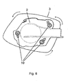
- Figure 6 describes the move of the mirror bezel 3 versus the installed mirror frame 2 when the connection 10 is inserted.
- the next step is a rotation, as marked by arrows around a center point of the mirror frame 2 and bezel 3, to slide the retention latch arms 14 along the slot inner walls.
- connection according the invention can be improved, where space is limited, by using additional connection means to support a rigid fixture of bezel at the mirror frame 2.
- Figure 7a to figure 7c show an embodiment of the invention using adapted bearing faces.
- the cup in cup design allows easy and full proof location of the two parts.
- the conical bearing surface 11 of the bezel 3 is adapted to follow the cup form of the conical bearing surface 12 of the frame 2.
- a retention hook/latch 23 can be incorporated, ref fig 8a/8b .
- the hook/latch 23 is designed to provide local increased retention where needed.
- the mirror frame 2, formed of plastic material PBT, includes a hook that entraps the bezel 3 during the rotation assembly.
- a further measure to improve retention is a frame/bezel stop.
- the stop rib 24 is formed in the bezel 3, figure 9 .
- the mirror frame 2 forms a counterpart, so when the retention latches are connected, the rotation of the bezel 2 versus the frame 2 ends at this rib 24.
- FIG 10a shows the actions of the cam clip in stages. Stage one is the initial location of the retention latch hood into the mirror frame. In this step the cam clip 25 is in clearance.
- the cam clip 25 consists of a guide 26, attached to the mirror frame's edge.
- Stage two shows the situation during the rotation around the arrow, wherein the guide 26 (attached to the bezel 3) is rotated around a radius
- the clip is ramped easily out of the way of rotation.
- stage three the clip is locked into place at the edge of mirror frame 2 into a notch 27 of the mirror bezel 3.
- the invention solution to assemble a rear view mirror at the vehicle uses, first step, the retention latch structures and a rotation around the center of the component to fix the connection and a stop to define the final position of the components versus each others.
- a group of components could be installed and fixed according the invention: as: mirror frame 2, mirror base 7, mirror housing 4,5, mirror bezel 3, mirror glass 6, mirror lighting means 30, glass actuator 9, glass 6 camera modules, pivot/powerfold actuators
- the lighting means comprises turn signal indicator, security lights, IR lighting for assistant systems, day running light, warning lights.
Landscapes
- Engineering & Computer Science (AREA)
- Multimedia (AREA)
- Mechanical Engineering (AREA)
- Rear-View Mirror Devices That Are Mounted On The Exterior Of The Vehicle (AREA)
Description
- The invention is related to an external rear view mirror assembly with the features of preamble of
claim 1. More especially the invention is related to a method to assemble such a rear view mirror. - External mirror assemblies are ubiquitous for contemporary motor vehicles and have long been used to aid the driver in operating the vehicle, especially in improving the rearward view of the driver. Selected components of the mirror assemblies must be connected during the assembly process. For example, a tilt actuator assembly used to adjust the mirror to provide a proper field of view is typically mounted to a rigid frame within the mirror assembly housing and is operably connected to a reflective element. The rigid frame is typically mounted within the mirror assembly housing to provide structural support to the housing and connecting the mirror assembly to the vehicle. The various connections are typically made with threaded fasteners, such as screws. The fasteners are separate components which an assembler must select in the proper number and properly install in order to correctly assemble the mirror.
- At times, the correct number of fasteners may not be installed. Also, the fasteners may not be tightened to the proper torque, thereby loosening over time so that the mirror assembly no longer operates satisfactorily. The failure to install the correct number of fasteners or to tighten the fasteners to the proper torque requires a costly replacement of the affected part(s) and can contribute to a reduction in vehicle safety due to operational failure of the mirror assembly.
- One aspect, the invention relates to an improved vehicular mirror assembly comprising a mirror bracket adapted to be mounted to a vehicle; a mirror housing mounted to the base and comprising a rearwardly-facing opening; a reflective element mounted within the mirror housing in register with the rearwardly-facing opening; a tilt actuator mounted to at least one of the mirror housing and the bracket, and to the reflective element for tiltably actuating the reflective element.
- A rear view mirror assembly mentioned in the preamble of
claim 1 is known byDE 198 30 173 A1 . - In prior art as
US 7448 589 a solution is disclosed that comprises: a snap-fit assembly for interconnecting selected components of a vehicular mirror assembly, the components comprising a mirror housing, a mounting frame having at least one of a first mounting aperture. The snap-fit assembly comprises a first mounting stud with a first portion having a first diameter and a second portion having a second diameter smaller than the first diameter. The second portion is adapted for snap fit communication with the first mounting aperture and the first portion is adapted for supporting communication with the mounting frame. - The snap fit solution according prior art connects support frame and mirror housing using several connectors to fix the components. The snap fit means have circular bodies more with conical internal faces, that are not easy to produce. In addition the reliability and the exact position definition is not optimized in this prior art.
- The objective of the invention is to provide an easy connection that can replace several separate connecting means in prior art and to ease assembly of a rear view mirror. An advantage of the intentional solution is that connector can be easily formed and used for the modular system at least to mount a bezel. The inventional connector assembly concept, allows a highly flexible and efficient assembly and gives a customer the freedom of design whilst conforming to the quality standards as required.
- Another advantage of the solution is the cost saving aspect. A modular system allows the standardized production of mirror basic components and an easy replacement of them during assembly. Variations can be realized for the customer.
- The invention is shown in the figures and shortly described thereafter.
-
Figure 1 shows a modular rear view mirror -
Figure 2a shows one part of connector (bezel) -
Fig. 2b shows the second part of connector -
Fig. 2c shows a frame - bezel connected part -
Figure 3a shows a schematic connection -
Fig. 3b shows a connected retention latch -
Figure 4a shows the connection -
Fig. 4b shows the retention latch with contact areas -
Figure 5 shows the retention latch arm -
Figure 6 shows the motion during assembly -
Figure 7a to 7c) show the bearing faces -
Figure 8a and b show a hook -
Figure 9 shows the stop face -
Figure 10 a and b) show a cam clip -
Figure 1 shows a schematic view of one example of a rearview mirror assembly 1. Themirror assembly 1 is mounted in a conventional fashion via amirror base 7 to a motor vehicle, which is not shown in the figure. Themirror assembly 1 comprises aupper mirror housing 4 and alower mirror housing 5. The central device is amirror frame 2 which is pivotal connected to themirror base 7. The pivot axis is referenced with 8 in the figure. As a stable support themirror frame 2 bears a glass actuator 9 and amirror glass 6. Amirror bezel 3 is connected to themirror frame 2. - The modular rear
view mirror assembly 1 is installed step by step. The support elements of the rear view mirror asmirror base 7 andmirror frame 2 are preinstalled and can be mounted on the motor vehicle at this stage. Theframe 2 is afterward equipped with themirror bezel 3 and the covers of the mirror housing, in the example the upper and thelower housing - The next figures and the description explain the connection of
mirror frame 2 andmirror bezel 3 via retention latches, asconnector parts 10. Theseretention latches 10 are accordingFigure 2c arranged at the extreme positions of amirror frame 2. The positions are circularly oriented and give the mirror head, withframe 2 andbezel 3, a structural rigidity at the extreme points. It is not mandatory that the points are arranged on a circle with one radius, but the center point must be the same. To optimize the connection theretention latches 10 are arranged with 120 degrees nominal spacing in between. -
Fig. 2a shows one part of the inventional connection,item 10 injection moulded in one piece with themirror bezel 3. The connection is a retention latch with aretention latch hood 13. Thisretention latch hood 13 has a slopedsurface 18, which helps locating thehood 13 into anopening 19 of the connector's counterpart. - The
retention latch hood 13 sits on the top of aretention latch arm 14, this has an approximately oblong cross section. Theretention latch arm 14 cross section, is slightly curved along a radius R1 seefigure 5 . The radius R1 is also used to curve the slot of the connector counterpart. Achamfer 15 at the bottom of thehood 13 helps to locate and lead the connector parts together. -
Figure 2b shows the counterpart of theconnector 10 in themirror frame 2. The connector has acircular opening 19 andchamfer 16 at the leading edge of aslot 17. -
Figure 3a shows in a schematic way, how themirror frame 2 and themirror bezel 3 are connected. Thebezel 3 is pressed/located into theframe 2. Theretention latch hoods 13 are pressed through theopenings 19 of theframe 2. After being inserted themirror bezel 3 is rotated around the center point. This results in a move of theretention latch hood 13 along theslot 17 of themirror frame 2 as described infigure 3b . - The
bezel 3 comprises aconical bearing surface 11 which has a counterpart in aconical bearing surface 12 of themirror frame 2. - The positioning of the
slots 17 gives a flexibility in frame and allows the designedinterference 20 to improve retention as seen infigure 4a orfigure 5 . Infigure 5 a cross section through theconnector 10 shows theopening 19 and thecurved slot 17. In theslot 17 the cross section of theretention latch arm 14 is visible. Theretention latch arm 14 hasinterference 20 at the inner radius wall of theslot 17 and aclearance 21 at the outside wall of the slot. This design ensures contact betweenframe 2 andbezel 3 on all latches. -
Figure 4b presents a cross section through the connector length. Theretention latch hook 13 sits at its final position on the mirror frame surface. Twocontact areas 22 are located on this surface. Thethird contact area 22 is due to theinterference 20 of the retention latch arm located at the side wall of theslot 17. The large contact areas prevent the retention latch to move. -
Figure 5 is a cross section along theframe 2. Theframe 2 has anopening 19 and aslot 17 to receive theretention latch hood 13. Theslot 17 is slightly curved with a Radius R1. When theretention latch hood 13 is inserted thearm 14 of the retention latch, faces aninterference area 20 and aclearance area 21. -
Figure 6 describes the move of themirror bezel 3 versus the installedmirror frame 2 when theconnection 10 is inserted. After theretention latch hood 13 is inserted into theopenings 19 of themirror frame 2, the next step is a rotation, as marked by arrows around a center point of themirror frame 2 andbezel 3, to slide theretention latch arms 14 along the slot inner walls. - The connection according the invention can be improved, where space is limited, by using additional connection means to support a rigid fixture of bezel at the
mirror frame 2. -
Figure 7a to figure 7c show an embodiment of the invention using adapted bearing faces. The cup in cup design allows easy and full proof location of the two parts. Theconical bearing surface 11 of thebezel 3 is adapted to follow the cup form of theconical bearing surface 12 of theframe 2. - Additionally, to improve the connection between
mirror frame 2 andbezel 3 where packaging space is restricted, the use of a retention hook/latch 23 can be incorporated, reffig 8a/8b . The hook/latch 23 is designed to provide local increased retention where needed. Themirror frame 2, formed of plastic material PBT, includes a hook that entraps thebezel 3 during the rotation assembly. - A further measure to improve retention is a frame/bezel stop. The
stop rib 24 is formed in thebezel 3,figure 9 . Themirror frame 2 forms a counterpart, so when the retention latches are connected, the rotation of thebezel 2 versus theframe 2 ends at thisrib 24. - Finally the assembled
frame 2 shown infigure 9 , (top side right), is fixed with the assembly of the lower housing, this traps theframe 2 between thebezel 3 and thelower housing part 5. - In addition, the final position after rotation is fixed with an
additional cam clip 25 according tofigure 10a /b.Figure 10a shows the actions of the cam clip in stages. Stage one is the initial location of the retention latch hood into the mirror frame. In this step thecam clip 25 is in clearance. Thecam clip 25 consists of aguide 26, attached to the mirror frame's edge. - Stage two shows the situation during the rotation around the arrow, wherein the guide 26 (attached to the bezel 3) is rotated around a radius The clip is ramped easily out of the way of rotation.
- In stage three the clip is locked into place at the edge of
mirror frame 2 into anotch 27 of themirror bezel 3. - The invention solution to assemble a rear view mirror at the vehicle uses, first step, the retention latch structures and a rotation around the center of the component to fix the connection and a stop to define the final position of the components versus each others.
- Despite the fact that the embodiment described above is related to a connection between a
mirror bezel 3 and amirror frame 2 the invention can be used to mount other components of the rearview mirror assembly 1. - The only restriction is that the components must have a design that allows the insert of the retention latch hood and the circular move of one of the component versus the other.
- A group of components could be installed and fixed according the invention: as:
mirror frame 2,mirror base 7,mirror housing mirror bezel 3,mirror glass 6, mirror lighting means 30, glass actuator 9,glass 6 camera modules, pivot/powerfold actuators - The lighting means comprises turn signal indicator, security lights, IR lighting for assistant systems, day running light, warning lights.
-
- 1.: Mirror Assembly
- 2.: Frame
- 3.: Bezel
- 4.: Upper Housing
- 5.: Lower Housing
- 6.: Glass
- 7.: Mirror Base
- 8.: Pivotal Axis
- 9.: Actuator
- 10. Connector Parts
- 11. Conical Bearing Surface Bezel
- 12. Conical Bearing Surface Frame
- 13. Retentional Latch Hood
- 14. Retentional Latch Arm
- 15.
Chamfer 1 at Hood - 16.
Chamfer 2 at Slot - 17. Slot
- 18.: Sloped Surface
- 19.: Circular Opening
- 20. Interference
- 21. Clearance
- 22. Contact Area
- 23. Frame Hook
- 24. Frame Bezel Stop
- 25. Cam Clip
- 26. Clip guide
- 27. Notch
Claims (10)
- Rear view mirror assembly with mirror frame (2), mirror base (7), mirror housing (4, 5, 3), mirror glass (6), glass actuator (9) that must be connected during assembly process with at least one retention latch (10), the retention latch (10) comprises a retention latch hood (13) with sloped faces (18) mounted on top of a rectangular retention latch arm (14) with an approximately oblong cross section formed in a first part and shifted along an adjacent slot (17) in a second part, characterized in that the approximately oblong cross section is formed to be inserted into a circular opening (19) and in that the slot (17) is curved with a radius (R1).
- Rear view mirror assembly according to claim 1 characterized in that the retention latches (10) are arranged circular around a center point of the two parts to be connected.
- Rear view mirror assembly according to claim 1 characterized in that the retention latch hood (13) has a chamfer (15).
- Rear view mirror assembly according to claim 1 characterized in that the opening (19) has a second chamfer (16).
- Rear view mirror assembly according to claim 1 characterized in that the retention latch arm (14) has an interference (20) at the inner wall of the slot (17) and a clearance (21) at the outer side wall of the slot (17).
- Rear view mirror assembly according to claim 1 characterized in that the two parts has additional conical bearing faces (11, 12) to support retention and provide rotational assembly axis.
- Rear view mirror assembly according to claim 1 characterized in that further fixation hooks and clips are mounted to at least one part.
- Process to assemble a rear view mirror according to claim 1 characterized by the steps:a) Inserting retention latch hoods (13) of a first part into openings (19) of a second partb) rotating the two parts versus each othersc) stopping rotation at stop means (24).
- Process according to claim 8 with the step:d) fixing of parts by at least one additional hook (23).
- Process according to claim 8 or 9 with the step:e) fixing at least two parts by a cam clip (25).
Priority Applications (3)
| Application Number | Priority Date | Filing Date | Title |
|---|---|---|---|
| EP09160611A EP2253510B1 (en) | 2009-05-19 | 2009-05-19 | Modular Rear View Mirror and Method to assemble it |
| CN201010183045.9A CN102009619B (en) | 2009-05-19 | 2010-05-18 | Modular rear view mirror and method to assemble it |
| US12/783,528 US8579444B2 (en) | 2009-05-19 | 2010-05-19 | Modular rear view mirror and method to assemble it |
Applications Claiming Priority (1)
| Application Number | Priority Date | Filing Date | Title |
|---|---|---|---|
| EP09160611A EP2253510B1 (en) | 2009-05-19 | 2009-05-19 | Modular Rear View Mirror and Method to assemble it |
Publications (2)
| Publication Number | Publication Date |
|---|---|
| EP2253510A1 EP2253510A1 (en) | 2010-11-24 |
| EP2253510B1 true EP2253510B1 (en) | 2013-01-02 |
Family
ID=41127648
Family Applications (1)
| Application Number | Title | Priority Date | Filing Date |
|---|---|---|---|
| EP09160611A Active EP2253510B1 (en) | 2009-05-19 | 2009-05-19 | Modular Rear View Mirror and Method to assemble it |
Country Status (3)
| Country | Link |
|---|---|
| US (1) | US8579444B2 (en) |
| EP (1) | EP2253510B1 (en) |
| CN (1) | CN102009619B (en) |
Cited By (10)
| Publication number | Priority date | Publication date | Assignee | Title |
|---|---|---|---|---|
| WO2019002627A1 (en) | 2017-06-30 | 2019-01-03 | Smr Patents Sarl | Rearview device with moveable head assembly and vehicle therewith |
| WO2019115746A1 (en) | 2017-12-15 | 2019-06-20 | Motherson Innovations Company Ltd. | Lighting device, rear-view device and motor vehicle |
| EP3632748A1 (en) | 2018-10-04 | 2020-04-08 | Motherson Innovations Company Ltd. | Rear view assembly and vehicle with such rear view assembly |
| US10661714B2 (en) | 2012-01-24 | 2020-05-26 | SMR Patents S.à.r.l. | Rearview device with moveable head assembly and method |
| US11220217B2 (en) | 2013-01-24 | 2022-01-11 | SMR Patents S.à.r.l. | Rearview device with moveable head assembly and method of assembling same |
| US11794649B2 (en) | 2012-01-24 | 2023-10-24 | SMR Patents S.à.r.l. | Rearview device with moveable head assembly and method of assembling same |
| EP4303076A2 (en) | 2018-03-15 | 2024-01-10 | SMR Patents S.à.r.l. | Rearview device with moveable head assembly |
| DE102023108330A1 (en) | 2023-03-31 | 2024-10-02 | Motherson Innovations Company Limited | EXTERIOR REARVIEW MIRROR ASSEMBLY FOR A VEHICLE, VEHICLE AND METHOD FOR ASSEMBLING THE EXTERIOR REARVIEW MIRROR ASSEMBLY |
| US12122297B2 (en) | 2016-11-14 | 2024-10-22 | SMR Patents S.à.r.l. | Rearview device with moveable head assembly and method of assembling same |
| US12151616B2 (en) | 2017-05-24 | 2024-11-26 | SMR Patents S.à.r.l. | Rearview device with moveable head assembly and method of assembling same |
Families Citing this family (19)
| Publication number | Priority date | Publication date | Assignee | Title |
|---|---|---|---|---|
| EP2415640B1 (en) * | 2010-08-03 | 2013-02-13 | SMR Patents S.à.r.l. | External rear view mirror and method for fitting same |
| FR2976534B1 (en) * | 2011-06-17 | 2014-08-08 | Renault Sa | TRIM AND SHIELD FOR ACCESS TO A BULB OF A LIGHTING OR SIGNALING DEVICE FOR A MOTOR VEHICLE |
| US11325534B2 (en) | 2013-09-10 | 2022-05-10 | SMR Patents S.à.r.l. | Assembly, method for assembling and disassembling such an assembly, and external rear view device and vehicle with such an assembly |
| US11618384B2 (en) * | 2017-02-22 | 2023-04-04 | SMR Patents S.à.r.l. | Assembly, method for assembling and disassembling such an assembly, and external rear view device and vehicle with such an assembly |
| US11738687B2 (en) * | 2012-09-11 | 2023-08-29 | SMR Patents S.à.r.l. | Assembly, method for assembling and disassembling such an assembly, and external rear view device and vehicle with such an assembly |
| US11865973B2 (en) | 2016-09-16 | 2024-01-09 | SMR Patents S.à.r.l. | Housing for a rear view element of a rear view device for a vehicle |
| EP3296157B1 (en) | 2016-09-16 | 2019-06-12 | SMR Patents S.à.r.l. | Housing for a rear view element of a rear view device for a vehicle |
| EP3442828B1 (en) * | 2017-06-30 | 2022-01-05 | SMR Patents Sarl | Assembly, method for assembling such an assembly, method for disassembling such an assembly, external rear vision device with such an assembly and motor vehicle with such a rear vision device |
| CN111212758B (en) * | 2017-11-09 | 2023-09-01 | 沃尔沃卡车集团 | rear view mirror assembly for vehicle |
| EP3717306B1 (en) * | 2017-12-01 | 2021-06-09 | Volvo Truck Corporation | A mirror assembly for a vehicle |
| NL2023038B1 (en) * | 2019-04-30 | 2020-11-23 | Mci Mirror Controls Int Netherlands B V | Adjustment tool |
| JP7126476B2 (en) * | 2019-06-05 | 2022-08-26 | 株式会社ホンダロック | vehicle door mirror |
| US11634079B2 (en) * | 2019-07-31 | 2023-04-25 | Tusimple, Inc. | Lidar mirror sensor assembly |
| DE102021107585B4 (en) * | 2021-03-25 | 2022-11-17 | Motherson Innovations Company Limited | BASIC ASSEMBLY, REAR VIEW DEVICE AND VEHICLE |
| EP4269173B1 (en) * | 2022-04-26 | 2024-09-25 | Ficomirrors, S.A. | External rear-view mirror for vehicles and a set of rear-view mirrors |
| US12441243B2 (en) * | 2022-04-29 | 2025-10-14 | Nissan North America, Inc. | Anti-theft countermeasures for mirror assemblies in vehicles |
| USD1066451S1 (en) * | 2022-11-10 | 2025-03-11 | Motherson Innovations Company Limited | Side view mirror actuator |
| USD1066177S1 (en) * | 2022-11-10 | 2025-03-11 | Motherson Innovations Company Limited | Side view mirror actuator |
| CN119370020B (en) * | 2024-11-27 | 2026-01-02 | 奇瑞汽车股份有限公司 | A car rearview mirror with door opening warning function and a car |
Family Cites Families (18)
| Publication number | Priority date | Publication date | Assignee | Title |
|---|---|---|---|---|
| US3096061A (en) * | 1961-06-28 | 1963-07-02 | Standard Mirror Co Inc | Support for mounting a rear vision mirror on a windshield |
| GB1202646A (en) * | 1968-03-07 | 1970-08-19 | Raydyot Ltd | Improvements relating to vehicle wing mirrors |
| GB1459101A (en) * | 1973-04-12 | 1976-12-22 | Wingard Ltd | Rear view mirrors for vehicles |
| FR2504075A1 (en) * | 1981-04-15 | 1982-10-22 | Hohe Kg | VEHICLE OUTSIDE MIRROR |
| US4678295A (en) * | 1985-04-05 | 1987-07-07 | Magna International Inc | Memory positioning system for remote control rear-view mirror |
| US4877214A (en) * | 1987-01-13 | 1989-10-31 | Murakami Kaimeido Co., Ltd. | Holding device of mirror element for rearview mirror |
| DE8914759U1 (en) * | 1989-12-15 | 1991-04-11 | Hohe Kg, 6981 Collenberg | Exterior mirror for a motor vehicle with attachable cap |
| US4998814A (en) * | 1990-02-12 | 1991-03-12 | Sheller-Globe Corporation | Exterior rearview mirror assembly |
| GB9208831D0 (en) * | 1992-04-23 | 1992-06-10 | Britax Wingard Ltd | Exterior rear view mirror for a motor vehicle |
| JP2564079Y2 (en) * | 1993-03-12 | 1998-03-04 | 株式会社村上開明堂 | Rearview mirror angle adjustment mechanism |
| US5721646A (en) * | 1996-02-23 | 1998-02-24 | Kam Truck Components, Inc. | Exterior rearview mirror for vehicles |
| DE19830173A1 (en) | 1998-07-06 | 2000-01-13 | Rothmayer Karl Heinz | Rear view mirror for motor vehicle, to improve vision through rear window, and to observe individuals of different stature in the back of the vehicle |
| US6347872B1 (en) * | 2001-02-20 | 2002-02-19 | Delbar Products Inc. | Snap-in rearview mirror assembly for vehicles |
| JP4109908B2 (en) * | 2002-06-11 | 2008-07-02 | 株式会社東海理化電機製作所 | Mirror device for vehicle |
| JP3967970B2 (en) * | 2002-07-02 | 2007-08-29 | 株式会社東海理化電機製作所 | Mirror device for vehicle |
| WO2004009408A1 (en) | 2002-07-19 | 2004-01-29 | Magna Donnelly North America, L.L.C. | Rear view mirror with snap connection |
| US6840639B2 (en) * | 2002-09-09 | 2005-01-11 | Zlatko Zadro | Dual magnification table top/wall mount mirror system |
| JP4009177B2 (en) * | 2002-10-25 | 2007-11-14 | 株式会社村上開明堂 | Vehicle door mirror |
-
2009
- 2009-05-19 EP EP09160611A patent/EP2253510B1/en active Active
-
2010
- 2010-05-18 CN CN201010183045.9A patent/CN102009619B/en active Active
- 2010-05-19 US US12/783,528 patent/US8579444B2/en active Active
Cited By (12)
| Publication number | Priority date | Publication date | Assignee | Title |
|---|---|---|---|---|
| US10661714B2 (en) | 2012-01-24 | 2020-05-26 | SMR Patents S.à.r.l. | Rearview device with moveable head assembly and method |
| US11794649B2 (en) | 2012-01-24 | 2023-10-24 | SMR Patents S.à.r.l. | Rearview device with moveable head assembly and method of assembling same |
| US11220217B2 (en) | 2013-01-24 | 2022-01-11 | SMR Patents S.à.r.l. | Rearview device with moveable head assembly and method of assembling same |
| US12122297B2 (en) | 2016-11-14 | 2024-10-22 | SMR Patents S.à.r.l. | Rearview device with moveable head assembly and method of assembling same |
| US12151616B2 (en) | 2017-05-24 | 2024-11-26 | SMR Patents S.à.r.l. | Rearview device with moveable head assembly and method of assembling same |
| WO2019002627A1 (en) | 2017-06-30 | 2019-01-03 | Smr Patents Sarl | Rearview device with moveable head assembly and vehicle therewith |
| WO2019115746A1 (en) | 2017-12-15 | 2019-06-20 | Motherson Innovations Company Ltd. | Lighting device, rear-view device and motor vehicle |
| EP4303076A2 (en) | 2018-03-15 | 2024-01-10 | SMR Patents S.à.r.l. | Rearview device with moveable head assembly |
| EP4467392A2 (en) | 2018-03-15 | 2024-11-27 | SMR Patents Sarl | Rearview device with moveable head assembly |
| EP3632748A1 (en) | 2018-10-04 | 2020-04-08 | Motherson Innovations Company Ltd. | Rear view assembly and vehicle with such rear view assembly |
| DE102023108330A1 (en) | 2023-03-31 | 2024-10-02 | Motherson Innovations Company Limited | EXTERIOR REARVIEW MIRROR ASSEMBLY FOR A VEHICLE, VEHICLE AND METHOD FOR ASSEMBLING THE EXTERIOR REARVIEW MIRROR ASSEMBLY |
| DE102023108330B4 (en) | 2023-03-31 | 2024-11-07 | Motherson Innovations Company Limited | EXTERIOR REARVIEW MIRROR ASSEMBLY FOR A VEHICLE, VEHICLE AND METHOD FOR ASSEMBLING THE EXTERIOR REARVIEW MIRROR ASSEMBLY |
Also Published As
| Publication number | Publication date |
|---|---|
| CN102009619B (en) | 2014-11-05 |
| CN102009619A (en) | 2011-04-13 |
| EP2253510A1 (en) | 2010-11-24 |
| US8579444B2 (en) | 2013-11-12 |
| US20100296189A1 (en) | 2010-11-25 |
Similar Documents
| Publication | Publication Date | Title |
|---|---|---|
| EP2253510B1 (en) | Modular Rear View Mirror and Method to assemble it | |
| US8979288B2 (en) | Snap fit connection in a rear view mirror | |
| US6347872B1 (en) | Snap-in rearview mirror assembly for vehicles | |
| KR100590156B1 (en) | Device for fixing the hydraulic control cylinder to the vehicle body structural element | |
| JP4116557B2 (en) | Retaining device for adjustable housing | |
| JP2010526700A (en) | Fixing device for vehicle functional unit | |
| US20110317445A1 (en) | Exterior rear view mirror | |
| EP4063152B1 (en) | 2k door gasket, rear view device, vehicle and assembling and attachment method | |
| JP4896390B2 (en) | Support arm for vehicle mirror | |
| US20180320720A1 (en) | Drive assembly for a vehicle accessory including a multipurpose coupler | |
| EP2212155B2 (en) | Mounting construction for an outside mirror unit | |
| CN114248643A (en) | Charging module device for a motor vehicle, charging module system | |
| CN118647525A (en) | Rear view device with actuator and gasket seal head mover | |
| CN116685864A (en) | Adjusting device for adjusting the position of a sensor module, vehicle component and method for adjusting the position of a sensor module | |
| KR20020081209A (en) | Mount for connecting automotive fan motor to housing | |
| CN112874660B (en) | Bracket device for an outer covering of a motor vehicle | |
| US12242174B2 (en) | Device for securing an optical device | |
| AU782506B2 (en) | Adjustment drive with an adjustable potentiometer | |
| JP2001317532A (en) | Device for locking sheath of remote control device via cable | |
| US20230166665A1 (en) | Sensor device for fastening to the inside of a vehicle window | |
| CN110871855A (en) | Air guide device for vehicle | |
| US20110273868A1 (en) | Lighting system for installation in ceiling portion of passenger compartment | |
| KR101538693B1 (en) | Air conditioning system for automotive vehicles | |
| CN101008417B (en) | Fastening device | |
| JP2023068329A (en) | Attachments for vehicle interior materials |
Legal Events
| Date | Code | Title | Description |
|---|---|---|---|
| PUAI | Public reference made under article 153(3) epc to a published international application that has entered the european phase |
Free format text: ORIGINAL CODE: 0009012 |
|
| 17P | Request for examination filed |
Effective date: 20100111 |
|
| AK | Designated contracting states |
Kind code of ref document: A1 Designated state(s): AT BE BG CH CY CZ DE DK EE ES FI FR GB GR HR HU IE IS IT LI LT LU LV MC MK MT NL NO PL PT RO SE SI SK TR |
|
| GRAP | Despatch of communication of intention to grant a patent |
Free format text: ORIGINAL CODE: EPIDOSNIGR1 |
|
| GRAJ | Information related to disapproval of communication of intention to grant by the applicant or resumption of examination proceedings by the epo deleted |
Free format text: ORIGINAL CODE: EPIDOSDIGR1 |
|
| GRAS | Grant fee paid |
Free format text: ORIGINAL CODE: EPIDOSNIGR3 |
|
| GRAP | Despatch of communication of intention to grant a patent |
Free format text: ORIGINAL CODE: EPIDOSNIGR1 |
|
| GRAP | Despatch of communication of intention to grant a patent |
Free format text: ORIGINAL CODE: EPIDOSNIGR1 |
|
| GRAA | (expected) grant |
Free format text: ORIGINAL CODE: 0009210 |
|
| AK | Designated contracting states |
Kind code of ref document: B1 Designated state(s): AT BE BG CH CY CZ DE DK EE ES FI FR GB GR HR HU IE IS IT LI LT LU LV MC MK MT NL NO PL PT RO SE SI SK TR |
|
| REG | Reference to a national code |
Ref country code: GB Ref legal event code: FG4D |
|
| REG | Reference to a national code |
Ref country code: AT Ref legal event code: REF Ref document number: 591400 Country of ref document: AT Kind code of ref document: T Effective date: 20130115 Ref country code: CH Ref legal event code: EP |
|
| REG | Reference to a national code |
Ref country code: IE Ref legal event code: FG4D |
|
| REG | Reference to a national code |
Ref country code: DE Ref legal event code: R096 Ref document number: 602009012381 Country of ref document: DE Effective date: 20130307 |
|
| REG | Reference to a national code |
Ref country code: AT Ref legal event code: MK05 Ref document number: 591400 Country of ref document: AT Kind code of ref document: T Effective date: 20130102 |
|
| REG | Reference to a national code |
Ref country code: NL Ref legal event code: VDEP Effective date: 20130102 |
|
| PG25 | Lapsed in a contracting state [announced via postgrant information from national office to epo] |
Ref country code: SI Free format text: LAPSE BECAUSE OF FAILURE TO SUBMIT A TRANSLATION OF THE DESCRIPTION OR TO PAY THE FEE WITHIN THE PRESCRIBED TIME-LIMIT Effective date: 20130102 |
|
| REG | Reference to a national code |
Ref country code: LT Ref legal event code: MG4D |
|
| PG25 | Lapsed in a contracting state [announced via postgrant information from national office to epo] |
Ref country code: CZ Free format text: LAPSE BECAUSE OF FAILURE TO SUBMIT A TRANSLATION OF THE DESCRIPTION OR TO PAY THE FEE WITHIN THE PRESCRIBED TIME-LIMIT Effective date: 20130102 Ref country code: IS Free format text: LAPSE BECAUSE OF FAILURE TO SUBMIT A TRANSLATION OF THE DESCRIPTION OR TO PAY THE FEE WITHIN THE PRESCRIBED TIME-LIMIT Effective date: 20130502 Ref country code: NO Free format text: LAPSE BECAUSE OF FAILURE TO SUBMIT A TRANSLATION OF THE DESCRIPTION OR TO PAY THE FEE WITHIN THE PRESCRIBED TIME-LIMIT Effective date: 20130402 Ref country code: SE Free format text: LAPSE BECAUSE OF FAILURE TO SUBMIT A TRANSLATION OF THE DESCRIPTION OR TO PAY THE FEE WITHIN THE PRESCRIBED TIME-LIMIT Effective date: 20130102 Ref country code: LT Free format text: LAPSE BECAUSE OF FAILURE TO SUBMIT A TRANSLATION OF THE DESCRIPTION OR TO PAY THE FEE WITHIN THE PRESCRIBED TIME-LIMIT Effective date: 20130102 Ref country code: BE Free format text: LAPSE BECAUSE OF FAILURE TO SUBMIT A TRANSLATION OF THE DESCRIPTION OR TO PAY THE FEE WITHIN THE PRESCRIBED TIME-LIMIT Effective date: 20130102 Ref country code: BG Free format text: LAPSE BECAUSE OF FAILURE TO SUBMIT A TRANSLATION OF THE DESCRIPTION OR TO PAY THE FEE WITHIN THE PRESCRIBED TIME-LIMIT Effective date: 20130402 Ref country code: ES Free format text: LAPSE BECAUSE OF FAILURE TO SUBMIT A TRANSLATION OF THE DESCRIPTION OR TO PAY THE FEE WITHIN THE PRESCRIBED TIME-LIMIT Effective date: 20130413 Ref country code: AT Free format text: LAPSE BECAUSE OF FAILURE TO SUBMIT A TRANSLATION OF THE DESCRIPTION OR TO PAY THE FEE WITHIN THE PRESCRIBED TIME-LIMIT Effective date: 20130102 |
|
| PG25 | Lapsed in a contracting state [announced via postgrant information from national office to epo] |
Ref country code: NL Free format text: LAPSE BECAUSE OF FAILURE TO SUBMIT A TRANSLATION OF THE DESCRIPTION OR TO PAY THE FEE WITHIN THE PRESCRIBED TIME-LIMIT Effective date: 20130102 Ref country code: GR Free format text: LAPSE BECAUSE OF FAILURE TO SUBMIT A TRANSLATION OF THE DESCRIPTION OR TO PAY THE FEE WITHIN THE PRESCRIBED TIME-LIMIT Effective date: 20130403 Ref country code: PL Free format text: LAPSE BECAUSE OF FAILURE TO SUBMIT A TRANSLATION OF THE DESCRIPTION OR TO PAY THE FEE WITHIN THE PRESCRIBED TIME-LIMIT Effective date: 20130102 Ref country code: LV Free format text: LAPSE BECAUSE OF FAILURE TO SUBMIT A TRANSLATION OF THE DESCRIPTION OR TO PAY THE FEE WITHIN THE PRESCRIBED TIME-LIMIT Effective date: 20130102 Ref country code: FI Free format text: LAPSE BECAUSE OF FAILURE TO SUBMIT A TRANSLATION OF THE DESCRIPTION OR TO PAY THE FEE WITHIN THE PRESCRIBED TIME-LIMIT Effective date: 20130102 Ref country code: PT Free format text: LAPSE BECAUSE OF FAILURE TO SUBMIT A TRANSLATION OF THE DESCRIPTION OR TO PAY THE FEE WITHIN THE PRESCRIBED TIME-LIMIT Effective date: 20130502 |
|
| PG25 | Lapsed in a contracting state [announced via postgrant information from national office to epo] |
Ref country code: HR Free format text: LAPSE BECAUSE OF FAILURE TO SUBMIT A TRANSLATION OF THE DESCRIPTION OR TO PAY THE FEE WITHIN THE PRESCRIBED TIME-LIMIT Effective date: 20130102 |
|
| PG25 | Lapsed in a contracting state [announced via postgrant information from national office to epo] |
Ref country code: EE Free format text: LAPSE BECAUSE OF FAILURE TO SUBMIT A TRANSLATION OF THE DESCRIPTION OR TO PAY THE FEE WITHIN THE PRESCRIBED TIME-LIMIT Effective date: 20130102 Ref country code: RO Free format text: LAPSE BECAUSE OF FAILURE TO SUBMIT A TRANSLATION OF THE DESCRIPTION OR TO PAY THE FEE WITHIN THE PRESCRIBED TIME-LIMIT Effective date: 20130102 Ref country code: SK Free format text: LAPSE BECAUSE OF FAILURE TO SUBMIT A TRANSLATION OF THE DESCRIPTION OR TO PAY THE FEE WITHIN THE PRESCRIBED TIME-LIMIT Effective date: 20130102 Ref country code: DK Free format text: LAPSE BECAUSE OF FAILURE TO SUBMIT A TRANSLATION OF THE DESCRIPTION OR TO PAY THE FEE WITHIN THE PRESCRIBED TIME-LIMIT Effective date: 20130102 |
|
| PLBE | No opposition filed within time limit |
Free format text: ORIGINAL CODE: 0009261 |
|
| STAA | Information on the status of an ep patent application or granted ep patent |
Free format text: STATUS: NO OPPOSITION FILED WITHIN TIME LIMIT |
|
| PG25 | Lapsed in a contracting state [announced via postgrant information from national office to epo] |
Ref country code: CY Free format text: LAPSE BECAUSE OF FAILURE TO SUBMIT A TRANSLATION OF THE DESCRIPTION OR TO PAY THE FEE WITHIN THE PRESCRIBED TIME-LIMIT Effective date: 20130102 |
|
| 26N | No opposition filed |
Effective date: 20131003 |
|
| PG25 | Lapsed in a contracting state [announced via postgrant information from national office to epo] |
Ref country code: MC Free format text: LAPSE BECAUSE OF FAILURE TO SUBMIT A TRANSLATION OF THE DESCRIPTION OR TO PAY THE FEE WITHIN THE PRESCRIBED TIME-LIMIT Effective date: 20130102 Ref country code: IT Free format text: LAPSE BECAUSE OF FAILURE TO SUBMIT A TRANSLATION OF THE DESCRIPTION OR TO PAY THE FEE WITHIN THE PRESCRIBED TIME-LIMIT Effective date: 20130102 |
|
| REG | Reference to a national code |
Ref country code: CH Ref legal event code: PL |
|
| REG | Reference to a national code |
Ref country code: DE Ref legal event code: R097 Ref document number: 602009012381 Country of ref document: DE Effective date: 20131003 |
|
| PG25 | Lapsed in a contracting state [announced via postgrant information from national office to epo] |
Ref country code: LI Free format text: LAPSE BECAUSE OF NON-PAYMENT OF DUE FEES Effective date: 20130531 Ref country code: CH Free format text: LAPSE BECAUSE OF NON-PAYMENT OF DUE FEES Effective date: 20130531 |
|
| REG | Reference to a national code |
Ref country code: IE Ref legal event code: MM4A |
|
| PG25 | Lapsed in a contracting state [announced via postgrant information from national office to epo] |
Ref country code: IE Free format text: LAPSE BECAUSE OF NON-PAYMENT OF DUE FEES Effective date: 20130519 |
|
| PG25 | Lapsed in a contracting state [announced via postgrant information from national office to epo] |
Ref country code: MT Free format text: LAPSE BECAUSE OF FAILURE TO SUBMIT A TRANSLATION OF THE DESCRIPTION OR TO PAY THE FEE WITHIN THE PRESCRIBED TIME-LIMIT Effective date: 20130102 |
|
| PG25 | Lapsed in a contracting state [announced via postgrant information from national office to epo] |
Ref country code: TR Free format text: LAPSE BECAUSE OF FAILURE TO SUBMIT A TRANSLATION OF THE DESCRIPTION OR TO PAY THE FEE WITHIN THE PRESCRIBED TIME-LIMIT Effective date: 20130102 |
|
| PG25 | Lapsed in a contracting state [announced via postgrant information from national office to epo] |
Ref country code: LU Free format text: LAPSE BECAUSE OF NON-PAYMENT OF DUE FEES Effective date: 20130519 Ref country code: HU Free format text: LAPSE BECAUSE OF FAILURE TO SUBMIT A TRANSLATION OF THE DESCRIPTION OR TO PAY THE FEE WITHIN THE PRESCRIBED TIME-LIMIT; INVALID AB INITIO Effective date: 20090519 Ref country code: MK Free format text: LAPSE BECAUSE OF FAILURE TO SUBMIT A TRANSLATION OF THE DESCRIPTION OR TO PAY THE FEE WITHIN THE PRESCRIBED TIME-LIMIT Effective date: 20130102 |
|
| REG | Reference to a national code |
Ref country code: FR Ref legal event code: PLFP Year of fee payment: 8 |
|
| REG | Reference to a national code |
Ref country code: FR Ref legal event code: PLFP Year of fee payment: 9 |
|
| REG | Reference to a national code |
Ref country code: FR Ref legal event code: PLFP Year of fee payment: 10 |
|
| REG | Reference to a national code |
Ref country code: DE Ref legal event code: R084 Ref document number: 602009012381 Country of ref document: DE |
|
| P01 | Opt-out of the competence of the unified patent court (upc) registered |
Effective date: 20230616 |
|
| PGFP | Annual fee paid to national office [announced via postgrant information from national office to epo] |
Ref country code: DE Payment date: 20250519 Year of fee payment: 17 |
|
| PGFP | Annual fee paid to national office [announced via postgrant information from national office to epo] |
Ref country code: GB Payment date: 20250522 Year of fee payment: 17 |
|
| PGFP | Annual fee paid to national office [announced via postgrant information from national office to epo] |
Ref country code: FR Payment date: 20250526 Year of fee payment: 17 |