EP3632740B1 - Air duct for ventilation seat and vehicle ventilation seat having same - Google Patents
Air duct for ventilation seat and vehicle ventilation seat having same Download PDFInfo
- Publication number
- EP3632740B1 EP3632740B1 EP19786895.3A EP19786895A EP3632740B1 EP 3632740 B1 EP3632740 B1 EP 3632740B1 EP 19786895 A EP19786895 A EP 19786895A EP 3632740 B1 EP3632740 B1 EP 3632740B1
- Authority
- EP
- European Patent Office
- Prior art keywords
- air
- air duct
- duct
- ventilation seat
- seat
- Prior art date
- Legal status (The legal status is an assumption and is not a legal conclusion. Google has not performed a legal analysis and makes no representation as to the accuracy of the status listed.)
- Active
Links
Images






Classifications
-
- B—PERFORMING OPERATIONS; TRANSPORTING
- B60—VEHICLES IN GENERAL
- B60N—SEATS SPECIALLY ADAPTED FOR VEHICLES; VEHICLE PASSENGER ACCOMMODATION NOT OTHERWISE PROVIDED FOR
- B60N2/00—Seats specially adapted for vehicles; Arrangement or mounting of seats in vehicles
- B60N2/56—Heating or ventilating devices
- B60N2/5607—Heating or ventilating devices characterised by convection
- B60N2/5621—Heating or ventilating devices characterised by convection by air
- B60N2/5657—Heating or ventilating devices characterised by convection by air blown towards the seat surface
-
- A—HUMAN NECESSITIES
- A47—FURNITURE; DOMESTIC ARTICLES OR APPLIANCES; COFFEE MILLS; SPICE MILLS; SUCTION CLEANERS IN GENERAL
- A47C—CHAIRS; SOFAS; BEDS
- A47C7/00—Parts, details, or accessories of chairs or stools
- A47C7/62—Accessories for chairs
- A47C7/72—Adaptations for incorporating lamps, radio sets, bars, telephones, ventilation, heating or cooling arrangements or the like
- A47C7/74—Adaptations for incorporating lamps, radio sets, bars, telephones, ventilation, heating or cooling arrangements or the like for ventilation, heating or cooling
-
- B—PERFORMING OPERATIONS; TRANSPORTING
- B60—VEHICLES IN GENERAL
- B60N—SEATS SPECIALLY ADAPTED FOR VEHICLES; VEHICLE PASSENGER ACCOMMODATION NOT OTHERWISE PROVIDED FOR
- B60N2/00—Seats specially adapted for vehicles; Arrangement or mounting of seats in vehicles
- B60N2/56—Heating or ventilating devices
Definitions
- the present invention relates generally to an air duct for a ventilation seat and a ventilation seat having the same for a vehicle. More particularly, the present invention relates to an air duct for a ventilation seat and a ventilation seat having the same for a vehicle, in which an air flow structure is improved and it is possible to provide a comfortable seating feel to a user.
- An air conditioning apparatus is used to keep the temperature, the humidity, the air cleanliness, and the air flow of a space pleasant, and particularly, the importance of the air conditioning apparatus becomes more prominent in an enclosed space such as a vehicle.
- an air conditioning apparatus applied to a vehicle is provided with a cooling and heating device composed of an air conditioner and a heater to provide air on the front and side of the inside of the vehicle, but a vehicle seat, with which an occupant's body is brought directly into contact, is not provided with the air from the cooling and heating device described above, which is a factor that reduces ride comfort of the occupant.
- Korean Patent No. 10-1280775 by using a seat configured such that outside air is sucked and the air is discharged through an air discharge hole formed in the seat via an air transfer hole having a predetermined shape, it is possible to provide comfortable ride and to reduce unnecessary energy consumption by directly transmitting the cooling effect to an occupant.
- the ventilation seat configured as described above is problematic in that the air transfer hole for guiding air and a fan for sucking air are generally inserted into the seat, which causes discomfort to the occupant when the occupant sits on the seat, so the ride comfort is deteriorated.
- the air transfer hole for guiding air is made of a material such as memory foam that absorbs an external force while maintaining a predetermined shape in order to improve the ride comfort, the space defined in the air transfer hole is blocked when an occupant sits on the seat and an external force is applied to the seat, so air may not be smoothly transported.
- a seat including a mesh that is inserted into back and front surfaces of vent holes to fill the vent holes, which are formed in a back pad structure in the forward and backward directions.
- the mesh is problematic in that an air passage may be clogged by the occupant's weight at the time of sitting, and the size of a blower must be larger in order to increase the efficiency.
- the conventional ventilation seat is problematic in that when an external force is applied to the seat by an occupant, the sucked air leaks into a fine gap formed on the seat of the vehicle, so noise may be generated due to the fan under load.
- an object of the present invention is to provide an air duct for a ventilation seat and a ventilation seat having the same for a vehicle, in which it is possible to uniformly discharge sucked air to a seat of a vehicle and to minimize the discomfort experienced by a vehicle occupant, thereby providing a comfortable ride.
- Another object of the present invention is to provide an air duct for a ventilation seat and a ventilation seat having the same for a vehicle, in which it is possible to minimize an external force transmitted to a panel provided in a vehicle seat to guide the flow of air, thereby facilitating the air flow and reducing noise.
- the present invention provides an air duct for a ventilation seat in accordance with claim 1.
- the spacer is configured such that protrusions are provided on at least one of the lower surface and the upper surface to extend toward the other surface at predetermined intervals.
- the upper surface is configured such that a gentle conical protruding portion is provided on an inner surface thereof facing the air inlet so as to diffuse incoming air to ends of the corners; and the lower surface is fastened by using a fastener to a conveying duct for conveying air from a fan, and includes a locking piece provided to intersect in a U shape with the fastener fastening the conveying duct.
- the upper surface or the lower surface includes a wrinkle portion to be bent at a predetermined angle at a time of sitting.
- a nonwoven fabric may be attached to a bottom of the lower surface.
- the upper surface is configured such that a spiral protrusion is provided on an inner side of each of the air outlets.
- the air duct constituted by the upper surface and the lower surface is provided with a fan and a conveying duct at a side thereof; and the upper surface or the lower surface includes a bent portion that partitions a flow direction of incoming air and guides air flow.
- the upper surface or the lower surface may include a first bent portion configured to be bent at a predetermined angle at a time of sitting while partitioning a flow direction of incoming air into at least one of a central portion, a left side, and a right side, and the first bent portion may be configured such that an end thereof is gently curved toward an air inlet side.
- the upper surface or the lower surface includes a second bent portion configured to be bent in a direction perpendicular to a flow direction of air flowing in the air duct.
- the second bent portion may include: an upper convex portion configured such that an upper inner surface of the air duct corresponding to a seat bottom of the upper surface is convex downwardly; and a lower convex portion configured such that an inner surface of the lower surface diagonally facing the upper convex portion is convex upwardly, wherein the upper convex portion and the lower convex portion are spaced apart from each other at a predetermined interval.
- the air duct of includes: a lower chamber of hard material configured such that the upper surface is provided with a discharge hole, the lower surface is provided with an air inlet, and the corners of the upper surface and the lower surface are attached together to form a chamber-type air passage; and an adapter of soft material provided with a plurality of air outlets connected with the discharge hole of the lower chamber to be connected to a discharge passage of a foam pad.
- a chamber constituted by the upper surface and the lower surface is configured such that a width thereof is gradually increased from an air inlet side toward an inside of the chamber and then is constant.
- a ventilation seat is configured in a form of a seat back part or a seat bottom part, the ventilation seat including: the upper surface provided with the plurality of air outlets; the lower surface provided with the air inlet, and configured such that the corners thereof are attached to the corners of the upper surface to form the air passage; the spacer provided on at least one of the lower surface and the upper surface to extend toward the other surface; a cushion part connected to the air outlets of the upper surface and an air passage of the foam pad; and a support means supporting the lower surface.
- the clamping portion has an important technical effect that secures a flow path by stably forming a space between the upper surface and the lower surface, and enables the conveying duct to be stably fixed to the lower surface.
- FIG. 1 is a perspective view showing an upper surface of an air duct for a ventilation seat according to a first embodiment of the present invention
- FIG. 2 is an exemplary view showing a lower surface of the air duct for a ventilation seat according to the first embodiment of the present invention.
- an air duct 10 for a ventilation seat according to the embodiment has a chamber-type structure including an upper surface 110, a lower surface 120, and a spacer 130.
- the upper surface 110 is formed with a plurality of air outlets 111.
- the lower surface 120 is formed with an air inlet, and corners thereof are attached to corners of the upper surface to form a chamber-type air passage.
- the spacer 130 is formed on at least one surface of the lower surface and the upper surface toward the other surface.
- FIG. 11 is an exemplary view showing a cap 1000 of the air duct for a ventilation seat according to an embodiment of the present invention
- FIG. 12 is an exemplary view showing a cross-section of the cap 1000 of the air duct for a ventilation seat according to an embodiment of the present invention. As shown in FIGS.
- the air outlet 111 of the air duct may be provided with a cylindrical cap 1000 on the outer surface thereof to be engaged with the discharge passage of the foam pad, wherein the cap 1000 is formed on the inner side thereof with a threaded protrusion to form a vortex.
- the upper surface is provided with a clamping portion 113 so as to be clamped to clamping means provided on opposite sides of a fastener 121 of the lower surface of FIG. 2 . Accordingly, the space between the upper surface and the lower surface can be stably formed, and stable fixing is possible even when the air duct is fastened to a conveying duct 300.
- the spacer 130 of the air duct 10 for a ventilation seat can prevent clogging of the air passage due to the weight of an occupant by forming a plurality of protrusions at predetermined intervals on the inner surface of the corresponding position where the human body is brought in contact at the time of sitting.
- the air outlet 111 may be variously designed according to the position of the air passage of the foam pad according to the type of vehicle.
- the air duct 10 for a ventilation seat is configured such that a gentle conical protruding portion (not shown) is provided on the inner side of the upper surface, which is the inner side of the air duct for a ventilation seat facing the air inlet of the lower surface, thereby diffusing the incoming air to the inner corners of the air duct for a ventilation seat.
- a gentle conical protruding portion (not shown) is provided on the inner side of the upper surface, which is the inner side of the air duct for a ventilation seat facing the air inlet of the lower surface, thereby diffusing the incoming air to the inner corners of the air duct for a ventilation seat.
- the bending of one end of the air duct 10 for a ventilation seat may be changed according to the shape of the foam pad.
- the air duct for a ventilation seat is fastened to a conveying duct 300 for conveying air from a fan 200.
- the air duct 10 for a ventilation seat includes a locking piece 122 formed at the bottom thereof to intersect with the fastener 121 fastened to the conveying duct 300 in a U shape. Due to the configuration of the locking piece 122 formed to intersect in the U shape, the air duct can be fastened by the weight of the foam pad and the seat placed on the upper portion of the air duct without a fastening means, and it is possible to prevent separation due to the vibration of the fan or conveying duct.
- the conveying duct 300 is provided with an elastic member 310 that includes a first elastic member 311 connected to the fan 200 and a second elastic member 312 connected to the lower surface of the air duct, thereby reducing the vibration transmitted from the fan 200.
- FIG. 3 is an exemplary view showing a shape of a seat back part 20 of an air duct for a ventilation seat according to a second embodiment of the present invention.
- the air duct may include a wrinkle portion 123 configured such that wrinkles are formed on one surface of an upper surface and a lower surface in a horizontal direction so as to be bent at a predetermined angle at the time of sitting against the seat back part.
- a nonwoven fabric 140 may be attached to the lower surface of the air duct 120 for a ventilation seat to reduce vibration of the fan or the conveying duct.
- a support means 150 may be provided to support the external force transmitted by the occupant's weight, and preferably, the support means 150 is formed in a shape that is bent at least once so as to disperse and support the transmitted external force.
- the conveying duct 300 may be provided with at least one elastic member 310 to absorb the external force applied thereto.
- the spiral protrusion 112 is formed on the inner side of the air outlet 111 so as to form a vortex in the discharge passage of the foam pad when the air outlet 111 of the upper surface 110 is coupled to the foam pad of the seat cushion part of the vehicle.
- the air outlet 111 of the air duct may be provided with the spiral cap 1000 shown in FIGS. 11 and 12 to form a vortex. With this structure, the discharged air is discharged in a vortex form to increase the strength and pressure of the air flow.
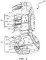
- FIG. 4 is an inside perspective view showing a seat back part and a seat bottom part of a ventilation seat for a vehicle having the air duct according to the first embodiment and the second embodiment of the present invention
- FIG. 5 is an exemplary view showing a rear side of the ventilation seat for a vehicle having the air duct according to the first embodiment and the second embodiment of the present invention
- FIG. 6 is an exemplary view showing a cross-section of the ventilation seat for a vehicle having the air duct according to the first embodiment and the second embodiment of the present invention.
- a seat bottom part 30 of a ventilation seat 400 for a vehicle having an air duct for a ventilation seat includes an air duct 410 for a ventilation seat, a support means 420, and a cushion part 430.
- the air duct 410 for a ventilation seat is provided with a wrinkle portion 411 at a position corresponding to the buttocks portion at the time of sitting so as to be bent at the time of sitting.
- the support means 420 is provided to support the bottom of the air duct 410 for a ventilation seat, and the support means 420 includes a nonwoven fabric 421 attached to the bottom of the air duct 410 for a ventilation seat to reduce vibration transmitted from the fan or the conveying duct.
- the cushion part 430 is configured such that an air passage thereof is connected to the air outlet 412 of the air duct 410 for a ventilation seat to discharge air through a ventilation seat hole 431.
- a seat back part 40 of the ventilation seat 400 for a vehicle having an air duct for a ventilation seat includes an air duct 440 for a ventilation seat, a support means 450, and a cushion part 460.
- the air duct 440 for a ventilation seat is formed in the shape of the seat back part 40, and a wrinkle portion 441 is provided at a position corresponding to the back of the occupant at the time of sitting to give comfort.
- the seat back part is provided with the support means 450 for supporting the back side of the air duct 440 for a ventilation seat, and a nonwoven fabric 451 is attached to the rear surface of the support means 450 to reduce vibration transmitted from the fan or the conveying duct.
- the cushion part 460 is configured such that an air passage thereof is connected to the air outlet 442 of the air duct 440 for a ventilation seat to discharge air through a ventilation seat hole 461.
- Each of the air outlets 412 and 442 of FIG. 4 may be provided with the spiral protrusion or a structure of a spiral cap on the inner side thereof, as shown in FIGS. 1 , 11 , and 12 .
- the ventilation seat 400 for a vehicle having an air duct for a ventilation seat may be provided with at least one elastic member 310 at the conveying duct 300 to absorb the external force applied thereto when the fan 200 and the conveying duct 300 are connected with each other.
- the elastic member 310 includes: the first elastic member 311 formed with wrinkles at a portion of the conveying duct 300 connected to the fan 200 side; and the second elastic member 312 formed with wrinkles at a portion of the conveying duct 300 connected to the air duct side.
- the support means 450 and the nonwoven fabric 451 are provided reduce vibration due to seating and vibration transmitted from the fan including the supporting portion and the nonwoven fabric.
- the fan 200 and the conveying duct 300 may be separately provided and connected to the air ducts of the seat back part 40 and the seat bottom part 30, or may be integrally provided.
- the ventilation seat 400 for a vehicle having the air duct 410 of the seat bottom part 30 and the air duct 440 of the seat back part 40 has been described with reference to the first and second embodiments, it is of course possible to apply an air duct for a ventilation seat of the embodiment described below.
- the seat bottom part 30 of FIG. 6 is configured such that the air duct 410, at which the fan 200 and the conveying duct 300 are connected with each other, is supported by the support means 420, vibration is reduced by the elastic member 310 of the conveying duct 300, and the nonwoven fabric is provided between the support means 420 and the air duct 410 to reduce vibration.
- the air outlet of the air duct 410 is connected with the air passage of the cushion part 430 such that air is discharged through the ventilation seat hole 431.
- the seat back part 40 has been described above with reference to FIG. 4 , and a description thereof will be omitted.
- FIG. 7 is an exemplary view showing a shape of an air duct 50 for a ventilation seat according to a third embodiment of the present invention
- FIG. 8 is a sectional perspective view showing the shape of the air duct 50 for a ventilation seat according to the third embodiment of the present invention.
- the fan 200 and the conveying duct 300 may be integrally provided at one side of the air duct 50 for a ventilation seat.
- the air duct 50 for a ventilation seat includes a bent portion 700 that partitions or induces the flow direction of the incoming air.
- the bent portion 700 includes: a first bent portion 710 configured to be bent at a predetermined angle at the time of sitting while dividing the flow direction of the air flow into a central portion, a left side, and a right side; and a second bent portion 720 configured to be bent in a vertical direction based on the flow direction of the air flowing in the air duct 50.
- the first bent portion 710 is configured to be bent at a predetermined angle at the time of sitting while a partition portion 711 in the form of a partition plate or a protrusion divides the direction of the air flow introduced in the air duct 50 into the central portion, the left side, and the right side.
- the first bent portion 710 is configured, as shown in FIG. 7 , such that an air inlet side end 712 is gently curved so as to induce the direction of the air flow to the central portion, the left side, and the right side.
- the air duct 50 for a ventilation seat is formed to be gradually wider from the air inlet side toward the inside and then have a predetermined width, and the end of the first bent portion is gently bent along the appearance of the air duct 50 toward the air inlet side to evenly induce the direction of the air flow by dividing the air duct into the central portion, the left side, and the right side.
- the second bent portion 720 includes: an upper convex portion 721 configured such that an upper inner surface of the air duct corresponding to the buttocks at the time of sitting is convex downwardly; and a lower convex portion 722 configured such that a lower inner surface of the air duct diagonally facing the upper convex portion 721 is convex upwardly. Due to the second bent portion 720, the air duct 50 for a ventilation seat can form a wavy air passage, and allows the air flow to smoothly flow to the corners of the air duct while being bent by the occupant's weight at the time of sitting.
- FIG. 8 is a sectional perspective view showing the shape of the air duct 50 for a ventilation seat according to the third embodiment of the present invention, wherein the spacer 130 is provided in the form of a protrusion on either the upper surface or the lower surface.
- the protrusion of the spacer 130 may be protrudingly provided on each of the inner upper surface and the inner lower surface of the air duct to be connected to each other, or to be spaced apart from each other.
- the protrusion of the spacer 130 maintains the air passage inside the chamber-type air duct so that air can be discharged to the air outlet 111.
- the description of the first bent portion 710 having the partition portion 711 and the air inlet side end 712 of FIG. 8 , and the upper convex portion 721 and the lower convex portion 722 of the second bent portion 720 have been made with reference to FIG. 7 .
- FIG. 9 is a perspective view showing a shape of an air duct 60 for a ventilation seat according to a fourth embodiment of the present invention
- FIG. 10 is an assembly perspective view showing the air duct 60 for a ventilation seat according to the fourth embodiment of the present invention.
- the air duct 60 for a ventilation seat according to the fourth embodiment includes a lower chamber 910 and an adapter 920.
- the lower chamber 910 is configured such that the upper surface thereof is formed with a discharge hole 911, and the lower surface thereof is formed with an air inlet through which air is introduced from the fan and the conveying duct.
- the lower chamber of hard material is configured such that the corners of the upper surface and the lower surface are attached together to form the chamber-type air passage
- the adapter 920 of soft material includes a plurality of air outlets 111 connected with the discharge hole 911 of the lower chamber 910 to be connected to the discharge passage of the foam pad according to the vehicle model.
- the adapter 920 is provided with the bent portion described in the above embodiment to induce the air flow and to be bent while forming the air passage, thereby giving comfort at the time of sitting.
- the spacer may be configured such that a protrusion protrudes downwardly from the upper surface of the adapter 920.
- the lower chamber 910 and the adapter 920 is configured, as shown in FIG. 10 , such that multiple coupling means 912 of the lower chamber 910 and multiple coupling means 921 of the adapter 920 are coupled together to seal the lower chamber and the adapter; and the air has a constant pressure through the discharge hole of the lower chamber in the lower chamber 910 and the adapter 920, and is discharged to the air outlet 111 of the adapter.
- the air duct for a ventilation seat is configured, as shown in FIG. 10 , such that the air outlet 111 of the air duct is formed on the inner side thereof with the spiral protrusion 112 so as to form a vortex in the discharge passage of the foam pad when the air outlet 111 is coupled to the foam pad of the cushion part.
- the spiral cap 1000 may be provided at the adapter or the air outlet of the air to form a vortex. With this structure, the discharged air is discharged in a vortex form to increase the strength and pressure of the air flow.
- FIG. 11 is an exemplary view showing the cap 1000 of the air duct for a ventilation seat according to an embodiment of the present invention
- FIG. 12 is an exemplary view showing a cross-section of the cap 1000 of the air duct for a ventilation seat according to an embodiment of the present invention.
- the cap 1000 of the air duct is configured such that a capsule-type second air outlet is inserted in and assembled with the air outlet to maximize wind pressure.
- the cap 1000 is formed with the threaded protrusion that can generate a rotating wind vortex.
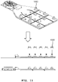
- FIG. 13 is an exemplary view further illustrating a second bent portion 720 in the upper surface and the lower surface of the air duct for a ventilation seat according to an embodiment of the present invention.
- the second bent portion includes: a bead surface that is the upper convex portion 721 configured such that an upper inner surface of the air duct corresponding to the occupant's buttocks at the time of sitting is convex downwardly; and second bent portion that is the lower convex portion 722 configured such that a lower inner surface of the air duct diagonally facing the upper convex portion 721 is convex upwardly.
- the air duct 50 for a ventilation seat can form a wavy air passage, and allows the air flow to smoothly flow to the corners of the air duct while being bent by the occupant's weight at the time of sitting.
- convex beads are provided so that the second bent portion can be flexibly bent at the time of sitting.
- the upper and lower bead surfaces are configured to face each other at the time of sitting, the upper and lower bead surfaces may interfere with the flow path.
- the upper and lower bead surfaces are staggered by at least 5mm, the upper and lower bead surfaces can be flexibly bent without interfering with the flow path.
- FIG. 14 is an exemplary view showing a cross-section of the spacer 130 of the air duct for a ventilation seat according to an embodiment of the present invention.
- the spacer 130 is configured such that the protrusion (boss) functioning as a support is placed in multiple positions to facilitate the formation of the ventilation flow path at the time of seating, which does not affect the flow rate regardless of the positions and the number of protrusions.
Landscapes
- Engineering & Computer Science (AREA)
- Aviation & Aerospace Engineering (AREA)
- Transportation (AREA)
- Mechanical Engineering (AREA)
- Chair Legs, Seat Parts, And Backrests (AREA)
Description
- The present invention relates generally to an air duct for a ventilation seat and a ventilation seat having the same for a vehicle. More particularly, the present invention relates to an air duct for a ventilation seat and a ventilation seat having the same for a vehicle, in which an air flow structure is improved and it is possible to provide a comfortable seating feel to a user.
- An air conditioning apparatus is used to keep the temperature, the humidity, the air cleanliness, and the air flow of a space pleasant, and particularly, the importance of the air conditioning apparatus becomes more prominent in an enclosed space such as a vehicle.
- In general, an air conditioning apparatus applied to a vehicle is provided with a cooling and heating device composed of an air conditioner and a heater to provide air on the front and side of the inside of the vehicle, but a vehicle seat, with which an occupant's body is brought directly into contact, is not provided with the air from the cooling and heating device described above, which is a factor that reduces ride comfort of the occupant.
- Conventionally, as disclosed in
Korean Patent No. 10-1280775 - However, the ventilation seat configured as described above is problematic in that the air transfer hole for guiding air and a fan for sucking air are generally inserted into the seat, which causes discomfort to the occupant when the occupant sits on the seat, so the ride comfort is deteriorated. Further, when the air transfer hole for guiding air is made of a material such as memory foam that absorbs an external force while maintaining a predetermined shape in order to improve the ride comfort, the space defined in the air transfer hole is blocked when an occupant sits on the seat and an external force is applied to the seat, so air may not be smoothly transported.
- Further, in
Korean Patent Application Publication No. 2016-0062237 - Further, the conventional ventilation seat is problematic in that when an external force is applied to the seat by an occupant, the sucked air leaks into a fine gap formed on the seat of the vehicle, so noise may be generated due to the fan under load.
-
- 1.
Korean Patent No. 10-1280775 (registered June 25, 2013 - 2.
Korean Patent Application Publication No. 2016-0062237 (published June 02, 2016 - 3. Korean Patent No.
KR 101 549 826 B1 - 4. Korean Patent No.
KR 101 244 881 B1 - 5. Korean Patent Application No.
KR 2016 0136858 A1 - 6. US Patent Application No.
US 2018/065524 A1 - 7. European Patent Application No.
EP 3 006 262 A1 - Accordingly, the present invention has been made keeping in mind the above problems occurring in the related art, and an object of the present invention is to provide an air duct for a ventilation seat and a ventilation seat having the same for a vehicle, in which it is possible to uniformly discharge sucked air to a seat of a vehicle and to minimize the discomfort experienced by a vehicle occupant, thereby providing a comfortable ride.
- Further, another object of the present invention is to provide an air duct for a ventilation seat and a ventilation seat having the same for a vehicle, in which it is possible to minimize an external force transmitted to a panel provided in a vehicle seat to guide the flow of air, thereby facilitating the air flow and reducing noise.
- In order to achieve the above object, the present invention provides an air duct for a ventilation seat in accordance with claim 1.
- Preferably, the spacer is configured such that protrusions are provided on at least one of the lower surface and the upper surface to extend toward the other surface at predetermined intervals.
- Preferably, the upper surface is configured such that a gentle conical protruding portion is provided on an inner surface thereof facing the air inlet so as to diffuse incoming air to ends of the corners; and the lower surface is fastened by using a fastener to a conveying duct for conveying air from a fan, and includes a locking piece provided to intersect in a U shape with the fastener fastening the conveying duct.
- Preferably, the upper surface or the lower surface includes a wrinkle portion to be bent at a predetermined angle at a time of sitting. Further, a nonwoven fabric may be attached to a bottom of the lower surface.
- Preferably, the upper surface is configured such that a spiral protrusion is provided on an inner side of each of the air outlets.
- Preferably, the air duct constituted by the upper surface and the lower surface is provided with a fan and a conveying duct at a side thereof; and the upper surface or the lower surface includes a bent portion that partitions a flow direction of incoming air and guides air flow. The upper surface or the lower surface may include a first bent portion configured to be bent at a predetermined angle at a time of sitting while partitioning a flow direction of incoming air into at least one of a central portion, a left side, and a right side, and the first bent portion may be configured such that an end thereof is gently curved toward an air inlet side.
- Preferably, the upper surface or the lower surface includes a second bent portion configured to be bent in a direction perpendicular to a flow direction of air flowing in the air duct. The second bent portion may include: an upper convex portion configured such that an upper inner surface of the air duct corresponding to a seat bottom of the upper surface is convex downwardly; and a lower convex portion configured such that an inner surface of the lower surface diagonally facing the upper convex portion is convex upwardly, wherein the upper convex portion and the lower convex portion are spaced apart from each other at a predetermined interval.
- Preferably, the air duct of includes: a lower chamber of hard material configured such that the upper surface is provided with a discharge hole, the lower surface is provided with an air inlet, and the corners of the upper surface and the lower surface are attached together to form a chamber-type air passage; and an adapter of soft material provided with a plurality of air outlets connected with the discharge hole of the lower chamber to be connected to a discharge passage of a foam pad.
- Preferably, a chamber constituted by the upper surface and the lower surface is configured such that a width thereof is gradually increased from an air inlet side toward an inside of the chamber and then is constant.
- Preferably, a ventilation seat is configured in a form of a seat back part or a seat bottom part, the ventilation seat including: the upper surface provided with the plurality of air outlets; the lower surface provided with the air inlet, and configured such that the corners thereof are attached to the corners of the upper surface to form the air passage; the spacer provided on at least one of the lower surface and the upper surface to extend toward the other surface; a cushion part connected to the air outlets of the upper surface and an air passage of the foam pad; and a support means supporting the lower surface.
- According to the present invention, it is possible to uniformly discharge sucked air to the seat of the vehicle and to minimize the discomfort experienced by a vehicle occupant, thereby providing a comfortable ride. The clamping portion has an important technical effect that secures a flow path by stably forming a space between the upper surface and the lower surface, and enables the conveying duct to be stably fixed to the lower surface.
-
-
FIG. 1 is a perspective view showing an upper surface of an air duct for a ventilation seat according to a first embodiment of the present invention. -
FIG. 2 is an exemplary view showing a lower surface of the air duct for a ventilation seat according to the first embodiment of the present invention. -
FIG. 3 is an exemplary view showing a shape of a seat backpart 20 of an air duct for a ventilation seat according to a second embodiment of the present invention. -
FIG. 4 is an inside perspective view showing a seat back part and a seat bottom part of a ventilation seat for a vehicle having the air duct according to the first embodiment and the second embodiment of the present invention. -
FIG. 5 is an exemplary view showing a rear side of the ventilation seat for a vehicle having the air duct according to the first embodiment and the second embodiment of the present invention. -
FIG. 6 is an exemplary view showing a cross-section of the ventilation seat for a vehicle having the air duct according to the first embodiment and the second embodiment of the present invention. -
FIG. 7 is an exemplary view showing a shape of anair duct 50 for a ventilation seat according to a third embodiment of the present invention. -
FIG. 8 is a sectional perspective view showing the shape of theair duct 50 for a ventilation seat according to the third embodiment of the present invention. -
FIG. 9 is a perspective view showing a shape of anair duct 60 for a ventilation seat according to a fourth embodiment of the present invention. -
FIG. 10 is an assembly perspective view showing theair duct 60 for a ventilation seat according to the fourth embodiment of the present invention. -
FIG. 11 is an exemplary view showing acap 1000 of the air duct for a ventilation seat according to an embodiment of the present invention. -
FIG. 12 is an exemplary view showing a cross-section of thecap 1000 of the air duct for a ventilation seat according to an embodiment of the present invention. -
FIG. 13 is an exemplary view further illustrating a secondbent portion 720 in the upper surface and the lower surface of the air duct for a ventilation seat according to an embodiment of the present invention. -
FIG. 14 is an exemplary view showing a cross-section of a spacer of the air duct for a ventilation seat according to an embodiment of the present invention. - Hereinbelow, the present invention will be described in detail with reference to the accompanying drawings. Wherever possible, the same reference numerals will be used throughout the drawings and the description to refer to the same or like elements or parts. Further, it is to be noted that, when the functions of conventional elements and the detailed description of elements related with the present invention may make the gist of the present invention unclear, a detailed description of those elements will be omitted.
-
FIG. 1 is a perspective view showing an upper surface of an air duct for a ventilation seat according to a first embodiment of the present invention, andFIG. 2 is an exemplary view showing a lower surface of the air duct for a ventilation seat according to the first embodiment of the present invention. As shown inFIGS. 1 and2 , anair duct 10 for a ventilation seat according to the embodiment has a chamber-type structure including anupper surface 110, alower surface 120, and aspacer 130. - The
upper surface 110 is formed with a plurality ofair outlets 111. Thelower surface 120 is formed with an air inlet, and corners thereof are attached to corners of the upper surface to form a chamber-type air passage. Thespacer 130 is formed on at least one surface of the lower surface and the upper surface toward the other surface. - A
spiral protrusion 112 is formed on an inner side of theair outlet 111 so as to form a vortex in a discharge passage of a foam pad when theair outlet 111 of theupper surface 110 is coupled to the foam pad of a seat cushion part of the vehicle. With this structure, the discharged air is discharged in a vortex form to increase the strength and pressure of the air flow. Meanwhile,FIG. 11 is an exemplary view showing acap 1000 of the air duct for a ventilation seat according to an embodiment of the present invention, andFIG. 12 is an exemplary view showing a cross-section of thecap 1000 of the air duct for a ventilation seat according to an embodiment of the present invention. As shown inFIGS. 11 and12 , theair outlet 111 of the air duct may be provided with acylindrical cap 1000 on the outer surface thereof to be engaged with the discharge passage of the foam pad, wherein thecap 1000 is formed on the inner side thereof with a threaded protrusion to form a vortex. - As shown in
FIG. 1 , the upper surface is provided with a clampingportion 113 so as to be clamped to clamping means provided on opposite sides of afastener 121 of the lower surface ofFIG. 2 . Accordingly, the space between the upper surface and the lower surface can be stably formed, and stable fixing is possible even when the air duct is fastened to a conveyingduct 300. - Further, as shown in
FIGS. 1 and2 , thespacer 130 of theair duct 10 for a ventilation seat can prevent clogging of the air passage due to the weight of an occupant by forming a plurality of protrusions at predetermined intervals on the inner surface of the corresponding position where the human body is brought in contact at the time of sitting. Theair outlet 111 may be variously designed according to the position of the air passage of the foam pad according to the type of vehicle. - The
air duct 10 for a ventilation seat according to the embodiment is configured such that a gentle conical protruding portion (not shown) is provided on the inner side of the upper surface, which is the inner side of the air duct for a ventilation seat facing the air inlet of the lower surface, thereby diffusing the incoming air to the inner corners of the air duct for a ventilation seat. As shown inFIG. 1 , the bending of one end of theair duct 10 for a ventilation seat may be changed according to the shape of the foam pad. - As shown in
FIG. 2 , the air duct for a ventilation seat is fastened to a conveyingduct 300 for conveying air from afan 200. Herein, theair duct 10 for a ventilation seat includes alocking piece 122 formed at the bottom thereof to intersect with thefastener 121 fastened to the conveyingduct 300 in a U shape. Due to the configuration of thelocking piece 122 formed to intersect in the U shape, the air duct can be fastened by the weight of the foam pad and the seat placed on the upper portion of the air duct without a fastening means, and it is possible to prevent separation due to the vibration of the fan or conveying duct. Further, the conveyingduct 300 is provided with anelastic member 310 that includes a firstelastic member 311 connected to thefan 200 and a secondelastic member 312 connected to the lower surface of the air duct, thereby reducing the vibration transmitted from thefan 200. -
FIG. 3 is an exemplary view showing a shape of a seat backpart 20 of an air duct for a ventilation seat according to a second embodiment of the present invention. As shown inFIG. 3 , the air duct may include awrinkle portion 123 configured such that wrinkles are formed on one surface of an upper surface and a lower surface in a horizontal direction so as to be bent at a predetermined angle at the time of sitting against the seat back part. - Further, a
nonwoven fabric 140 may be attached to the lower surface of theair duct 120 for a ventilation seat to reduce vibration of the fan or the conveying duct. Further, a support means 150 may be provided to support the external force transmitted by the occupant's weight, and preferably, the support means 150 is formed in a shape that is bent at least once so as to disperse and support the transmitted external force. Further, as shown inFIG. 2 , the conveyingduct 300 may be provided with at least oneelastic member 310 to absorb the external force applied thereto. - When the
air duct 120 for a ventilation seat is applied to a vehicle seat, thespiral protrusion 112 is formed on the inner side of theair outlet 111 so as to form a vortex in the discharge passage of the foam pad when theair outlet 111 of theupper surface 110 is coupled to the foam pad of the seat cushion part of the vehicle. Theair outlet 111 of the air duct may be provided with thespiral cap 1000 shown inFIGS. 11 and12 to form a vortex. With this structure, the discharged air is discharged in a vortex form to increase the strength and pressure of the air flow. -
FIG. 4 is an inside perspective view showing a seat back part and a seat bottom part of a ventilation seat for a vehicle having the air duct according to the first embodiment and the second embodiment of the present invention,FIG. 5 is an exemplary view showing a rear side of the ventilation seat for a vehicle having the air duct according to the first embodiment and the second embodiment of the present invention, andFIG. 6 is an exemplary view showing a cross-section of the ventilation seat for a vehicle having the air duct according to the first embodiment and the second embodiment of the present invention. - As shown in
FIG. 4 , a seatbottom part 30 of aventilation seat 400 for a vehicle having an air duct for a ventilation seat includes anair duct 410 for a ventilation seat, a support means 420, and acushion part 430. - The
air duct 410 for a ventilation seat according to the embodiment is provided with awrinkle portion 411 at a position corresponding to the buttocks portion at the time of sitting so as to be bent at the time of sitting. The support means 420 is provided to support the bottom of theair duct 410 for a ventilation seat, and the support means 420 includes anonwoven fabric 421 attached to the bottom of theair duct 410 for a ventilation seat to reduce vibration transmitted from the fan or the conveying duct. Further, thecushion part 430 is configured such that an air passage thereof is connected to theair outlet 412 of theair duct 410 for a ventilation seat to discharge air through aventilation seat hole 431. - Further, a seat back
part 40 of theventilation seat 400 for a vehicle having an air duct for a ventilation seat includes anair duct 440 for a ventilation seat, a support means 450, and acushion part 460. Theair duct 440 for a ventilation seat is formed in the shape of the seat backpart 40, and awrinkle portion 441 is provided at a position corresponding to the back of the occupant at the time of sitting to give comfort. Further, the seat back part is provided with the support means 450 for supporting the back side of theair duct 440 for a ventilation seat, and anonwoven fabric 451 is attached to the rear surface of the support means 450 to reduce vibration transmitted from the fan or the conveying duct. Thecushion part 460 is configured such that an air passage thereof is connected to theair outlet 442 of theair duct 440 for a ventilation seat to discharge air through aventilation seat hole 461. Each of theair outlets FIG. 4 may be provided with the spiral protrusion or a structure of a spiral cap on the inner side thereof, as shown inFIGS. 1 ,11 , and12 . - As shown in
FIG. 5 , theventilation seat 400 for a vehicle having an air duct for a ventilation seat may be provided with at least oneelastic member 310 at the conveyingduct 300 to absorb the external force applied thereto when thefan 200 and the conveyingduct 300 are connected with each other. Theelastic member 310 includes: the firstelastic member 311 formed with wrinkles at a portion of the conveyingduct 300 connected to thefan 200 side; and the secondelastic member 312 formed with wrinkles at a portion of the conveyingduct 300 connected to the air duct side. In addition to the elastic member, the support means 450 and thenonwoven fabric 451 are provided reduce vibration due to seating and vibration transmitted from the fan including the supporting portion and the nonwoven fabric. - As shown in
FIG. 6 , thefan 200 and the conveyingduct 300 may be separately provided and connected to the air ducts of the seat backpart 40 and the seatbottom part 30, or may be integrally provided. Although theventilation seat 400 for a vehicle having theair duct 410 of the seatbottom part 30 and theair duct 440 of the seat backpart 40 has been described with reference to the first and second embodiments, it is of course possible to apply an air duct for a ventilation seat of the embodiment described below. - The seat
bottom part 30 ofFIG. 6 is configured such that theair duct 410, at which thefan 200 and the conveyingduct 300 are connected with each other, is supported by the support means 420, vibration is reduced by theelastic member 310 of the conveyingduct 300, and the nonwoven fabric is provided between the support means 420 and theair duct 410 to reduce vibration. The air outlet of theair duct 410 is connected with the air passage of thecushion part 430 such that air is discharged through theventilation seat hole 431. The seat backpart 40 has been described above with reference toFIG. 4 , and a description thereof will be omitted. -
FIG. 7 is an exemplary view showing a shape of anair duct 50 for a ventilation seat according to a third embodiment of the present invention, andFIG. 8 is a sectional perspective view showing the shape of theair duct 50 for a ventilation seat according to the third embodiment of the present invention. As shown inFIGS. 7 and 8 , thefan 200 and the conveyingduct 300 may be integrally provided at one side of theair duct 50 for a ventilation seat. Further, theair duct 50 for a ventilation seat includes abent portion 700 that partitions or induces the flow direction of the incoming air. Thebent portion 700 includes: a firstbent portion 710 configured to be bent at a predetermined angle at the time of sitting while dividing the flow direction of the air flow into a central portion, a left side, and a right side; and a secondbent portion 720 configured to be bent in a vertical direction based on the flow direction of the air flowing in theair duct 50. - The first
bent portion 710 is configured to be bent at a predetermined angle at the time of sitting while apartition portion 711 in the form of a partition plate or a protrusion divides the direction of the air flow introduced in theair duct 50 into the central portion, the left side, and the right side. The firstbent portion 710 is configured, as shown inFIG. 7 , such that an airinlet side end 712 is gently curved so as to induce the direction of the air flow to the central portion, the left side, and the right side. Further, theair duct 50 for a ventilation seat is formed to be gradually wider from the air inlet side toward the inside and then have a predetermined width, and the end of the first bent portion is gently bent along the appearance of theair duct 50 toward the air inlet side to evenly induce the direction of the air flow by dividing the air duct into the central portion, the left side, and the right side. - The second
bent portion 720 includes: an upperconvex portion 721 configured such that an upper inner surface of the air duct corresponding to the buttocks at the time of sitting is convex downwardly; and a lowerconvex portion 722 configured such that a lower inner surface of the air duct diagonally facing the upperconvex portion 721 is convex upwardly. Due to the secondbent portion 720, theair duct 50 for a ventilation seat can form a wavy air passage, and allows the air flow to smoothly flow to the corners of the air duct while being bent by the occupant's weight at the time of sitting. -
FIG. 8 is a sectional perspective view showing the shape of theair duct 50 for a ventilation seat according to the third embodiment of the present invention, wherein thespacer 130 is provided in the form of a protrusion on either the upper surface or the lower surface. The protrusion of thespacer 130 may be protrudingly provided on each of the inner upper surface and the inner lower surface of the air duct to be connected to each other, or to be spaced apart from each other. The protrusion of thespacer 130 maintains the air passage inside the chamber-type air duct so that air can be discharged to theair outlet 111. The description of the firstbent portion 710 having thepartition portion 711 and the air inlet side end 712 ofFIG. 8 , and the upperconvex portion 721 and the lowerconvex portion 722 of the secondbent portion 720 have been made with reference toFIG. 7 . -
FIG. 9 is a perspective view showing a shape of anair duct 60 for a ventilation seat according to a fourth embodiment of the present invention, andFIG. 10 is an assembly perspective view showing theair duct 60 for a ventilation seat according to the fourth embodiment of the present invention. As shown inFIGS. 9 and10 , theair duct 60 for a ventilation seat according to the fourth embodiment includes alower chamber 910 and anadapter 920. - As shown in
FIG. 10 , thelower chamber 910 is configured such that the upper surface thereof is formed with adischarge hole 911, and the lower surface thereof is formed with an air inlet through which air is introduced from the fan and the conveying duct. Here, the lower chamber of hard material is configured such that the corners of the upper surface and the lower surface are attached together to form the chamber-type air passage, and theadapter 920 of soft material includes a plurality ofair outlets 111 connected with thedischarge hole 911 of thelower chamber 910 to be connected to the discharge passage of the foam pad according to the vehicle model. Further, theadapter 920 is provided with the bent portion described in the above embodiment to induce the air flow and to be bent while forming the air passage, thereby giving comfort at the time of sitting. Here, the spacer may be configured such that a protrusion protrudes downwardly from the upper surface of theadapter 920. - The
lower chamber 910 and theadapter 920 is configured, as shown inFIG. 10 , such that multiple coupling means 912 of thelower chamber 910 and multiple coupling means 921 of theadapter 920 are coupled together to seal the lower chamber and the adapter; and the air has a constant pressure through the discharge hole of the lower chamber in thelower chamber 910 and theadapter 920, and is discharged to theair outlet 111 of the adapter. - Meanwhile, the air duct for a ventilation seat according to an embodiment of the present invention is configured, as shown in
FIG. 10 , such that theair outlet 111 of the air duct is formed on the inner side thereof with thespiral protrusion 112 so as to form a vortex in the discharge passage of the foam pad when theair outlet 111 is coupled to the foam pad of the cushion part. Thespiral cap 1000 may be provided at the adapter or the air outlet of the air to form a vortex. With this structure, the discharged air is discharged in a vortex form to increase the strength and pressure of the air flow. -
FIG. 11 is an exemplary view showing thecap 1000 of the air duct for a ventilation seat according to an embodiment of the present invention, andFIG. 12 is an exemplary view showing a cross-section of thecap 1000 of the air duct for a ventilation seat according to an embodiment of the present invention. As shown inFIG. 11 , thecap 1000 of the air duct is configured such that a capsule-type second air outlet is inserted in and assembled with the air outlet to maximize wind pressure. As shown inFIG. 12 , thecap 1000 is formed with the threaded protrusion that can generate a rotating wind vortex. -
FIG. 13 is an exemplary view further illustrating a secondbent portion 720 in the upper surface and the lower surface of the air duct for a ventilation seat according to an embodiment of the present invention. The second bent portion includes: a bead surface that is the upperconvex portion 721 configured such that an upper inner surface of the air duct corresponding to the occupant's buttocks at the time of sitting is convex downwardly; and second bent portion that is the lowerconvex portion 722 configured such that a lower inner surface of the air duct diagonally facing the upperconvex portion 721 is convex upwardly. Due to the secondbent portion 720, theair duct 50 for a ventilation seat can form a wavy air passage, and allows the air flow to smoothly flow to the corners of the air duct while being bent by the occupant's weight at the time of sitting. As shown inFIG. 13 , convex beads are provided so that the second bent portion can be flexibly bent at the time of sitting. Here, if the upper and lower bead surfaces are configured to face each other at the time of sitting, the upper and lower bead surfaces may interfere with the flow path. However, if the upper and lower bead surfaces are staggered by at least 5mm, the upper and lower bead surfaces can be flexibly bent without interfering with the flow path. -
FIG. 14 is an exemplary view showing a cross-section of thespacer 130 of the air duct for a ventilation seat according to an embodiment of the present invention. As shown inFIG. 14 , thespacer 130 is configured such that the protrusion (boss) functioning as a support is placed in multiple positions to facilitate the formation of the ventilation flow path at the time of seating, which does not affect the flow rate regardless of the positions and the number of protrusions. - Although a preferred embodiment of the present invention has been described for illustrative purposes, those skilled in the art will appreciate that various modifications, additions and substitutions are possible, if not thereby departing from the scope of the invention as disclosed in the accompanying claims.
Claims (17)
- An air duct (10) for a ventilation seat, comprising: an upper surface (110) provided with a plurality of air outlets (111); and a lower surface (120) provided with an air inlet, and configured such that corners thereof are attached to corners of the upper surface (110) to form an air passage,
wherein the air duct (10) comprises a spacer (130) provided on at least one of the lower surface (120) and the upper surface (110) to extend toward the other surface; and a clamping portion (113) provided on the upper surface (110) which is coupled by clamping to clamping means provided on the lower surface (120). - . An air duct (10) according to claim 1, wherein the spacer (130) is configured such that protrusions are provided on at least one of the lower surface (120) and the upper surface (110) to extend toward the other surface at predetermined intervals.
- . An air duct (10) according to claim 1, wherein the upper surface (110) is configured such that a gentle conical protruding portion is provided on an inner surface thereof facing the air inlet so as to diffuse incoming air to ends of the corners.
- . An air duct (10) according tc claim 1, wherein the lower surface (120) is fastened by using a fastener to a conveying duct (300) for conveying air from a fan (200), and comprises a locking piece provided to intersect in a U shape with the fastener fastening the conveying duct (300).
- . An air duct (10) according tc claim 1, wherein the upper surface (110) or the lower surface comprises a wrinkle portion (123,441) to be bent at a predetermined angle at a time of sitting.
- . An air duct (10) according to claim 1, wherein the upper surface (110) is configured such that a spiral protrusion is provided on an inner side of each of the air outlets (111).
- . An air duct (10) according to claim 1, wherein the upper surface (110) is configured such that a spiral cap (1000) is coupled to each of the air outlets (111).
- . An air duct (10) according to claim 1, wherein the air duct (10) constituted by the upper surface (110) and the lower surface (120) is provided with a fan (200) and a conveying duct (300) at a side thereof.
- . An air duct (10) according to claim 1, wherein the upper surface (110) or the lower surface (120) comprises a bent portion (700) that partitions a flow direction of incoming air and guides air flow.
- An air duct (10) according to claim 1, wherein the upper surface (110) or the lower surface (120) comprises a first bent portion (710) configured to be bent at a predetermined angle at a time of sitting while partitioning a flow direction of incoming air into at least one of a central portion, a left side, and a right side.
- . An air duct (10) according to claim 10,
wherein the first bent portion (710) is configured such that an end thereof is gently curved toward an air inlet side. - . An air duct (10) according to claim 1, wherein the upper surface (110) or the lower surface (120) comprises a second bent portion (720) configured to be bent in a direction perpendicular to a flow direction of air flowing in the air duct.
- . An air duct (10) according to claim 12,
wherein the second bent portion (720) comprises:an upper convex portion (721) configured such that an upper inner surface of the air duct (10) corresponding to a seat bottom of the upper surface (110) is convex downwardly; anda lower convex portion (722) configured such that an inner surface of the lower surface (120) diagonally facing the upper convex portion (721) is convex upwardly,wherein the upper convex portion (721) and the lower convex portion (722) are spaced apart from each other at a predetermined interval. - . An air duct (10) according to claim 1, wherein the air duct (10) further comprisesa lower chamber (910) of hard material configured such that the upper surface (110) is provided with a discharge hole (911), the lower surface (120) is provided with an air inlet, and the corners of the upper surface (110) and the lower surface (120) are attached together to form a chamber-type air passage; andan adapter (920) of soft material provided with a plurality of air outlets (911) connected with the discharge hole (911) of the lower chamber (910) to be connected to a discharge passage of a foam pad.
- . An air duct (10) according to claim 1, wherein a chamber constituted by the upper surface (110) and the lower surface (120) is configured such that a width thereof is gradually increased from an air inlet side toward an inside of the chamber and then is constant.
- . A ventilation seat configured in a form of a seat back part or a seat bottom part, the ventilation seat comprising an air duct for a ventilation seat according to claim 1.
- . A ventilation seat according to claim 16, comprising a support means (150, 420, 450) for supporting a bottom of the lower surface (120) of the air duct (10), and the support means (150, 420, 450) comprising a nonwoven fabric (140) attached to the bottom of the lower surface (120) of the air duct (10).
Applications Claiming Priority (3)
| Application Number | Priority Date | Filing Date | Title |
|---|---|---|---|
| KR1020180049911A KR20190125732A (en) | 2018-04-30 | 2018-04-30 | Ventilation seat apparatus for vehicle having adapter structure |
| KR1020180049912A KR20190125733A (en) | 2018-04-30 | 2018-04-30 | Ventilation seat apparatus for vehicle having bent portion of vertical structure |
| PCT/KR2019/001275 WO2019212124A1 (en) | 2018-04-30 | 2019-01-30 | Air duct for ventilation seat and vehicle ventilation seat having same |
Publications (3)
| Publication Number | Publication Date |
|---|---|
| EP3632740A1 EP3632740A1 (en) | 2020-04-08 |
| EP3632740A4 EP3632740A4 (en) | 2021-02-17 |
| EP3632740B1 true EP3632740B1 (en) | 2022-06-15 |
Family
ID=68386556
Family Applications (1)
| Application Number | Title | Priority Date | Filing Date |
|---|---|---|---|
| EP19786895.3A Active EP3632740B1 (en) | 2018-04-30 | 2019-01-30 | Air duct for ventilation seat and vehicle ventilation seat having same |
Country Status (4)
| Country | Link |
|---|---|
| US (1) | US11433790B2 (en) |
| EP (1) | EP3632740B1 (en) |
| CN (1) | CN110662670B (en) |
| WO (1) | WO2019212124A1 (en) |
Families Citing this family (5)
| Publication number | Priority date | Publication date | Assignee | Title |
|---|---|---|---|---|
| DE112020006246T5 (en) * | 2019-12-20 | 2022-09-29 | Gentherm Incorporated | Vehicle seat air distribution device |
| CN116133894B (en) | 2020-06-29 | 2025-09-09 | 普罗普里特公司 | Ventilated seat assembly |
| CN114056203A (en) * | 2020-08-03 | 2022-02-18 | 捷温有限责任公司 | Air flow generating device for ventilating a vehicle seat and vehicle seat |
| DE102020213641A1 (en) * | 2020-10-29 | 2022-05-05 | Ford Global Technologies, Llc | Seat structure for a vehicle seat and vehicle seat |
| US20240010107A1 (en) * | 2020-12-07 | 2024-01-11 | Youngmin Hightech Co., Ltd. | Neck vent provision structure for ventilated seat of vehicle |
Family Cites Families (36)
| Publication number | Priority date | Publication date | Assignee | Title |
|---|---|---|---|---|
| US5626382A (en) * | 1995-04-03 | 1997-05-06 | Lear Corporation | Molded plastic panel having integrated, localized soft-touch aesthetic feature |
| US6179706B1 (en) * | 1998-06-19 | 2001-01-30 | Denso Corporation | Seat air conditioner for vehicle |
| FR2790430B1 (en) * | 1999-03-01 | 2001-05-18 | Faure Bertrand Equipements Sa | VEHICLE SEAT THERMAL REGULATION METHOD AND SYSTEM |
| DE10351805A1 (en) * | 2002-11-08 | 2004-05-27 | Denso Corp., Kariya | Motor vehicle seat air conditioning system has buffer element between upholstery element and air outlet channel that dampens vibrations of ventilator unit |
| JP4013765B2 (en) * | 2003-01-14 | 2007-11-28 | 株式会社デンソー | Vehicle seat air conditioner |
| DE50300806D1 (en) * | 2003-03-06 | 2005-08-25 | Gore W L & Ass Gmbh | Air conditioning system for cooling and heating surfaces, in particular car seats |
| US7114771B2 (en) * | 2004-05-25 | 2006-10-03 | Amerigon, Inc. | Climate controlled seat |
| US7478869B2 (en) | 2005-08-19 | 2009-01-20 | W.E.T. Automotive Systems, Ag | Automotive vehicle seat insert |
| US20090033130A1 (en) * | 2007-07-02 | 2009-02-05 | David Marquette | Fluid delivery systems for climate controlled seats |
| JP2010162935A (en) * | 2009-01-13 | 2010-07-29 | Toyota Boshoku Corp | Vehicular seat |
| US20110260509A1 (en) * | 2009-05-22 | 2011-10-27 | Siu David S K | Structurally improved seat cushion |
| US9055820B2 (en) * | 2009-11-12 | 2015-06-16 | Igb Automotive Ltd. | Air manifold for ventilated seat or bed |
| JP2013023003A (en) * | 2011-07-19 | 2013-02-04 | Toyota Boshoku Corp | Vehicle seat |
| KR101280775B1 (en) | 2011-11-21 | 2013-07-05 | 현대다이모스(주) | Ventilating seat for vehicle |
| KR101180702B1 (en) | 2012-03-07 | 2012-09-07 | (주)광진윈텍 | A Seat for the Vehicle |
| KR101244881B1 (en) | 2012-11-19 | 2013-03-19 | 조동연 | A seat for the vehicle |
| BR112015013044B1 (en) * | 2012-12-05 | 2021-06-01 | Proprietect L.P. | VEHICLE SEAT ELEMENT |
| US8960791B2 (en) * | 2013-07-02 | 2015-02-24 | Ford Global Technologies, Llc | Trim attachment apparatus for vehicle seating assembly |
| DE202013006135U1 (en) * | 2013-07-09 | 2013-07-25 | I.G. Bauerhin Gmbh | Air conditioning device for a vehicle seat |
| US9315131B2 (en) * | 2014-01-23 | 2016-04-19 | Ford Global Technologies, Llc | Suspension seat back and cushion system having an inner suspension panel |
| KR101549826B1 (en) * | 2014-03-04 | 2015-09-03 | 대원산업 주식회사 | Cushion pad having ventilation mat |
| EP3147156B1 (en) * | 2014-05-23 | 2019-08-07 | Dayou Holdings Co., Ltd. | Multi-hardness cushion for automobile and multi-hardness cushion having ventilation structure |
| KR101683484B1 (en) | 2015-05-21 | 2016-12-07 | 주식회사 동강홀딩스 | A ventilated pad for vehicle |
| EP3006262B1 (en) | 2014-10-07 | 2016-11-23 | C.R.F. Società Consortile per Azioni | Motor-vehicle seat provided with a system for supplying conditioned air |
| KR101637704B1 (en) * | 2014-10-28 | 2016-07-07 | 현대자동차주식회사 | Ventilation seat for vehicle |
| KR101641914B1 (en) | 2014-11-24 | 2016-07-26 | 대원강업주식회사 | Vehicle seat using seat foam pad integrated type ventilation system |
| DE202014009326U1 (en) * | 2014-11-25 | 2016-02-26 | I.G. Bauerhin Gmbh | Vehicle seat with an air conditioning device |
| KR101662786B1 (en) | 2014-12-30 | 2016-10-06 | 갑을오토텍(주) | Ventilation seat |
| CN107249931B (en) * | 2015-02-13 | 2020-07-14 | 株式会社塔捷斯 | vehicle seat |
| JP6582068B2 (en) * | 2015-07-21 | 2019-09-25 | ジェンサーム オートモーティブ システムズ チャイナリミテッド | Connector for temperature-controlled support device |
| US10279714B2 (en) * | 2016-08-26 | 2019-05-07 | Ford Global Technologies, Llc | Seating assembly with climate control features |
| DE202016005441U1 (en) | 2016-09-07 | 2017-12-08 | l. G. Bauerhin GmbH | vehicle seat |
| DE102017213484B4 (en) * | 2017-08-03 | 2021-07-15 | Lear Corporation | Seat assembly and method of forming a seat assembly |
| WO2019112823A1 (en) * | 2017-12-07 | 2019-06-13 | Gentherm Incorporated | Conditioning system with a b-side distribution system |
| US11318869B2 (en) * | 2018-12-06 | 2022-05-03 | Gentherm Incorporated | Single piece plenum |
| US10919422B2 (en) * | 2019-02-27 | 2021-02-16 | Faurecia Automotive Seating, Llc | Ventilated seat |
-
2019
- 2019-01-30 CN CN201980002070.1A patent/CN110662670B/en active Active
- 2019-01-30 WO PCT/KR2019/001275 patent/WO2019212124A1/en not_active Ceased
- 2019-01-30 US US16/499,409 patent/US11433790B2/en active Active
- 2019-01-30 EP EP19786895.3A patent/EP3632740B1/en active Active
Also Published As
| Publication number | Publication date |
|---|---|
| CN110662670A (en) | 2020-01-07 |
| WO2019212124A1 (en) | 2019-11-07 |
| EP3632740A4 (en) | 2021-02-17 |
| US20210402899A1 (en) | 2021-12-30 |
| US11433790B2 (en) | 2022-09-06 |
| CN110662670B (en) | 2022-07-05 |
| EP3632740A1 (en) | 2020-04-08 |
Similar Documents
| Publication | Publication Date | Title |
|---|---|---|
| EP3632740B1 (en) | Air duct for ventilation seat and vehicle ventilation seat having same | |
| JP5103114B2 (en) | Air conditioning sheet | |
| JP3786701B2 (en) | Device for ventilating vehicle chairs | |
| US5927817A (en) | Ventilated vehicle seat assembly | |
| US6145925A (en) | Backrest for vehicle seats | |
| US6848742B1 (en) | Seat air conditioning unit for vehicle and fan combination of blower units of the same | |
| KR20110051692A (en) | Car seat for cooling and heating | |
| KR101662786B1 (en) | Ventilation seat | |
| BR112019017315B1 (en) | VEHICLE SEAT | |
| KR101244881B1 (en) | A seat for the vehicle | |
| WO2005115794A9 (en) | Climate controlled seat | |
| KR101984728B1 (en) | Ventilation seat apparatus for vehicle | |
| CN106470872A (en) | Many hardness liner for automobile and many hardness liner with aeration structure | |
| US11110773B2 (en) | Seat air-conditioning device | |
| CN105711455B (en) | Distance piece, air guiding device and seat-assembly | |
| US20150329026A1 (en) | Heating, Ventilation, and Air Conditioning Seat Assembly | |
| KR20190125784A (en) | Ventilation seat apparatus for vehicle having bent portion of horizontal structure | |
| US20060038432A1 (en) | Vehicle seat | |
| EP3677457A1 (en) | Blower device for rear seat | |
| KR200485005Y1 (en) | Ventilating seat for vehicle | |
| KR101667797B1 (en) | Ventilation seat | |
| JPH09108070A (en) | Air blowing device for seat | |
| KR20150113227A (en) | The ventilation system in the vehicle seat | |
| KR20190057194A (en) | Chair ventilation and heating | |
| CN204236295U (en) | Spacers, air guides and seat components |
Legal Events
| Date | Code | Title | Description |
|---|---|---|---|
| STAA | Information on the status of an ep patent application or granted ep patent |
Free format text: STATUS: UNKNOWN |
|
| STAA | Information on the status of an ep patent application or granted ep patent |
Free format text: STATUS: THE INTERNATIONAL PUBLICATION HAS BEEN MADE |
|
| PUAI | Public reference made under article 153(3) epc to a published international application that has entered the european phase |
Free format text: ORIGINAL CODE: 0009012 |
|
| STAA | Information on the status of an ep patent application or granted ep patent |
Free format text: STATUS: REQUEST FOR EXAMINATION WAS MADE |
|
| 17P | Request for examination filed |
Effective date: 20191024 |
|
| AK | Designated contracting states |
Kind code of ref document: A1 Designated state(s): AL AT BE BG CH CY CZ DE DK EE ES FI FR GB GR HR HU IE IS IT LI LT LU LV MC MK MT NL NO PL PT RO RS SE SI SK SM TR |
|
| AX | Request for extension of the european patent |
Extension state: BA ME |
|
| A4 | Supplementary search report drawn up and despatched |
Effective date: 20210115 |
|
| RIC1 | Information provided on ipc code assigned before grant |
Ipc: B60N 2/56 20060101AFI20210111BHEP Ipc: A47C 7/74 20060101ALI20210111BHEP |
|
| DAV | Request for validation of the european patent (deleted) | ||
| DAX | Request for extension of the european patent (deleted) | ||
| RIN1 | Information on inventor provided before grant (corrected) |
Inventor name: NOH, KI-YEONG |
|
| GRAP | Despatch of communication of intention to grant a patent |
Free format text: ORIGINAL CODE: EPIDOSNIGR1 |
|
| STAA | Information on the status of an ep patent application or granted ep patent |
Free format text: STATUS: GRANT OF PATENT IS INTENDED |
|
| INTG | Intention to grant announced |
Effective date: 20220103 |
|
| GRAS | Grant fee paid |
Free format text: ORIGINAL CODE: EPIDOSNIGR3 |
|
| GRAA | (expected) grant |
Free format text: ORIGINAL CODE: 0009210 |
|
| STAA | Information on the status of an ep patent application or granted ep patent |
Free format text: STATUS: THE PATENT HAS BEEN GRANTED |
|
| AK | Designated contracting states |
Kind code of ref document: B1 Designated state(s): AL AT BE BG CH CY CZ DE DK EE ES FI FR GB GR HR HU IE IS IT LI LT LU LV MC MK MT NL NO PL PT RO RS SE SI SK SM TR |
|
| REG | Reference to a national code |
Ref country code: CH Ref legal event code: EP Ref country code: GB Ref legal event code: FG4D |
|
| REG | Reference to a national code |
Ref country code: IE Ref legal event code: FG4D |
|
| REG | Reference to a national code |
Ref country code: DE Ref legal event code: R096 Ref document number: 602019015995 Country of ref document: DE |
|
| REG | Reference to a national code |
Ref country code: AT Ref legal event code: REF Ref document number: 1498192 Country of ref document: AT Kind code of ref document: T Effective date: 20220715 |
|
| REG | Reference to a national code |
Ref country code: NL Ref legal event code: FP |
|
| REG | Reference to a national code |
Ref country code: LT Ref legal event code: MG9D |
|
| PG25 | Lapsed in a contracting state [announced via postgrant information from national office to epo] |
Ref country code: SE Free format text: LAPSE BECAUSE OF FAILURE TO SUBMIT A TRANSLATION OF THE DESCRIPTION OR TO PAY THE FEE WITHIN THE PRESCRIBED TIME-LIMIT Effective date: 20220615 Ref country code: NO Free format text: LAPSE BECAUSE OF FAILURE TO SUBMIT A TRANSLATION OF THE DESCRIPTION OR TO PAY THE FEE WITHIN THE PRESCRIBED TIME-LIMIT Effective date: 20220915 Ref country code: LT Free format text: LAPSE BECAUSE OF FAILURE TO SUBMIT A TRANSLATION OF THE DESCRIPTION OR TO PAY THE FEE WITHIN THE PRESCRIBED TIME-LIMIT Effective date: 20220615 Ref country code: HR Free format text: LAPSE BECAUSE OF FAILURE TO SUBMIT A TRANSLATION OF THE DESCRIPTION OR TO PAY THE FEE WITHIN THE PRESCRIBED TIME-LIMIT Effective date: 20220615 Ref country code: GR Free format text: LAPSE BECAUSE OF FAILURE TO SUBMIT A TRANSLATION OF THE DESCRIPTION OR TO PAY THE FEE WITHIN THE PRESCRIBED TIME-LIMIT Effective date: 20220916 Ref country code: FI Free format text: LAPSE BECAUSE OF FAILURE TO SUBMIT A TRANSLATION OF THE DESCRIPTION OR TO PAY THE FEE WITHIN THE PRESCRIBED TIME-LIMIT Effective date: 20220615 Ref country code: BG Free format text: LAPSE BECAUSE OF FAILURE TO SUBMIT A TRANSLATION OF THE DESCRIPTION OR TO PAY THE FEE WITHIN THE PRESCRIBED TIME-LIMIT Effective date: 20220915 |
|
| REG | Reference to a national code |
Ref country code: AT Ref legal event code: MK05 Ref document number: 1498192 Country of ref document: AT Kind code of ref document: T Effective date: 20220615 |
|
| PG25 | Lapsed in a contracting state [announced via postgrant information from national office to epo] |
Ref country code: RS Free format text: LAPSE BECAUSE OF FAILURE TO SUBMIT A TRANSLATION OF THE DESCRIPTION OR TO PAY THE FEE WITHIN THE PRESCRIBED TIME-LIMIT Effective date: 20220615 Ref country code: LV Free format text: LAPSE BECAUSE OF FAILURE TO SUBMIT A TRANSLATION OF THE DESCRIPTION OR TO PAY THE FEE WITHIN THE PRESCRIBED TIME-LIMIT Effective date: 20220615 |
|
| PG25 | Lapsed in a contracting state [announced via postgrant information from national office to epo] |
Ref country code: SM Free format text: LAPSE BECAUSE OF FAILURE TO SUBMIT A TRANSLATION OF THE DESCRIPTION OR TO PAY THE FEE WITHIN THE PRESCRIBED TIME-LIMIT Effective date: 20220615 Ref country code: SK Free format text: LAPSE BECAUSE OF FAILURE TO SUBMIT A TRANSLATION OF THE DESCRIPTION OR TO PAY THE FEE WITHIN THE PRESCRIBED TIME-LIMIT Effective date: 20220615 Ref country code: RO Free format text: LAPSE BECAUSE OF FAILURE TO SUBMIT A TRANSLATION OF THE DESCRIPTION OR TO PAY THE FEE WITHIN THE PRESCRIBED TIME-LIMIT Effective date: 20220615 Ref country code: PT Free format text: LAPSE BECAUSE OF FAILURE TO SUBMIT A TRANSLATION OF THE DESCRIPTION OR TO PAY THE FEE WITHIN THE PRESCRIBED TIME-LIMIT Effective date: 20221017 Ref country code: ES Free format text: LAPSE BECAUSE OF FAILURE TO SUBMIT A TRANSLATION OF THE DESCRIPTION OR TO PAY THE FEE WITHIN THE PRESCRIBED TIME-LIMIT Effective date: 20220615 Ref country code: EE Free format text: LAPSE BECAUSE OF FAILURE TO SUBMIT A TRANSLATION OF THE DESCRIPTION OR TO PAY THE FEE WITHIN THE PRESCRIBED TIME-LIMIT Effective date: 20220615 Ref country code: CZ Free format text: LAPSE BECAUSE OF FAILURE TO SUBMIT A TRANSLATION OF THE DESCRIPTION OR TO PAY THE FEE WITHIN THE PRESCRIBED TIME-LIMIT Effective date: 20220615 Ref country code: AT Free format text: LAPSE BECAUSE OF FAILURE TO SUBMIT A TRANSLATION OF THE DESCRIPTION OR TO PAY THE FEE WITHIN THE PRESCRIBED TIME-LIMIT Effective date: 20220615 |
|
| PG25 | Lapsed in a contracting state [announced via postgrant information from national office to epo] |
Ref country code: PL Free format text: LAPSE BECAUSE OF FAILURE TO SUBMIT A TRANSLATION OF THE DESCRIPTION OR TO PAY THE FEE WITHIN THE PRESCRIBED TIME-LIMIT Effective date: 20220615 Ref country code: IS Free format text: LAPSE BECAUSE OF FAILURE TO SUBMIT A TRANSLATION OF THE DESCRIPTION OR TO PAY THE FEE WITHIN THE PRESCRIBED TIME-LIMIT Effective date: 20221015 |
|
| REG | Reference to a national code |
Ref country code: DE Ref legal event code: R097 Ref document number: 602019015995 Country of ref document: DE |
|
| PG25 | Lapsed in a contracting state [announced via postgrant information from national office to epo] |
Ref country code: AL Free format text: LAPSE BECAUSE OF FAILURE TO SUBMIT A TRANSLATION OF THE DESCRIPTION OR TO PAY THE FEE WITHIN THE PRESCRIBED TIME-LIMIT Effective date: 20220615 |
|
| PLBE | No opposition filed within time limit |
Free format text: ORIGINAL CODE: 0009261 |
|
| STAA | Information on the status of an ep patent application or granted ep patent |
Free format text: STATUS: NO OPPOSITION FILED WITHIN TIME LIMIT |
|
| PG25 | Lapsed in a contracting state [announced via postgrant information from national office to epo] |
Ref country code: DK Free format text: LAPSE BECAUSE OF FAILURE TO SUBMIT A TRANSLATION OF THE DESCRIPTION OR TO PAY THE FEE WITHIN THE PRESCRIBED TIME-LIMIT Effective date: 20220615 |
|
| 26N | No opposition filed |
Effective date: 20230316 |
|
| PG25 | Lapsed in a contracting state [announced via postgrant information from national office to epo] |
Ref country code: SI Free format text: LAPSE BECAUSE OF FAILURE TO SUBMIT A TRANSLATION OF THE DESCRIPTION OR TO PAY THE FEE WITHIN THE PRESCRIBED TIME-LIMIT Effective date: 20220615 |
|
| REG | Reference to a national code |
Ref country code: CH Ref legal event code: PL |
|
| GBPC | Gb: european patent ceased through non-payment of renewal fee |
Effective date: 20230130 |
|
| PG25 | Lapsed in a contracting state [announced via postgrant information from national office to epo] |
Ref country code: LU Free format text: LAPSE BECAUSE OF NON-PAYMENT OF DUE FEES Effective date: 20230130 |
|
| REG | Reference to a national code |
Ref country code: BE Ref legal event code: MM Effective date: 20230131 |
|
| PG25 | Lapsed in a contracting state [announced via postgrant information from national office to epo] |
Ref country code: LI Free format text: LAPSE BECAUSE OF NON-PAYMENT OF DUE FEES Effective date: 20230131 Ref country code: GB Free format text: LAPSE BECAUSE OF NON-PAYMENT OF DUE FEES Effective date: 20230130 Ref country code: CH Free format text: LAPSE BECAUSE OF NON-PAYMENT OF DUE FEES Effective date: 20230131 |
|
| PG25 | Lapsed in a contracting state [announced via postgrant information from national office to epo] |
Ref country code: BE Free format text: LAPSE BECAUSE OF NON-PAYMENT OF DUE FEES Effective date: 20230131 |
|
| PG25 | Lapsed in a contracting state [announced via postgrant information from national office to epo] |
Ref country code: IT Free format text: LAPSE BECAUSE OF FAILURE TO SUBMIT A TRANSLATION OF THE DESCRIPTION OR TO PAY THE FEE WITHIN THE PRESCRIBED TIME-LIMIT Effective date: 20220615 Ref country code: IE Free format text: LAPSE BECAUSE OF NON-PAYMENT OF DUE FEES Effective date: 20230130 |
|
| PG25 | Lapsed in a contracting state [announced via postgrant information from national office to epo] |
Ref country code: MC Free format text: LAPSE BECAUSE OF FAILURE TO SUBMIT A TRANSLATION OF THE DESCRIPTION OR TO PAY THE FEE WITHIN THE PRESCRIBED TIME-LIMIT Effective date: 20220615 |
|
| PG25 | Lapsed in a contracting state [announced via postgrant information from national office to epo] |
Ref country code: MC Free format text: LAPSE BECAUSE OF FAILURE TO SUBMIT A TRANSLATION OF THE DESCRIPTION OR TO PAY THE FEE WITHIN THE PRESCRIBED TIME-LIMIT Effective date: 20220615 |
|
| PG25 | Lapsed in a contracting state [announced via postgrant information from national office to epo] |
Ref country code: BG Free format text: LAPSE BECAUSE OF FAILURE TO SUBMIT A TRANSLATION OF THE DESCRIPTION OR TO PAY THE FEE WITHIN THE PRESCRIBED TIME-LIMIT Effective date: 20220615 |
|
| PG25 | Lapsed in a contracting state [announced via postgrant information from national office to epo] |
Ref country code: BG Free format text: LAPSE BECAUSE OF FAILURE TO SUBMIT A TRANSLATION OF THE DESCRIPTION OR TO PAY THE FEE WITHIN THE PRESCRIBED TIME-LIMIT Effective date: 20220615 |
|
| PG25 | Lapsed in a contracting state [announced via postgrant information from national office to epo] |
Ref country code: CY Free format text: LAPSE BECAUSE OF FAILURE TO SUBMIT A TRANSLATION OF THE DESCRIPTION OR TO PAY THE FEE WITHIN THE PRESCRIBED TIME-LIMIT; INVALID AB INITIO Effective date: 20190130 |
|
| PG25 | Lapsed in a contracting state [announced via postgrant information from national office to epo] |
Ref country code: HU Free format text: LAPSE BECAUSE OF FAILURE TO SUBMIT A TRANSLATION OF THE DESCRIPTION OR TO PAY THE FEE WITHIN THE PRESCRIBED TIME-LIMIT; INVALID AB INITIO Effective date: 20190130 |
|
| PG25 | Lapsed in a contracting state [announced via postgrant information from national office to epo] |
Ref country code: TR Free format text: LAPSE BECAUSE OF FAILURE TO SUBMIT A TRANSLATION OF THE DESCRIPTION OR TO PAY THE FEE WITHIN THE PRESCRIBED TIME-LIMIT Effective date: 20220615 |
|
| PGFP | Annual fee paid to national office [announced via postgrant information from national office to epo] |
Ref country code: NL Payment date: 20260128 Year of fee payment: 8 |
|
| PGFP | Annual fee paid to national office [announced via postgrant information from national office to epo] |
Ref country code: DE Payment date: 20260121 Year of fee payment: 8 |
|
| PGFP | Annual fee paid to national office [announced via postgrant information from national office to epo] |
Ref country code: FR Payment date: 20260121 Year of fee payment: 8 |