EP3632707B1 - Tire and tire manufacturing method - Google Patents
Tire and tire manufacturing method Download PDFInfo
- Publication number
- EP3632707B1 EP3632707B1 EP19200349.9A EP19200349A EP3632707B1 EP 3632707 B1 EP3632707 B1 EP 3632707B1 EP 19200349 A EP19200349 A EP 19200349A EP 3632707 B1 EP3632707 B1 EP 3632707B1
- Authority
- EP
- European Patent Office
- Prior art keywords
- tire
- rubber
- rubber sheet
- rfid tag
- pad
- Prior art date
- Legal status (The legal status is an assumption and is not a legal conclusion. Google has not performed a legal analysis and makes no representation as to the accuracy of the status listed.)
- Active
Links
- 238000004519 manufacturing process Methods 0.000 title claims description 18
- 229920001971 elastomer Polymers 0.000 claims description 266
- 239000011324 bead Substances 0.000 claims description 109
- 239000000945 filler Substances 0.000 claims description 72
- 238000000034 method Methods 0.000 claims description 7
- 230000002787 reinforcement Effects 0.000 claims description 7
- 230000001681 protective effect Effects 0.000 description 28
- 229910000831 Steel Inorganic materials 0.000 description 25
- 239000010959 steel Substances 0.000 description 25
- 239000000835 fiber Substances 0.000 description 16
- 241000254043 Melolonthinae Species 0.000 description 13
- 238000004073 vulcanization Methods 0.000 description 8
- 238000004891 communication Methods 0.000 description 6
- 230000000694 effects Effects 0.000 description 5
- 239000002184 metal Substances 0.000 description 5
- 230000001070 adhesive effect Effects 0.000 description 4
- 239000000126 substance Substances 0.000 description 4
- 239000000470 constituent Substances 0.000 description 3
- 239000004952 Polyamide Substances 0.000 description 2
- 206010052428 Wound Diseases 0.000 description 2
- 208000027418 Wounds and injury Diseases 0.000 description 2
- 239000000853 adhesive Substances 0.000 description 2
- 230000007423 decrease Effects 0.000 description 2
- 238000009826 distribution Methods 0.000 description 2
- 230000001747 exhibiting effect Effects 0.000 description 2
- 239000000463 material Substances 0.000 description 2
- 230000000116 mitigating effect Effects 0.000 description 2
- 229920002647 polyamide Polymers 0.000 description 2
- 238000004088 simulation Methods 0.000 description 2
- PNEYBMLMFCGWSK-UHFFFAOYSA-N aluminium oxide Inorganic materials [O-2].[O-2].[O-2].[Al+3].[Al+3] PNEYBMLMFCGWSK-UHFFFAOYSA-N 0.000 description 1
- 239000004760 aramid Substances 0.000 description 1
- 229920003235 aromatic polyamide Polymers 0.000 description 1
- 239000012298 atmosphere Substances 0.000 description 1
- 239000001913 cellulose Substances 0.000 description 1
- 229920002678 cellulose Polymers 0.000 description 1
- 239000000919 ceramic Substances 0.000 description 1
- 239000003795 chemical substances by application Substances 0.000 description 1
- 239000011248 coating agent Substances 0.000 description 1
- 238000000576 coating method Methods 0.000 description 1
- 239000012141 concentrate Substances 0.000 description 1
- 238000005516 engineering process Methods 0.000 description 1
- 230000002349 favourable effect Effects 0.000 description 1
- -1 for example Polymers 0.000 description 1
- 239000011521 glass Substances 0.000 description 1
- 230000020169 heat generation Effects 0.000 description 1
- 230000002093 peripheral effect Effects 0.000 description 1
- 229920000728 polyester Polymers 0.000 description 1
- 229920006149 polyester-amide block copolymer Polymers 0.000 description 1
- 238000004382 potting Methods 0.000 description 1
- 238000007639 printing Methods 0.000 description 1
- 238000003860 storage Methods 0.000 description 1
- 239000000758 substrate Substances 0.000 description 1
- 239000004636 vulcanized rubber Substances 0.000 description 1
Images


Classifications
-
- B—PERFORMING OPERATIONS; TRANSPORTING
- B60—VEHICLES IN GENERAL
- B60C—VEHICLE TYRES; TYRE INFLATION; TYRE CHANGING; CONNECTING VALVES TO INFLATABLE ELASTIC BODIES IN GENERAL; DEVICES OR ARRANGEMENTS RELATED TO TYRES
- B60C19/00—Tyre parts or constructions not otherwise provided for
-
- B—PERFORMING OPERATIONS; TRANSPORTING
- B60—VEHICLES IN GENERAL
- B60C—VEHICLE TYRES; TYRE INFLATION; TYRE CHANGING; CONNECTING VALVES TO INFLATABLE ELASTIC BODIES IN GENERAL; DEVICES OR ARRANGEMENTS RELATED TO TYRES
- B60C15/00—Tyre beads, e.g. ply turn-up or overlap
- B60C15/06—Flipper strips, fillers, or chafing strips and reinforcing layers for the construction of the bead
- B60C15/0603—Flipper strips, fillers, or chafing strips and reinforcing layers for the construction of the bead characterised by features of the bead filler or apex
- B60C15/0607—Flipper strips, fillers, or chafing strips and reinforcing layers for the construction of the bead characterised by features of the bead filler or apex comprising several parts, e.g. made of different rubbers
-
- B—PERFORMING OPERATIONS; TRANSPORTING
- B60—VEHICLES IN GENERAL
- B60C—VEHICLE TYRES; TYRE INFLATION; TYRE CHANGING; CONNECTING VALVES TO INFLATABLE ELASTIC BODIES IN GENERAL; DEVICES OR ARRANGEMENTS RELATED TO TYRES
- B60C15/00—Tyre beads, e.g. ply turn-up or overlap
- B60C15/06—Flipper strips, fillers, or chafing strips and reinforcing layers for the construction of the bead
- B60C15/0628—Flipper strips, fillers, or chafing strips and reinforcing layers for the construction of the bead comprising a bead reinforcing layer
-
- B—PERFORMING OPERATIONS; TRANSPORTING
- B29—WORKING OF PLASTICS; WORKING OF SUBSTANCES IN A PLASTIC STATE IN GENERAL
- B29D—PRODUCING PARTICULAR ARTICLES FROM PLASTICS OR FROM SUBSTANCES IN A PLASTIC STATE
- B29D30/00—Producing pneumatic or solid tyres or parts thereof
- B29D30/0061—Accessories, details or auxiliary operations not otherwise provided for
-
- B—PERFORMING OPERATIONS; TRANSPORTING
- B29—WORKING OF PLASTICS; WORKING OF SUBSTANCES IN A PLASTIC STATE IN GENERAL
- B29D—PRODUCING PARTICULAR ARTICLES FROM PLASTICS OR FROM SUBSTANCES IN A PLASTIC STATE
- B29D30/00—Producing pneumatic or solid tyres or parts thereof
- B29D30/06—Pneumatic tyres or parts thereof (e.g. produced by casting, moulding, compression moulding, injection moulding, centrifugal casting)
-
- B—PERFORMING OPERATIONS; TRANSPORTING
- B60—VEHICLES IN GENERAL
- B60C—VEHICLE TYRES; TYRE INFLATION; TYRE CHANGING; CONNECTING VALVES TO INFLATABLE ELASTIC BODIES IN GENERAL; DEVICES OR ARRANGEMENTS RELATED TO TYRES
- B60C15/00—Tyre beads, e.g. ply turn-up or overlap
- B60C15/06—Flipper strips, fillers, or chafing strips and reinforcing layers for the construction of the bead
-
- G—PHYSICS
- G06—COMPUTING; CALCULATING OR COUNTING
- G06K—GRAPHICAL DATA READING; PRESENTATION OF DATA; RECORD CARRIERS; HANDLING RECORD CARRIERS
- G06K19/00—Record carriers for use with machines and with at least a part designed to carry digital markings
- G06K19/06—Record carriers for use with machines and with at least a part designed to carry digital markings characterised by the kind of the digital marking, e.g. shape, nature, code
- G06K19/067—Record carriers with conductive marks, printed circuits or semiconductor circuit elements, e.g. credit or identity cards also with resonating or responding marks without active components
- G06K19/07—Record carriers with conductive marks, printed circuits or semiconductor circuit elements, e.g. credit or identity cards also with resonating or responding marks without active components with integrated circuit chips
- G06K19/077—Constructional details, e.g. mounting of circuits in the carrier
- G06K19/07749—Constructional details, e.g. mounting of circuits in the carrier the record carrier being capable of non-contact communication, e.g. constructional details of the antenna of a non-contact smart card
- G06K19/07758—Constructional details, e.g. mounting of circuits in the carrier the record carrier being capable of non-contact communication, e.g. constructional details of the antenna of a non-contact smart card arrangements for adhering the record carrier to further objects or living beings, functioning as an identification tag
- G06K19/07764—Constructional details, e.g. mounting of circuits in the carrier the record carrier being capable of non-contact communication, e.g. constructional details of the antenna of a non-contact smart card arrangements for adhering the record carrier to further objects or living beings, functioning as an identification tag the adhering arrangement making the record carrier attachable to a tire
-
- H—ELECTRICITY
- H01—ELECTRIC ELEMENTS
- H01Q—ANTENNAS, i.e. RADIO AERIALS
- H01Q1/00—Details of, or arrangements associated with, antennas
- H01Q1/12—Supports; Mounting means
- H01Q1/22—Supports; Mounting means by structural association with other equipment or articles
- H01Q1/2208—Supports; Mounting means by structural association with other equipment or articles associated with components used in interrogation type services, i.e. in systems for information exchange between an interrogator/reader and a tag/transponder, e.g. in Radio Frequency Identification [RFID] systems
- H01Q1/2225—Supports; Mounting means by structural association with other equipment or articles associated with components used in interrogation type services, i.e. in systems for information exchange between an interrogator/reader and a tag/transponder, e.g. in Radio Frequency Identification [RFID] systems used in active tags, i.e. provided with its own power source or in passive tags, i.e. deriving power from RF signal
-
- H—ELECTRICITY
- H01—ELECTRIC ELEMENTS
- H01Q—ANTENNAS, i.e. RADIO AERIALS
- H01Q1/00—Details of, or arrangements associated with, antennas
- H01Q1/12—Supports; Mounting means
- H01Q1/22—Supports; Mounting means by structural association with other equipment or articles
- H01Q1/2208—Supports; Mounting means by structural association with other equipment or articles associated with components used in interrogation type services, i.e. in systems for information exchange between an interrogator/reader and a tag/transponder, e.g. in Radio Frequency Identification [RFID] systems
- H01Q1/2241—Supports; Mounting means by structural association with other equipment or articles associated with components used in interrogation type services, i.e. in systems for information exchange between an interrogator/reader and a tag/transponder, e.g. in Radio Frequency Identification [RFID] systems used in or for vehicle tyres
-
- H—ELECTRICITY
- H01—ELECTRIC ELEMENTS
- H01Q—ANTENNAS, i.e. RADIO AERIALS
- H01Q1/00—Details of, or arrangements associated with, antennas
- H01Q1/36—Structural form of radiating elements, e.g. cone, spiral, umbrella; Particular materials used therewith
-
- B—PERFORMING OPERATIONS; TRANSPORTING
- B29—WORKING OF PLASTICS; WORKING OF SUBSTANCES IN A PLASTIC STATE IN GENERAL
- B29D—PRODUCING PARTICULAR ARTICLES FROM PLASTICS OR FROM SUBSTANCES IN A PLASTIC STATE
- B29D30/00—Producing pneumatic or solid tyres or parts thereof
- B29D30/0061—Accessories, details or auxiliary operations not otherwise provided for
- B29D2030/0077—Directly attaching monitoring devices to tyres before or after vulcanization, e.g. microchips
-
- B—PERFORMING OPERATIONS; TRANSPORTING
- B29—WORKING OF PLASTICS; WORKING OF SUBSTANCES IN A PLASTIC STATE IN GENERAL
- B29D—PRODUCING PARTICULAR ARTICLES FROM PLASTICS OR FROM SUBSTANCES IN A PLASTIC STATE
- B29D30/00—Producing pneumatic or solid tyres or parts thereof
- B29D30/0061—Accessories, details or auxiliary operations not otherwise provided for
- B29D2030/0083—Attaching monitoring devices to tyres before or after vulcanization by inserting them inside tyre cavities
-
- B—PERFORMING OPERATIONS; TRANSPORTING
- B29—WORKING OF PLASTICS; WORKING OF SUBSTANCES IN A PLASTIC STATE IN GENERAL
- B29D—PRODUCING PARTICULAR ARTICLES FROM PLASTICS OR FROM SUBSTANCES IN A PLASTIC STATE
- B29D30/00—Producing pneumatic or solid tyres or parts thereof
- B29D30/06—Pneumatic tyres or parts thereof (e.g. produced by casting, moulding, compression moulding, injection moulding, centrifugal casting)
- B29D30/48—Bead-rings or bead-cores; Treatment thereof prior to building the tyre
- B29D2030/486—Additional components for the tyre bead areas, e.g. cushioning elements, chafers, flippers
-
- B—PERFORMING OPERATIONS; TRANSPORTING
- B60—VEHICLES IN GENERAL
- B60C—VEHICLE TYRES; TYRE INFLATION; TYRE CHANGING; CONNECTING VALVES TO INFLATABLE ELASTIC BODIES IN GENERAL; DEVICES OR ARRANGEMENTS RELATED TO TYRES
- B60C15/00—Tyre beads, e.g. ply turn-up or overlap
- B60C15/06—Flipper strips, fillers, or chafing strips and reinforcing layers for the construction of the bead
- B60C15/0628—Flipper strips, fillers, or chafing strips and reinforcing layers for the construction of the bead comprising a bead reinforcing layer
- B60C15/0635—Flipper strips, fillers, or chafing strips and reinforcing layers for the construction of the bead comprising a bead reinforcing layer using chippers between the carcass layer and chafer rubber wrapped around the bead
-
- B—PERFORMING OPERATIONS; TRANSPORTING
- B60—VEHICLES IN GENERAL
- B60C—VEHICLE TYRES; TYRE INFLATION; TYRE CHANGING; CONNECTING VALVES TO INFLATABLE ELASTIC BODIES IN GENERAL; DEVICES OR ARRANGEMENTS RELATED TO TYRES
- B60C15/00—Tyre beads, e.g. ply turn-up or overlap
- B60C15/06—Flipper strips, fillers, or chafing strips and reinforcing layers for the construction of the bead
- B60C2015/0617—Flipper strips, fillers, or chafing strips and reinforcing layers for the construction of the bead comprising a cushion rubber other than the chafer or clinch rubber
- B60C2015/0625—Flipper strips, fillers, or chafing strips and reinforcing layers for the construction of the bead comprising a cushion rubber other than the chafer or clinch rubber provided at the terminal edge portion of a carcass or reinforcing layer
-
- B—PERFORMING OPERATIONS; TRANSPORTING
- B60—VEHICLES IN GENERAL
- B60C—VEHICLE TYRES; TYRE INFLATION; TYRE CHANGING; CONNECTING VALVES TO INFLATABLE ELASTIC BODIES IN GENERAL; DEVICES OR ARRANGEMENTS RELATED TO TYRES
- B60C15/00—Tyre beads, e.g. ply turn-up or overlap
- B60C15/06—Flipper strips, fillers, or chafing strips and reinforcing layers for the construction of the bead
- B60C15/0628—Flipper strips, fillers, or chafing strips and reinforcing layers for the construction of the bead comprising a bead reinforcing layer
- B60C2015/0642—Flipper strips, fillers, or chafing strips and reinforcing layers for the construction of the bead comprising a bead reinforcing layer between carcass turn-up and bead filler not wrapped around the bead core
-
- B—PERFORMING OPERATIONS; TRANSPORTING
- B60—VEHICLES IN GENERAL
- B60C—VEHICLE TYRES; TYRE INFLATION; TYRE CHANGING; CONNECTING VALVES TO INFLATABLE ELASTIC BODIES IN GENERAL; DEVICES OR ARRANGEMENTS RELATED TO TYRES
- B60C19/00—Tyre parts or constructions not otherwise provided for
- B60C2019/004—Tyre sensors other than for detecting tyre pressure
Definitions
- the present invention relates to a tire in which an electronic component is embedded.
- Patent Document 1 shows a tire in which an electronic component is arranged at the boundary surface of two difference substances.
- the boundary surface of two substances at which this electronic component is arranged is a surface extending from a free edge of a carcass ply.
- Patent Document 1 Japanese Unexamined Patent Application, Publication No. 2008-265750
- the boundary surface between two substances at which the electronic component is arranged becomes a surface extending from a free edge of the carcass ply; however, at this portion, stress and distortion tends to occur upon the tire deforming. Therefore, the electronic portion arranged at this portion is affected by the stress and distortion upon the tire deforming, and there is a possibility of no longer maintaining the function as an electronic component.
- JP 2016 049920 A , EP 3 196 056 A1 and US 2011/175778 A1 provide further examples of rfid tags for tire identification embedded in the bead region.
- the present invention has been made taking account of the above-mentioned problem, and an object thereof is to provide a tire which can maintain the function of an embedded electronic component, by arranging the electronic component at a position which is hardly affected by the stress and distortion within the tire structure.
- a tire for example, the tire 1 according to a first aspect of the present invention includes: a bead core (for example, the bead core 21); a bead filler (for example, the bead filler 22) which extends to an outer side in a tire radial direction of the bead core; a carcass ply (for example, the carcass ply 23) which extends from the bead core to another bead core and is folded around the bead core; a pad member (for example, the pad member 34) which is disposed at an outer side in a tire-width direction of the bead filler; and a first rubber sheet (for example, the first rubber sheet 37) disposed between the bead filler and the pad member in a state covering a folding end (for example, the folding end 25A) of the carcass ply which is folded back, in which a second rubber sheet (for example, the rubber sheet 431, 432) covering an electronic component (for example, the RFID tag 40) is disposed between
- the second rubber sheet covering the electronic component may be disposed in a region from a tire-radial direction outside end (for example, the tire-radial direction outside end 37A) of the first rubber sheet to a tire-radial direction outside end (for example, the tire-radial direction outside end 22A) of the bead filler.
- thickness of the first rubber sheet and thickness formed by the second rubber sheet covering the electronic component may be substantially equal thicknesses at an opposing end part.
- the first rubber sheet and the second rubber sheet may be formed in a ring shape.
- the tire as described in any one of the first to fourth aspects may further include: a reinforcement ply (for example, the steel chafer 31) arranged so as to cover the carcass ply around the bead core, in which the pad member may be configured by a first pad (for example, the first pad 35) covering an outer side in the tire-width direction of the folding end of the carcass ply which is folded back, at an outer side in the tire-radial direction of an end part (for example, the end part 31A) of the reinforcement ply; and a second pad (for example, the second pad 36) covering an outer side in the tire-width direction of the first pad.
- a reinforcement ply for example, the steel chafer 31
- the pad member may be configured by a first pad (for example, the first pad 35) covering an outer side in the tire-width direction of the folding end of the carcass ply which is folded back, at an outer side in the tire-radial direction of an end part (for example, the end part 31A
- the first rubber sheet may be disposed in a state covering a folding end of the carcass ply which is folded back, from an inner side in the tire-width direction.
- a tire manufacturing method for manufacturing the tire as described in the sixth aspect includes the steps of: pasting the first rubber sheet to the bead filler; and pasting the second rubber sheet covering the electronic component to the bead filler to which the first rubber sheet is pasted, with a reference of a pasting position of the first rubber sheet.
- the present invention it is possible to provide a tire which can maintain the function of an embedded electronic component, by arranging the electronic component at a position which is hardly affected by the stress and distortion within the tire structure.
- FIG. 1 is a view showing a half section in a tire-width direction of a tire 1 according to the present embodiment.
- the basic structure of the tire is left/right symmetric in the cross section of the tire-width direction; therefore, a cross-sectional view of the right half is shown herein.
- the reference symbol S1 is the tire equatorial plane.
- the tire equatorial plane S1 is a plane orthogonal to the tire rotation axis, and is positioned in the center of the tire-width direction.
- tire-width direction is a direction parallel to the tire rotation axis, and is the left/right direction of the paper plane of the cross-sectional view in FIG. 1 .
- it is illustrated as the tire-width direction X.
- inner-side of tire-width direction is a direction approaching the tire equatorial plane Sl, and is the left side of the paper plane in FIG. 1 .
- Outer side of tire-width direction is a direction distancing from the tire equatorial plane S1, and is the right side of the paper plane in FIG. 1 .
- tire-radial direction is a direction perpendicular to the tire rotation axis, and is the vertical direction in the paper plane of FIG. 1 .
- FIG. 1 it is illustrated as the tire-width direction X.
- inner-side of tire-width direction is a direction approaching the tire equatorial plane Sl, and is the left side of the paper plane in FIG. 1 .
- Outer side of tire-width direction is
- tire-radial direction Y it is illustrated as the tire-radial direction Y.
- outer-side of tire-radial direction is a direction distancing from the tire rotation axis, and is the upper side of the paper plane in FIG. 1 .
- Inner-side of tire-radial direction is a direction approaching the tire rotation axis, and is the lower side of the paper plane in FIG. 1 .
- FIGS. 2 and 5 the same also applies to FIGS. 2 and 5 .
- the tire 1 is a tire for trucks and buses, for example, and includes a pair of beads 11 provided at both sides in the tire width direction, tread 12 forming a contact patch with the road surface, and a pair of sidewalls 13 which extends between the pair of beads and the tread 12.
- the bead 11 includes an annular bead core 21 formed by wrapping around several times bead wires made of metal coated with rubber, and a bead filler 22 of tapered shape extending to the outer side in the tire-radial direction of the bead core 21.
- the bead filler 22 is configured by a first bead filler 221 which covers the outer circumference of the bead core 21, and a second bead filler 222 which is arranged on the outer side in the tire-radial direction of the first bead filler 221.
- the second bead filler 222 is configured from rubber with a modulus higher than an inner liner 29 and side wall rubber 30 described later.
- the first bead filler 221 is configured from rubber of an even higher modulus than the second bead filler 222.
- the first bead filler 221 may be a form not covering the outer circumference of the bead core 21, if at least a part thereof is arranged on the outer side in the tire-radial direction of the bead core 21.
- the bead filler 22 may be formed from rubber of one type. In other words, it may not necessarily be divided into the first bead filler 221 and second bead filler 222.
- the bead core 21 is a member which plays a role of fixing a tire filled with air to the rim of a wheel which is not illustrated.
- the bead filler 22 is a member provided in order to raise the rigidity of the bead peripheral part and to ensure high maneuverability and stability.
- a carcass ply 23 constituting a ply serving as the skeleton of the tire is embedded inside of the tire 1.
- the carcass ply 23 extends from one bead core to the other bead core. In other words, it is embedded in the tire 1 between the pair of bead cores 21, in a form passing through the pair of side walls 13 and the tread 12.
- the carcass ply 23 includes a ply body 24 which extends from one bead core to the other bead core, and extends between the tread 12 and bead 11, and a ply folding part 25 which is folded around the bead core 21.
- a folding end 25A of the ply folding part 25 is positioned more to an inner side in the tire-radial direction than a tire-radial direction outside end 22A of the bead filler 22.
- the carcass ply 23 is configured by a plurality of ply cords extending in a tire-width direction.
- a plurality of ply cords is arranged side by side in a tire circumferential direction.
- This ply cord is configured by a metal steel cord, or an insulated organic fiber cord such as polyester or polyamide, or the like, and is covered by rubber.
- a plurality of layers of steel belts 26 is provided in the outer side in the tire radial direction of the carcass ply 23.
- the steel belt 26 is configured by a plurality of steel cords covered by rubber.
- the tread rubber 28 is provided at the outer side in the tire-radial direction of the steel belt 26.
- a tread pattern (not illustrated) is provided to the outer surface of the tread rubber 28, and this outer surface serves as a contact surface which contacts with the road surface.
- a shoulder pad 38 is provided in the vicinity of the outer side in the tire-width direction of the tread 12, in a region between the carcass ply 23, and the steel belts 26 / tread rubber 28, a shoulder pad 38 is provided.
- This shoulder pad 38 extends until a region of the outer side in the tire-radial direction of the side wall 13, and part thereof forms an interface between side wall rubber 30 described later.
- a part of the shoulder pad 38 is present on the inner side in the tire width direction of the side wall rubber 30.
- the shoulder pad 38 consists of a rubber member having cushioning, and exhibits a cushion function between the carcass ply 23 and steel belt 26.
- the shoulder pad 38 consists of rubber having a characteristic of low heat buildup, it is possible to suppress heat generation effectively, by extending until the side wall 13.
- the side wall rubber 30 constituting the outer wall surface of the tire 1 is provided to the outer side in the tire-width direction of the carcass ply 23.
- This side wall rubber 30 is a portion which bends the most upon the tire exhibiting a cushioning action, and usually flexible rubber having fatigue resistance is adopted therein.
- a steel chafer 31 serving as a reinforcement ply is provided so as to cover at least part of the carcass ply 23.
- the steel chafer 31 also extends to the outer side in the tire-width direction of the ply folding part 25 of the carcass ply 23, and an end part 31A of this steel chafer 31 is positioned more to the inner side in the tire-width direction than the folding end 25A of the ply folding part 25.
- This steel chafer 31 is a metal reinforcement layer configured by metal steel cords, and is covered by rubber.
- Rim strip rubber 32 is provided at the inner side in the tire-radial direction of the steel chafer 31. This rim strip rubber 32 is arranged along the outer surface of the tire, and connects with the side wall rubber 30. This rim strip rubber 32 and side wall rubber 30 are rubber members constituting the outer surface of the tire.
- a first pad 35 is provided at the outer side in the tire-radial direction of the end part 31A of the steel chafer 31, which is at the outer side in the tire-width direction of the folding part 25 of the carcass ply 23 and bead filler 22.
- This first pad 35 is provided so as to cover the outer side in the tire-width direction of at least the folding end 25A of the ply folding part 25.
- the outer side in the tire-radial direction of the first pad 35 is formed so as to taper as approaching the outer side in the tire-radial direction.
- a second pad 36 is provided so as to cover the outer side in the tire-width direction of the first pad 35.
- the second pad 36 is provided so as to cover the outer side in the tire-width direction of part of the steel chafer 31, the first pad 35, part of the second bead filler 222, and part of the ply body 24 of the carcass ply 23.
- the side-wall rubber 30 is arranged at the outer side in the tire-width direction in a region of the outer side in the tire-radial direction of the second pad 36
- the rim strip rubber 32 is arranged at an outer side in the tire-width direction in a region on the inner side in the tire-radial direction of the second pad 36.
- the second pad 36 is provided between the first pad 35, etc., and the rim strip rubber 32 and side wall rubber 30, which are members constituting the outer surface of the tire.
- the first pad 35 and second pad 36 are configured by rubber of higher modulus than the modulus of the bead filler (second bead filler 222) to which these members contact.
- the second pad 36 is configured by rubber of higher modulus than the second bead filler 222
- the first pad 35 is configured by rubber of even higher modulus than the second pad 36.
- the first pad 35 and second pad 36 have a function of mitigating sudden distortion caused by the local rigidity point of change at the folding end 25A of the carcass ply 23 and the end part 31A of the steel chafer 31.
- a first rubber sheet 37 is arranged in the vicinity of the folding end 25A of the ply folding part 25.
- the first rubber sheet 37 is arranged so as to cover at least the folding end 25A of the ply folding part 25 from the inner side in the tire-width direction.
- the first rubber sheet 37 preferably adopts a form arranging so as to cover the folding end 25A of the ply folding part 25 from the inner side in the tire-width direction, as shown in FIG. 1 ; however, it will possess a similar effect even if adopting a configuration covering the folding end 25A of the ply folding part 25 from the outer side in the tire-width direction.
- An RFID tag 40 is embedded as an electrical component in the tire 1 of the present embodiment.
- the RFID tag 40 is a passive transponder equipped with an RFID chip and an antenna for performing communication with external equipment, and performs wireless communication with a reader (not illustrated) serving as the external equipment.
- a coil-shaped spring antenna, plate-shaped antenna, and various types of rod-shaped antennas can be used as the antenna.
- it may be an antenna formed by printing a predetermined pattern on a flexible substrate.
- the antenna is established at an antenna length optimized according to the frequency band, etc. to be used.
- identification information such as a manufacturing number and part number is stored.
- FIG. 2 is an enlarged cross-sectional view showing the periphery of an embedded part of the RFID tag 40 in the tire 1 of FIG. 1 .
- the RFID tag 40 is arranged between the bead filler 22 and the pad member 34 arranged on the outer side in the tire-width direction of the bead filler 22, at the outer side in the tire-radial direction of the first rubber sheet 37.
- the pad member 34 arranged on the outer side in the tire-width direction of the bead filler 22 is configured by a first pad 35 and a second pad 36.
- the RFID tag 40 is covered by a rubber sheet serving as a protective member described later.
- the RFID tag 40 covered by the rubber sheet as shown in FIGS. 1 and 2 , is arranged in a region between the tire-radial direction outside end 37A of the first rubber sheet 37 and the tire-radial direction outside end 22A of the bead filler 22.
- the side-wall rubber 30 is preferably established with a modulus of 0.4 to 0.6 times that of the second pad 36.
- the first pad 35 is preferably established with a modulus of 1.1 to 1.2 times that of the second pad 36.
- the second bead filler 22 is preferably established with a modulus of 0.7 to 0.8 times that of the second pad.
- the first rubber sheet 37 is arranged in a form covering the folding end 25A of the carcass ply 23, between the bead filler 22 and the pad member 34 arranged at the outer side in the tire-width direction of the bead filler 22; therefore, the outer side in the tire-radial direction of the first rubber sheet 37 becomes a portion which is hardly influenced by distortion.
- FIG. 3 is a view showing the results of in-plane distribution simulation of strain energy, in a case of assembling the tire 1 of the present invention to a rim, and applying 100% load.
- the enlarged cross-sectional view shown in FIG. 3 displays by dividing the region in five, according to the magnitude of the strain energy.
- a region having the highest strain energy is defined as level 5
- a region having high strain energy is defined as level 4
- a region in which the strain energy somewhat declined is defined as level 3
- a region in which the strain energy further declined is defined as level 2
- the region in which the strain energy declined the most is defined as level 1.
- FIG. 3 displays by dividing the regions with bold dotted lines as the boundary.
- the boundary surface between the bead filler 22 and the pad member 34 arranged on the outer side in the tire-width direction of the bead filler 22 becomes a region of mostly level 2, and thus there is little strain energy. Consequently, upon arranging the RFID tag 40, it is a preferable region. In addition, this position is a position separated a certain extent from the outer surface of the tire 1; therefore, the influence relative to external wounds is also hardly received. Furthermore, since the outer side in the tire-width direction is protected by the second pad 36 having a high modulus of elasticity, it hardly receives influence relative to external wounds.
- FIG. 4A is a view showing the RFID tag 40 covered by the protective member 43 serving as the second rubber sheet.
- the RFID tag 40 is covered and hidden by the rubber sheet 431 described later.
- FIG. 4B is a cross-sectional view along the line b-b in FIG. 4A
- FIG. 4C is a cross-sectional view along the line c-c in FIG. 4A .
- the RFID tag 40 is covered by the protective member 43.
- the RFID tag 40 includes an RFID chip 41 and antenna 42 for performing communication with external equipment.
- the antenna 42 a coil-shaped spring antenna, plate-shaped antenna, and various types of rod-shaped antennas can be used. When considering the communicability and flexibility, a coil-shaped spring antenna is the most preferable.
- the protective member 43 is configured from two rubber sheets 431, 432 which protect by sandwiching the RFID tag 40.
- the protective member 43 is configured by rubber of a predetermined modulus, for example.
- rubber at least having a higher modulus than the side wall rubber 30 is used.
- rubber having a higher modulus than the second bead filler 222 and lower modulus than the pad member 34 is used.
- the modulus of the side wall rubber 30 As a reference, it is preferable to use rubber of a modulus 1.1 to 1.8 times as the rubber used in the protective member 43.
- rubber of the second pad 36 rubber of a modulus 1.6 to 3 times that of the side wall rubber, for example, rubber of a modulus on the order of 2 times thereof, may be used.
- rubber of a modulus higher than the second pad 36 may be adopted as the rubber used in the protective member 43.
- the RFID tag 40 is arranged in the region between the bead filler 22 and pad member 34. Therefore, by setting the modulus of the protective member 43 to a value with a higher modulus than the bead filler 22 and a lower modulus than the pad member 34, in the case of the tire distorting, it is possible to prevent excessive stress from generating within the rubber structure at the embedded part of the RFID tag 40. In other words, it is possible to suppress the generation of stress.
- the protective member 43 may be configured from a short-fiber filler mixed rubber.
- the short-fiber filler for example, it is possible to use insulating short fibers like organic short fibers such as aramid short fibers and cellulose short fibers; inorganic short fibers such as ceramic short fibers as in alumina short fiber, and glass short fiber. By mixing such short-fiber fillers into rubber, it is possible to raise the strength of the rubber.
- a rubber sheet in the vulcanized state may be used as the protective member 43. The rubber sheet in a vulcanized state does not plastically deform as would raw rubber, and thus can appropriately protect the RFID tag 40.
- an organic fiber layer from polyester fibers or polyamide fibers may be provided as the protective member 43. It is also possible to embed an organic fiber layer in the two rubber sheets 431, 432.
- the thickness of the first rubber sheet 37 and the thickness after coating formed by the two rubber sheets 431, 432 covering the RFID tag 40 are preferably substantially the same thicknesses, as shown in FIGS. 1 and 2 at opposing end parts. By making as substantially the same thickness, there will not be a step in this portion. It is thereby possible to suppress mixing of air, and thus the quality of the tire when completed improves.
- FIG. 5 is a drawing when viewing the bead filler 2 during the manufacturing process from an outer side in the tire-width direction, and shows a state pasting the first rubber sheet 37 and the RFID tag 40 protected by the protective member 43 to the bead filler 22.
- the bead filler 22 and first rubber sheet 37 constituting the bead 11 are each ring shapes.
- the bead filler 22 and first rubber sheet 37 constituting the bead 11 are each hollow disk shapes.
- the RFID tag 40 is mounted in the manufacturing process of the tire prior to the vulcanization process.
- the first rubber sheet 37 is pasted to the bead filler 22 prior to being vulcanized, and subsequently, the rubber sheet 431 or 432 covering the RFID tag 40 is pasted with the reference of the pasting position of the first rubber sheet 37.
- the bead filler 22, first rubber sheet 37 and the rubber sheet 431, 432 covering the RFID tag 40 due to being in the state of raw rubber prior to vulcanization, can be pasted using the adhesive property thereof.
- the adhesive property being low or the like, it may be pasted using an adhesive, etc.
- the rubber sheets 431 and 432 are interposed by the bead filler 22 and pad member 34. Subsequently, the green tire in which each constituent member including the RFID tag 40 is assembled is vulcanized in the vulcanization process to manufacture the tire.
- the first rubber sheet 37 is formed in a ring shape so as to establish a situation covering the folding end 25A of the carcass ply 23 over the entire circumference after green tire assembly.
- the first rubber sheet 37 is pasted to the pad member 34, and subsequently, the rubber sheet 431 or 432 covering the RFID tag 40 may be pasted with the pasting position of the first rubber sheet as a reference, and then establishing a situation interposed by the bead filler 22.
- the assembly work of the RFID tag 40 in the manufacturing process of the tire is easy.
- the bead filler 22 has a certain rigidity even in the raw rubber state, and thus the assembly work of the RFID tag 40 is easy.
- the protective member 43 since it is possible to thinly form the RFID tag 40 including the protective member 43, it is favorable upon embedding in the tire 1.
- the RFID tag 40 covered by the rubber sheet can be very easily installed. For example, at the desired position of members such as the bead filler 22 prior to vulcanization, it is possible to appropriately paste the RFID tag 40 covered by the rubber sheet using the stickiness of raw rubber.
- the rubber sheets 431, 432 as raw rubber prior to vulcanization, it is possible to more easily paste also using the stickiness of the rubber sheets themselves.
- the protective member 43 can be employed in various forms, not limited to the form configured by two rubber sheets.
- the rubber sheet constituting the protective member covers at least part of the RFID tag 40, effects such as an improvement in workability during the manufacturing process and stress mitigation are obtained.
- it may be a configuration wrapping one rubber sheet over the entire circumference of the RFID tag 40, or a configuration adhering a protective member in the form of a potting agent having high viscosity over the entire circumference of the RFID tag 40. Even if such a configuration, it is possible to appropriately protect the RFID tag 40.
- the RFID tag 40 covered by the protective member 43 is embedded in the tire so that the longitudinal direction thereof is the direction of a tangent line relative to the circumferential direction of the tire, i.e. direction orthogonal to the paper plane in the cross-sectional views of FIGS. 1 and 2 .
- the rubber sheets 431, 432 are embedded in the tire in a form such that is aligned in the tire-width direction.
- one side of either of the rubber sheets 431, 432 is pasted to a constituent member of the tire prior to vulcanization, i.e. the bead filler 22.
- the rubber sheets 431, 432 covering the RFID tag 40 are pasted along the outer circumference of the ring-shaped first rubber sheet 37.
- the rubber sheets 431, 432 formed by the raw rubber can also be pasted while deformed so as to run along the outer circumference of the first rubber sheet 37.
- a form such that the antenna also deforms following the deformation of the rubber sheets 431, 432 may be established.
- the longitudinal direction of the rubber sheets 431, 432 covering the RFID tag 40 may be pasted so as to substantially match the tangential direction of the outer circumference of the ring-shaped first rubber sheet 37.
- the first rubber sheet 37 and the rubber sheets 431, 432 forming the protective member may be formed in ring shapes. It is thereby possible to suppress mixing of air during assembly, and possible to improve the quality when the tire is completed.
- the RFID tag 40 is embedded in the tire as an electronic component
- the electronic component embedded in the tire is not limited to an RFID tag.
- it may be various electronic components such as a sensor which carries out wireless communication.
- the electronic component handles electrical information such as sending and receiving of electrical signals, there is a possibility of the performance declining due to metal components being present in the vicinity thereof.
- the electronic component may be damaged by excessive stress being applied. Consequently, even in the case of embedding various electronic components in a tire, it is possible to obtain the effects of the present invention.
- the electronic component may be a piezoelectric element or strain sensor.
- the present embodiment is a particularly preferable embodiment in the case of the antenna of the RFID tag 40 being a coil-shaped spring antenna.
- a coil-shaped spring antenna 421 having high communicability and flexibility can be used as the antenna.
- the spring antenna 421 is set to an antenna length which was optimized according to the frequency band, etc. to be used.
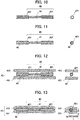
- the rubber prior to interposing the RFID tag 40 by the two rubber sheets 431, 432 constituting the protective member 43, the rubber is arranged within the spring antenna 421. More preferably, rubber is filled into the spring antenna, so that air will not remain as much as possible. This process and the reason for adopting this process will be explained using FIGS. 7 to 13 .
- FIG. 7 is a view showing a cross section of the spring antenna 421, and rubber sheets 431, 432, prior to interposing the RFID tag 40 by the rubber sheets 431, 432.
- FIG. 8 is a view showing a cross section of the spring antenna 421, and rubber sheets 431, 432, after interposing the RFID tag 40 by the rubber sheets 431, 432.
- the distance L between the outer circumferential part of the spring antenna 421 and the outer surface of the rubber sheets 431, 432 becomes very short, as shown in FIG. 9 .
- the rubber prior to interposing the RFID tag 40 by the rubber sheets 431, 432, the rubber is arranged within the spring antenna 421, as shown in FIGS. 10 to 13 . More preferably, rubber is filled within the spring antenna so that air does not remain as much as possible. It should be noted that the views shown on the right sides of FIGS. 10 to 13 are views showing a transverse section of the spring antenna 421 and the surrounding thereof.
- FIG. 10 is a view showing a state prior to filling the rubber 46 into the spring antenna 421
- FIG. 11 is a view showing a state after filling the rubber 46 into the spring antenna 421.
- the rubber 46 is embedded so as to be almost the same outside diameter as the outer circumferential face of the spring antenna 421. Then, in the case of the rubber 46 escaping from the outer circumferential face of the spring antenna 421, it is preferable to wipe off this portion.
- the outer circumferential face of the rubber 46 is preferably molded so as to become substantially the same surface as the outer circumferential face of the spring antenna 421. It should be noted that the rubber 46 may be filled into the spring antenna 421, and the outer circumference of the spring antenna 421 may be thinly wrapped by the rubber 46.
- the dimension in the width direction formed by the rubber sheets 431, 432 after interposing the RFID tag 40 becomes larger, which is not preferable.
- the rubber 46 may be embedded so as to become substantially the same outside diameter as the inner circumferential face of the spring antenna 421. It is desirable for the outer circumferential part of the rubber 46 to be located within the range of the inner circumferential face and outer circumferential face of the spring antenna 421.
- rubber having flexibility is used as the rubber 46 in order to ensure the flexibility of the spring antenna 421.
- rubber of a modulus higher than the rubber sheets 431, 432 is used as the rubber 46, in consideration of the workability, etc.
- unvulcanized rubber is used as the rubber 46 arranged within the spring antenna 421.
- rubber of lower modulus than the rubber sheets 431, 432 may be used as the rubber 46.
- rubber of substantially the same modulus, and rubber of the same material may be used.
- vulcanized rubber may be used as the rubber 46 arranged within the spring antenna 421.
- rubber-based adhesive, rubber-based filler, etc. can also be used. Taking account of configuring so as not to leave air within the spring antenna 421 as much as possible, while ensuring flexibility, it is possible to adopt various rubber-based materials.
- various methods can be adopted; however, for example, it is also possible to inject rubber into the spring antenna 421 using a syringe. In this case, a set appropriate amount of the rubber 46 may be filled using a syringe.
- portions protruding from the outer circumference of the spring antenna 421 may be wiped off.
- FIG. 12 is a view showing a state prior to interposing the RFID tag 40 into which the rubber 46 is filled in the spring antenna 421, by the rubber sheets 431, 432
- FIG. 13 is a view showing a state after interposing by the rubber sheets 431, 432.
- the rubber 46 is filled in advance into the spring antenna 421, no air pockets exist between the rubber sheets 431, 432. Consequently, since it is unnecessary to be concerned over air pockets, the process of interposing the RFID tag 40 by the rubber sheets 431, 432 also becomes easy.
- the rubber 46 being arranged within the spring antenna 421, the integrity of the spring antenna 421, rubber 46, and rubber sheets 431, 432 rises, and when the tire deforms, the spring antenna 421 follows the movement of the rubber. Consequently, the durability of the RFID tag 40 having the spring antenna 421 also improves.
- the distance L between the outer circumferential part of the spring antenna 421 and the outer circumferential face of the rubber sheets 431, 432 stabilizes. In other words, a distance close to the thickness of the rubber sheets 431, 432 is generally secured as this distance L. Consequently, the RFID tag 40 is sufficiently protected by the rubber sheets 431, 432.
- the RFID tag 40 interposed by the rubber sheets 431, 432 is fixedly set up at the bead filler 22, etc., and subsequently, the green tire is vulcanized.
- the present embodiment provides a step of arranging the rubber 46 within the spring antenna 421 of the RFID tag 40 serving as an electronic component having a communication function; a step of interposing the RFID tag 40 having the spring antenna 421 into which the rubber 46 was arranged, by the rubber sheets 431, 432, and an arrangement step of arranging the RFID tag 40 interposed by the rubber sheets 431, 432 in the tire 1.
- the air 45 will thereby not remain inside the spring antenna 421.
- the work of interposing the RFID tag 40 by the rubber sheets 431, 432 also becomes easy.
- the distance L between the outer circumferential part of the spring antenna 421 and the outer surface of the rubber sheets 431, 432 is stabilized, the RFID tag 40 is sufficiently protected by the rubber sheets 431, 432.
- the tire of the present invention can be adopted as various types of tires such as for cars, light trucks, trucks and buses, it is particularly suitable as a tire of a truck, bus, etc. It should be noted that the present invention is not to be limited to the above-mentioned embodiments, it is solely defined by the appended claims.
Description
- The present invention relates to a tire in which an electronic component is embedded.
- Conventionally, tires in which an electric component such as RFID is embedded within the rubber structure have been known. With such tires, by an RFID tag embedded in the tire and a reader as an external device carrying out communication, it is possible to perform production control of tires, usage history management, etc. For example,
Patent Document 1 shows a tire in which an electronic component is arranged at the boundary surface of two difference substances. The boundary surface of two substances at which this electronic component is arranged is a surface extending from a free edge of a carcass ply. - Patent Document 1: Japanese Unexamined Patent Application, Publication No.
2008-265750 - With the technology shown in
Patent Document 1, the boundary surface between two substances at which the electronic component is arranged becomes a surface extending from a free edge of the carcass ply; however, at this portion, stress and distortion tends to occur upon the tire deforming. Therefore, the electronic portion arranged at this portion is affected by the stress and distortion upon the tire deforming, and there is a possibility of no longer maintaining the function as an electronic component. - The documents
JP 2016 049920 A EP 3 196 056 A1US 2011/175778 A1 provide further examples of rfid tags for tire identification embedded in the bead region. - The present invention has been made taking account of the above-mentioned problem, and an object thereof is to provide a tire which can maintain the function of an embedded electronic component, by arranging the electronic component at a position which is hardly affected by the stress and distortion within the tire structure.
- A tire (for example, the tire 1) according to a first aspect of the present invention includes: a bead core (for example, the bead core 21); a bead filler (for example, the bead filler 22) which extends to an outer side in a tire radial direction of the bead core; a carcass ply (for example, the carcass ply 23) which extends from the bead core to another bead core and is folded around the bead core; a pad member (for example, the pad member 34) which is disposed at an outer side in a tire-width direction of the bead filler; and a first rubber sheet (for example, the first rubber sheet 37) disposed between the bead filler and the pad member in a state covering a folding end (for example, the folding
end 25A) of the carcass ply which is folded back, in which a second rubber sheet (for example, therubber sheet 431, 432) covering an electronic component (for example, the RFID tag 40) is disposed between the bead filler and the pad member, on an outer side in the tire-radial direction of the first rubber sheet. - According to a second aspect of the present invention, in the tire as described in the first aspect, the second rubber sheet covering the electronic component may be disposed in a region from a tire-radial direction outside end (for example, the tire-radial direction outside
end 37A) of the first rubber sheet to a tire-radial direction outside end (for example, the tire-radial direction outsideend 22A) of the bead filler. - According to a third aspect of the present invention, in the tire as described in the first or second aspect, thickness of the first rubber sheet and thickness formed by the second rubber sheet covering the electronic component may be substantially equal thicknesses at an opposing end part.
- According to a fourth aspect of the present invention, in the tire as described in any one of the first to third aspects, the first rubber sheet and the second rubber sheet may be formed in a ring shape.
- According to a fifth aspect of the present invention, the tire as described in any one of the first to fourth aspects may further include: a reinforcement ply (for example, the steel chafer 31) arranged so as to cover the carcass ply around the bead core, in which the pad member may be configured by a first pad (for example, the first pad 35) covering an outer side in the tire-width direction of the folding end of the carcass ply which is folded back, at an outer side in the tire-radial direction of an end part (for example, the
end part 31A) of the reinforcement ply; and a second pad (for example, the second pad 36) covering an outer side in the tire-width direction of the first pad. - According to a sixth aspect of the present invention, in the tire as described in any one of the first to fifth aspects, the first rubber sheet may be disposed in a state covering a folding end of the carcass ply which is folded back, from an inner side in the tire-width direction.
- According to a seventh aspect of the present invention, a tire manufacturing method for manufacturing the tire as described in the sixth aspect, includes the steps of: pasting the first rubber sheet to the bead filler; and pasting the second rubber sheet covering the electronic component to the bead filler to which the first rubber sheet is pasted, with a reference of a pasting position of the first rubber sheet.
- According to the present invention, it is possible to provide a tire which can maintain the function of an embedded electronic component, by arranging the electronic component at a position which is hardly affected by the stress and distortion within the tire structure.
-
-
FIG. 1 is a view showing a half section in a tire-width direction of a tire according to a first embodiment of the present invention; -
FIG. 2 is a partially enlarged cross-sectional view of a tire according to the first embodiment of the present invention;FIG. 3 is a view showing results of an in-plane distribution simulation of strain energy in a case of applying load to the tire of the first embodiment of the present invention; -
FIG. 4A is a view showing an RFID tag which is protected by a protective member in a tire according to the first embodiment of the present invention; -
FIG. 4B is a view showing along the cross section b-b inFIG. 4A ; -
FIG. 4C is a view showing along the cross section c-c inFIG. 4A ; -
FIG. 5 is a view showing a state pasting to bead filler a first rubber sheet and the RFID tag protected by the protective member, in the tire according to the first embodiment of the present invention; -
FIG.6 is a view showing a modified example of a protective member; -
FIG. 7 is a view showing a cross section prior to interposing the RFID tag by rubber sheets in a case of not filling rubber into a spring antenna; -
FIG. 8 is a view showing a cross section after interposing the RFID tag by rubber sheets in a case of not filling rubber inside a spring antenna; -
FIG. 9 is a view showing a cross section after interposing the RFID tag by rubber sheets in a case of not filling rubber into a spring antenna; -
FIG. 10 is a view showing the RFID tag prior to filling rubber inside a spring antenna in a tire according to a second embodiment of the present invention; -
FIG. 11 is a view showing the RFID tag after filling rubber inside a spring antenna in a tire according to the second embodiment of the present invention; -
FIG. 12 is a view showing the RFID tag prior to interposing by rubber sheets, in a tire according to the second embodiment of the present invention; and -
FIG. 13 is a view showing the RFID tag interposed by a rubber sheet, in a tire according to the second embodiment of the present invention. - Hereinafter, a first embodiment of the present invention will be explained while referencing the drawings.
FIG. 1 is a view showing a half section in a tire-width direction of atire 1 according to the present embodiment. The basic structure of the tire is left/right symmetric in the cross section of the tire-width direction; therefore, a cross-sectional view of the right half is shown herein. In the drawings, the reference symbol S1 is the tire equatorial plane. The tire equatorial plane S1 is a plane orthogonal to the tire rotation axis, and is positioned in the center of the tire-width direction. Herein, tire-width direction is a direction parallel to the tire rotation axis, and is the left/right direction of the paper plane of the cross-sectional view inFIG. 1 . InFIG. 1 , it is illustrated as the tire-width direction X. Then, inner-side of tire-width direction is a direction approaching the tire equatorial plane Sl, and is the left side of the paper plane inFIG. 1 . Outer side of tire-width direction is a direction distancing from the tire equatorial plane S1, and is the right side of the paper plane inFIG. 1 . In addition, tire-radial direction is a direction perpendicular to the tire rotation axis, and is the vertical direction in the paper plane ofFIG. 1 . InFIG. 1 , it is illustrated as the tire-radial direction Y. Then, outer-side of tire-radial direction is a direction distancing from the tire rotation axis, and is the upper side of the paper plane inFIG. 1 . Inner-side of tire-radial direction is a direction approaching the tire rotation axis, and is the lower side of the paper plane inFIG. 1 . The same also applies toFIGS. 2 and5 . - The
tire 1 is a tire for trucks and buses, for example, and includes a pair ofbeads 11 provided at both sides in the tire width direction,tread 12 forming a contact patch with the road surface, and a pair ofsidewalls 13 which extends between the pair of beads and thetread 12. - The
bead 11 includes anannular bead core 21 formed by wrapping around several times bead wires made of metal coated with rubber, and abead filler 22 of tapered shape extending to the outer side in the tire-radial direction of thebead core 21. Thebead filler 22 is configured by afirst bead filler 221 which covers the outer circumference of thebead core 21, and asecond bead filler 222 which is arranged on the outer side in the tire-radial direction of thefirst bead filler 221. Thesecond bead filler 222 is configured from rubber with a modulus higher than aninner liner 29 andside wall rubber 30 described later. Then, thefirst bead filler 221 is configured from rubber of an even higher modulus than thesecond bead filler 222. It should be noted that thefirst bead filler 221 may be a form not covering the outer circumference of thebead core 21, if at least a part thereof is arranged on the outer side in the tire-radial direction of thebead core 21. In addition, thebead filler 22 may be formed from rubber of one type. In other words, it may not necessarily be divided into thefirst bead filler 221 andsecond bead filler 222. Thebead core 21 is a member which plays a role of fixing a tire filled with air to the rim of a wheel which is not illustrated. Thebead filler 22 is a member provided in order to raise the rigidity of the bead peripheral part and to ensure high maneuverability and stability. - A carcass ply 23 constituting a ply serving as the skeleton of the tire is embedded inside of the
tire 1. The carcass ply 23 extends from one bead core to the other bead core. In other words, it is embedded in thetire 1 between the pair ofbead cores 21, in a form passing through the pair ofside walls 13 and thetread 12. As shown inFIG. 1 , the carcass ply 23 includes aply body 24 which extends from one bead core to the other bead core, and extends between thetread 12 andbead 11, and aply folding part 25 which is folded around thebead core 21. Herein, afolding end 25A of theply folding part 25 is positioned more to an inner side in the tire-radial direction than a tire-radial direction outsideend 22A of thebead filler 22. The carcass ply 23 is configured by a plurality of ply cords extending in a tire-width direction. In addition, a plurality of ply cords is arranged side by side in a tire circumferential direction. This ply cord is configured by a metal steel cord, or an insulated organic fiber cord such as polyester or polyamide, or the like, and is covered by rubber. - In the
tread 12, a plurality of layers ofsteel belts 26 is provided in the outer side in the tire radial direction of thecarcass ply 23. Thesteel belt 26 is configured by a plurality of steel cords covered by rubber. By providing thesteel belts 26, the rigidity of the tire is ensured, and the contact state of the road surface with thetread 12 improves. In the present embodiment, although four layers ofsteel belts 26 are provided, the number of layeredsteel belt 26 is not limited thereto. - The
tread rubber 28 is provided at the outer side in the tire-radial direction of thesteel belt 26. A tread pattern (not illustrated) is provided to the outer surface of thetread rubber 28, and this outer surface serves as a contact surface which contacts with the road surface. - In the vicinity of the outer side in the tire-width direction of the
tread 12, in a region between thecarcass ply 23, and thesteel belts 26 /tread rubber 28, ashoulder pad 38 is provided. Thisshoulder pad 38 extends until a region of the outer side in the tire-radial direction of theside wall 13, and part thereof forms an interface betweenside wall rubber 30 described later. In other words, in the region of the outer side in the tire-radial direction of theside wall 13, a part of theshoulder pad 38 is present on the inner side in the tire width direction of theside wall rubber 30. Theshoulder pad 38 consists of a rubber member having cushioning, and exhibits a cushion function between thecarcass ply 23 andsteel belt 26. In addition, since theshoulder pad 38 consists of rubber having a characteristic of low heat buildup, it is possible to suppress heat generation effectively, by extending until theside wall 13. - In the
side wall 13, theside wall rubber 30 constituting the outer wall surface of thetire 1 is provided to the outer side in the tire-width direction of thecarcass ply 23. Thisside wall rubber 30 is a portion which bends the most upon the tire exhibiting a cushioning action, and usually flexible rubber having fatigue resistance is adopted therein. - In the
side wall 13, theside wall rubber 30 constituting the outer wall surface of thetire 1 is provided to the outer side in the tire-width direction of thecarcass ply 23. Thisside wall rubber 30 is a portion which bends the most upon the tire exhibiting a cushioning action, and usually flexible rubber having fatigue resistance is adopted therein. - On the inner side in the tire radial direction of the carcass ply 23 provided around the
bead core 21 of thebead 11, asteel chafer 31 serving as a reinforcement ply is provided so as to cover at least part of thecarcass ply 23. Thesteel chafer 31 also extends to the outer side in the tire-width direction of theply folding part 25 of thecarcass ply 23, and anend part 31A of thissteel chafer 31 is positioned more to the inner side in the tire-width direction than thefolding end 25A of theply folding part 25. Thissteel chafer 31 is a metal reinforcement layer configured by metal steel cords, and is covered by rubber. -
Rim strip rubber 32 is provided at the inner side in the tire-radial direction of thesteel chafer 31. Thisrim strip rubber 32 is arranged along the outer surface of the tire, and connects with theside wall rubber 30. Thisrim strip rubber 32 andside wall rubber 30 are rubber members constituting the outer surface of the tire. - Then, at the outer side in the tire-radial direction of the
end part 31A of thesteel chafer 31, which is at the outer side in the tire-width direction of thefolding part 25 of thecarcass ply 23 andbead filler 22, afirst pad 35 is provided. Thisfirst pad 35 is provided so as to cover the outer side in the tire-width direction of at least thefolding end 25A of theply folding part 25. The outer side in the tire-radial direction of thefirst pad 35 is formed so as to taper as approaching the outer side in the tire-radial direction. - Furthermore, a
second pad 36 is provided so as to cover the outer side in the tire-width direction of thefirst pad 35. In more detail, thesecond pad 36 is provided so as to cover the outer side in the tire-width direction of part of thesteel chafer 31, thefirst pad 35, part of thesecond bead filler 222, and part of theply body 24 of thecarcass ply 23. Then, the side-wall rubber 30 is arranged at the outer side in the tire-width direction in a region of the outer side in the tire-radial direction of thesecond pad 36, and therim strip rubber 32 is arranged at an outer side in the tire-width direction in a region on the inner side in the tire-radial direction of thesecond pad 36. In other words, thesecond pad 36 is provided between thefirst pad 35, etc., and therim strip rubber 32 andside wall rubber 30, which are members constituting the outer surface of the tire. - Herein, the
first pad 35 andsecond pad 36 are configured by rubber of higher modulus than the modulus of the bead filler (second bead filler 222) to which these members contact. In more detail, thesecond pad 36 is configured by rubber of higher modulus than thesecond bead filler 222, and thefirst pad 35 is configured by rubber of even higher modulus than thesecond pad 36. Thefirst pad 35 andsecond pad 36 have a function of mitigating sudden distortion caused by the local rigidity point of change at thefolding end 25A of thecarcass ply 23 and theend part 31A of thesteel chafer 31. - At the inner side in the tire-width direction of the
first pad 35, afirst rubber sheet 37 is arranged in the vicinity of thefolding end 25A of theply folding part 25. Thefirst rubber sheet 37 is arranged so as to cover at least thefolding end 25A of theply folding part 25 from the inner side in the tire-width direction. - Generally, at the
folding end 25A of theply folding part 25, stress tends to concentrate. However, by providing the aforementionedfirst pad 35 andsecond pad 36, and further arranging thefirst rubber sheet 37, it becomes possible to effective suppress the concentration of stress. It should be noted that it is preferable for thepad member 34 to be configured by the aforementionedfirst pad 35 andsecond pad 36 to mitigate the influence of distortion. It should be noted that thefirst rubber sheet 37 preferably adopts a form arranging so as to cover thefolding end 25A of theply folding part 25 from the inner side in the tire-width direction, as shown inFIG. 1 ; however, it will possess a similar effect even if adopting a configuration covering thefolding end 25A of theply folding part 25 from the outer side in the tire-width direction. - An
RFID tag 40 is embedded as an electrical component in thetire 1 of the present embodiment. TheRFID tag 40 is a passive transponder equipped with an RFID chip and an antenna for performing communication with external equipment, and performs wireless communication with a reader (not illustrated) serving as the external equipment. As the antenna, a coil-shaped spring antenna, plate-shaped antenna, and various types of rod-shaped antennas can be used. For example, it may be an antenna formed by printing a predetermined pattern on a flexible substrate. The antenna is established at an antenna length optimized according to the frequency band, etc. to be used. In a storage part inside the RFID chip, identification information such as a manufacturing number and part number is stored. -
FIG. 2 is an enlarged cross-sectional view showing the periphery of an embedded part of theRFID tag 40 in thetire 1 ofFIG. 1 . As shown inFIGS. 1 and2 , theRFID tag 40 is arranged between thebead filler 22 and thepad member 34 arranged on the outer side in the tire-width direction of thebead filler 22, at the outer side in the tire-radial direction of thefirst rubber sheet 37. In the present embodiment, thepad member 34 arranged on the outer side in the tire-width direction of thebead filler 22 is configured by afirst pad 35 and asecond pad 36. Herein, theRFID tag 40 is covered by a rubber sheet serving as a protective member described later. TheRFID tag 40 covered by the rubber sheet, as shown inFIGS. 1 and2 , is arranged in a region between the tire-radial direction outsideend 37A of thefirst rubber sheet 37 and the tire-radial direction outsideend 22A of thebead filler 22. - It should be noted that, if establishing the modulus of the
second pad 36 as a reference, the side-wall rubber 30 is preferably established with a modulus of 0.4 to 0.6 times that of thesecond pad 36. In addition, thefirst pad 35 is preferably established with a modulus of 1.1 to 1.2 times that of thesecond pad 36. In addition, thesecond bead filler 22 is preferably established with a modulus of 0.7 to 0.8 times that of the second pad. By establishing such a modulus, it is possible to keep a balance of flexibility as a tire and rigidity in the vicinity of thebead 11. It should be noted that the modulus indicates 100% elongation modulus (M100) under a 23°C atmosphere, measured in accordance with "3.7 stress at a given elongation, S" of JIS K6251:2010. - As mentioned above, normally, in a case of the boundary surface of two substances being a surface extending from the
folding end 25A of thecarcass ply 23, distortion tends to occur at this surface. However, in the present embodiment, thefirst rubber sheet 37 is arranged in a form covering thefolding end 25A of thecarcass ply 23, between thebead filler 22 and thepad member 34 arranged at the outer side in the tire-width direction of thebead filler 22; therefore, the outer side in the tire-radial direction of thefirst rubber sheet 37 becomes a portion which is hardly influenced by distortion. -
FIG. 3 is a view showing the results of in-plane distribution simulation of strain energy, in a case of assembling thetire 1 of the present invention to a rim, and applying 100% load. The enlarged cross-sectional view shown inFIG. 3 displays by dividing the region in five, according to the magnitude of the strain energy. Herein, a region having the highest strain energy is defined aslevel 5, a region having high strain energy is defined aslevel 4, a region in which the strain energy somewhat declined is defined aslevel 3, a region in which the strain energy further declined is defined aslevel 2, and the region in which the strain energy declined the most is defined aslevel 1.FIG. 3 displays by dividing the regions with bold dotted lines as the boundary. - On the outer side in the tire-radial direction of the
first rubber sheet 37, the boundary surface between thebead filler 22 and thepad member 34 arranged on the outer side in the tire-width direction of thebead filler 22 becomes a region of mostlylevel 2, and thus there is little strain energy. Consequently, upon arranging theRFID tag 40, it is a preferable region. In addition, this position is a position separated a certain extent from the outer surface of thetire 1; therefore, the influence relative to external wounds is also hardly received. Furthermore, since the outer side in the tire-width direction is protected by thesecond pad 36 having a high modulus of elasticity, it hardly receives influence relative to external wounds. - Herein, the
RFID tag 40 is covered by therubber sheets second rubber sheet 43. In other words, in the present embodiment, thesecond rubber sheet 43 is constituted by the tworubber sheets FIGS. 4A to 4C. FIG. 4A is a view showing theRFID tag 40 covered by theprotective member 43 serving as the second rubber sheet. InFIG. 4A , theRFID tag 40 is covered and hidden by therubber sheet 431 described later.FIG. 4B is a cross-sectional view along the line b-b inFIG. 4A, and FIG. 4C is a cross-sectional view along the line c-c inFIG. 4A . In the present embodiment, as shown inFIGS. 4A to 4C , theRFID tag 40 is covered by theprotective member 43. - The
RFID tag 40 includes anRFID chip 41 andantenna 42 for performing communication with external equipment. As theantenna 42, a coil-shaped spring antenna, plate-shaped antenna, and various types of rod-shaped antennas can be used. When considering the communicability and flexibility, a coil-shaped spring antenna is the most preferable. - The
protective member 43 is configured from tworubber sheets RFID tag 40. - The
protective member 43 is configured by rubber of a predetermined modulus, for example. - As the rubber adopted in the
protective member 43, rubber at least having a higher modulus than theside wall rubber 30 is used. For example, rubber having a higher modulus than thesecond bead filler 222 and lower modulus than thepad member 34 is used. - For example, with the modulus of the
side wall rubber 30 as a reference, it is preferable to use rubber of a modulus 1.1 to 1.8 times as the rubber used in theprotective member 43. At this time, as the rubber of thesecond pad 36, rubber of a modulus 1.6 to 3 times that of the side wall rubber, for example, rubber of a modulus on the order of 2 times thereof, may be used. It should be noted that, if emphasizing reinforcement of the protection of theRFID tag 40, rubber of a modulus higher than thesecond pad 36 may be adopted as the rubber used in theprotective member 43. - It should be noted that, as shown in
FIGS. 1 and2 , theRFID tag 40 is arranged in the region between thebead filler 22 andpad member 34. Therefore, by setting the modulus of theprotective member 43 to a value with a higher modulus than thebead filler 22 and a lower modulus than thepad member 34, in the case of the tire distorting, it is possible to prevent excessive stress from generating within the rubber structure at the embedded part of theRFID tag 40. In other words, it is possible to suppress the generation of stress. - In addition, the
protective member 43 may be configured from a short-fiber filler mixed rubber. As the short-fiber filler, for example, it is possible to use insulating short fibers like organic short fibers such as aramid short fibers and cellulose short fibers; inorganic short fibers such as ceramic short fibers as in alumina short fiber, and glass short fiber. By mixing such short-fiber fillers into rubber, it is possible to raise the strength of the rubber. In addition, as theprotective member 43, a rubber sheet in the vulcanized state may be used. The rubber sheet in a vulcanized state does not plastically deform as would raw rubber, and thus can appropriately protect theRFID tag 40. - In addition, as the
protective member 43, an organic fiber layer from polyester fibers or polyamide fibers may be provided. It is also possible to embed an organic fiber layer in the tworubber sheets - Herein, the thickness of the
first rubber sheet 37 and the thickness after coating formed by the tworubber sheets RFID tag 40 are preferably substantially the same thicknesses, as shown inFIGS. 1 and2 at opposing end parts. By making as substantially the same thickness, there will not be a step in this portion. It is thereby possible to suppress mixing of air, and thus the quality of the tire when completed improves. -
FIG. 5 is a drawing when viewing thebead filler 2 during the manufacturing process from an outer side in the tire-width direction, and shows a state pasting thefirst rubber sheet 37 and theRFID tag 40 protected by theprotective member 43 to thebead filler 22. As shown inFIG. 5 , thebead filler 22 andfirst rubber sheet 37 constituting thebead 11 are each ring shapes. In other words, thebead filler 22 andfirst rubber sheet 37 constituting thebead 11 are each hollow disk shapes. - The
RFID tag 40 is mounted in the manufacturing process of the tire prior to the vulcanization process. In the present embodiment, as shown inFIG. 5 , thefirst rubber sheet 37 is pasted to thebead filler 22 prior to being vulcanized, and subsequently, therubber sheet RFID tag 40 is pasted with the reference of the pasting position of thefirst rubber sheet 37. At this time, thebead filler 22,first rubber sheet 37 and therubber sheet RFID tag 40, due to being in the state of raw rubber prior to vulcanization, can be pasted using the adhesive property thereof. Alternatively, in a case of the adhesive property being low or the like, it may be pasted using an adhesive, etc. After pasting therubber sheet rubber sheets bead filler 22 andpad member 34. Subsequently, the green tire in which each constituent member including theRFID tag 40 is assembled is vulcanized in the vulcanization process to manufacture the tire. - It should be noted that the
first rubber sheet 37 is formed in a ring shape so as to establish a situation covering thefolding end 25A of the carcass ply 23 over the entire circumference after green tire assembly. - It should be noted that, the
first rubber sheet 37 is pasted to thepad member 34, and subsequently, therubber sheet RFID tag 40 may be pasted with the pasting position of the first rubber sheet as a reference, and then establishing a situation interposed by thebead filler 22. - In this way, in the present embodiment, since it is possible to paste the
RFID tag 40 using rubber in its raw rubber state, at the time of tire manufacture, the assembly work of theRFID tag 40 in the manufacturing process of the tire is easy. In particular, thebead filler 22 has a certain rigidity even in the raw rubber state, and thus the assembly work of theRFID tag 40 is easy. - In addition, if configuring the
protective member 43 by way of two rubber sheets, since it is possible to thinly form theRFID tag 40 including theprotective member 43, it is favorable upon embedding in thetire 1. In addition, when assembling theRFID tag 40 in the constituent members of thetire 1 prior to vulcanizing, theRFID tag 40 covered by the rubber sheet can be very easily installed. For example, at the desired position of members such as thebead filler 22 prior to vulcanization, it is possible to appropriately paste theRFID tag 40 covered by the rubber sheet using the stickiness of raw rubber. In addition, by also establishing therubber sheets - However, the
protective member 43 can be employed in various forms, not limited to the form configured by two rubber sheets. For example, so long as the rubber sheet constituting the protective member covers at least part of theRFID tag 40, effects such as an improvement in workability during the manufacturing process and stress mitigation are obtained. In addition, for example, it may be a configuration wrapping one rubber sheet over the entire circumference of theRFID tag 40, or a configuration adhering a protective member in the form of a potting agent having high viscosity over the entire circumference of theRFID tag 40. Even if such a configuration, it is possible to appropriately protect theRFID tag 40. - It should be noted that the
RFID tag 40 covered by theprotective member 43 is embedded in the tire so that the longitudinal direction thereof is the direction of a tangent line relative to the circumferential direction of the tire, i.e. direction orthogonal to the paper plane in the cross-sectional views ofFIGS. 1 and2 . In addition, therubber sheets rubber sheets bead filler 22. By establishing such a form, stress hardly acts on theRFID tag 40 also when the tire deformed. In addition, the work for attaching theRFID tag 40 covered by theprotective member 43 in the manufacturing process becomes simple. - Herein, in the attaching process of the
RFID tag 40, by establishing the outer circumference of the ring-shapedfirst rubber sheet 37 as a reference, it is possible to easily arrange theRFID tag 40 covered by theprotective member 43 in the aforementioned direction. In other words, as shown inFIG. 5 , therubber sheets RFID tag 40 are pasted along the outer circumference of the ring-shapedfirst rubber sheet 37. At this time, as shown inFIG. 5 , therubber sheets first rubber sheet 37. Using a flexible coil-shaped spring antenna or the like as the antenna of theRFID tag 40, a form such that the antenna also deforms following the deformation of therubber sheets first rubber sheet 37, the longitudinal direction of therubber sheets RFID tag 40 may be pasted so as to substantially match the tangential direction of the outer circumference of the ring-shapedfirst rubber sheet 37. By way of this method, it is possible to arrange theRFID tag 40 covered by theprotective member 43 simply and accurately in the aforementioned direction, without giving special markers. In addition, the thickness of the bead when tire is completed is also stable, and the variation in manufacture also decreases. - Furthermore, as shown in
FIG. 6 , thefirst rubber sheet 37 and therubber sheets - It should be noted that, in the present embodiment, although the
RFID tag 40 is embedded in the tire as an electronic component, the electronic component embedded in the tire is not limited to an RFID tag. For example, it may be various electronic components such as a sensor which carries out wireless communication. In addition, since the electronic component handles electrical information such as sending and receiving of electrical signals, there is a possibility of the performance declining due to metal components being present in the vicinity thereof. In addition, there is a possibility of the electronic component being damaged by excessive stress being applied. Consequently, even in the case of embedding various electronic components in a tire, it is possible to obtain the effects of the present invention. For example, the electronic component may be a piezoelectric element or strain sensor. - According to the
tire 1 of the present embodiment, the following effects are exerted. - (1) The
tire 1 according to the present embodiment includes thefirst rubber sheet 37 arranged between thebead filler 22 andpad member 34 in a form covering thefolding end 25A of the carcass ply which was folded back, and therubber sheets RFID tag 40 are arranged between thebead filler 22 andpad member 34 on the outer side in the tire-radial direction of thefirst rubber sheet 37. TheRFID tag 40 can thereby keep the function thereof, without being influenced by excessive distortion. - (2) In the
tire 1 according to the present embodiment, therubber sheets RFID tag 40 are arranged in a region between the tire-radial direction outsideend 37A of thefirst rubber sheet 37 and the tire-radial direction outsideend 22A of thebead filler 22. TheRFID tag 40 is thereby even less influenced by distortion. - (3) In the
tire 1 according to the present embodiment, the thickness of thefirst rubber sheet 37 and the thicknesses of therubber sheets RFID tag 40 are substantially the same thicknesses at an opposing end part. It is thereby possible to suppress mixing of air during assembly, and thus the quality when the tire is completed improves. - (4) In the
tire 1 according to the present embodiment, thefirst rubber sheet 37 and therubber sheets - (5) The
tire 1 according to the present embodiment further includes thesteel chafer 31 arranged so as to cover the carcass ply 23 around thebead filler 21, and thepad member 34 is configured, at the outer side of the tire-radial direction of theend part 31A of thesteel chafer 31, from thefirst pad 35 covering the outer side in the tire-width direction of thefolding end 25A of the carcass ply 23 which is folded back, and thesecond pad 36 covering the outer side in the tire-width direction of thefirst pad 35. The amount of distortion generated at the boundary surface between thebead filler 22 andpad member 34 is thereby suppressed. - (6) In the
tire 1 according to the present embodiment, thefirst rubber sheet 37 is arranged in a form covering thefolding end 25A of the carcass ply 23 which is folded back, from the inner side in the tire-width direction. The amount of distortion generated at the boundary surface between thebead filler 22 andpad member 34 is thereby suppressed. - (7) The manufacturing method of the
tire 1 according to the present embodiment includes: a step of pasting thefirst rubber sheet 37 to thebead filler 22, and pasting therubber sheets RFID tag 40 on thebead filler 22 to which thefirst rubber sheet 37 is pasted, with the reference of the pasting position of thefirst rubber sheet 37. It is thereby possible to arrange theRFID tag 40 covered by theprotective member 43 simply and accurately in the aforementioned direction, without giving special markers. In addition, the thickness of the bead when the tire is completed is also stable, and the variation in manufacture also decreases. - Next, a tire according to a second embodiment will be explained while referencing
FIGS. 7 to 13 . It should be noted that, in the following explanation, the same reference symbol will be attached for configurations which are the same as the first embodiment, and detailed explanations thereof will be omitted. The present embodiment is a particularly preferable embodiment in the case of the antenna of theRFID tag 40 being a coil-shaped spring antenna. - In the
RFID tag 40 of the present embodiment, a coil-shapedspring antenna 421 having high communicability and flexibility can be used as the antenna. Thespring antenna 421 is set to an antenna length which was optimized according to the frequency band, etc. to be used. - In the present embodiment, prior to interposing the
RFID tag 40 by the tworubber sheets protective member 43, the rubber is arranged within thespring antenna 421. More preferably, rubber is filled into the spring antenna, so that air will not remain as much as possible. This process and the reason for adopting this process will be explained usingFIGS. 7 to 13 . - First, a state of the surroundings of the
RFID tag 40 in a case of not filling rubber into thespring antenna 421 will be explained as a reference example usingFIGS. 7 to 9. FIG. 7 is a view showing a cross section of thespring antenna 421, andrubber sheets RFID tag 40 by therubber sheets FIG. 8 is a view showing a cross section of thespring antenna 421, andrubber sheets RFID tag 40 by therubber sheets - As shown in
FIG. 8 , in this reference example, since rubber is not filled into thespring antenna 421 in advance, a certain amount ofair 45 may remain within thespring antenna 421 after interposing by therubber sheets rubber sheets spring antenna 421 becomes insufficient, and when the tire deforms, there is concern over thespring antenna 421 not following the motion of the rubber, and theRFID tag 40 having thespring antenna 421 being damaged. - It should be noted that raw rubber before vulcanization is used as the
rubber sheets rubber sheets rubber sheets FIG. 8 . However, very large amounts of time and labor are required in order to stick therubber sheets - Then, even if assuming a case of taking time and sticking the rubber sheets until the inside of the spring antenna is embedded, the distance L between the outer circumferential part of the
spring antenna 421 and the outer surface of therubber sheets FIG. 9 . In addition, it is difficult to stabilize this distance L, and locally thin portions can occur. Consequently, the protection of theRFID tag 40 by therubber sheets rubber sheets - Therefore, in the present embodiment, prior to interposing the
RFID tag 40 by therubber sheets spring antenna 421, as shown inFIGS. 10 to 13 . More preferably, rubber is filled within the spring antenna so that air does not remain as much as possible. It should be noted that the views shown on the right sides ofFIGS. 10 to 13 are views showing a transverse section of thespring antenna 421 and the surrounding thereof. -
FIG. 10 is a view showing a state prior to filling therubber 46 into thespring antenna 421, andFIG. 11 is a view showing a state after filling therubber 46 into thespring antenna 421. Therubber 46 is embedded so as to be almost the same outside diameter as the outer circumferential face of thespring antenna 421. Then, in the case of therubber 46 escaping from the outer circumferential face of thespring antenna 421, it is preferable to wipe off this portion. In other words, the outer circumferential face of therubber 46 is preferably molded so as to become substantially the same surface as the outer circumferential face of thespring antenna 421. It should be noted that therubber 46 may be filled into thespring antenna 421, and the outer circumference of thespring antenna 421 may be thinly wrapped by therubber 46. On the other hand, if thickly wrapping thespring antenna 421 by therubber 46, in addition to the flexibility of thespring antenna 421 being harmed, the dimension in the width direction formed by therubber sheets RFID tag 40 becomes larger, which is not preferable. It should be noted that therubber 46 may be embedded so as to become substantially the same outside diameter as the inner circumferential face of thespring antenna 421. It is desirable for the outer circumferential part of therubber 46 to be located within the range of the inner circumferential face and outer circumferential face of thespring antenna 421. - Herein, rubber having flexibility is used as the
rubber 46 in order to ensure the flexibility of thespring antenna 421. However, it is preferable to use rubber of a modulus higher than therubber sheets rubber 46, in consideration of the workability, etc. It should be noted that preferably unvulcanized rubber is used as therubber 46 arranged within thespring antenna 421. By establishing therubber 46 andrubber sheets rubber 46,rubber sheets spring antenna 421 rises. In addition, therubber 46, andrubber sheets spring antenna 421, rubber of lower modulus than therubber sheets rubber 46. In addition, rubber of substantially the same modulus, and rubber of the same material may be used. It should be noted that vulcanized rubber may be used as therubber 46 arranged within thespring antenna 421. In addition, rubber-based adhesive, rubber-based filler, etc. can also be used. Taking account of configuring so as not to leave air within thespring antenna 421 as much as possible, while ensuring flexibility, it is possible to adopt various rubber-based materials. As the arranging operation of therubber 46, various methods can be adopted; however, for example, it is also possible to inject rubber into thespring antenna 421 using a syringe. In this case, a set appropriate amount of therubber 46 may be filled using a syringe. In addition, after filling a large amount of therubber 46, portions protruding from the outer circumference of thespring antenna 421 may be wiped off. -
FIG. 12 is a view showing a state prior to interposing theRFID tag 40 into which therubber 46 is filled in thespring antenna 421, by therubber sheets FIG. 13 is a view showing a state after interposing by therubber sheets - As shown in
FIG. 13 , according to the present embodiment, since therubber 46 is filled in advance into thespring antenna 421, no air pockets exist between therubber sheets RFID tag 40 by therubber sheets rubber 46 being arranged within thespring antenna 421, the integrity of thespring antenna 421,rubber 46, andrubber sheets spring antenna 421 follows the movement of the rubber. Consequently, the durability of theRFID tag 40 having thespring antenna 421 also improves. - In addition, according to the present embodiment, the distance L between the outer circumferential part of the
spring antenna 421 and the outer circumferential face of therubber sheets rubber sheets RFID tag 40 is sufficiently protected by therubber sheets RFID tag 40 interposed by therubber sheets bead filler 22, etc., and subsequently, the green tire is vulcanized. - According to the tire of the present embodiment, the following effects are exerted in addition to the above (1) to (5) .
- (6) The present embodiment provides a step of arranging the
rubber 46 within thespring antenna 421 of theRFID tag 40 serving as an electronic component having a communication function; a step of interposing theRFID tag 40 having thespring antenna 421 into which therubber 46 was arranged, by therubber sheets RFID tag 40 interposed by therubber sheets tire 1. Theair 45 will thereby not remain inside thespring antenna 421. In addition, since it is unnecessary to be concerned about air pockets, the work of interposing theRFID tag 40 by therubber sheets spring antenna 421 and the outer surface of therubber sheets RFID tag 40 is sufficiently protected by therubber sheets - It should be noted that, although the tire of the present invention can be adopted as various types of tires such as for cars, light trucks, trucks and buses, it is particularly suitable as a tire of a truck, bus, etc. It should be noted that the present invention is not to be limited to the above-mentioned embodiments, it is solely defined by the appended claims.
-
- 1
- tire
- 11
- bead
- 12
- tread
- 13
- side wall
- 21
- bead core
- 22
- bead filler
- 23
- carcass ply
- 24
- ply body
- 25
- ply folding part
- 25A
- folding end
- 26
- steel belt
- 28
- tread rubber
- 29
- inner liner
- 30
- side-wall rubber
- 31
- steel chafer
- 31A
- end part of steel chafer
- 32
- rim strip rubber
- 34
- pad member
- 35
- first pad
- 36
- second pad
- 37
- first rubber sheet
- 37A
- tire-radial direction outside end
- 40
- RFID tag
- 41
- RFID chip
- 42
- antenna
- 421
- spring antenna
- 43
- second rubber sheet
- 431, 432
- rubber sheet
- 46
- rubber
Claims (7)
- A tire (1) comprising:a bead core (21); a bead filler (22) which extends to an outer side in a tire radial direction of the bead core (21); a carcass ply (23) which extends from the bead core (21) to another bead core and is folded around the bead core (21); a pad member (34) which is disposed at an outer side in a tire-width direction of the bead filler (22); characterised bya first rubber sheet (37) disposed between the bead filler (22) and the pad member (34) in a state covering a folding end (25A) of the carcass ply (23) which is folded back, anda second rubber sheet (43) covering an electronic component (40) is disposed between the bead filler (22) and the pad member (34), on an outer side in the tire-radial direction of the first rubber sheet (37).
- The tire (1) according to claim 1, wherein the second rubber sheet (43) covering the electronic component (40) is disposed in a region from a tire-radial direction outside end (37A) of the first rubber sheet (37) to a tire-radial direction outside end (22A) of the bead filler (22).
- The tire (1) according to claim 1 or 2, wherein thickness of the first rubber sheet (37) and thickness formed by the second rubber sheet (43) covering the electronic component (40) are substantially equal thicknesses at an opposing end part.
- The tire (1) according to any one of claims 1 to 3, wherein the first rubber sheet (37) and the second rubber sheet (43) are formed in a ring shape.
- The tire (1) according to any one of claims 1 to 4, further comprising a reinforcement ply (31) arranged so as to cover the carcass ply (23) around the bead core (21),
wherein the pad member (34) is configured by
a first pad (35) covering an outer side in the tire-width direction of the folding end (25A) of the carcass ply (23) which is folded back, at an outer side in the tire-radial direction of an end part (31A) of the reinforcement ply (31); and
a second pad (36) covering an outer side in the tire-width direction of the first pad (35). - The tire (1) according to any one of claims 1 to 5, wherein the first rubber sheet (37) is disposed in a state covering a folding end (25A) of the carcass ply (23) which is folded back, from an inner side in the tire-width direction.
- A tire manufacturing method for manufacturing the tire (1) according to claim 6, the method comprising the steps of:pasting the first rubber sheet (37) to the bead filler (22) ; andpasting the second rubber sheet (43) covering the electronic component (40) to the bead filler (22) to which the first rubber sheet (37) is pasted, with a reference of a pasting position of the first rubber sheet (37).
Applications Claiming Priority (1)
| Application Number | Priority Date | Filing Date | Title |
|---|---|---|---|
| JP2018188136A JP6594510B1 (en) | 2018-10-03 | 2018-10-03 | Tire and tire manufacturing method |
Publications (2)
| Publication Number | Publication Date |
|---|---|
| EP3632707A1 EP3632707A1 (en) | 2020-04-08 |
| EP3632707B1 true EP3632707B1 (en) | 2020-11-11 |
Family
ID=68084737
Family Applications (1)
| Application Number | Title | Priority Date | Filing Date |
|---|---|---|---|
| EP19200349.9A Active EP3632707B1 (en) | 2018-10-03 | 2019-09-30 | Tire and tire manufacturing method |
Country Status (4)
| Country | Link |
|---|---|
| US (1) | US11084333B2 (en) |
| EP (1) | EP3632707B1 (en) |
| JP (1) | JP6594510B1 (en) |
| CN (1) | CN110978898B (en) |
Family Cites Families (22)
| Publication number | Priority date | Publication date | Assignee | Title |
|---|---|---|---|---|
| JP3860921B2 (en) * | 1998-10-01 | 2006-12-20 | 横浜ゴム株式会社 | Auxiliary parts for tire transponders |
| US6724301B2 (en) * | 2001-11-20 | 2004-04-20 | Continental Aktiengesellschaft | Tire to wheel data transfer system |
| JP3886847B2 (en) * | 2002-05-24 | 2007-02-28 | 横浜ゴム株式会社 | Tire pressure sensor tag |
| DE102005000755A1 (en) * | 2005-01-04 | 2006-07-20 | Continental Aktiengesellschaft | Vehicle tires |
| EP2275286B1 (en) * | 2006-04-25 | 2019-10-09 | Bridgestone Americas Tire Operations, LLC | Elastomeric article with wireless micro and nano sensor system |
| JP2008195189A (en) * | 2007-02-13 | 2008-08-28 | Mitomo Shoji Kk | Tire |
| FR2914585B1 (en) | 2007-04-03 | 2009-07-03 | Michelin Soc Tech | PNEUMATIC COMPRISING AN ELECTRONIC MEMBER AND METHOD OF MANUFACTURING SUCH PNEUMATIC |
| FR2936185B1 (en) * | 2008-09-25 | 2011-09-23 | Michelin Soc Tech | PNEUMATIC HAVING A DELETED ANTENNA ORGAN |
| US8430142B2 (en) * | 2009-02-25 | 2013-04-30 | The Goodyear Tire & Rubber Company | Environmentally resistant assembly containing an electronic device for use in a tire |
| KR101059589B1 (en) * | 2009-05-06 | 2011-08-25 | 금호타이어 주식회사 | RFID tag embedded tire |
| JP5899642B2 (en) * | 2011-04-05 | 2016-04-06 | 横浜ゴム株式会社 | Pneumatic tire |
| US20120291936A1 (en) * | 2011-05-19 | 2012-11-22 | Robert Edward Lionetti | Embedded transponder and tire assembly and method of construction thereof |
| JP5319736B2 (en) * | 2011-06-15 | 2013-10-16 | 東洋ゴム工業株式会社 | Pneumatic radial tire |
| JP2013067676A (en) * | 2011-09-20 | 2013-04-18 | Sumitomo Rubber Ind Ltd | Heavy-duty pneumatic tire |
| JP5986513B2 (en) | 2013-02-07 | 2016-09-06 | 住友ゴム工業株式会社 | Heavy duty tire |
| US8977422B1 (en) * | 2013-11-06 | 2015-03-10 | The Goodyear Tire & Rubber Company | Accoustic/vibration sensor and tire assembly and method of construction thereof |
| WO2015088890A1 (en) | 2013-12-13 | 2015-06-18 | Bridgestone Americas Tire Operations, Llc | Tire having an electronic device in a lower sidewall |
| JP6754168B2 (en) * | 2014-08-08 | 2020-09-09 | 株式会社ブリヂストン | tire |
| JP6423653B2 (en) * | 2014-09-01 | 2018-11-14 | 株式会社ブリヂストン | tire |
| BR112017005528B1 (en) | 2014-10-16 | 2021-06-15 | Bridgestone Americas Tire Operations, Llc | TIRE WHICH HAS INCORPORATED AN ELECTRONIC DEVICE ATTACHED WITH ADHESIVE AND METHOD TO INCORPORATE AN ELECTRONIC DEVICE TO A TIRE |
| JP6639015B2 (en) * | 2016-06-16 | 2020-02-05 | 株式会社ブリヂストン | Pneumatic tire |
| CN106355238A (en) * | 2016-08-29 | 2017-01-25 | 江苏通用科技股份有限公司 | Intelligent tire with built-in RFID |
-
2018
- 2018-10-03 JP JP2018188136A patent/JP6594510B1/en active Active
-
2019
- 2019-09-25 CN CN201910909045.3A patent/CN110978898B/en active Active
- 2019-09-30 EP EP19200349.9A patent/EP3632707B1/en active Active
- 2019-10-01 US US16/589,803 patent/US11084333B2/en active Active
Non-Patent Citations (1)
| Title |
|---|
| None * |
Also Published As
| Publication number | Publication date |
|---|---|
| JP6594510B1 (en) | 2019-10-23 |
| JP2020055458A (en) | 2020-04-09 |
| US11084333B2 (en) | 2021-08-10 |
| EP3632707A1 (en) | 2020-04-08 |
| CN110978898B (en) | 2022-05-31 |
| US20200108677A1 (en) | 2020-04-09 |
| CN110978898A (en) | 2020-04-10 |
Similar Documents
| Publication | Publication Date | Title |
|---|---|---|
| EP3632706B1 (en) | Tire and tire manufacturing method | |
| US11440355B2 (en) | Tire | |
| EP3632705B1 (en) | Tire and tire manufacturing method | |
| EP3677453B1 (en) | Tire and tire manufacturing method | |
| EP3674108B1 (en) | Tire and tire manufacturing method | |
| US11400769B2 (en) | Tire | |
| US20200398615A1 (en) | Tire | |
| EP4019291B1 (en) | Tire having an embedded electronic component and method of manufacturing the same | |
| JP7222857B2 (en) | Tire and tire manufacturing method | |
| US20200110978A1 (en) | Tire | |
| EP3632666A1 (en) | Tire manufacturing method | |
| EP3730320B1 (en) | Tire | |
| US11628694B2 (en) | Tire and tire manufacturing method | |
| EP3632707B1 (en) | Tire and tire manufacturing method | |
| EP3730319B1 (en) | Tire and tire manufacturing method | |
| EP3674109B1 (en) | Tire and tire manufacturing method |
Legal Events
| Date | Code | Title | Description |
|---|---|---|---|
| PUAI | Public reference made under article 153(3) epc to a published international application that has entered the european phase |
Free format text: ORIGINAL CODE: 0009012 |
|
| STAA | Information on the status of an ep patent application or granted ep patent |
Free format text: STATUS: REQUEST FOR EXAMINATION WAS MADE |
|
| 17P | Request for examination filed |
Effective date: 20190930 |
|
| AK | Designated contracting states |
Kind code of ref document: A1 Designated state(s): AL AT BE BG CH CY CZ DE DK EE ES FI FR GB GR HR HU IE IS IT LI LT LU LV MC MK MT NL NO PL PT RO RS SE SI SK SM TR |
|
| AX | Request for extension of the european patent |
Extension state: BA ME |
|
| GRAP | Despatch of communication of intention to grant a patent |
Free format text: ORIGINAL CODE: EPIDOSNIGR1 |
|
| STAA | Information on the status of an ep patent application or granted ep patent |
Free format text: STATUS: GRANT OF PATENT IS INTENDED |
|
| RIC1 | Information provided on ipc code assigned before grant |
Ipc: B29D 30/48 20060101ALN20200529BHEP Ipc: B60C 19/00 20060101ALI20200529BHEP Ipc: B60C 15/06 20060101AFI20200529BHEP Ipc: B29D 30/00 20060101ALN20200529BHEP |
|
| INTG | Intention to grant announced |
Effective date: 20200626 |
|
| GRAS | Grant fee paid |
Free format text: ORIGINAL CODE: EPIDOSNIGR3 |
|
| GRAA | (expected) grant |
Free format text: ORIGINAL CODE: 0009210 |
|
| STAA | Information on the status of an ep patent application or granted ep patent |
Free format text: STATUS: THE PATENT HAS BEEN GRANTED |
|
| AK | Designated contracting states |
Kind code of ref document: B1 Designated state(s): AL AT BE BG CH CY CZ DE DK EE ES FI FR GB GR HR HU IE IS IT LI LT LU LV MC MK MT NL NO PL PT RO RS SE SI SK SM TR |
|
| REG | Reference to a national code |
Ref country code: GB Ref legal event code: FG4D |
|
| REG | Reference to a national code |
Ref country code: CH Ref legal event code: EP |
|
| REG | Reference to a national code |
Ref country code: AT Ref legal event code: REF Ref document number: 1333100 Country of ref document: AT Kind code of ref document: T Effective date: 20201115 |
|
| REG | Reference to a national code |
Ref country code: DE Ref legal event code: R096 Ref document number: 602019001288 Country of ref document: DE |
|
| REG | Reference to a national code |
Ref country code: IE Ref legal event code: FG4D |
|
| REG | Reference to a national code |
Ref country code: NL Ref legal event code: MP Effective date: 20201111 |
|
| REG | Reference to a national code |
Ref country code: AT Ref legal event code: MK05 Ref document number: 1333100 Country of ref document: AT Kind code of ref document: T Effective date: 20201111 |
|
| PG25 | Lapsed in a contracting state [announced via postgrant information from national office to epo] |
Ref country code: NO Free format text: LAPSE BECAUSE OF FAILURE TO SUBMIT A TRANSLATION OF THE DESCRIPTION OR TO PAY THE FEE WITHIN THE PRESCRIBED TIME-LIMIT Effective date: 20210211 Ref country code: GR Free format text: LAPSE BECAUSE OF FAILURE TO SUBMIT A TRANSLATION OF THE DESCRIPTION OR TO PAY THE FEE WITHIN THE PRESCRIBED TIME-LIMIT Effective date: 20210212 Ref country code: PT Free format text: LAPSE BECAUSE OF FAILURE TO SUBMIT A TRANSLATION OF THE DESCRIPTION OR TO PAY THE FEE WITHIN THE PRESCRIBED TIME-LIMIT Effective date: 20210311 Ref country code: RS Free format text: LAPSE BECAUSE OF FAILURE TO SUBMIT A TRANSLATION OF THE DESCRIPTION OR TO PAY THE FEE WITHIN THE PRESCRIBED TIME-LIMIT Effective date: 20201111 Ref country code: FI Free format text: LAPSE BECAUSE OF FAILURE TO SUBMIT A TRANSLATION OF THE DESCRIPTION OR TO PAY THE FEE WITHIN THE PRESCRIBED TIME-LIMIT Effective date: 20201111 |
|
| PG25 | Lapsed in a contracting state [announced via postgrant information from national office to epo] |
Ref country code: BG Free format text: LAPSE BECAUSE OF FAILURE TO SUBMIT A TRANSLATION OF THE DESCRIPTION OR TO PAY THE FEE WITHIN THE PRESCRIBED TIME-LIMIT Effective date: 20210211 Ref country code: SE Free format text: LAPSE BECAUSE OF FAILURE TO SUBMIT A TRANSLATION OF THE DESCRIPTION OR TO PAY THE FEE WITHIN THE PRESCRIBED TIME-LIMIT Effective date: 20201111 Ref country code: LV Free format text: LAPSE BECAUSE OF FAILURE TO SUBMIT A TRANSLATION OF THE DESCRIPTION OR TO PAY THE FEE WITHIN THE PRESCRIBED TIME-LIMIT Effective date: 20201111 Ref country code: PL Free format text: LAPSE BECAUSE OF FAILURE TO SUBMIT A TRANSLATION OF THE DESCRIPTION OR TO PAY THE FEE WITHIN THE PRESCRIBED TIME-LIMIT Effective date: 20201111 Ref country code: IS Free format text: LAPSE BECAUSE OF FAILURE TO SUBMIT A TRANSLATION OF THE DESCRIPTION OR TO PAY THE FEE WITHIN THE PRESCRIBED TIME-LIMIT Effective date: 20210311 Ref country code: AT Free format text: LAPSE BECAUSE OF FAILURE TO SUBMIT A TRANSLATION OF THE DESCRIPTION OR TO PAY THE FEE WITHIN THE PRESCRIBED TIME-LIMIT Effective date: 20201111 |
|
| REG | Reference to a national code |
Ref country code: LT Ref legal event code: MG9D |
|
| PG25 | Lapsed in a contracting state [announced via postgrant information from national office to epo] |
Ref country code: HR Free format text: LAPSE BECAUSE OF FAILURE TO SUBMIT A TRANSLATION OF THE DESCRIPTION OR TO PAY THE FEE WITHIN THE PRESCRIBED TIME-LIMIT Effective date: 20201111 |
|
| PG25 | Lapsed in a contracting state [announced via postgrant information from national office to epo] |
Ref country code: RO Free format text: LAPSE BECAUSE OF FAILURE TO SUBMIT A TRANSLATION OF THE DESCRIPTION OR TO PAY THE FEE WITHIN THE PRESCRIBED TIME-LIMIT Effective date: 20201111 Ref country code: LT Free format text: LAPSE BECAUSE OF FAILURE TO SUBMIT A TRANSLATION OF THE DESCRIPTION OR TO PAY THE FEE WITHIN THE PRESCRIBED TIME-LIMIT Effective date: 20201111 Ref country code: SM Free format text: LAPSE BECAUSE OF FAILURE TO SUBMIT A TRANSLATION OF THE DESCRIPTION OR TO PAY THE FEE WITHIN THE PRESCRIBED TIME-LIMIT Effective date: 20201111 Ref country code: SK Free format text: LAPSE BECAUSE OF FAILURE TO SUBMIT A TRANSLATION OF THE DESCRIPTION OR TO PAY THE FEE WITHIN THE PRESCRIBED TIME-LIMIT Effective date: 20201111 Ref country code: EE Free format text: LAPSE BECAUSE OF FAILURE TO SUBMIT A TRANSLATION OF THE DESCRIPTION OR TO PAY THE FEE WITHIN THE PRESCRIBED TIME-LIMIT Effective date: 20201111 Ref country code: CZ Free format text: LAPSE BECAUSE OF FAILURE TO SUBMIT A TRANSLATION OF THE DESCRIPTION OR TO PAY THE FEE WITHIN THE PRESCRIBED TIME-LIMIT Effective date: 20201111 |
|
| REG | Reference to a national code |
Ref country code: DE Ref legal event code: R097 Ref document number: 602019001288 Country of ref document: DE |
|
| PG25 | Lapsed in a contracting state [announced via postgrant information from national office to epo] |
Ref country code: DK Free format text: LAPSE BECAUSE OF FAILURE TO SUBMIT A TRANSLATION OF THE DESCRIPTION OR TO PAY THE FEE WITHIN THE PRESCRIBED TIME-LIMIT Effective date: 20201111 |
|
| PLBE | No opposition filed within time limit |
Free format text: ORIGINAL CODE: 0009261 |
|
| STAA | Information on the status of an ep patent application or granted ep patent |
Free format text: STATUS: NO OPPOSITION FILED WITHIN TIME LIMIT |
|
| 26N | No opposition filed |
Effective date: 20210812 |
|
| PG25 | Lapsed in a contracting state [announced via postgrant information from national office to epo] |
Ref country code: IT Free format text: LAPSE BECAUSE OF FAILURE TO SUBMIT A TRANSLATION OF THE DESCRIPTION OR TO PAY THE FEE WITHIN THE PRESCRIBED TIME-LIMIT Effective date: 20201111 Ref country code: NL Free format text: LAPSE BECAUSE OF FAILURE TO SUBMIT A TRANSLATION OF THE DESCRIPTION OR TO PAY THE FEE WITHIN THE PRESCRIBED TIME-LIMIT Effective date: 20201111 Ref country code: AL Free format text: LAPSE BECAUSE OF FAILURE TO SUBMIT A TRANSLATION OF THE DESCRIPTION OR TO PAY THE FEE WITHIN THE PRESCRIBED TIME-LIMIT Effective date: 20201111 |
|
| PG25 | Lapsed in a contracting state [announced via postgrant information from national office to epo] |
Ref country code: SI Free format text: LAPSE BECAUSE OF FAILURE TO SUBMIT A TRANSLATION OF THE DESCRIPTION OR TO PAY THE FEE WITHIN THE PRESCRIBED TIME-LIMIT Effective date: 20201111 |
|
| PG25 | Lapsed in a contracting state [announced via postgrant information from national office to epo] |
Ref country code: ES Free format text: LAPSE BECAUSE OF FAILURE TO SUBMIT A TRANSLATION OF THE DESCRIPTION OR TO PAY THE FEE WITHIN THE PRESCRIBED TIME-LIMIT Effective date: 20201111 |
|
| REG | Reference to a national code |
Ref country code: BE Ref legal event code: MM Effective date: 20210930 |
|
| PG25 | Lapsed in a contracting state [announced via postgrant information from national office to epo] |
Ref country code: IS Free format text: LAPSE BECAUSE OF FAILURE TO SUBMIT A TRANSLATION OF THE DESCRIPTION OR TO PAY THE FEE WITHIN THE PRESCRIBED TIME-LIMIT Effective date: 20210311 Ref country code: MC Free format text: LAPSE BECAUSE OF FAILURE TO SUBMIT A TRANSLATION OF THE DESCRIPTION OR TO PAY THE FEE WITHIN THE PRESCRIBED TIME-LIMIT Effective date: 20201111 |
|
| PG25 | Lapsed in a contracting state [announced via postgrant information from national office to epo] |
Ref country code: LU Free format text: LAPSE BECAUSE OF NON-PAYMENT OF DUE FEES Effective date: 20210930 Ref country code: IE Free format text: LAPSE BECAUSE OF NON-PAYMENT OF DUE FEES Effective date: 20210930 Ref country code: BE Free format text: LAPSE BECAUSE OF NON-PAYMENT OF DUE FEES Effective date: 20210930 |
|
| REG | Reference to a national code |
Ref country code: CH Ref legal event code: PL |
|
| PG25 | Lapsed in a contracting state [announced via postgrant information from national office to epo] |
Ref country code: CY Free format text: LAPSE BECAUSE OF FAILURE TO SUBMIT A TRANSLATION OF THE DESCRIPTION OR TO PAY THE FEE WITHIN THE PRESCRIBED TIME-LIMIT Effective date: 20201111 |
|
| PG25 | Lapsed in a contracting state [announced via postgrant information from national office to epo] |
Ref country code: LI Free format text: LAPSE BECAUSE OF NON-PAYMENT OF DUE FEES Effective date: 20220930 Ref country code: HU Free format text: LAPSE BECAUSE OF FAILURE TO SUBMIT A TRANSLATION OF THE DESCRIPTION OR TO PAY THE FEE WITHIN THE PRESCRIBED TIME-LIMIT; INVALID AB INITIO Effective date: 20190930 Ref country code: CH Free format text: LAPSE BECAUSE OF NON-PAYMENT OF DUE FEES Effective date: 20220930 |
|
| PGFP | Annual fee paid to national office [announced via postgrant information from national office to epo] |
Ref country code: FR Payment date: 20230808 Year of fee payment: 5 Ref country code: DE Payment date: 20230808 Year of fee payment: 5 |