EP3632281A1 - Vacuum cleaner - Google Patents
Vacuum cleaner Download PDFInfo
- Publication number
- EP3632281A1 EP3632281A1 EP19201504.8A EP19201504A EP3632281A1 EP 3632281 A1 EP3632281 A1 EP 3632281A1 EP 19201504 A EP19201504 A EP 19201504A EP 3632281 A1 EP3632281 A1 EP 3632281A1
- Authority
- EP
- European Patent Office
- Prior art keywords
- brushroll
- inflection point
- recess
- wall
- axis
- Prior art date
- Legal status (The legal status is an assumption and is not a legal conclusion. Google has not performed a legal analysis and makes no representation as to the accuracy of the status listed.)
- Granted
Links
Images






Classifications
-
- A—HUMAN NECESSITIES
- A47—FURNITURE; DOMESTIC ARTICLES OR APPLIANCES; COFFEE MILLS; SPICE MILLS; SUCTION CLEANERS IN GENERAL
- A47L—DOMESTIC WASHING OR CLEANING; SUCTION CLEANERS IN GENERAL
- A47L9/00—Details or accessories of suction cleaners, e.g. mechanical means for controlling the suction or for effecting pulsating action; Storing devices specially adapted to suction cleaners or parts thereof; Carrying-vehicles specially adapted for suction cleaners
- A47L9/02—Nozzles
- A47L9/04—Nozzles with driven brushes or agitators
- A47L9/0461—Dust-loosening tools, e.g. agitators, brushes
- A47L9/0466—Rotating tools
- A47L9/0477—Rolls
-
- A—HUMAN NECESSITIES
- A47—FURNITURE; DOMESTIC ARTICLES OR APPLIANCES; COFFEE MILLS; SPICE MILLS; SUCTION CLEANERS IN GENERAL
- A47L—DOMESTIC WASHING OR CLEANING; SUCTION CLEANERS IN GENERAL
- A47L11/00—Machines for cleaning floors, carpets, furniture, walls, or wall coverings
- A47L11/02—Floor surfacing or polishing machines
- A47L11/10—Floor surfacing or polishing machines motor-driven
- A47L11/14—Floor surfacing or polishing machines motor-driven with rotating tools
- A47L11/18—Floor surfacing or polishing machines motor-driven with rotating tools the tools being roll brushes
-
- A—HUMAN NECESSITIES
- A47—FURNITURE; DOMESTIC ARTICLES OR APPLIANCES; COFFEE MILLS; SPICE MILLS; SUCTION CLEANERS IN GENERAL
- A47L—DOMESTIC WASHING OR CLEANING; SUCTION CLEANERS IN GENERAL
- A47L11/00—Machines for cleaning floors, carpets, furniture, walls, or wall coverings
- A47L11/02—Floor surfacing or polishing machines
- A47L11/10—Floor surfacing or polishing machines motor-driven
- A47L11/14—Floor surfacing or polishing machines motor-driven with rotating tools
- A47L11/18—Floor surfacing or polishing machines motor-driven with rotating tools the tools being roll brushes
- A47L11/19—Parts or details of the brushing tools
-
- A—HUMAN NECESSITIES
- A47—FURNITURE; DOMESTIC ARTICLES OR APPLIANCES; COFFEE MILLS; SPICE MILLS; SUCTION CLEANERS IN GENERAL
- A47L—DOMESTIC WASHING OR CLEANING; SUCTION CLEANERS IN GENERAL
- A47L11/00—Machines for cleaning floors, carpets, furniture, walls, or wall coverings
- A47L11/40—Parts or details of machines not provided for in groups A47L11/02 - A47L11/38, or not restricted to one of these groups, e.g. handles, arrangements of switches, skirts, buffers, levers
- A47L11/4036—Parts or details of the surface treating tools
- A47L11/4041—Roll shaped surface treating tools
-
- A—HUMAN NECESSITIES
- A47—FURNITURE; DOMESTIC ARTICLES OR APPLIANCES; COFFEE MILLS; SPICE MILLS; SUCTION CLEANERS IN GENERAL
- A47L—DOMESTIC WASHING OR CLEANING; SUCTION CLEANERS IN GENERAL
- A47L11/00—Machines for cleaning floors, carpets, furniture, walls, or wall coverings
- A47L11/40—Parts or details of machines not provided for in groups A47L11/02 - A47L11/38, or not restricted to one of these groups, e.g. handles, arrangements of switches, skirts, buffers, levers
- A47L11/4036—Parts or details of the surface treating tools
- A47L11/4044—Vacuuming or pick-up tools; Squeegees
Definitions
- the present invention relates to vacuum cleaners and more particularly to brushrolls for vacuum cleaners.
- Vacuum cleaners are commonly used for collecting dirt and debris from surface to be cleaned.
- Some existing vacuum cleaner includes a brushroll with bristles formed in tufts. The brushroll can be rotated to assist picking up dirt and debris from the surface.
- a brushroll for a vacuum cleaner.
- the brushroll includes a first end, a second end, an inflection point located along the axis between the first end and the second end, and a first material that protrudes in a radial direction away from the brushroll.
- the first material having a first width, extends between the first end and the second end and wraps around the brushroll with a pitch relative to the axis.
- the first material wraps in a first direction between the first end and the inflection point and wraps in a second direction between the inflection point and the second end.
- the pitch of the first material that wraps in the first direction is opposite to the pitch of the first material that wraps in the second direction.
- the inflection point is about equidistant between the first end and the second end.
- the first material is received in a first recess, the first material has a first length configured for collecting a first type of debris from the surface to be cleaned.
- the brushroll further includes a second material protruding radially away from the brushroll and having a second width greater than the first width, the second material received in a second recess and a third recess.
- the first recess is between the second recess and the third recess.
- the second material have a second length greater than the first length and are configured for collecting a second type of debris from the surface to be cleaned.
- the first material is a plush cloth and the second material is a row of bristles.
- the first recess has a "v” shaped path wrapped around the brushroll such that the "v” shaped path extends between the first end and the second end, and the inflection point corresponds to a tip of the letter “v” where the "v" shaped path changes directions.
- the second recess and the third recess follow the "v" shaped path.
- the pitch of the first recess relative to the axis remains constant as the first recess wraps clockwise around the brushroll between the first end and the inflection point, and at the inflection point the pitch of the first recess relative to the axis changes direction, and the pitch of the first recess relative to the axis remains constant as the first recess wraps counter-clockwise around the brushroll between the inflection point and the second end.
- the brushroll further includes a wall extending radially away from the brushroll, the wall having the "v" shaped path and adjacent to the first recess such that an entire area of an outer diameter of the brushroll is covered by the wall and the first and second material.
- a brushroll for a vacuum cleaner.
- the brushroll includes a body, a first end, a second end, an inflection point located along the axis between the first end and the second end, a wall that extends in a radial direction away from the body, and grooves along the wall.
- the wall follows a sloped path around the brushroll between the first end and the second end and wraps around the brushroll about the axis. The direction of the sloped path around the body reverses at the inflection point.
- the grooves along the wall extend along a length of the brushroll between the first end and the second end and are spaced around a circumference of the brushroll.
- the inflection point is about equidistant between the first end and the second end.
- the brushroll supports a first cleaning material configured to collect a first type of debris from the surface to be cleaned and a second cleaning material configured to collect a second type of debris from the surface to be cleaned.
- the first cleaning material is received in a wide first recess following the sloped path of the wall.
- the second cleaning material is received in a narrow second and third recess following the sloped path of the wall.
- the wide first recess is between the narrow second and third recess.
- the sloped path is a "v" shaped path wrapped around the brushroll such that the "v” shaped path extends between the first and second end and the inflection point corresponds to a tip of the letter “v” where the "v" shaped path changes directions.
- the sloped path of the wall has a pitch angle relative to the axis, the pitch angle remains constant as the wall wraps clockwise around the brushroll between the first end and the inflection point, at the inflection point the pitch angle changes by about 90 degrees relative to the axis, and as the wall wraps counter-clockwise around the brushroll between the inflection point and the second end the pitch angle remains constant.
- the sloped path of the wall between the first end and the inflection point mirrored across the inflection point nearly equals the sloped path of the wall between the inflection point and the second end.
- the grooves extend inwardly on the wall toward the center of the brushroll and the grooves are spaced equally around an entire circumference the brushroll.
- the first and second cleaning material follow the "v" shaped path and are adjacent to the wall such that an entire area of an outer diameter of the brushroll is covered by the wall and the first cleaning material and the second cleaning material.
- a vacuum cleaner comprising a base having a suction opening and a brushroll.
- the base is configured to be moved along a surface to be cleaned.
- the brushroll is a brushroll of the first aspect or the second aspect.
- the brushroll is arranged to be positioned within the base and rotatable relative to the base about the axis.
- a vacuum cleaner that includes a base, a brushroll that is removable from and insertable into the base.
- the base has an aperture though which the brushroll is removed and inserted.
- the base has a suction opening and is configured to move along a surface to be cleaned.
- the brushroll is rotatable relative to the base about an axis, and the brushroll includes a body, a first end, and a second end.
- the aperture includes teeth that are spaced around a circumference of the aperture. The teeth protrude parallel with axis and away from the aperture towards the brushroll. The teeth of the aperture align with the body of the brushroll to collect debris from the brushroll as the brushroll is being removed from the base through the aperture.
- the brushroll further includes grooves extending in parallel with the axis along the body between the first end and the second end, and wherein the grooves are spaced around a circumference of the brushroll and configured to align with the teeth.
- FIG. 1 illustrates a vacuum cleaner 10 according to an embodiment of the present invention.
- the vacuum cleaner 10 includes a handle 11, a floor nozzle or base 12, and a shaft 13 for connecting the handle 11 to the base 12.
- the base 12 includes a housing 14 and a brushroll or beater bar 16 that rotates relative to the base 12 about an axis 17 ( FIG. 2 ) that extends along a length of the brushroll 16 and through a center of the brushroll 16.
- the base 12 includes a window 18 that allows the user to view the brushroll 16 within the base 12.
- the window 18 may be transparent, or semi-transparent, in some cases.
- the brushroll 16 includes a body 20 that has a first end 20A, a second end 20B, and an inflection point 20C substantially in the middle of the first end 20A and the second end 20B.
- the details of the inflection point 20C are described further below.
- the body 20 may be formed, at least partially, from a rubber or plastic material in some embodiments.
- the body 20 may include a plurality of grooves 22, a wall 23, a first recess 24 for receiving a first cleaning material 24A, a second recess 25 for receiving a second cleaning material 25A, and a third recess 26 for receiving a third cleaning material 26A.
- the term cleaning material refers to materials configured for cleaning, such as, for example, a textile (e.g., woven, non-woven materials) configured for cleaning, a specific fabric configured for cleaning, a bristle configured for cleaning, a foam material configured for cleaning, an electrostatic material configured for cleaning, and/or the like.
- the grooves 22 may extend into the wall 23 along the length of the body 20 between the first end 20A and the second end 20B.
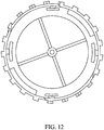
- the brushroll 16 additionally comprises a circumference C ( FIG. 12 ) and the grooves 22 may be spaced evenly around the circumference C. Unevenly spaced grooves 22 are also contemplated.
- the first, second and third recess 24, 25, 26 all receive a first type (i.e., a same type) of material.
- the first recess 24 receives the first material 24A
- the second and third recesses 25, 26 receive the second material 25A.
- the first, second, and third cleaning materials 24A, 25A, and 26A are received and/or attached directly on the body 20 of the brushroll 16 and connected with a fastener (e.g., a glue, an adhesive, a hook and loop fastener, and/or the like).
- the first recess 24 has a first width 27 ( FIG. 8 ) and follows a V-shaped path that extends or wraps around the circumference C of the body 20.
- the second and third recesses 25, 26 each have a second width 28 ( Fig. 8 ).
- the first width 27 (see, e.g., FIGS. 8 and 12 ) is a length of an arc extending between a top and bottom of the first recess 24 along a line normal to the axis 17.
- the second width 28 (shown in FIGS. 8 and 12 ) is a length of an arc extending between a top and bottom of the second and/or third recesses 25 and 26 along a line normal to the axis 17.
- the second width 28 may be relatively narrow compared to the relatively wide first width 27.
- the second and third recesses 25, 26 may be located on opposite sides of the first recess 24.
- the first recess 24 may be disposed between the second recess 24 and third recess 26 and each of the recesses 24, 25, 26 may follow and/or be formed as a V-shaped path.
- the path of the first material 24A may be substantially the same as the path of the first recess 24, the path of the second material 25A may be substantially the same as the path of the second recess 25, and the path of the third material 26A may be substantially the same as the path of the third recess 26.
- the first, second and third material 24A, 25A, 26A may be received directly on the body 20 of the brushroll 16 and connected with a fastener rather than received in a first, second, or third recesses 24, 25, 26, respectively.
- the first material 24A may be formed from a plush cloth material. Other materials (e.g. non-plush materials) may also be used as the first material 24A in some embodiments.
- the second material 25A may include and/or be formed as a row of bristles.
- the third material 26A may include a row of bristles.
- the second and third materials 25A and 26A may include different types of bristles (e.g., bristles having different lengths, diameters, and/or the like) and/or bristles comprised of different materials.
- the bristles may include and/or be formed as nylon bristles.
- the first material 24A may include a first length and is configured for collecting a first type of debris (e.g., dirt, dust, powder, glitter, particulates, and/or the like).
- the second and third material 25A, 26A may have a second length that is greater than the first length and are configured for collecting a second type of debris (e.g., hair, hay, thread, string, and/or the like).
- the inflection point 20C lies along the axis 17 and is about equidistant between the first end 20A and the second end 20B.
- the first material 24A protrudes in a radial direction away from the brushroll 16 and extends between the first end 20A and the second end 20B.
- the path of the first material 24A wraps around the brushroll 16 with a pitch P ( FIG. 9 ) relative to the axis 17. Between the first end 20A and the inflection point 20C, the path of the first material 24A wraps in a first direction (i.e., clockwise).
- the path of the first material 24A wraps in a second direction (i.e., counter-clockwise).
- the pitch P of the path of first material 24A wrapping in the clockwise direction flips such that the pitch P of the path of first material 24A wrapping in the counter-clockwise direction is equal and opposite, or substantially equal and opposite.
- the V-shaped path extends between the first end 20A and the second end 20B, and the inflection point 20C represents the tip of the letter "V" where the V-shaped path changes direction.
- the first, second, and third recesses 24, 25, 26 and the first, second, and/or third materials 24A, 25A, 26A disposed in the recesses may each follow the V-shaped path as described in the illustrated embodiment.
- each of the first, second, and third recesses 24, 25, 26 are duplicated at least once around the brushroll 16.
- the first, second, and third recess 24, 25, 26 are duplicated multiple times around the brushroll 16.
- the illustrated brushroll 16 further includes the wall 23 which extends in a radial direction away from the body 20 and follows a sloped path around the brushroll 16.
- the wall 23 extends between the first end 20A and the second end 20B and wraps around the brushroll 16 about the axis 17.
- the direction of the sloped path about the axis 17 reverses at the inflection point 20C.
- the sloped path of the wall 23 substantially follows the path of the first material 24A around the brushroll 16.
- the sloped path has the pitch P angle that remains constant as the wall 23 wraps clockwise around the brushroll 16 between the first end 20A and the inflection point 20C. At the inflection point 20C, the pitch P angle changes by about 90 degrees relative to the axis 17.
- the wall 23 between the first end 20A and the inflection point 20C is substantially the same as the wall 23 between the inflection point 20C and the second end 20B when mirrored across the inflection point 20C along the axis 17.
- an entire outer surface of the body 20 is covered by the first material 24A, second material 25A, third material 26A and the wall 23. Meaning that when the materials 24A, 25A, 26A are received on the brushroll 16, none of the outer surface of the body is exposed.
- some of the body 20 e.g., a portion of the body 20
- the entire outer surface of the body 20 is covered by only the first material 24A and the wall 23.
- FIGS. 8 and 9 illustrate the brushroll 16 with the first, second, and third material 24A, 25A, 26A removed from the brushroll 16 to reveal the body 20, grooves 22, wall 23 and the first, second, and third recess 24, 25, 26.
- FIGS. 8 and 9 illustrate the wall 23 and the first, second, and third recesses 24, 25, 26 each following substantially the same V-shaped path.
- the wall 23 starts at one point of, on, or around the circumference C of the brushroll 16 and the first recess 24 starts at a different point of, on, or around the circumference C of the brushroll 16.
- a third width 72 (shown in FIGS. 8 and 12 ) is a width of the wall 23.
- the third width 72 is an arc having a length between a top and bottom of the wall 23 along a line normal to the axis 17.
- the first width 27, second width 28 and third width 72 may each remain substantially consistent regardless of where the width is being measured along the axis 17, in some embodiments.
- the base 12 may additionally include wheels 30, support rollers 34, a motor 38, a driving mechanism 42, a suction opening 44, a suction inlet 46 and roller support assembly 48.
- the wheels 30 and the support rollers 34 enable the base 12 to be moved along a surface to be cleaned.
- the handle 11 of FIG. 1 includes a power source 50 operable to generate a suction airflow through the vacuum cleaner 10. The suction airflow is brought in to the base 12 through the suction opening 44 and enters the vacuum cleaner 10 through the suction inlet 46.
- the power source 50 is located in the base 12. With specific reference to FIG. 4 , the motor 38 rotates the drive mechanism 42 for rotating the brushroll 16.
- the base 12 of the illustrated embodiment further includes a cap or cover 54.
- the cover 54 may be removably attached to the housing 14.
- the cover 54 includes a cover handle 58 that can be grabbed by a user using their thumb and index finger in one method of operation.
- the cover 54 may be rotated (e.g. about one-quarter turn) relative to the housing 14 by the user to release or unlock the cover 54. This allows the user to pull the cover 54 away from the base 12 to access and remove the brushroll 16.
- FIGS. 6 and 7 illustrate the housing 14 further including an aperture 60 and a radial groove 62 and the cap 54 including a tab 66.
- the tab 66 corresponds to the radial groove 62 for interlocking the cap 54 to the housing 14 and thereby securing the brushroll 16 in the housing 14.
- the aperture 60 may be substantially circular and include teeth 70 that are spaced circumferentially around the aperture 60.
- the teeth 70 may protrude away from the aperture in a direction toward the second end 20B of the brushroll 16 and parallel to the axis 17.
- the teeth 70 are configured to align with the spacing of the grooves 22 along the brushroll 16 to collect debris (e.g., hair, dirt, dust, and/or the like) as the brushroll 16 is being removed from the base 12 through the aperture 60.
- the teeth 70 need not align with the grooves 22 to collect debris.
- the body 20 may not include the grooves 22 and the teeth 70 still collect debris.
- the teeth 70 each have a similar size and shape that correspond with a similar size and shape of the grooves 22.
- the teeth 70 also collect debris as the brushroll 16 is being used.
- the teeth 70 are also configured to collect elongated debris that would otherwise be missed by the brushroll 16. In this way, the brushroll 16 may be more easily cleaned and/or maintained.
- the grooves 22 also provide a guide or path for a knife, scissors or other cutting instrument to glide over and remove hair or other debris. The user can move the cutting instrument along the grooves 22 while the grooves 22 guide the movement to cut or otherwise loosen any debris, including hair, which is wrapped around or on the brushroll 16.
- the cover 54 is attached to the brushroll 16 so that the cover 54 may be pulled to pull the brushroll 16 through the aperture 60. That is, the brushroll 16 may be removed along with the cover 54.
- the cover 54 may be rotatable within the aperture 60 relative to the brushroll 16 to align with the radial groove 62 to lock and unlock the cover 54 from the housing 14.
- the base 12 further includes an end cap 74 located at the second end 20B of the brushroll 16.
- the end cap 74 may be chamfered or angled toward the brushroll 16 and covers bearing 78 that facilitates rotation of the brushroll 16.
- the angled or chamfered end cap 74 has been found to minimize the amount of hair and other debris that interferes with rotation of the brushroll 16 and the bearing 78.
- the housing 14 may additionally include a plug 82, and a gear 86.
- the plug 82 includes slots 90 that engage with internal blades 94 of the brushroll 16 such that the plug 82 rotates with the brushroll 16.
- the plug 82 further includes a circular opening 98 for receiving a shaft 102 connected to the cover 54 and the circular opening 98 includes a stopper 106 for preventing the cap 54 from being removed from the plug 82.
- the cover 54 may be separated from the plug 82.
- the plug 82 is fixed to the brushroll 16 and the cover 54 is fixed to the plug.
- the gear 86 includes gear teeth 110 that engage with roller teeth 114 on the inside of the brushroll 16.
- the gear 86 is driven by the driving mechanism 42 which rotates the gear teeth 110 to engage the roller teeth 114 to rotate the brushroll 16 relative to the base 12.
Landscapes
- Engineering & Computer Science (AREA)
- Mechanical Engineering (AREA)
- Nozzles For Electric Vacuum Cleaners (AREA)
Abstract
Description
- The present invention relates to vacuum cleaners and more particularly to brushrolls for vacuum cleaners.
- Vacuum cleaners are commonly used for collecting dirt and debris from surface to be cleaned. Some existing vacuum cleaner includes a brushroll with bristles formed in tufts. The brushroll can be rotated to assist picking up dirt and debris from the surface.
- In a first aspect, there is provided a brushroll for a vacuum cleaner. The brushroll includes a first end, a second end, an inflection point located along the axis between the first end and the second end, and a first material that protrudes in a radial direction away from the brushroll. The first material, having a first width, extends between the first end and the second end and wraps around the brushroll with a pitch relative to the axis. The first material wraps in a first direction between the first end and the inflection point and wraps in a second direction between the inflection point and the second end. The pitch of the first material that wraps in the first direction is opposite to the pitch of the first material that wraps in the second direction.
- In one embodiment of the first aspect, the inflection point is about equidistant between the first end and the second end.
- In one embodiment of the first aspect, the first material is received in a first recess, the first material has a first length configured for collecting a first type of debris from the surface to be cleaned.
- In one embodiment of the first aspect, the brushroll further includes a second material protruding radially away from the brushroll and having a second width greater than the first width, the second material received in a second recess and a third recess. The first recess is between the second recess and the third recess.
- In one embodiment of the first aspect, the second material have a second length greater than the first length and are configured for collecting a second type of debris from the surface to be cleaned.
- In one embodiment of the first aspect, the first material is a plush cloth and the second material is a row of bristles.
- In one embodiment of the first aspect, the first recess has a "v" shaped path wrapped around the brushroll such that the "v" shaped path extends between the first end and the second end, and the inflection point corresponds to a tip of the letter "v" where the "v" shaped path changes directions.
- In one embodiment of the first aspect, the second recess and the third recess follow the "v" shaped path.
- In one embodiment of the first aspect, the pitch of the first recess relative to the axis remains constant as the first recess wraps clockwise around the brushroll between the first end and the inflection point, and at the inflection point the pitch of the first recess relative to the axis changes direction, and the pitch of the first recess relative to the axis remains constant as the first recess wraps counter-clockwise around the brushroll between the inflection point and the second end.
- In one embodiment of the first aspect, the brushroll further includes a wall extending radially away from the brushroll, the wall having the "v" shaped path and adjacent to the first recess such that an entire area of an outer diameter of the brushroll is covered by the wall and the first and second material.
- In a second aspect, there is provided a brushroll for a vacuum cleaner. The brushroll includes a body, a first end, a second end, an inflection point located along the axis between the first end and the second end, a wall that extends in a radial direction away from the body, and grooves along the wall. The wall follows a sloped path around the brushroll between the first end and the second end and wraps around the brushroll about the axis. The direction of the sloped path around the body reverses at the inflection point. The grooves along the wall extend along a length of the brushroll between the first end and the second end and are spaced around a circumference of the brushroll.
- In one embodiment of the second aspect, the inflection point is about equidistant between the first end and the second end.
- In one embodiment of the second aspect, the brushroll supports a first cleaning material configured to collect a first type of debris from the surface to be cleaned and a second cleaning material configured to collect a second type of debris from the surface to be cleaned.
- In one embodiment of the second aspect, the first cleaning material is received in a wide first recess following the sloped path of the wall. The second cleaning material is received in a narrow second and third recess following the sloped path of the wall. The wide first recess is between the narrow second and third recess.
- In one embodiment of the second aspect, the sloped path is a "v" shaped path wrapped around the brushroll such that the "v" shaped path extends between the first and second end and the inflection point corresponds to a tip of the letter "v" where the "v" shaped path changes directions.
- In one embodiment of the second aspect, the sloped path of the wall has a pitch angle relative to the axis, the pitch angle remains constant as the wall wraps clockwise around the brushroll between the first end and the inflection point, at the inflection point the pitch angle changes by about 90 degrees relative to the axis, and as the wall wraps counter-clockwise around the brushroll between the inflection point and the second end the pitch angle remains constant.
- In one embodiment of the second aspect, the sloped path of the wall between the first end and the inflection point mirrored across the inflection point nearly equals the sloped path of the wall between the inflection point and the second end.
- In one embodiment of the second aspect, the grooves extend inwardly on the wall toward the center of the brushroll and the grooves are spaced equally around an entire circumference the brushroll.
- In one embodiment of the second aspect, the first and second cleaning material follow the "v" shaped path and are adjacent to the wall such that an entire area of an outer diameter of the brushroll is covered by the wall and the first cleaning material and the second cleaning material.
- In a third aspect, there is provided a vacuum cleaner comprising a base having a suction opening and a brushroll. The base is configured to be moved along a surface to be cleaned. The brushroll is a brushroll of the first aspect or the second aspect. The brushroll is arranged to be positioned within the base and rotatable relative to the base about the axis.
- In a fourth aspect, there is provided a vacuum cleaner that includes a base, a brushroll that is removable from and insertable into the base. The base has an aperture though which the brushroll is removed and inserted. The base has a suction opening and is configured to move along a surface to be cleaned. The brushroll is rotatable relative to the base about an axis, and the brushroll includes a body, a first end, and a second end. The aperture includes teeth that are spaced around a circumference of the aperture. The teeth protrude parallel with axis and away from the aperture towards the brushroll. The teeth of the aperture align with the body of the brushroll to collect debris from the brushroll as the brushroll is being removed from the base through the aperture.
- In one embodiment of the fourth aspect, the brushroll further includes grooves extending in parallel with the axis along the body between the first end and the second end, and wherein the grooves are spaced around a circumference of the brushroll and configured to align with the teeth.
- Other aspects of the present invention will become apparent by consideration of the detailed description and accompanying drawings.
-
-
FIG. 1 is a perspective view of a vacuum cleaner according to an embodiment of the invention. -
FIG. 2 is a perspective view of a base of the vacuum cleaner ofFIG. 1 . -
FIG. 3 is a bottom perspective view of the base ofFIG. 2 . -
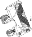
FIG. 4 is a bottom perspective view of the base illustrating inner components of the base. -
FIG. 5 is a perspective view of the base illustrating a brushroll partially removed from the base. -
FIG. 6 is a front perspective view of a portion of the base illustrating a cap removable from the base. -
FIG. 7 is a rear perspective view of a portion of the base illustrating the cap ofFIG. 6 . -
FIG. 8 is a top view of the brushroll ofFIG. 5 . -
FIG. 9 is a front view of the brushroll ofFIG. 5 . -
FIG. 10 is an exploded perspective view of the brushroll and a portion of the base. -
FIG. 11 is a cross-sectional view of the brushroll and a portion of the base taken through the center of the brushroll. -
FIG. 12 is a left-side view of the brushroll. -
FIG. 13 is a right-side view of the brushroll and a portion of the base. -
FIG. 14 is a right-side view of the brushroll. - Before any embodiments of the present invention are explained in detail, it is to be understood that the present invention is not limited in its application to the details of construction and the arrangement of components set forth in the following description or illustrated in the following drawings. The present invention is capable of other embodiments and of being practiced or of being carried out in various ways.
-
FIG. 1 illustrates a vacuum cleaner 10 according to an embodiment of the present invention. The vacuum cleaner 10 includes a handle 11, a floor nozzle or base 12, and a shaft 13 for connecting the handle 11 to the base 12. The base 12 includes a housing 14 and a brushroll or beater bar 16 that rotates relative to the base 12 about an axis 17 (FIG. 2 ) that extends along a length of the brushroll 16 and through a center of the brushroll 16. In the illustrated embodiment, the base 12 includes a window 18 that allows the user to view the brushroll 16 within the base 12. The window 18 may be transparent, or semi-transparent, in some cases. - Referring to
FIG. 2 , the brushroll 16 includes a body 20 that has a first end 20A, a second end 20B, and an inflection point 20C substantially in the middle of the first end 20A and the second end 20B. The details of the inflection point 20C are described further below. The body 20 may be formed, at least partially, from a rubber or plastic material in some embodiments. The body 20 may include a plurality of grooves 22, a wall 23, a first recess 24 for receiving a first cleaning material 24A, a second recess 25 for receiving a second cleaning material 25A, and a third recess 26 for receiving a third cleaning material 26A. As used herein, the term cleaning material refers to materials configured for cleaning, such as, for example, a textile (e.g., woven, non-woven materials) configured for cleaning, a specific fabric configured for cleaning, a bristle configured for cleaning, a foam material configured for cleaning, an electrostatic material configured for cleaning, and/or the like. The grooves 22 may extend into the wall 23 along the length of the body 20 between the first end 20A and the second end 20B. The brushroll 16 additionally comprises a circumference C (FIG. 12 ) and the grooves 22 may be spaced evenly around the circumference C. Unevenly spaced grooves 22 are also contemplated. In some embodiments, the first, second and third recess 24, 25, 26 all receive a first type (i.e., a same type) of material. In the illustrated embodiment, the first recess 24 receives the first material 24A, and the second and third recesses 25, 26 receive the second material 25A. In yet another embodiment, the first, second, and third cleaning materials 24A, 25A, and 26A are received and/or attached directly on the body 20 of the brushroll 16 and connected with a fastener (e.g., a glue, an adhesive, a hook and loop fastener, and/or the like). - With continued reference to
FIG. 2 , the first recess 24 has a first width 27 (FIG. 8 ) and follows a V-shaped path that extends or wraps around the circumference C of the body 20. The second and third recesses 25, 26 each have a second width 28 (Fig. 8 ). The first width 27 (see, e.g.,FIGS. 8 and12 ) is a length of an arc extending between a top and bottom of the first recess 24 along a line normal to the axis 17. The second width 28 (shown inFIGS. 8 and12 ) is a length of an arc extending between a top and bottom of the second and/or third recesses 25 and 26 along a line normal to the axis 17. The second width 28 may be relatively narrow compared to the relatively wide first width 27. The second and third recesses 25, 26 may be located on opposite sides of the first recess 24. The first recess 24 may be disposed between the second recess 24 and third recess 26 and each of the recesses 24, 25, 26 may follow and/or be formed as a V-shaped path. - In the illustrated embodiment, the path of the first material 24A may be substantially the same as the path of the first recess 24, the path of the second material 25A may be substantially the same as the path of the second recess 25, and the path of the third material 26A may be substantially the same as the path of the third recess 26. In another embodiment, the first, second and third material 24A, 25A, 26A may be received directly on the body 20 of the brushroll 16 and connected with a fastener rather than received in a first, second, or third recesses 24, 25, 26, respectively.
- Referring now to
FIGS. 2 - 4 , the first material 24A may be formed from a plush cloth material. Other materials (e.g. non-plush materials) may also be used as the first material 24A in some embodiments. The second material 25A may include and/or be formed as a row of bristles. The third material 26A may include a row of bristles. The second and third materials 25A and 26A may include different types of bristles (e.g., bristles having different lengths, diameters, and/or the like) and/or bristles comprised of different materials. In one embodiment, the bristles may include and/or be formed as nylon bristles. The first material 24A may include a first length and is configured for collecting a first type of debris (e.g., dirt, dust, powder, glitter, particulates, and/or the like). The second and third material 25A, 26A may have a second length that is greater than the first length and are configured for collecting a second type of debris (e.g., hair, hay, thread, string, and/or the like). - The details regarding the inflection point 20C will now be described with reference to the V-shaped path. In some embodiments, the inflection point 20C lies along the axis 17 and is about equidistant between the first end 20A and the second end 20B. The first material 24A protrudes in a radial direction away from the brushroll 16 and extends between the first end 20A and the second end 20B. The path of the first material 24A wraps around the brushroll 16 with a pitch P (
FIG. 9 ) relative to the axis 17. Between the first end 20A and the inflection point 20C, the path of the first material 24A wraps in a first direction (i.e., clockwise). Between the inflection point 20C and the second end 20B, the path of the first material 24A wraps in a second direction (i.e., counter-clockwise). At the inflection point 20C, the pitch P of the path of first material 24A wrapping in the clockwise direction flips such that the pitch P of the path of first material 24A wrapping in the counter-clockwise direction is equal and opposite, or substantially equal and opposite. - In the illustrated embodiment, the V-shaped path extends between the first end 20A and the second end 20B, and the inflection point 20C represents the tip of the letter "V" where the V-shaped path changes direction. The first, second, and third recesses 24, 25, 26 and the first, second, and/or third materials 24A, 25A, 26A disposed in the recesses may each follow the V-shaped path as described in the illustrated embodiment. In the illustrated embodiment, each of the first, second, and third recesses 24, 25, 26 are duplicated at least once around the brushroll 16. In another embodiment, the first, second, and third recess 24, 25, 26 are duplicated multiple times around the brushroll 16.
- The illustrated brushroll 16 further includes the wall 23 which extends in a radial direction away from the body 20 and follows a sloped path around the brushroll 16. The wall 23 extends between the first end 20A and the second end 20B and wraps around the brushroll 16 about the axis 17. The direction of the sloped path about the axis 17 reverses at the inflection point 20C. The sloped path of the wall 23 substantially follows the path of the first material 24A around the brushroll 16. The sloped path has the pitch P angle that remains constant as the wall 23 wraps clockwise around the brushroll 16 between the first end 20A and the inflection point 20C. At the inflection point 20C, the pitch P angle changes by about 90 degrees relative to the axis 17. As the wall 23 wraps counter clockwise around the brushroll 16 between the inflection point 20C and the second end 20B, the pitch P angle remains constant. The wall 23 between the first end 20A and the inflection point 20C is substantially the same as the wall 23 between the inflection point 20C and the second end 20B when mirrored across the inflection point 20C along the axis 17. In the illustrated embodiment, an entire outer surface of the body 20 is covered by the first material 24A, second material 25A, third material 26A and the wall 23. Meaning that when the materials 24A, 25A, 26A are received on the brushroll 16, none of the outer surface of the body is exposed. In another embodiment, some of the body 20 (e.g., a portion of the body 20) is exposed or uncovered. In yet another embodiment, the entire outer surface of the body 20 is covered by only the first material 24A and the wall 23.
-
FIGS. 8 and 9 illustrate the brushroll 16 with the first, second, and third material 24A, 25A, 26A removed from the brushroll 16 to reveal the body 20, grooves 22, wall 23 and the first, second, and third recess 24, 25, 26.FIGS. 8 and 9 illustrate the wall 23 and the first, second, and third recesses 24, 25, 26 each following substantially the same V-shaped path. The wall 23 starts at one point of, on, or around the circumference C of the brushroll 16 and the first recess 24 starts at a different point of, on, or around the circumference C of the brushroll 16. A third width 72 (shown inFIGS. 8 and12 ) is a width of the wall 23. The third width 72 is an arc having a length between a top and bottom of the wall 23 along a line normal to the axis 17. The first width 27, second width 28 and third width 72 may each remain substantially consistent regardless of where the width is being measured along the axis 17, in some embodiments. - Referring now to
FIGS. 3 and4 , the base 12 may additionally include wheels 30, support rollers 34, a motor 38, a driving mechanism 42, a suction opening 44, a suction inlet 46 and roller support assembly 48. The wheels 30 and the support rollers 34 enable the base 12 to be moved along a surface to be cleaned. The handle 11 ofFIG. 1 includes a power source 50 operable to generate a suction airflow through the vacuum cleaner 10. The suction airflow is brought in to the base 12 through the suction opening 44 and enters the vacuum cleaner 10 through the suction inlet 46. In another embodiment the power source 50 is located in the base 12. With specific reference toFIG. 4 , the motor 38 rotates the drive mechanism 42 for rotating the brushroll 16. - With reference to
FIGS. 5-7 , the base 12 of the illustrated embodiment further includes a cap or cover 54. The cover 54 may be removably attached to the housing 14. The cover 54 includes a cover handle 58 that can be grabbed by a user using their thumb and index finger in one method of operation. In one embodiment, the cover 54 may be rotated (e.g. about one-quarter turn) relative to the housing 14 by the user to release or unlock the cover 54. This allows the user to pull the cover 54 away from the base 12 to access and remove the brushroll 16.FIGS. 6 and 7 illustrate the housing 14 further including an aperture 60 and a radial groove 62 and the cap 54 including a tab 66. The tab 66 corresponds to the radial groove 62 for interlocking the cap 54 to the housing 14 and thereby securing the brushroll 16 in the housing 14. - With continued reference to
FIGS. 6 and 7 , the aperture 60 may be substantially circular and include teeth 70 that are spaced circumferentially around the aperture 60. The teeth 70 may protrude away from the aperture in a direction toward the second end 20B of the brushroll 16 and parallel to the axis 17. The teeth 70 are configured to align with the spacing of the grooves 22 along the brushroll 16 to collect debris (e.g., hair, dirt, dust, and/or the like) as the brushroll 16 is being removed from the base 12 through the aperture 60. In another embodiment, the teeth 70 need not align with the grooves 22 to collect debris. In yet another embodiment, the body 20 may not include the grooves 22 and the teeth 70 still collect debris. The teeth 70 each have a similar size and shape that correspond with a similar size and shape of the grooves 22. In the illustrated embodiment, the teeth 70 also collect debris as the brushroll 16 is being used. The teeth 70 are also configured to collect elongated debris that would otherwise be missed by the brushroll 16. In this way, the brushroll 16 may be more easily cleaned and/or maintained. The grooves 22 also provide a guide or path for a knife, scissors or other cutting instrument to glide over and remove hair or other debris. The user can move the cutting instrument along the grooves 22 while the grooves 22 guide the movement to cut or otherwise loosen any debris, including hair, which is wrapped around or on the brushroll 16. - In some embodiments, the cover 54 is attached to the brushroll 16 so that the cover 54 may be pulled to pull the brushroll 16 through the aperture 60. That is, the brushroll 16 may be removed along with the cover 54. In such an embodiment, the cover 54 may be rotatable within the aperture 60 relative to the brushroll 16 to align with the radial groove 62 to lock and unlock the cover 54 from the housing 14.
- Referring now to
FIGS. 10 to 14 , the base 12 further includes an end cap 74 located at the second end 20B of the brushroll 16. The end cap 74 may be chamfered or angled toward the brushroll 16 and covers bearing 78 that facilitates rotation of the brushroll 16. The angled or chamfered end cap 74 has been found to minimize the amount of hair and other debris that interferes with rotation of the brushroll 16 and the bearing 78. - The housing 14 may additionally include a plug 82, and a gear 86. The plug 82 includes slots 90 that engage with internal blades 94 of the brushroll 16 such that the plug 82 rotates with the brushroll 16. In the illustrated embodiment, the plug 82 further includes a circular opening 98 for receiving a shaft 102 connected to the cover 54 and the circular opening 98 includes a stopper 106 for preventing the cap 54 from being removed from the plug 82. In another embodiment, the cover 54 may be separated from the plug 82. In still another embodiment, the plug 82 is fixed to the brushroll 16 and the cover 54 is fixed to the plug.
- The gear 86 includes gear teeth 110 that engage with roller teeth 114 on the inside of the brushroll 16. The gear 86 is driven by the driving mechanism 42 which rotates the gear teeth 110 to engage the roller teeth 114 to rotate the brushroll 16 relative to the base 12.
- Although the present invention has been described in detail with reference to certain preferred embodiments, variations and modifications exist within the scope of one or more independent aspects of the invention as described.
Claims (15)
- A brushroll for a vacuum cleaner, comprising:a first end;a second end;an inflection point located along an axis between the first end and the second end; anda first material protruding radially away from the brushroll and having a first width, the first material extending between the first end and the second end, the first material wrapping around the brushroll with a pitch relative to the axis, and the first material wrapping in a first direction between the first end and the inflection point and wrapping in a second direction between the inflection point and the second end,wherein the pitch of the first material wrapping in the first direction is opposite to the pitch of the first material wrapping in the second direction.
- The brushroll of claim 1, wherein the inflection point is about equidistant between the first end and the second end.
- The brushroll of claim 1 or 2, wherein the first material is received in a first recess, the first material has a first length configured for collecting a first type of debris from the surface to be cleaned.
- The brushroll of claim 3, further including a second material protruding radially away from the brushroll and having a second width greater than the first width, the second material received in a second recess and a third recess, and wherein the first recess is between the second recess and the third recess, and optionally, the second material have a second length greater than the first length and is configured for collecting a second type of debris from the surface to be cleaned, and optionally, the first material is a plush cloth and the second material is a row of bristles.
- The brushroll of claim 4, wherein the first recess has a "v" shaped path wrapped around the brushroll such that the "v" shaped path extends between the first end and the second end, and the inflection point corresponds to a tip of the letter "v" where the "v" shaped path changes directions, and optionally, wherein the second recess and the third recess follow the "v" shaped path.
- The brushroll of claim 5, wherein the pitch of the first recess relative to the axis remains constant as the first recess wraps clockwise around the brushroll between the first end and the inflection point, and at the inflection point the pitch of the first recess relative to the axis changes direction, and the pitch of the first recess relative to the axis remains constant as the first recess wraps counter-clockwise around the brushroll between the inflection point and the second end.
- The brushroll of claim 5, further including a wall extending radially away from the brushroll, the wall having the "v" shaped path and adjacent to the first recess such that an entire area of an outer diameter of the brushroll is covered by the wall and the first material and the second material.
- A brushroll for a vacuum cleaner, comprising:a body;a first end;a second end;an inflection point disposed along an axis between the first end and the second end;a wall extending radially away from the body, the wall following a sloped path around the brushroll between the first end and the second end, and the wall wrapping around the brushroll about the axis, wherein a direction of the sloped path around the brushroll reverses at the inflection point; andgrooves along the wall, extending along a length of the brushroll between the first end and the second end, wherein the grooves are spaced around a circumference of the brushroll, and optionally, wherein the inflection point is about equidistant between the first end and the second end.
- The brushroll of claim 8, wherein the brushroll supports a first cleaning material configured to collect a first type of debris from the surface to be cleaned and a second cleaning material configured to collect a second type of debris from the surface to be cleaned.
- The brushroll of claim 9, wherein the first cleaning material is received in a wide first recess following the sloped path of the wall, and wherein the second cleaning material is received in a narrow second and third recesses following the sloped path of the wall, and wherein the wide first recess is between the narrow second and third recesses.
- The brushroll of claim 9 or 10, wherein the sloped path is a "v" shaped path wrapped around the brushroll such that the "v" shaped path extends between the first and second end and the inflection point corresponds to a tip of the letter "v" where the "v" shaped path changes directions, and optionally, wherein the sloped path of the wall has a pitch angle relative to the axis, the pitch angle remains constant as the wall wraps clockwise around the brushroll between the first end and the inflection point, at the inflection point the pitch angle changes by about 90 degrees relative to the axis, and as the wall wraps counter-clockwise around the brushroll between the inflection point and the second end the pitch angle remains constant, and optionally, wherein the sloped path of the wall between the first end and the inflection point mirrored across the inflection point nearly equals the sloped path of the wall between the inflection point and the second end.
- The brushroll of claim any one of claims 8 to 11, wherein the grooves extend inwardly on the wall toward the center of the brushroll and the grooves are spaced equally around an entire circumference the brushroll.
- The brushroll of claim 12, wherein the first and second cleaning material follow the "v" shaped path and are adjacent to the wall such that an entire area of an outer diameter of the brushroll is covered by the wall and the first cleaning material and the second cleaning material.
- A vacuum cleaner comprising:a base having a suction opening, the base being configured to be moved along a surface to be cleaned; anda brushroll of any one of the preceding claims, the brushroll being arranged to be positioned within the base and rotatable relative to the base about the axis.
- A vacuum cleaner comprising:a base having a suction opening, the base being configured to move along a surface to be cleaned; anda brushroll being removable from and insertable into the base and rotatable about an axis, the brushroll including:a body;a first end; anda second end;wherein the base includes an aperture through which the brushroll can be inserted and removed, the aperture including teeth spaced around a circumference of the aperture, the teeth protruding parallel with the axis and away from the aperture towards the brushroll and for aligning with the body, and the teeth being configured to collect debris from the brushroll as the brushroll is removed from the base through the aperture, and optionally, the brushroll further includes grooves extending in parallel with the axis along the body between the first end and the second end, and wherein the grooves are spaced around a circumference of the brushroll and configured to align with the teeth.
Applications Claiming Priority (1)
| Application Number | Priority Date | Filing Date | Title |
|---|---|---|---|
| US201862741440P | 2018-10-04 | 2018-10-04 |
Publications (2)
| Publication Number | Publication Date |
|---|---|
| EP3632281A1 true EP3632281A1 (en) | 2020-04-08 |
| EP3632281B1 EP3632281B1 (en) | 2022-07-20 |
Family
ID=68158953
Family Applications (1)
| Application Number | Title | Priority Date | Filing Date |
|---|---|---|---|
| EP19201504.8A Active EP3632281B1 (en) | 2018-10-04 | 2019-10-04 | Vacuum cleaner |
Country Status (5)
| Country | Link |
|---|---|
| US (2) | US11638507B2 (en) |
| EP (1) | EP3632281B1 (en) |
| CN (1) | CN212521642U (en) |
| AU (1) | AU2019101214A6 (en) |
| CA (1) | CA3057474A1 (en) |
Families Citing this family (4)
| Publication number | Priority date | Publication date | Assignee | Title |
|---|---|---|---|---|
| ES2898279A1 (en) * | 2020-09-04 | 2022-03-04 | Cecotec Res And Development Sl | Roller brush for cleaning apparatus |
| CN112998605B (en) * | 2021-02-26 | 2022-12-09 | 北京享捷科技有限公司 | Multifunctional maintenance station of sweeping robot |
| GB2606154B (en) * | 2021-04-26 | 2023-12-27 | Dyson Technology Ltd | Brushbar for a vacuum cleaner |
| CN113854908B (en) * | 2021-09-30 | 2022-12-23 | 易宝软件有限公司 | Self-cleaning method of floor cleaning machine, electronic equipment and computer storage medium |
Citations (3)
| Publication number | Priority date | Publication date | Assignee | Title |
|---|---|---|---|---|
| DE594234C (en) * | 1932-04-23 | 1934-03-14 | Hoover Co | Suction hood of a vacuum cleaner with a rotating body arranged in it |
| GB1023556A (en) * | 1963-11-12 | 1966-03-23 | Thomas Lowther Whitehead | Machine for cleaning carpets and floors |
| DE1967828U (en) * | 1966-10-13 | 1967-09-07 | Buerstenfabrik Walther A G | CARPET AND FLOOR CLEANER. |
Family Cites Families (44)
| Publication number | Priority date | Publication date | Assignee | Title |
|---|---|---|---|---|
| US2300267A (en) | 1940-05-16 | 1942-10-27 | Hoover Co | Suction cleaner brush |
| DE2729266A1 (en) * | 1977-06-29 | 1979-01-18 | Duepro Ag | CLEANING DEVICE |
| US4307479A (en) | 1979-10-19 | 1981-12-29 | Superior Brush Company | Angle tufted rotary brush assembly |
| JPH02104321A (en) | 1988-10-13 | 1990-04-17 | Hookii:Kk | Rotary brush |
| DK0822774T3 (en) | 1995-04-21 | 2002-07-15 | Vorwerk Co Interholding | Suction accessory part for moisturizing surfaces |
| US6108853A (en) * | 1999-02-04 | 2000-08-29 | Dittus; James D. | Vacuum cleaner beater brush |
| US6381801B1 (en) | 2000-05-10 | 2002-05-07 | Clean Up America, Inc. | Self-propelled brushless surface cleaner with reclamation |
| US6532619B2 (en) | 2000-06-19 | 2003-03-18 | Bissell Homecare, Inc. | Extraction cleaner and agitator therefor |
| US7251857B2 (en) | 2002-12-10 | 2007-08-07 | Steven Jerome Caruso | Versatile tools |
| US20080022484A1 (en) | 2000-09-26 | 2008-01-31 | Caruso Steven J | Versatile Tools |
| US6934993B1 (en) | 2001-07-02 | 2005-08-30 | Bissell Homecare, Inc. | Extraction cleaning machine with agitation brushes |
| US6735812B2 (en) | 2002-02-22 | 2004-05-18 | Tennant Company | Dual mode carpet cleaning apparatus utilizing an extraction device and a soil transfer cleaning medium |
| US6859976B2 (en) | 2002-02-22 | 2005-03-01 | S.C. Johnson & Son, Inc. | Cleaning apparatus with continuous action wiping and sweeping |
| JP3970154B2 (en) | 2002-10-28 | 2007-09-05 | 三洋電機株式会社 | Floor suction tool |
| US6754466B1 (en) | 2003-01-08 | 2004-06-22 | Xerox Corporation | Toner removal apparatus for copier or printer |
| JP3849668B2 (en) | 2003-05-19 | 2006-11-22 | 松下電器産業株式会社 | Vacuum cleaner suction tool and vacuum cleaner using the same |
| US20050005389A1 (en) | 2003-07-07 | 2005-01-13 | Minuteman International, Inc. | Floor cleaning machine using micro-fiber pad |
| KR100688612B1 (en) | 2006-01-24 | 2007-03-02 | 삼성광주전자 주식회사 | Upright vacuum cleaner for cleaning mop |
| KR100751462B1 (en) | 2006-02-13 | 2007-08-23 | 삼성광주전자 주식회사 | Steam cleaner combined with vacuum cleaner |
| EP2548492B1 (en) * | 2006-05-19 | 2016-04-20 | iRobot Corporation | Removing debris from cleaning robots |
| WO2008124914A1 (en) | 2007-04-12 | 2008-10-23 | Superior Industrial Services | Roll cleaning apparatus and method |
| US8083860B2 (en) | 2007-11-27 | 2011-12-27 | The Servicemaster Company | Capture and removal cleaning system |
| JP4913085B2 (en) | 2008-03-04 | 2012-04-11 | オリンパスイメージング株式会社 | Multi-image file editing device, multi-image file editing program, and multi-image file editing method |
| JP2009268684A (en) | 2008-05-07 | 2009-11-19 | Kowa Co Ltd | Rotating rotor, suction tool for vacuum cleaner, vacuum cleaner, and air conditioner |
| GB2470917A (en) * | 2009-06-09 | 2010-12-15 | Dyson Technology Ltd | Agitating means for cleaning head |
| JP5083359B2 (en) * | 2009-11-09 | 2012-11-28 | 三菱電機株式会社 | Vacuum cleaner suction tool |
| JP5589092B2 (en) * | 2010-01-08 | 2014-09-10 | ダイソン テクノロジー リミテッド | Vacuum cleaner head |
| GB2476810B (en) | 2010-01-08 | 2014-01-08 | Dyson Technology Ltd | Cleaner head for a vacuum cleaner |
| GB2481387B (en) | 2010-06-21 | 2014-07-30 | Dyson Technology Ltd | Attachment for a vacuum cleaning appliance |
| US20120110779A1 (en) | 2010-11-04 | 2012-05-10 | Wafertech, Llc | Turbine powered cleaning apparatus |
| US9072415B2 (en) | 2010-11-05 | 2015-07-07 | Bissell Homecare, Inc. | Bare floor vacuum cleaner |
| ES2357490B1 (en) | 2011-03-01 | 2012-02-14 | Dols Industrial De Peluqueria, S.A. | PROCEDURE FOR METALIZATION OF NYLON FIBERS AND BRUSH FOR THE HAIR OF METALLIZED NYLON FIBERS OBTAINED BY MEANS OF SUCH PROCEDURE. |
| US20120311802A1 (en) | 2011-06-10 | 2012-12-13 | Hinnant Andre Lagary | Vacuum cleaner multi-directional brushroll/agitator |
| US9848747B2 (en) | 2013-07-09 | 2017-12-26 | Changsuk Seo | Floor cleaning device |
| GB201313707D0 (en) | 2013-07-31 | 2013-09-11 | Dyson Technology Ltd | Cleaner head for a vacuum cleaner |
| CN203885436U (en) | 2014-01-29 | 2014-10-22 | 创科地板护理技术有限公司 | Additional tool capable of being connected to vacuum dust collector |
| JP6075466B2 (en) * | 2014-02-07 | 2017-02-08 | 三菱電機株式会社 | Floor suction tool and electric vacuum cleaner provided with the floor suction tool |
| JP1536338S (en) | 2014-08-21 | 2015-10-26 | ||
| US9770151B2 (en) | 2015-01-08 | 2017-09-26 | Dongguan Pheaton Electronic Technology Co., Ltd. | Cleaning appliance |
| US9955832B2 (en) * | 2015-01-30 | 2018-05-01 | Sharkninja Operating Llc | Surface cleaning head with removable non-driven agitator having cleaning pad |
| US11647881B2 (en) | 2015-10-21 | 2023-05-16 | Sharkninja Operating Llc | Cleaning apparatus with combing unit for removing debris from cleaning roller |
| AU2016101847B4 (en) | 2015-10-28 | 2022-02-17 | Bissell Inc. | Surface cleaning apparatus |
| US9968234B2 (en) | 2016-06-15 | 2018-05-15 | Hobot Technology Inc. | Automatic cleaning machine |
| CN106419767A (en) * | 2016-07-28 | 2017-02-22 | 太仓文广汇清洁设备有限公司 | Household cleaning equipment |
-
2019
- 2019-09-25 US US16/582,381 patent/US11638507B2/en active Active
- 2019-09-30 CN CN201921662813.1U patent/CN212521642U/en active Active
- 2019-10-03 CA CA3057474A patent/CA3057474A1/en active Pending
- 2019-10-04 AU AU2019101214A patent/AU2019101214A6/en active Active
- 2019-10-04 EP EP19201504.8A patent/EP3632281B1/en active Active
-
2023
- 2023-04-26 US US18/307,612 patent/US20230255417A1/en not_active Abandoned
Patent Citations (3)
| Publication number | Priority date | Publication date | Assignee | Title |
|---|---|---|---|---|
| DE594234C (en) * | 1932-04-23 | 1934-03-14 | Hoover Co | Suction hood of a vacuum cleaner with a rotating body arranged in it |
| GB1023556A (en) * | 1963-11-12 | 1966-03-23 | Thomas Lowther Whitehead | Machine for cleaning carpets and floors |
| DE1967828U (en) * | 1966-10-13 | 1967-09-07 | Buerstenfabrik Walther A G | CARPET AND FLOOR CLEANER. |
Also Published As
| Publication number | Publication date |
|---|---|
| US20200107684A1 (en) | 2020-04-09 |
| AU2019101214A4 (en) | 2019-11-14 |
| EP3632281B1 (en) | 2022-07-20 |
| AU2019101214A6 (en) | 2020-12-24 |
| US20230255417A1 (en) | 2023-08-17 |
| CN212521642U (en) | 2021-02-12 |
| US11638507B2 (en) | 2023-05-02 |
| CA3057474A1 (en) | 2020-04-04 |
Similar Documents
| Publication | Publication Date | Title |
|---|---|---|
| US20230255417A1 (en) | Vacuum cleaner | |
| US11395569B2 (en) | Brushroll for vacuum cleaner | |
| GB2534983B (en) | Brushroll for vacuum cleaner | |
| AU2005243454B2 (en) | Tool for a surface treating appliance | |
| CA3087466C (en) | Brushroll for vacuum cleaner | |
| US20210113039A1 (en) | Vacuum cleaner | |
| KR20210022876A (en) | A vaccum cleaner | |
| CN104837391A (en) | Vacuum cleaner brush | |
| KR20240082943A (en) | Cleaner | |
| WO2010087970A1 (en) | Floor sweeper with ventilation means | |
| US20130042429A1 (en) | Suction tool for vacuum cleaner | |
| JP2019013728A (en) | Brush and rotating brush | |
| US12605022B2 (en) | Brushroll for vacuum cleaner | |
| CN111820813B (en) | Vacuum cleaner head | |
| JP4176601B2 (en) | Suction port and vacuum cleaner | |
| JP4504163B2 (en) | Suction port and vacuum cleaner | |
| JP5624520B2 (en) | Suction port body, rotary cleaning body and vacuum cleaner provided with the same | |
| JP4825563B2 (en) | Rotating cleaning body and electric vacuum cleaner provided with the same | |
| JPH0662989A (en) | Vacuum cleaner | |
| JPS62231611A (en) | Suction tool with rotary brush of electric cleaner | |
| JPH0573413B2 (en) | ||
| WO2022256513A1 (en) | Surface cleaner | |
| JP2024011449A (en) | Cleaning tools and vacuum cleaners |
Legal Events
| Date | Code | Title | Description |
|---|---|---|---|
| PUAI | Public reference made under article 153(3) epc to a published international application that has entered the european phase |
Free format text: ORIGINAL CODE: 0009012 |
|
| STAA | Information on the status of an ep patent application or granted ep patent |
Free format text: STATUS: THE APPLICATION HAS BEEN PUBLISHED |
|
| AK | Designated contracting states |
Kind code of ref document: A1 Designated state(s): AL AT BE BG CH CY CZ DE DK EE ES FI FR GB GR HR HU IE IS IT LI LT LU LV MC MK MT NL NO PL PT RO RS SE SI SK SM TR |
|
| AX | Request for extension of the european patent |
Extension state: BA ME |
|
| STAA | Information on the status of an ep patent application or granted ep patent |
Free format text: STATUS: REQUEST FOR EXAMINATION WAS MADE |
|
| 17P | Request for examination filed |
Effective date: 20201008 |
|
| RAP1 | Party data changed (applicant data changed or rights of an application transferred) |
Owner name: TTI (MACAO COMMERCIAL OFFSHORE) LIMITED |
|
| RBV | Designated contracting states (corrected) |
Designated state(s): AL AT BE BG CH CY CZ DE DK EE ES FI FR GB GR HR HU IE IS IT LI LT LU LV MC MK MT NL NO PL PT RO RS SE SI SK SM TR |
|
| RAP1 | Party data changed (applicant data changed or rights of an application transferred) |
Owner name: TECHTRONIC CORDLESS GP |
|
| GRAP | Despatch of communication of intention to grant a patent |
Free format text: ORIGINAL CODE: EPIDOSNIGR1 |
|
| STAA | Information on the status of an ep patent application or granted ep patent |
Free format text: STATUS: GRANT OF PATENT IS INTENDED |
|
| RIC1 | Information provided on ipc code assigned before grant |
Ipc: A47L 11/40 20060101ALI20220331BHEP Ipc: A47L 11/19 20060101ALI20220331BHEP Ipc: A47L 11/18 20060101ALI20220331BHEP Ipc: A47L 9/04 20060101AFI20220331BHEP |
|
| INTG | Intention to grant announced |
Effective date: 20220422 |
|
| GRAS | Grant fee paid |
Free format text: ORIGINAL CODE: EPIDOSNIGR3 |
|
| GRAA | (expected) grant |
Free format text: ORIGINAL CODE: 0009210 |
|
| STAA | Information on the status of an ep patent application or granted ep patent |
Free format text: STATUS: THE PATENT HAS BEEN GRANTED |
|
| AK | Designated contracting states |
Kind code of ref document: B1 Designated state(s): AL AT BE BG CH CY CZ DE DK EE ES FI FR GB GR HR HU IE IS IT LI LT LU LV MC MK MT NL NO PL PT RO RS SE SI SK SM TR |
|
| REG | Reference to a national code |
Ref country code: CH Ref legal event code: EP |
|
| REG | Reference to a national code |
Ref country code: DE Ref legal event code: R096 Ref document number: 602019017143 Country of ref document: DE |
|
| REG | Reference to a national code |
Ref country code: AT Ref legal event code: REF Ref document number: 1505008 Country of ref document: AT Kind code of ref document: T Effective date: 20220815 |
|
| REG | Reference to a national code |
Ref country code: IE Ref legal event code: FG4D |
|
| REG | Reference to a national code |
Ref country code: LT Ref legal event code: MG9D |
|
| REG | Reference to a national code |
Ref country code: NL Ref legal event code: MP Effective date: 20220720 |
|
| PG25 | Lapsed in a contracting state [announced via postgrant information from national office to epo] |
Ref country code: SE Free format text: LAPSE BECAUSE OF FAILURE TO SUBMIT A TRANSLATION OF THE DESCRIPTION OR TO PAY THE FEE WITHIN THE PRESCRIBED TIME-LIMIT Effective date: 20220720 Ref country code: RS Free format text: LAPSE BECAUSE OF FAILURE TO SUBMIT A TRANSLATION OF THE DESCRIPTION OR TO PAY THE FEE WITHIN THE PRESCRIBED TIME-LIMIT Effective date: 20220720 Ref country code: PT Free format text: LAPSE BECAUSE OF FAILURE TO SUBMIT A TRANSLATION OF THE DESCRIPTION OR TO PAY THE FEE WITHIN THE PRESCRIBED TIME-LIMIT Effective date: 20221121 Ref country code: NO Free format text: LAPSE BECAUSE OF FAILURE TO SUBMIT A TRANSLATION OF THE DESCRIPTION OR TO PAY THE FEE WITHIN THE PRESCRIBED TIME-LIMIT Effective date: 20221020 Ref country code: NL Free format text: LAPSE BECAUSE OF FAILURE TO SUBMIT A TRANSLATION OF THE DESCRIPTION OR TO PAY THE FEE WITHIN THE PRESCRIBED TIME-LIMIT Effective date: 20220720 Ref country code: LV Free format text: LAPSE BECAUSE OF FAILURE TO SUBMIT A TRANSLATION OF THE DESCRIPTION OR TO PAY THE FEE WITHIN THE PRESCRIBED TIME-LIMIT Effective date: 20220720 Ref country code: LT Free format text: LAPSE BECAUSE OF FAILURE TO SUBMIT A TRANSLATION OF THE DESCRIPTION OR TO PAY THE FEE WITHIN THE PRESCRIBED TIME-LIMIT Effective date: 20220720 Ref country code: FI Free format text: LAPSE BECAUSE OF FAILURE TO SUBMIT A TRANSLATION OF THE DESCRIPTION OR TO PAY THE FEE WITHIN THE PRESCRIBED TIME-LIMIT Effective date: 20220720 Ref country code: ES Free format text: LAPSE BECAUSE OF FAILURE TO SUBMIT A TRANSLATION OF THE DESCRIPTION OR TO PAY THE FEE WITHIN THE PRESCRIBED TIME-LIMIT Effective date: 20220720 |
|
| REG | Reference to a national code |
Ref country code: AT Ref legal event code: MK05 Ref document number: 1505008 Country of ref document: AT Kind code of ref document: T Effective date: 20220720 |
|
| PG25 | Lapsed in a contracting state [announced via postgrant information from national office to epo] |
Ref country code: PL Free format text: LAPSE BECAUSE OF FAILURE TO SUBMIT A TRANSLATION OF THE DESCRIPTION OR TO PAY THE FEE WITHIN THE PRESCRIBED TIME-LIMIT Effective date: 20220720 Ref country code: IS Free format text: LAPSE BECAUSE OF FAILURE TO SUBMIT A TRANSLATION OF THE DESCRIPTION OR TO PAY THE FEE WITHIN THE PRESCRIBED TIME-LIMIT Effective date: 20221120 Ref country code: HR Free format text: LAPSE BECAUSE OF FAILURE TO SUBMIT A TRANSLATION OF THE DESCRIPTION OR TO PAY THE FEE WITHIN THE PRESCRIBED TIME-LIMIT Effective date: 20220720 Ref country code: GR Free format text: LAPSE BECAUSE OF FAILURE TO SUBMIT A TRANSLATION OF THE DESCRIPTION OR TO PAY THE FEE WITHIN THE PRESCRIBED TIME-LIMIT Effective date: 20221021 |
|
| REG | Reference to a national code |
Ref country code: DE Ref legal event code: R097 Ref document number: 602019017143 Country of ref document: DE |
|
| PG25 | Lapsed in a contracting state [announced via postgrant information from national office to epo] |
Ref country code: SM Free format text: LAPSE BECAUSE OF FAILURE TO SUBMIT A TRANSLATION OF THE DESCRIPTION OR TO PAY THE FEE WITHIN THE PRESCRIBED TIME-LIMIT Effective date: 20220720 Ref country code: RO Free format text: LAPSE BECAUSE OF FAILURE TO SUBMIT A TRANSLATION OF THE DESCRIPTION OR TO PAY THE FEE WITHIN THE PRESCRIBED TIME-LIMIT Effective date: 20220720 Ref country code: DK Free format text: LAPSE BECAUSE OF FAILURE TO SUBMIT A TRANSLATION OF THE DESCRIPTION OR TO PAY THE FEE WITHIN THE PRESCRIBED TIME-LIMIT Effective date: 20220720 Ref country code: CZ Free format text: LAPSE BECAUSE OF FAILURE TO SUBMIT A TRANSLATION OF THE DESCRIPTION OR TO PAY THE FEE WITHIN THE PRESCRIBED TIME-LIMIT Effective date: 20220720 Ref country code: AT Free format text: LAPSE BECAUSE OF FAILURE TO SUBMIT A TRANSLATION OF THE DESCRIPTION OR TO PAY THE FEE WITHIN THE PRESCRIBED TIME-LIMIT Effective date: 20220720 |
|
| PLBE | No opposition filed within time limit |
Free format text: ORIGINAL CODE: 0009261 |
|
| STAA | Information on the status of an ep patent application or granted ep patent |
Free format text: STATUS: NO OPPOSITION FILED WITHIN TIME LIMIT |
|
| PG25 | Lapsed in a contracting state [announced via postgrant information from national office to epo] |
Ref country code: SK Free format text: LAPSE BECAUSE OF FAILURE TO SUBMIT A TRANSLATION OF THE DESCRIPTION OR TO PAY THE FEE WITHIN THE PRESCRIBED TIME-LIMIT Effective date: 20220720 Ref country code: MC Free format text: LAPSE BECAUSE OF FAILURE TO SUBMIT A TRANSLATION OF THE DESCRIPTION OR TO PAY THE FEE WITHIN THE PRESCRIBED TIME-LIMIT Effective date: 20220720 Ref country code: EE Free format text: LAPSE BECAUSE OF FAILURE TO SUBMIT A TRANSLATION OF THE DESCRIPTION OR TO PAY THE FEE WITHIN THE PRESCRIBED TIME-LIMIT Effective date: 20220720 |
|
| REG | Reference to a national code |
Ref country code: CH Ref legal event code: PL |
|
| REG | Reference to a national code |
Ref country code: BE Ref legal event code: MM Effective date: 20221031 |
|
| 26N | No opposition filed |
Effective date: 20230421 |
|
| PG25 | Lapsed in a contracting state [announced via postgrant information from national office to epo] |
Ref country code: LU Free format text: LAPSE BECAUSE OF NON-PAYMENT OF DUE FEES Effective date: 20221004 Ref country code: AL Free format text: LAPSE BECAUSE OF FAILURE TO SUBMIT A TRANSLATION OF THE DESCRIPTION OR TO PAY THE FEE WITHIN THE PRESCRIBED TIME-LIMIT Effective date: 20220720 |
|
| PG25 | Lapsed in a contracting state [announced via postgrant information from national office to epo] |
Ref country code: LI Free format text: LAPSE BECAUSE OF NON-PAYMENT OF DUE FEES Effective date: 20221031 Ref country code: CH Free format text: LAPSE BECAUSE OF NON-PAYMENT OF DUE FEES Effective date: 20221031 |
|
| PG25 | Lapsed in a contracting state [announced via postgrant information from national office to epo] |
Ref country code: SI Free format text: LAPSE BECAUSE OF FAILURE TO SUBMIT A TRANSLATION OF THE DESCRIPTION OR TO PAY THE FEE WITHIN THE PRESCRIBED TIME-LIMIT Effective date: 20220720 |
|
| PG25 | Lapsed in a contracting state [announced via postgrant information from national office to epo] |
Ref country code: BE Free format text: LAPSE BECAUSE OF NON-PAYMENT OF DUE FEES Effective date: 20221031 |
|
| PG25 | Lapsed in a contracting state [announced via postgrant information from national office to epo] |
Ref country code: IE Free format text: LAPSE BECAUSE OF NON-PAYMENT OF DUE FEES Effective date: 20221004 |
|
| PG25 | Lapsed in a contracting state [announced via postgrant information from national office to epo] |
Ref country code: HU Free format text: LAPSE BECAUSE OF FAILURE TO SUBMIT A TRANSLATION OF THE DESCRIPTION OR TO PAY THE FEE WITHIN THE PRESCRIBED TIME-LIMIT; INVALID AB INITIO Effective date: 20191004 |
|
| PG25 | Lapsed in a contracting state [announced via postgrant information from national office to epo] |
Ref country code: CY Free format text: LAPSE BECAUSE OF FAILURE TO SUBMIT A TRANSLATION OF THE DESCRIPTION OR TO PAY THE FEE WITHIN THE PRESCRIBED TIME-LIMIT Effective date: 20220720 |
|
| PG25 | Lapsed in a contracting state [announced via postgrant information from national office to epo] |
Ref country code: MK Free format text: LAPSE BECAUSE OF FAILURE TO SUBMIT A TRANSLATION OF THE DESCRIPTION OR TO PAY THE FEE WITHIN THE PRESCRIBED TIME-LIMIT Effective date: 20220720 Ref country code: IT Free format text: LAPSE BECAUSE OF FAILURE TO SUBMIT A TRANSLATION OF THE DESCRIPTION OR TO PAY THE FEE WITHIN THE PRESCRIBED TIME-LIMIT Effective date: 20220720 |
|
| PG25 | Lapsed in a contracting state [announced via postgrant information from national office to epo] |
Ref country code: BG Free format text: LAPSE BECAUSE OF FAILURE TO SUBMIT A TRANSLATION OF THE DESCRIPTION OR TO PAY THE FEE WITHIN THE PRESCRIBED TIME-LIMIT Effective date: 20220720 |
|
| PG25 | Lapsed in a contracting state [announced via postgrant information from national office to epo] |
Ref country code: MT Free format text: LAPSE BECAUSE OF FAILURE TO SUBMIT A TRANSLATION OF THE DESCRIPTION OR TO PAY THE FEE WITHIN THE PRESCRIBED TIME-LIMIT Effective date: 20220720 |
|
| PG25 | Lapsed in a contracting state [announced via postgrant information from national office to epo] |
Ref country code: TR Free format text: LAPSE BECAUSE OF FAILURE TO SUBMIT A TRANSLATION OF THE DESCRIPTION OR TO PAY THE FEE WITHIN THE PRESCRIBED TIME-LIMIT Effective date: 20220720 |
|
| PGFP | Annual fee paid to national office [announced via postgrant information from national office to epo] |
Ref country code: DE Payment date: 20251029 Year of fee payment: 7 |
|
| PGFP | Annual fee paid to national office [announced via postgrant information from national office to epo] |
Ref country code: GB Payment date: 20251027 Year of fee payment: 7 |
|
| PGFP | Annual fee paid to national office [announced via postgrant information from national office to epo] |
Ref country code: FR Payment date: 20251027 Year of fee payment: 7 |