EP3632000B1 - Détermination d'une relation de phase électrique dans un réseau de communications - Google Patents
Détermination d'une relation de phase électrique dans un réseau de communications Download PDFInfo
- Publication number
- EP3632000B1 EP3632000B1 EP17727875.1A EP17727875A EP3632000B1 EP 3632000 B1 EP3632000 B1 EP 3632000B1 EP 17727875 A EP17727875 A EP 17727875A EP 3632000 B1 EP3632000 B1 EP 3632000B1
- Authority
- EP
- European Patent Office
- Prior art keywords
- polarization
- arrival
- angle
- receive beams
- ports
- Prior art date
- Legal status (The legal status is an assumption and is not a legal conclusion. Google has not performed a legal analysis and makes no representation as to the accuracy of the status listed.)
- Active
Links
- 238000004891 communication Methods 0.000 title description 24
- 230000010287 polarization Effects 0.000 claims description 69
- 238000000034 method Methods 0.000 claims description 48
- 238000004590 computer program Methods 0.000 claims description 33
- 238000005259 measurement Methods 0.000 claims description 24
- 238000012545 processing Methods 0.000 claims description 19
- 238000003860 storage Methods 0.000 claims description 19
- 239000011159 matrix material Substances 0.000 claims description 14
- 239000013598 vector Substances 0.000 claims description 12
- 230000006870 function Effects 0.000 description 26
- 230000005540 biological transmission Effects 0.000 description 9
- 230000010363 phase shift Effects 0.000 description 8
- 238000003491 array Methods 0.000 description 5
- 238000010408 sweeping Methods 0.000 description 5
- 238000010586 diagram Methods 0.000 description 4
- 238000009826 distribution Methods 0.000 description 3
- 230000003287 optical effect Effects 0.000 description 3
- 230000001419 dependent effect Effects 0.000 description 2
- 230000007246 mechanism Effects 0.000 description 2
- 238000011084 recovery Methods 0.000 description 2
- 230000011664 signaling Effects 0.000 description 2
- 230000003044 adaptive effect Effects 0.000 description 1
- 239000000470 constituent Substances 0.000 description 1
- 230000009977 dual effect Effects 0.000 description 1
- 230000000694 effects Effects 0.000 description 1
- 238000005516 engineering process Methods 0.000 description 1
- 238000003780 insertion Methods 0.000 description 1
- 230000037431 insertion Effects 0.000 description 1
- 230000007774 longterm Effects 0.000 description 1
- 238000004519 manufacturing process Methods 0.000 description 1
- 238000010295 mobile communication Methods 0.000 description 1
- 238000012544 monitoring process Methods 0.000 description 1
- 230000000737 periodic effect Effects 0.000 description 1
- 230000002085 persistent effect Effects 0.000 description 1
- 238000000926 separation method Methods 0.000 description 1
- 238000012883 sequential measurement Methods 0.000 description 1
- 239000007787 solid Substances 0.000 description 1
Images


Classifications
-
- H—ELECTRICITY
- H01—ELECTRIC ELEMENTS
- H01Q—ANTENNAS, i.e. RADIO AERIALS
- H01Q3/00—Arrangements for changing or varying the orientation or the shape of the directional pattern of the waves radiated from an antenna or antenna system
- H01Q3/26—Arrangements for changing or varying the orientation or the shape of the directional pattern of the waves radiated from an antenna or antenna system varying the relative phase or relative amplitude of energisation between two or more active radiating elements; varying the distribution of energy across a radiating aperture
- H01Q3/267—Phased-array testing or checking devices
-
- H—ELECTRICITY
- H04—ELECTRIC COMMUNICATION TECHNIQUE
- H04B—TRANSMISSION
- H04B7/00—Radio transmission systems, i.e. using radiation field
- H04B7/02—Diversity systems; Multi-antenna system, i.e. transmission or reception using multiple antennas
- H04B7/04—Diversity systems; Multi-antenna system, i.e. transmission or reception using multiple antennas using two or more spaced independent antennas
- H04B7/06—Diversity systems; Multi-antenna system, i.e. transmission or reception using multiple antennas using two or more spaced independent antennas at the transmitting station
- H04B7/0613—Diversity systems; Multi-antenna system, i.e. transmission or reception using multiple antennas using two or more spaced independent antennas at the transmitting station using simultaneous transmission
- H04B7/0615—Diversity systems; Multi-antenna system, i.e. transmission or reception using multiple antennas using two or more spaced independent antennas at the transmitting station using simultaneous transmission of weighted versions of same signal
- H04B7/0617—Diversity systems; Multi-antenna system, i.e. transmission or reception using multiple antennas using two or more spaced independent antennas at the transmitting station using simultaneous transmission of weighted versions of same signal for beam forming
-
- G—PHYSICS
- G01—MEASURING; TESTING
- G01S—RADIO DIRECTION-FINDING; RADIO NAVIGATION; DETERMINING DISTANCE OR VELOCITY BY USE OF RADIO WAVES; LOCATING OR PRESENCE-DETECTING BY USE OF THE REFLECTION OR RERADIATION OF RADIO WAVES; ANALOGOUS ARRANGEMENTS USING OTHER WAVES
- G01S3/00—Direction-finders for determining the direction from which infrasonic, sonic, ultrasonic, or electromagnetic waves, or particle emission, not having a directional significance, are being received
- G01S3/02—Direction-finders for determining the direction from which infrasonic, sonic, ultrasonic, or electromagnetic waves, or particle emission, not having a directional significance, are being received using radio waves
- G01S3/04—Details
- G01S3/043—Receivers
-
- G—PHYSICS
- G01—MEASURING; TESTING
- G01S—RADIO DIRECTION-FINDING; RADIO NAVIGATION; DETERMINING DISTANCE OR VELOCITY BY USE OF RADIO WAVES; LOCATING OR PRESENCE-DETECTING BY USE OF THE REFLECTION OR RERADIATION OF RADIO WAVES; ANALOGOUS ARRANGEMENTS USING OTHER WAVES
- G01S3/00—Direction-finders for determining the direction from which infrasonic, sonic, ultrasonic, or electromagnetic waves, or particle emission, not having a directional significance, are being received
- G01S3/02—Direction-finders for determining the direction from which infrasonic, sonic, ultrasonic, or electromagnetic waves, or particle emission, not having a directional significance, are being received using radio waves
- G01S3/14—Systems for determining direction or deviation from predetermined direction
- G01S3/16—Systems for determining direction or deviation from predetermined direction using amplitude comparison of signals derived sequentially from receiving antennas or antenna systems having differently-oriented directivity characteristics or from an antenna system having periodically-varied orientation of directivity characteristic
- G01S3/20—Systems for determining direction or deviation from predetermined direction using amplitude comparison of signals derived sequentially from receiving antennas or antenna systems having differently-oriented directivity characteristics or from an antenna system having periodically-varied orientation of directivity characteristic derived by sampling signal received by an antenna system having periodically-varied orientation of directivity characteristic
-
- H—ELECTRICITY
- H01—ELECTRIC ELEMENTS
- H01Q—ANTENNAS, i.e. RADIO AERIALS
- H01Q21/00—Antenna arrays or systems
- H01Q21/24—Combinations of antenna units polarised in different directions for transmitting or receiving circularly and elliptically polarised waves or waves linearly polarised in any direction
-
- H—ELECTRICITY
- H01—ELECTRIC ELEMENTS
- H01Q—ANTENNAS, i.e. RADIO AERIALS
- H01Q3/00—Arrangements for changing or varying the orientation or the shape of the directional pattern of the waves radiated from an antenna or antenna system
- H01Q3/26—Arrangements for changing or varying the orientation or the shape of the directional pattern of the waves radiated from an antenna or antenna system varying the relative phase or relative amplitude of energisation between two or more active radiating elements; varying the distribution of energy across a radiating aperture
- H01Q3/30—Arrangements for changing or varying the orientation or the shape of the directional pattern of the waves radiated from an antenna or antenna system varying the relative phase or relative amplitude of energisation between two or more active radiating elements; varying the distribution of energy across a radiating aperture varying the relative phase between the radiating elements of an array
- H01Q3/34—Arrangements for changing or varying the orientation or the shape of the directional pattern of the waves radiated from an antenna or antenna system varying the relative phase or relative amplitude of energisation between two or more active radiating elements; varying the distribution of energy across a radiating aperture varying the relative phase between the radiating elements of an array by electrical means
- H01Q3/36—Arrangements for changing or varying the orientation or the shape of the directional pattern of the waves radiated from an antenna or antenna system varying the relative phase or relative amplitude of energisation between two or more active radiating elements; varying the distribution of energy across a radiating aperture varying the relative phase between the radiating elements of an array by electrical means with variable phase-shifters
Definitions
- the TRP at the network side uses narrow beams for transmission
- at least one of the narrow transmission beams is assumed to be discovered and monitored for each served wireless device at the user side. This process of discovering and monitoring is referred to as beam management.
- the network node uses measurements (such as received reference signal power), as obtained and reported by the served wireless devices, on downlink reference signals such as channel state information reference signals (CSI-RS).
- CSI-RS channel state information reference signals
- the beam pair for which the highest received reference signal power was obtained is then used as the active beam pair link.
- a beam recovery procedure can be initiated to reestablish the beam connection.
- Such beam recovery procedure could, for example, comprise sweeping through all different combinations of TRP beams and wireless device beams. When there are many candidate beams at both the TRP and the wireless device, such beam sweeping procedure could be costly in terms of time consumption and overhead signaling. Further, in some scenarios, a wireless device could be operatively connected to different TRPs in downlink and uplink, which thus might require separate beam management procedures for downlink and uplink.
- Nechaev Yuri et al "Impact on beamspace processing on accuracy of DOA estimation using MUSIC and Capon methods", 2015 IEEE 38th International Conference on Telecommunications and Signal Processing , relates to superresolution direction-of-arrival methods such as MUSIC, CAPON after beamspace processing, i.e., BS-MUSIC and BS-Capon.
- An object of embodiments herein is to enable efficient beam management.
- the radio access network no is operatively connected to a core network 120.
- the core network 120 is in turn operatively connected to a service network 130, such as the Internet.
- Radio transceiver device 300 is thereby, via the TRP 205 and radio transceiver device 200, enabled to access services of, and exchange data with, the service network 130.
Landscapes
- Engineering & Computer Science (AREA)
- Physics & Mathematics (AREA)
- General Physics & Mathematics (AREA)
- Radar, Positioning & Navigation (AREA)
- Remote Sensing (AREA)
- Computer Networks & Wireless Communication (AREA)
- Signal Processing (AREA)
- Variable-Direction Aerials And Aerial Arrays (AREA)
Claims (15)
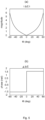
- Procédé pour déterminer une relation de phase électrique entre des éléments d'antenne (160a, 160b) dans un réseau d'antennes (190a, 190b), le procédé étant exécuté par un dispositif émetteur-récepteur radio (200), le procédé comprenant :l'obtention (S102) de mesures du signal radio tel qu'il est reçu dans deux faisceaux de réception (140a, 140b) couvrant un secteur angulaire donné (150) ayant une largeur, dans lequel les faisceaux de réception (140a, 140b) ont des motifs de faisceaux complexes différents, et dans lequel les motifs de faisceaux complexes sont générés pour être adaptables à la largeur du secteur angulaire (150) dans lequel le signal radio doit être reçu ;l'estimation (S104) de l'angle d'arrivée (α) du signal radio pour au moins un port de polarisation de chacun des faisceaux de réception (140a, 140b) à l'aide des mesures dans les deux faisceaux de réception (140a, 140b) ; etla détermination (S106), à partir de l'angle d'arrivée (α) estimé pour chaque port de polarisation, d'une relation de phase électrique entre des éléments d'antenne (160a, 160b) dans le réseau d'antennes (190a, 190b) qui correspond à l'angle d'arrivée estimé (α), dans lequel chaque faisceau de réception (140a, 140b) a deux ports de polarisation, et dans lequel les deux ports de polarisation de chaque faisceau de réception (140a, 140b) ont des polarisations mutuellement différentes, et dans lequel l'angle d'arrivée (α) du signal radio dans chacun des deux ports de polarisation représente une valeur intermédiaire, et dans lequel l'angle d'arrivée (α) est estimé à l'aide d'une combinaison des valeurs intermédiaires.
- Procédé selon la revendication 1, dans lequel l'angle d'arrivée (α) du signal radio pour chaque port de polarisation est estimé indépendamment de l'angle d'arrivée (α) d'autres ports de polarisation.
- Procédé selon la revendication 1, dans lequel les deux faisceaux de réception (140a, 140b) sont générés de sorte qu'à n'importe quel angle dans le secteur angulaire donné (150) au plus l'un des faisceaux de réception (140a, 140b) a un gain de puissance en dessous d'un seuil lorsqu'il est additionné sur les deux ports de polarisation de chaque faisceau de réception (140a, 140b).
- Procédé selon la revendication 3, dans lequel les motifs de faisceaux complexes sont pondérés et additionnés sur les deux ports de polarisation lors de l'estimation de l'angle d'arrivée (α) du signal radio.
- Procédé selon la revendication 1, dans lequel les faisceaux de réception (140a, 140b) sont générés à l'aide d'une formation de faisceau à double polarisation.
- Procédé selon la revendication 5, dans lequel la formation de faisceau à double polarisation dans le réseau d'antennes (190a, 190b) est basée sur une première matrice de pondération ayant un premier vecteur de pondération non nul pour une première des deux polarisations et une seconde matrice de pondération ayant un second vecteur de pondération non nul pour une seconde des deux polarisations,dans lequel la seconde matrice de pondération est basée sur les vecteurs de pondération de la première matrice de pondération, dans lequel la première matrice de pondération est appliquée auxdits éléments d'antenne (160a, 160b) pour générer un premier des deux faisceaux de réception (140a, 140b) pour un premier des deux ports de polarisation, etdans lequel la seconde matrice de pondération est appliquée auxdits éléments d'antenne (160a, 160b) pour générer ledit premier des deux faisceaux de réception (140a, 140b) pour un second des deux ports de polarisation.
- Procédé selon la revendication 5, dans lequel la formation de faisceau à double polarisation dans le réseau d'antennes (190a, 190b) est basée sur la génération d'un ou deux ports de faisceau, dans lequel le ou les deux ports de faisceau sont définis en combinant au moins deux réseaux virtuels sans chevauchement des éléments d'antenne (160a, 160b), dans lequel les réseaux virtuels des deux faisceaux de réception (140a, 140b) sont associés à des vecteurs de pondération mutuellement différents, dans lequel un vecteur de pondération appliqué à un réseau virtuel définit un port de réseau virtuel,dans lequel chaque réseau virtuel a deux ports de réseau virtuel, les deux ports de réseau virtuel ayant des motifs de puissance identiques et une polarisation mutuellement orthogonale, dans lequel les au moins deux réseaux virtuels sans chevauchement sont combinés via des pondérations d'extension,dans lequel les pondérations d'extension mappent chacun des deux faisceaux de réception (140a, 140b) aux ports de réseau virtuel de sorte que chaque faisceau de réception, lorsqu'il est additionné sur les deux ports de polarisation, a un motif de puissance identique au réseau virtuel lorsqu'il est additionné sur les deux ports de réseau virtuel, etdans lequel au moins certaines des pondérations d'expansion ont une amplitude identique non nulle et sont liées en phase pour former les deux faisceaux de réception (140a, 140b).
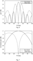
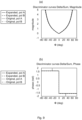
- Procédé selon la revendication 1, dans lequel l'estimation de l'angle d'arrivée (α) du signal radio comprend la comparaison d'une amplitude complexe des mesures pour chacun des ports de polarisation dans les deux faisceaux de réception (140a, 140b) à une fonction de discriminateur.
- Procédé selon la revendication 8, dans lequel la fonction de discriminateur est basée sur les motifs de faisceaux complexes et est, dans le secteur angulaire donné (150), une fonction biunivoque de l'angle d'arrivée (α).
- Procédé selon les revendications 8 et 9, dans lequel la fonction de discriminateur telle qu'appliquée à chacun des deux faisceaux de réception (140a, 140b) est identique à la fonction de discriminateur telle qu'appliquée aux ports du réseau virtuel correspondant aux deux faisceaux de réception (140a, 140b).
- Procédé selon la revendication 1, dans lequel le signal est reçu d'un autre dispositif émetteur-récepteur radio (300), le procédé comprenant en outre :
la communication (S108) avec ledit autre dispositif émetteur-récepteur radio (300) dans un faisceau pointant dans une direction sélectionnée selon la relation de phase électrique. - Procédé selon l'une quelconque des revendications 1 à 12, dans lequel chaque mesure du signal radio correspond soit à une totalité soit à une moitié de symbole de multiplexage orthogonal par répartition en fréquence, OFDM, telle qu'une totalité ou une moitié de symbole OFDM sur lequel l'une respective des mesures est basée sur la réception dans chacun des deux faisceaux de réception (140a, 140b).
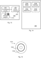
- Dispositif émetteur-récepteur radio (200) pour déterminer une relation de phase électrique entre des éléments d'antenne (160a, 160b) dans un réseau d'antennes (190a, 190b), le dispositif émetteur-récepteur radio (200) comprenant un circuit de traitement (210), le circuit de traitement étant configuré pour amener le dispositif émetteur-récepteur radio (200) à :obtenir des mesures du signal radio tel qu'il est reçu dans deux faisceaux de réception (140a, 140b) couvrant un secteur angulaire donné (150) ayant une largeur, dans lequel les faisceaux de réception (140a, 140b) ont des motifs de faisceaux complexes différents, et dans lequel les motifs de faisceaux complexes sont générés pour être adaptables à la largeur du secteur angulaire (150) dans lequel le signal radio doit être reçu ;estimer l'angle d'arrivée (α) du signal radio pour au moins un port de polarisation de chacun des faisceaux de réception (140a, 140b) à l'aide des mesures dans les deux faisceaux de réception (140a, 140b) ; etdéterminer, à partir de l'angle d'arrivée (α) estimé pour chaque port de polarisation, une relation de phase électrique entre des éléments d'antenne (160a, 160b) dans le réseau d'antennes (190a, 190b) qui correspond à l'angle d'arrivée estimé (α), dans lequel chaque faisceau de réception (140a, 140b) a deux ports de polarisation, et dans lequel les deux ports de polarisation de chaque faisceau de réception (140a, 140b) ont des polarisations mutuellement différentes, et dans lequel l'angle d'arrivée (α) du signal radio dans chacun des deux ports de polarisation représente une valeur intermédiaire, et dans lequel l'angle d'arrivée (α) est estimé à l'aide d'une combinaison des valeurs intermédiaires.
- Programme informatique (1520) pour déterminer une relation de phase électrique entre des éléments d'antenne (160a, 160b) dans un réseau d'antennes (190a, 190b), le programme informatique comprenant un code informatique qui, lorsqu'il est exécuté sur un circuit de traitement (210) d'un dispositif émetteur-récepteur radio (200), amène le dispositif émetteur-récepteur radio (200) à :obtenir (S102) des mesures du signal radio tel qu'il est reçu dans deux faisceaux de réception (140a, 140b) couvrant un secteur angulaire donné (150) ayant une largeur, dans lequel les faisceaux de réception (140a, 140b) ont des motifs de faisceaux complexes différents, et dans lequel les motifs de faisceaux complexes sont générés pour être adaptables à la largeur du secteur angulaire (150) à l'intérieur duquel le signal radio doit être reçu ;estimer (S104) l'angle d'arrivée (α) du signal radio pour au moins un port de polarisation de chacun des faisceaux de réception (140a, 140b) à l'aide des mesures dans les deux faisceaux de réception (140a, 140b) ; etdéterminer (SI06), à partir de l'angle d'arrivée (α) estimé pour chaque port de polarisation, une relation de phase électrique entre des éléments d'antenne (160a, 160b) dans le réseau d'antennes (190a, 190b) qui correspond à l'angle d'arrivée estimé (α), dans lequel chaque faisceau de réception (140a, 140b) a deux ports de polarisation, et dans lequel les deux ports de polarisation de chaque faisceau de réception (140a, 140b) ont des polarisations mutuellement différentes, et dans lequel l'angle d'arrivée (α) du signal radio dans chacun des deux ports de polarisation représente une valeur intermédiaire, et dans lequel l'angle d'arrivée (α) est estimé à l'aide d'une combinaison des valeurs intermédiaires.
- Produit de programme informatique (1510) comprenant un programme informatique (1520) selon la revendication 14, et un support de stockage lisible par ordinateur (1530) sur lequel le programme informatique est stocké.
Applications Claiming Priority (1)
| Application Number | Priority Date | Filing Date | Title |
|---|---|---|---|
| PCT/EP2017/063459 WO2018219472A1 (fr) | 2017-06-02 | 2017-06-02 | Détermination d'une relation de phase électrique dans un réseau de communications |
Publications (3)
| Publication Number | Publication Date |
|---|---|
| EP3632000A1 EP3632000A1 (fr) | 2020-04-08 |
| EP3632000C0 EP3632000C0 (fr) | 2023-08-16 |
| EP3632000B1 true EP3632000B1 (fr) | 2023-08-16 |
Family
ID=59009690
Family Applications (1)
| Application Number | Title | Priority Date | Filing Date |
|---|---|---|---|
| EP17727875.1A Active EP3632000B1 (fr) | 2017-06-02 | 2017-06-02 | Détermination d'une relation de phase électrique dans un réseau de communications |
Country Status (4)
| Country | Link |
|---|---|
| US (1) | US11411310B2 (fr) |
| EP (1) | EP3632000B1 (fr) |
| CN (1) | CN110663198B (fr) |
| WO (1) | WO2018219472A1 (fr) |
Families Citing this family (2)
| Publication number | Priority date | Publication date | Assignee | Title |
|---|---|---|---|---|
| EP3571782B1 (fr) * | 2017-12-20 | 2021-03-03 | Huawei Technologies Co. Ltd. | Dispositifs, procédés et programmes informatiques pour une communication sans fil avec gestion de faisceau rotatif |
| US10673587B2 (en) * | 2018-02-27 | 2020-06-02 | Telefonaktiebolaget Lm Ericsson (Publ) | Beam management for a radio transceiver device |
Family Cites Families (53)
| Publication number | Priority date | Publication date | Assignee | Title |
|---|---|---|---|---|
| US3176297A (en) | 1962-11-08 | 1965-03-30 | Sperry Rand Corp | Antenna systems |
| GB1270806A (en) * | 1968-05-31 | 1972-04-19 | Emi Ltd | Improvements relating to aerial arrangements |
| US3824595A (en) | 1971-06-04 | 1974-07-16 | Bunker Ramo | High accuracy direction finding system |
| US4170774A (en) | 1972-01-24 | 1979-10-09 | United Technologies Corporation | Amplitude selected phase interferometer angle measuring radar |
| US3860929A (en) | 1973-05-07 | 1975-01-14 | Texas Instruments Inc | Conformal array antenna/receiver processor system |
| US3969726A (en) * | 1975-02-27 | 1976-07-13 | Texas Instruments Incorporated | Two channel monopulse receiver |
| DE2929254C2 (de) | 1979-07-19 | 1982-05-06 | Siemens AG, 1000 Berlin und 8000 München | Antennensystem zur Peilung einer Mikrowellen-Signalquelle |
| FI85427C (fi) | 1989-06-14 | 1992-04-10 | Vaisala Oy | Foerfarande och anordning foer ett objekts azimut- och elevationsmaetning. |
| DE69431582T2 (de) | 1993-08-12 | 2003-03-06 | Nortel Networks Ltd | Antenneneinrichtung für Basisstation |
| US5541608A (en) | 1995-03-29 | 1996-07-30 | Itt Corporation | Hybrid amplitude/phase comparison direction finding system |
| US5786791A (en) * | 1997-02-24 | 1998-07-28 | Motorola, Inc. | Method for determining an angle of arrival of a signal transmitted by a remote unit in a communication system |
| US6061022A (en) | 1999-06-04 | 2000-05-09 | Itt Manufacturing Enterprises, Inc. | Azimuth and elevation direction finding system based on hybrid amplitude/phase comparison |
| JP2004503159A (ja) | 2000-07-10 | 2004-01-29 | アンドリュー・コーポレイション | セル式アンテナ |
| JP2002151937A (ja) | 2000-11-15 | 2002-05-24 | Nec Corp | 適応アレーアンテナ受信装置 |
| JP3923897B2 (ja) | 2000-12-23 | 2007-06-06 | ノキア コーポレイション | 到来方向を推定するための基地局、基地局モジュールおよび方法 |
| US6812889B2 (en) | 2002-01-24 | 2004-11-02 | Motorola, Inc. | Methods and apparatus for determining a direction of arrival in a wireless communication system |
| US7042394B2 (en) | 2002-08-14 | 2006-05-09 | Skipper Wireless Inc. | Method and system for determining direction of transmission using multi-facet antenna |
| DE60313336T2 (de) | 2002-08-21 | 2008-04-10 | Zyray Wireless, Inc., San Diego | Antennengruppe mit virtuellen antennenelementen und zugehörige methode |
| US6950064B2 (en) | 2002-12-16 | 2005-09-27 | Next-Rf, Inc. | System and method for ascertaining angle of arrival of an electromagnetic signal |
| GB0316402D0 (en) | 2003-07-12 | 2003-08-13 | Qinetiq Ltd | Direction finding |
| US7313403B2 (en) | 2003-08-06 | 2007-12-25 | Hong Kong Applied Science And Technology Research Institute Co., Ltd. | Location positioning in wireless networks |
| US7453946B2 (en) | 2003-09-03 | 2008-11-18 | Intel Corporation | Communication system and method for channel estimation and beamforming using a multi-element array antenna |
| KR100770875B1 (ko) * | 2004-05-24 | 2007-10-26 | 삼성전자주식회사 | 배열 안테나 시스템에서 간섭전력 추정을 이용한 빔 형성장치 및 방법 |
| US6992622B1 (en) * | 2004-10-15 | 2006-01-31 | Interdigital Technology Corporation | Wireless communication method and antenna system for determining direction of arrival information to form a three-dimensional beam used by a transceiver |
| US7242350B1 (en) | 2004-10-20 | 2007-07-10 | Raytheon Company | Estimating an angle-of-arrival of a signal by determining polarization |
| US7342535B2 (en) * | 2005-04-08 | 2008-03-11 | Samsung Electronics Co., Ltd. | Beam-forming apparatus and method using a spatial interpolation based on regular spatial sampling |
| CA2542445A1 (fr) * | 2006-04-07 | 2007-10-07 | Tenxc Wireless Inc. | Systeme adaptatif multifaisceau |
| US8305265B2 (en) * | 2007-05-29 | 2012-11-06 | Toyon Research Corporation | Radio-based direction-finding navigation system using small antenna |
| US20080303714A1 (en) * | 2007-05-29 | 2008-12-11 | Ezal Kenan O | Compact single-aperture antenna and navigation system |
| US8254487B2 (en) | 2007-08-09 | 2012-08-28 | Samsung Electronics Co., Ltd. | Method and apparatus of codebook-based single-user closed-loop transmit beamforming (SU-CLTB) for OFDM wireless systems |
| FR2938345B1 (fr) | 2008-11-07 | 2010-12-31 | Thales Sa | Procede de determination de la direction d'arrivee d'une onde electromagnetique |
| WO2010139840A1 (fr) * | 2009-06-03 | 2010-12-09 | Elektrobit System Test Oy | Essai en liaison radio |
| GB2471669B (en) * | 2009-07-06 | 2012-04-04 | Socowave Technologies Ltd | Wireless network element and method for antenna array control |
| US9545222B2 (en) * | 2009-09-01 | 2017-01-17 | Adidas Ag | Garment with noninvasive method and system for monitoring physiological characteristics and athletic performance |
| US8994588B2 (en) * | 2009-10-28 | 2015-03-31 | Telefonaktiebolaget L M Ericsson (Publ) | Method of designing weight vectors for a dual beam antenna with orthogonal polarizations |
| US8558735B2 (en) * | 2010-08-20 | 2013-10-15 | Lockheed Martin Corporation | High-resolution radar map for multi-function phased array radar |
| US20130286960A1 (en) | 2012-04-30 | 2013-10-31 | Samsung Electronics Co., Ltd | Apparatus and method for control channel beam management in a wireless system with a large number of antennas |
| US9924381B2 (en) * | 2012-08-13 | 2018-03-20 | Telefonaktiebolaget Lm Ericsson (Publ) | Enhancing uplink measurements for positioning by adaptively using multi-antenna systems |
| TWI457585B (zh) | 2012-12-11 | 2014-10-21 | Univ Nat Chiao Tung | 角度偵測方法及其裝置 |
| CN104010361B (zh) | 2013-02-22 | 2018-04-10 | 中兴通讯股份有限公司 | 定位系统和方法 |
| US10794984B2 (en) * | 2013-05-22 | 2020-10-06 | New York University | System, method and computer-readable medium for estimating direction of arrival of a signal incident on at least one antenna array |
| US9680234B2 (en) * | 2013-08-28 | 2017-06-13 | Harris Corporation | Dual polarization ground-based phased array antenna system for aircraft communications and associated methods |
| EP3140921B1 (fr) * | 2014-05-08 | 2019-12-25 | Telefonaktiebolaget LM Ericsson (publ) | Formation de faisceaux à l'aide d'un agencement d'antennes |
| US9819081B2 (en) * | 2014-07-07 | 2017-11-14 | Qatar Foundation For Education, Science And Comminity Development | Reconfigurable radio direction finder system and method |
| KR102207844B1 (ko) * | 2014-07-08 | 2021-01-26 | 한국전자통신연구원 | 적어도 하나의 안테나 배열에 입사하는 신호의 도착 방향을 추정하는 시스템, 방법, 그리고 컴퓨터 판독가능 매체 |
| US9398468B1 (en) * | 2014-12-29 | 2016-07-19 | Huawei Technologies Co., Ltd. | Cellular array with steerable spotlight beams |
| JP6457108B2 (ja) | 2015-03-06 | 2019-01-23 | テレフオンアクチーボラゲット エルエム エリクソン(パブル) | アンテナ装置を使用するビーム形成 |
| US20160268681A1 (en) * | 2015-03-10 | 2016-09-15 | Board Of Trustees Of Michigan State University | Three-Element Antenna Array for Wireless Handsets |
| CN107210802A (zh) | 2015-05-20 | 2017-09-26 | 联发科技股份有限公司 | 有效波束训练方法及通信装置和利用上述的网络控制装置 |
| US10705176B2 (en) | 2015-10-13 | 2020-07-07 | Northrop Grumman Systems Corporation | Signal direction processing for an antenna array |
| US10554279B2 (en) * | 2016-02-25 | 2020-02-04 | Apple Inc. | Device and method for synchronous beam switching |
| US20180038934A1 (en) | 2016-08-03 | 2018-02-08 | Sr Technologies, Inc. | Discrimination of signal angle of arrival using at least two antennas |
| US11139873B2 (en) * | 2017-05-24 | 2021-10-05 | Telefonaktiebolaget Lm Ericsson (Publ) | Beam width adjustment |
-
2017
- 2017-06-02 CN CN201780091518.2A patent/CN110663198B/zh active Active
- 2017-06-02 US US15/540,640 patent/US11411310B2/en active Active
- 2017-06-02 EP EP17727875.1A patent/EP3632000B1/fr active Active
- 2017-06-02 WO PCT/EP2017/063459 patent/WO2018219472A1/fr active Application Filing
Also Published As
| Publication number | Publication date |
|---|---|
| EP3632000A1 (fr) | 2020-04-08 |
| EP3632000C0 (fr) | 2023-08-16 |
| CN110663198B (zh) | 2024-03-08 |
| US20180358695A1 (en) | 2018-12-13 |
| US11411310B2 (en) | 2022-08-09 |
| CN110663198A (zh) | 2020-01-07 |
| WO2018219472A1 (fr) | 2018-12-06 |
Similar Documents
| Publication | Publication Date | Title |
|---|---|---|
| US11444707B2 (en) | Angle of arrival estimation in a radio communications network | |
| CN106464332B (zh) | 使用天线布置的波束形成 | |
| US11550017B2 (en) | Angle of arrival estimation in a radio communications network | |
| EP3381133B1 (fr) | Configuration de système d'antenne | |
| US10382110B2 (en) | Adaptive user-specific beam forming | |
| EP3732796B1 (fr) | Gestion de faisceau d'un dispositif émetteur-récepteur radio | |
| US11271696B2 (en) | Beam management of a radio transceiver device | |
| EP3632000B1 (fr) | Détermination d'une relation de phase électrique dans un réseau de communications | |
| CN111316571A (zh) | 高效波束搜索 | |
| EP3433943B1 (fr) | Noeud de communication sans fil conçu pour émettre des faisceaux d'antenne de différents types | |
| WO2019068305A1 (fr) | Dispositif de réception et procédés associés | |
| EP3360265B1 (fr) | Estimation de condition de canal | |
| WO2024092710A1 (fr) | Nœud de réseau et procédé permettant d'estimer une erreur d'étalonnage d'antenne | |
| WO2019001692A1 (fr) | Détermination de vecteurs de pondération complexes destinés à un dispositif émetteur-récepteur radio | |
| WO2021043399A1 (fr) | Transmission formée en faisceau vers un dispositif émetteur-récepteur radio | |
| EP4302417A1 (fr) | Transmission de ressources de signal de référence |
Legal Events
| Date | Code | Title | Description |
|---|---|---|---|
| STAA | Information on the status of an ep patent application or granted ep patent |
Free format text: STATUS: UNKNOWN |
|
| STAA | Information on the status of an ep patent application or granted ep patent |
Free format text: STATUS: THE INTERNATIONAL PUBLICATION HAS BEEN MADE |
|
| PUAI | Public reference made under article 153(3) epc to a published international application that has entered the european phase |
Free format text: ORIGINAL CODE: 0009012 |
|
| STAA | Information on the status of an ep patent application or granted ep patent |
Free format text: STATUS: REQUEST FOR EXAMINATION WAS MADE |
|
| 17P | Request for examination filed |
Effective date: 20191216 |
|
| AK | Designated contracting states |
Kind code of ref document: A1 Designated state(s): AL AT BE BG CH CY CZ DE DK EE ES FI FR GB GR HR HU IE IS IT LI LT LU LV MC MK MT NL NO PL PT RO RS SE SI SK SM TR |
|
| AX | Request for extension of the european patent |
Extension state: BA ME |
|
| DAV | Request for validation of the european patent (deleted) | ||
| DAX | Request for extension of the european patent (deleted) | ||
| STAA | Information on the status of an ep patent application or granted ep patent |
Free format text: STATUS: EXAMINATION IS IN PROGRESS |
|
| STAA | Information on the status of an ep patent application or granted ep patent |
Free format text: STATUS: EXAMINATION IS IN PROGRESS |
|
| 17Q | First examination report despatched |
Effective date: 20200922 |
|
| STAA | Information on the status of an ep patent application or granted ep patent |
Free format text: STATUS: EXAMINATION IS IN PROGRESS |
|
| GRAP | Despatch of communication of intention to grant a patent |
Free format text: ORIGINAL CODE: EPIDOSNIGR1 |
|
| STAA | Information on the status of an ep patent application or granted ep patent |
Free format text: STATUS: GRANT OF PATENT IS INTENDED |
|
| INTG | Intention to grant announced |
Effective date: 20230323 |
|
| GRAS | Grant fee paid |
Free format text: ORIGINAL CODE: EPIDOSNIGR3 |
|
| GRAA | (expected) grant |
Free format text: ORIGINAL CODE: 0009210 |
|
| STAA | Information on the status of an ep patent application or granted ep patent |
Free format text: STATUS: THE PATENT HAS BEEN GRANTED |
|
| AK | Designated contracting states |
Kind code of ref document: B1 Designated state(s): AL AT BE BG CH CY CZ DE DK EE ES FI FR GB GR HR HU IE IS IT LI LT LU LV MC MK MT NL NO PL PT RO RS SE SI SK SM TR |
|
| REG | Reference to a national code |
Ref country code: GB Ref legal event code: FG4D |
|
| REG | Reference to a national code |
Ref country code: CH Ref legal event code: EP |
|
| REG | Reference to a national code |
Ref country code: DE Ref legal event code: R096 Ref document number: 602017072766 Country of ref document: DE |
|
| GRAT | Correction requested after decision to grant or after decision to maintain patent in amended form |
Free format text: ORIGINAL CODE: EPIDOSNCDEC |
|
| REG | Reference to a national code |
Ref country code: IE Ref legal event code: FG4D |
|
| U01 | Request for unitary effect filed |
Effective date: 20230831 |
|
| RAP4 | Party data changed (patent owner data changed or rights of a patent transferred) |
Owner name: TELEFONAKTIEBOLAGET LM ERICSSON (PUBL) |
|
| U07 | Unitary effect registered |
Designated state(s): AT BE BG DE DK EE FI FR IT LT LU LV MT NL PT SE SI Effective date: 20230912 |
|
| PG25 | Lapsed in a contracting state [announced via postgrant information from national office to epo] |
Ref country code: GR Free format text: LAPSE BECAUSE OF FAILURE TO SUBMIT A TRANSLATION OF THE DESCRIPTION OR TO PAY THE FEE WITHIN THE PRESCRIBED TIME-LIMIT Effective date: 20231117 |
|
| PG25 | Lapsed in a contracting state [announced via postgrant information from national office to epo] |
Ref country code: IS Free format text: LAPSE BECAUSE OF FAILURE TO SUBMIT A TRANSLATION OF THE DESCRIPTION OR TO PAY THE FEE WITHIN THE PRESCRIBED TIME-LIMIT Effective date: 20231216 |
|
| PG25 | Lapsed in a contracting state [announced via postgrant information from national office to epo] |
Ref country code: RS Free format text: LAPSE BECAUSE OF FAILURE TO SUBMIT A TRANSLATION OF THE DESCRIPTION OR TO PAY THE FEE WITHIN THE PRESCRIBED TIME-LIMIT Effective date: 20230816 Ref country code: NO Free format text: LAPSE BECAUSE OF FAILURE TO SUBMIT A TRANSLATION OF THE DESCRIPTION OR TO PAY THE FEE WITHIN THE PRESCRIBED TIME-LIMIT Effective date: 20231116 Ref country code: IS Free format text: LAPSE BECAUSE OF FAILURE TO SUBMIT A TRANSLATION OF THE DESCRIPTION OR TO PAY THE FEE WITHIN THE PRESCRIBED TIME-LIMIT Effective date: 20231216 Ref country code: HR Free format text: LAPSE BECAUSE OF FAILURE TO SUBMIT A TRANSLATION OF THE DESCRIPTION OR TO PAY THE FEE WITHIN THE PRESCRIBED TIME-LIMIT Effective date: 20230816 Ref country code: GR Free format text: LAPSE BECAUSE OF FAILURE TO SUBMIT A TRANSLATION OF THE DESCRIPTION OR TO PAY THE FEE WITHIN THE PRESCRIBED TIME-LIMIT Effective date: 20231117 |
|
| PG25 | Lapsed in a contracting state [announced via postgrant information from national office to epo] |
Ref country code: PL Free format text: LAPSE BECAUSE OF FAILURE TO SUBMIT A TRANSLATION OF THE DESCRIPTION OR TO PAY THE FEE WITHIN THE PRESCRIBED TIME-LIMIT Effective date: 20230816 |
|
| PG25 | Lapsed in a contracting state [announced via postgrant information from national office to epo] |
Ref country code: ES Free format text: LAPSE BECAUSE OF FAILURE TO SUBMIT A TRANSLATION OF THE DESCRIPTION OR TO PAY THE FEE WITHIN THE PRESCRIBED TIME-LIMIT Effective date: 20230816 |
|
| PG25 | Lapsed in a contracting state [announced via postgrant information from national office to epo] |
Ref country code: SM Free format text: LAPSE BECAUSE OF FAILURE TO SUBMIT A TRANSLATION OF THE DESCRIPTION OR TO PAY THE FEE WITHIN THE PRESCRIBED TIME-LIMIT Effective date: 20230816 Ref country code: RO Free format text: LAPSE BECAUSE OF FAILURE TO SUBMIT A TRANSLATION OF THE DESCRIPTION OR TO PAY THE FEE WITHIN THE PRESCRIBED TIME-LIMIT Effective date: 20230816 Ref country code: ES Free format text: LAPSE BECAUSE OF FAILURE TO SUBMIT A TRANSLATION OF THE DESCRIPTION OR TO PAY THE FEE WITHIN THE PRESCRIBED TIME-LIMIT Effective date: 20230816 Ref country code: CZ Free format text: LAPSE BECAUSE OF FAILURE TO SUBMIT A TRANSLATION OF THE DESCRIPTION OR TO PAY THE FEE WITHIN THE PRESCRIBED TIME-LIMIT Effective date: 20230816 Ref country code: SK Free format text: LAPSE BECAUSE OF FAILURE TO SUBMIT A TRANSLATION OF THE DESCRIPTION OR TO PAY THE FEE WITHIN THE PRESCRIBED TIME-LIMIT Effective date: 20230816 |