EP3732796B1 - Gestion de faisceau d'un dispositif émetteur-récepteur radio - Google Patents
Gestion de faisceau d'un dispositif émetteur-récepteur radio Download PDFInfo
- Publication number
- EP3732796B1 EP3732796B1 EP18702634.9A EP18702634A EP3732796B1 EP 3732796 B1 EP3732796 B1 EP 3732796B1 EP 18702634 A EP18702634 A EP 18702634A EP 3732796 B1 EP3732796 B1 EP 3732796B1
- Authority
- EP
- European Patent Office
- Prior art keywords
- radio transceiver
- frequency
- transceiver device
- reference signal
- polarization
- Prior art date
- Legal status (The legal status is an assumption and is not a legal conclusion. Google has not performed a legal analysis and makes no representation as to the accuracy of the status listed.)
- Active
Links
- 230000010287 polarization Effects 0.000 claims description 102
- 238000000034 method Methods 0.000 claims description 46
- 230000005540 biological transmission Effects 0.000 claims description 31
- 230000001419 dependent effect Effects 0.000 claims description 28
- 238000004590 computer program Methods 0.000 claims description 27
- 238000012545 processing Methods 0.000 claims description 19
- 230000010363 phase shift Effects 0.000 claims description 7
- 238000004891 communication Methods 0.000 description 23
- 238000010586 diagram Methods 0.000 description 6
- 230000006870 function Effects 0.000 description 4
- 238000005259 measurement Methods 0.000 description 4
- 230000003287 optical effect Effects 0.000 description 3
- 238000003491 array Methods 0.000 description 2
- 230000008901 benefit Effects 0.000 description 2
- 230000008859 change Effects 0.000 description 2
- 230000007246 mechanism Effects 0.000 description 2
- 230000011664 signaling Effects 0.000 description 2
- 238000010897 surface acoustic wave method Methods 0.000 description 2
- 230000001960 triggered effect Effects 0.000 description 2
- 230000003213 activating effect Effects 0.000 description 1
- 230000002776 aggregation Effects 0.000 description 1
- 238000004220 aggregation Methods 0.000 description 1
- 230000009286 beneficial effect Effects 0.000 description 1
- 230000001427 coherent effect Effects 0.000 description 1
- 125000004122 cyclic group Chemical group 0.000 description 1
- 230000009977 dual effect Effects 0.000 description 1
- 238000013507 mapping Methods 0.000 description 1
- 238000010295 mobile communication Methods 0.000 description 1
- 230000002085 persistent effect Effects 0.000 description 1
- 230000004044 response Effects 0.000 description 1
- 239000007787 solid Substances 0.000 description 1
Images


Classifications
-
- H—ELECTRICITY
- H04—ELECTRIC COMMUNICATION TECHNIQUE
- H04B—TRANSMISSION
- H04B7/00—Radio transmission systems, i.e. using radiation field
- H04B7/02—Diversity systems; Multi-antenna system, i.e. transmission or reception using multiple antennas
- H04B7/04—Diversity systems; Multi-antenna system, i.e. transmission or reception using multiple antennas using two or more spaced independent antennas
- H04B7/06—Diversity systems; Multi-antenna system, i.e. transmission or reception using multiple antennas using two or more spaced independent antennas at the transmitting station
- H04B7/0686—Hybrid systems, i.e. switching and simultaneous transmission
- H04B7/0695—Hybrid systems, i.e. switching and simultaneous transmission using beam selection
-
- H—ELECTRICITY
- H04—ELECTRIC COMMUNICATION TECHNIQUE
- H04B—TRANSMISSION
- H04B7/00—Radio transmission systems, i.e. using radiation field
- H04B7/02—Diversity systems; Multi-antenna system, i.e. transmission or reception using multiple antennas
- H04B7/10—Polarisation diversity; Directional diversity
-
- H—ELECTRICITY
- H04—ELECTRIC COMMUNICATION TECHNIQUE
- H04L—TRANSMISSION OF DIGITAL INFORMATION, e.g. TELEGRAPHIC COMMUNICATION
- H04L5/00—Arrangements affording multiple use of the transmission path
- H04L5/0001—Arrangements for dividing the transmission path
- H04L5/0003—Two-dimensional division
- H04L5/0005—Time-frequency
-
- H—ELECTRICITY
- H04—ELECTRIC COMMUNICATION TECHNIQUE
- H04L—TRANSMISSION OF DIGITAL INFORMATION, e.g. TELEGRAPHIC COMMUNICATION
- H04L5/00—Arrangements affording multiple use of the transmission path
- H04L5/003—Arrangements for allocating sub-channels of the transmission path
- H04L5/0048—Allocation of pilot signals, i.e. of signals known to the receiver
-
- H—ELECTRICITY
- H04—ELECTRIC COMMUNICATION TECHNIQUE
- H04B—TRANSMISSION
- H04B7/00—Radio transmission systems, i.e. using radiation field
- H04B7/02—Diversity systems; Multi-antenna system, i.e. transmission or reception using multiple antennas
- H04B7/04—Diversity systems; Multi-antenna system, i.e. transmission or reception using multiple antennas using two or more spaced independent antennas
- H04B7/06—Diversity systems; Multi-antenna system, i.e. transmission or reception using multiple antennas using two or more spaced independent antennas at the transmitting station
- H04B7/0613—Diversity systems; Multi-antenna system, i.e. transmission or reception using multiple antennas using two or more spaced independent antennas at the transmitting station using simultaneous transmission
- H04B7/0615—Diversity systems; Multi-antenna system, i.e. transmission or reception using multiple antennas using two or more spaced independent antennas at the transmitting station using simultaneous transmission of weighted versions of same signal
- H04B7/0619—Diversity systems; Multi-antenna system, i.e. transmission or reception using multiple antennas using two or more spaced independent antennas at the transmitting station using simultaneous transmission of weighted versions of same signal using feedback from receiving side
- H04B7/0621—Feedback content
- H04B7/063—Parameters other than those covered in groups H04B7/0623 - H04B7/0634, e.g. channel matrix rank or transmit mode selection
-
- H—ELECTRICITY
- H04—ELECTRIC COMMUNICATION TECHNIQUE
- H04B—TRANSMISSION
- H04B7/00—Radio transmission systems, i.e. using radiation field
- H04B7/02—Diversity systems; Multi-antenna system, i.e. transmission or reception using multiple antennas
- H04B7/04—Diversity systems; Multi-antenna system, i.e. transmission or reception using multiple antennas using two or more spaced independent antennas
- H04B7/08—Diversity systems; Multi-antenna system, i.e. transmission or reception using multiple antennas using two or more spaced independent antennas at the receiving station
- H04B7/0891—Space-time diversity
- H04B7/0894—Space-time diversity using different delays between antennas
Definitions
- Embodiments presented herein relate to a method, a radio transceiver device, a computer program, and a computer program product for participating in beam management.
- communications networks there may be a challenge to obtain good performance and capacity for a given communications protocol, its parameters and the physical environment in which the communications network is deployed.
- frequency bands at many different carrier frequencies could be needed. For example, low such frequency bands could be needed to achieve sufficient network coverage for wireless devices and higher frequency bands (e.g. at millimeter wavelengths (mmW), i.e. near and above 30 GHz) could be needed to reach required network capacity.
- mmW millimeter wavelengths
- the propagation properties of the radio channel are more challenging and beamforming both at the network node of the network and at the wireless devices might be required to reach a sufficient link budget.
- Narrow beam transmission and reception schemes might be needed at such high frequencies to compensate the expected high propagation loss.
- a respective beam can be applied at both the network-end (as represented by a network node or its transmission and reception point, TRP) and at the terminal-end (as represented by a terminal device), which typically is referred to as a beam pair link (BPL).
- TRP network-end
- BPL beam pair link
- One task of the beam management procedure is to discover and maintain beam pair links.
- a BPL i.e. both the beam used by the network node and the beam used by the terminal device
- CSI-RS channel state information reference signals
- the reference signals for beam management can be transmitted periodically, semi-persistently or aperiodic (event triggered) and they can be either shared between multiple terminal devices or be device-specific.
- the network node transmits the reference signal in different transmission (TX) beams on which the terminal device performs measurements, such as reference signal received power (RSRP), and reports back the N best TX beams (where N can be configured by the network).
- TX transmission
- RSRP reference signal received power
- N can be configured by the network.
- N resource indicators such as CSI-RS resource indicators (CRIs)
- the transmission of the reference signal on a given TX beam can be repeated to allow the terminal device to evaluate a suitable reception (RX) beam.
- the CSI-RS resources used for beam management might consist either of one or two CSI-RS ports.
- One benefit with using two-port CSI-RS resources is that one CSI-RS port can be transmitted per polarization, which means that the terminal device can measure average RSRP over two orthogonal polarizations and hence reduce the risk of polarization mismatch.
- One reason for using single port CSI-RS resources for beam management is for example that CSI-RS for so-called layer three (L3) mobility is currently only agreed for one-port CSI-RS and overhead can be reduced if these CSI-RS are reused also for beam management purposes.
- synchronization signal (SS) blocks that are transmitted periodically has been agreed to be used for beam management, and SS blocks only consist of one port.
- the incoming signals can arrive from all different directions.
- antenna arrays with single polarized antenna elements and an analog distribution network
- antenna arrays with dual-polarized elements might preferred such that dual-polarized beamforming can be used to generate beams with any beamwidth, ranging from the beamwidth of a single antenna element to the beamwidth of the entire antenna array.
- US 2017/338874 A1 is related to a multi-port transmitter that can synthesize and send a first plurality of transmit signals having a separability characteristic which permits them to be differentiated from one another.
- a receiver can then detect one or more receiver signals which include one or more combinations of received versions of the first plurality of transmit signals.
- the receiver may use the separability characteristic to determine the received versions of the first plurality of transmit signals from the one or more receiver signals.
- the receiver may determine an estimated signal corresponding to the estimated receiver response to a second plurality of virtual transmit signals which comprise a combination of the first plurality of transmit signals. Determining the estimated signal may include forming a combination of the received versions of the first plurality of transmit signals.
- US 2006/035605 A1 is related to a method and apparatus for reducing antenna correlation between multiple antennas.
- a transmitter generates at least two beams with a plurality of antennas.
- the generated beams are spatially separated to point away each other. Therefore, the transmitted signals travel through different channel conditions and arrive at a receiver mutually uncorrelated.
- the beams may be generated by antennas having different antenna pattern, or by an array antenna.
- the beams may be polarized differently.
- the schemes may be implemented on a subcarrier basis in an orthogonal frequency division multiplexing (OFDM) system. Trellis coded mapping may be utilized for adjacent symbols to be mapped to antennas with low correlation.
- OFDM orthogonal frequency division multiplexing
- US 2008/232502 A1 is related to a method for determining the appropriate combination of at least two MIMO transmission techniques for a radio link in between a transmitter and a receiver.
- the MIMO transmission techniques use at least two antennas with at least two polarizations.
- the appropriate combination is the combination of beamforming and at least one of polarization time coding, closed loop coherent combination of polarization beams and polarization multiplexing.
- the appropriate combination is chosen dependent on at least one of radio conditions of the radio link and relative velocity in between the transmitter and the receiver.
- the invention further relates to a method for receiving a transmission of a radio link in between a transmitter and a receiver.
- the invention also relates to a base station comprising a transmitter, a mobile terminal comprising a receiver and a communication network.
- An object of embodiments herein is to provide efficient beam management where the above noted issues are resolved, or at least mitigated.
- a method for participating in beam management is performed by a radio transceiver device.
- the method comprises receiving a reference signal from another radio transceiver device as part of participating in the beam management.
- the reference signal occupies time/frequency resources that extend over a first frequency interval.
- the reference signal is received in a reception beam.
- the reception beam has a frequency-dependent polarization over the first frequency interval.
- a radio transceiver device for participating in beam management.
- the radio transceiver device comprises processing circuitry.
- the processing circuitry is configured to cause the radio transceiver device to receive a reference signal from another radio transceiver device as part of participating in the beam management.
- the reference signal occupies time/frequency resources that extend over a first frequency interval.
- the reference signal is received in a reception beam.
- the reception beam has a frequency-dependent polarization over the first frequency interval.
- a radio transceiver device for participating in beam management.
- the radio transceiver device comprises a receive module configured to receive a reference signal from another radio transceiver device as part of participating in the beam management.
- the reference signal occupies time/frequency resources that extend over a first frequency interval.
- the reference signal is received in a reception beam.
- the reception beam has a frequency-dependent polarization over the first frequency interval.
- a computer program for participating in beam management comprising computer program code which, when run on a radio transceiver device, causes the radio transceiver device to perform a method according to the first aspect.
- a computer program product comprising a computer program according to the fourth aspect and a computer readable storage medium on which the computer program is stored.
- the computer readable storage medium could be a non-transitory computer readable storage medium.
- this enables polarization diversity to be attained during reception of reference signals used for beam management.
- this will increase the chance of the radio transceiver device selecting the true best transmission beam.
- this enables a preferred polarization setting for the radio transceiver device to be attained.
- this will increase the performance (such as resulting in higher throughput and/or higher signal to noise ratio) of coming data communications.
- Fig. 1 is a schematic diagram illustrating a communications network 100 where embodiments presented herein can be applied.
- the communications network 100 could be a third generation (3G) telecommunications network, a fourth generation (4G) telecommunications network, or a fifth (5G) telecommunications network and support any 3GPP telecommunications standard, where applicable.
- the communications network 100 comprises a radio transceiver device 200b configured to, via TRP 400b, provide network access to radio transceiver device 200a, comprising TRP 400a, in a radio access network 110.
- radio transceiver device 200a is part of, integrated with, or collocated with, a terminal device and radio transceiver device 200a is part of, integrated with, or collocated with, a network node.
- Radio access network 110 is operatively connected to a core network 120.
- the core network 120 is in turn operatively connected to a service network 130, such as the Internet.
- Radio transceiver device 200a is thereby, via the TRP 400b and radio transceiver device 200a, enabled to access services of, and exchange data with, the service network 130.
- Examples of network nodes are radio access network nodes, radio base stations, base transceiver stations, Node Bs, evolved Node Bs, g Node Bs, access points, access nodes, and backhaul nodes.
- Examples of terminal devices are wireless devices, mobile stations, mobile phones, handsets, wireless local loop phones, user equipment (UE), smartphones, laptop computers, tablet computers, network equipped sensors, network equipped vehicles, and so-called Internet of Things devices.
- radio transceiver device 200b in at least some of the herein disclosed embodiments is described as being a network node and radio transceiver device 200a is described as being a terminal device, the functionality of the herein disclosed radio transceiver device 200b could equally be implemented in a terminal device, and vice versa for radio transceiver device 200a.
- Radio transceiver device 200a is, via TRP 400a, configured to communicate with radio transceiver device 200b in beams 150, 150a, 150b. Further, radio transceiver device 200b is, via TRP 400b, configured to communicate with radio transceiver device 200a in beams 140, 140a, 140b. Radio transceiver device 200a, 200b could be configured to communicate using a variety of beams having different shapes and widths, herein generally referred to as having different beam patterns.
- a beam management procedure might be performed in order to find a BPL for radio transceiver device 200a and radio transceiver device 200b.
- the beam management procedure disclosed above might result in some issues.
- radio transceiver device 200a since the polarization state is wideband (i.e. the polarization is the same for the whole frequency interval) it will not be possible for radio transceiver device 200a to evaluate which polarization state that is preferred by only making measurements during reception of the reference signal in one single transmission beam.
- a radio transceiver device 200a a method performed by radio transceiver device 200a, a computer program product comprising code, for example in the form of a computer program, that when run on a radio transceiver device 200a, causes radio transceiver device 200a to perform the method.
- radio transceiver device 200a to attain polarization diversity over the frequency band during beam management procedure in order to attain polarization diversity for beam selection and/or a preferred polarization setting for coming data transmission/reception.
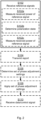
- Fig. 2 is a flowchart illustrating embodiments of methods for participating in beam management. The methods are performed by radio transceiver device 200a. The methods are advantageously provided as computer programs 820.
- radio transceiver device 200a is configured to perform step S102: S102: Radio transceiver device 200a receives a reference signal from another radio transceiver device 200b as part of participating in the beam management.
- the reference signal occupies time/frequency resources that extend over a first frequency interval.
- the reference signal is received in a reception beam 150, 150a, 150b.
- the reception beam 150, 150a, 150b has a frequency-dependent polarization over the first frequency interval.
- radio transceiver device 200a Due to that different polarizations, or polarization states, will be applied to different parts of the frequency band, it will be possible for radio transceiver device 200a to determine a preferred polarization state for coming data transmission/reception, by analyzing how the received power variates over frequency. In one embodiment radio transceiver device 200a thus additionally determines a preferred polarization state to be used during the coming data transmission/reception. This could be done by radio transceiver device 200a evaluating RSRP over the frequency band during the beam management procedure and find which parts of the frequency band that has the highest RSRP. Particularly, according to an embodiment radio transceiver device 200a is configured to perform (optional) steps S102a and S102b: S102a: Radio transceiver device 200a measures received power of the reference signal over the first frequency interval when receiving the reference signal.
- Radio transceiver device 200a determines at which frequency-dependent polarization in the first frequency interval the reference signal was received with highest received power.
- Steps S102a and S102b might be performed as part of step S102.
- Radio transceiver device 200a is able to determine which polarization state is used for which part of the frequency band since radio transceiver device 200 knows how much the polarization changes over the frequency interval). The preferred polarization state can then be applied for the whole frequency band during coming data transmission/reception by setting the appropriate phase of phase shifters.
- the beam management procedure involves radio transceiver device 200b to transmit the reference signal in two or more TX beams.
- at least two occurrence of the reference signal is received in the reception beam 150, 150a, 150b.
- Each occurrence corresponds to a different transmission beam 140, 140a, 140b in which the reference signal is transmitted from radio transceiver device 200b.
- radio transceiver device 200a is configured to perform (optional) step S102c:
- S102c Radio transceiver device 200a measures received power of each occurrence of the reference signal over the first frequency interval when receiving the reference signal.
- Step S102c might be performed as part of step S102.
- radio transceiver device 200a then reports back the N best transmission beams to radio transceiver device 200b, where N is configured by the network.
- radio transceiver device 200a is configured to perform (optional) step S104:
- the change of polarization over the frequency interval is caused by a time delay value, hereinafter denoted ⁇ . That is, according to the claimed invention the reception of the reference signal at the first antenna element set 430a and the second antenna element set 430b differ by a time delay value ⁇ .
- the time delay value ⁇ causes the frequency-dependent polarization over the first frequency interval.
- the time shift caused by the time delay value ⁇ will result in a frequency-dependent phase offset between the antenna elements of the two polarizations and thus the total polarization will change over frequency. That is, the time delay value ⁇ causes the frequency-dependent polarization to occur over the frequency interval.
- the time delay caused by the time delay value ⁇ is implemented in the time delay elements 440.
- Fig. 3 illustrates a TRP 400a of radio transceiver device 200a according to an embodiment.
- the TRP 400a of Fig. 3 comprises one single baseband chain 410 operatively connected to an antenna array with a first antenna element set 430a and a second antenna element set 430b via an analog distribution network comprising a time delay component 440 and phase shifters 450 (and optional power amplifiers, not shown).
- the reference signal is received using analog beamforming and is provided to a single baseband chain 410.
- the first antenna element set 430a has a first polarization and the second antenna element set 430b has a second polarization, as in Fig. 3 . This is not to be confused with that the reception beam 150, 150a, 150b has a frequency-dependent polarization over the frequency interval.
- the time delay value ⁇ is implemented by the time delay component 440.
- the time delay value ⁇ is implemented in a time delay component 440 where the time delay component 440 is operatively connected between the baseband chain 410 and all antenna elements of either the first antenna element set 430a or the second antenna element set 430b (but not both).
- the time delay component 440 is operatively connected to (thus activated), and disconnected from (thus deactivated), the signal path between the baseband chain 410 and all antenna elements of either the first antenna element set 430a or the second antenna element set 430b by means of switches 442a, 442b.
- switches 442a, 442b In the illustrative example of Fig. 3 , when both switches are in the upper position, the time delay component 440 is activated, and when both switches are in the lower position, the time delay component 440 is deactivated.
- the time delay component 440 is preferably only activated during beam management.
- the antenna array comprises a first antenna element set 430a and a second antenna element set 430b both connected to the same baseband chain.
- the TRP 400a of Fig. 3 is thereby capable of simultaneously creating only one single reception beam 150, 150a, 150a (where the reception beam can be seen as an aggregation of two sub-beams, where each sub beam is generated from one of the two antenna element sets) at a time.
- the reference signal is thus received using analog beamforming and at a single baseband chain 410.
- radio transceiver device 200a determines a preferred polarization state to be used during the coming data transmission/reception.
- the frequency-dependent polarization in the first frequency interval at which the reference signal was received with highest received power defines this (preferred) polarization state.
- Radio transceiver device 200a might then be configured to use this polarization state for coming data transmission/reception.
- radio transceiver device 200a is configured to perform (optional) steps S106 and S108: S106: Radio transceiver device 200a determines a set of phase adjustment settings corresponding to the (preferred) polarization state.
- Radio transceiver device 200a applies the set of phase adjustment settings to the phase shifters 450 of radio transceiver device 200a.
- radio transceiver device 200a is involved in data transmission/reception.
- radio transceiver device 200a is configured to perform (optional) step S110:
- the data and/or a control signal occupies time/frequency resources that extend over a second frequency interval.
- the second frequency interval might wholly or partially overlap with the first frequency interval in which the reference signal is received.
- the time delay component 440 is preferably deactivated.
- the data and/or a control signal is received in a reception beam 150, 150a, 150b having a frequency-independent polarization over the second frequency interval.
- the preferred polarization state is used during the coming data reception. That is, according to an embodiment the set of phase adjustment settings is applied when receiving the data and/or a control signal from said another radio transceiver device 200b.
- the reference signal is received in at least two RX beams 150, 150a, 150b.
- each of the at least two reception beams 150, 150a, 150b has a frequency-dependent polarization over the first frequency interval. This is achieved by having the time delay component 440 operatively connected between the baseband chain 410 and all antenna elements of either the first antenna element set 430a or the second antenna element set 430b, as in the TRP 400a of Fig. 3 .
- the time delay value ⁇ is a function of the total requested phase shift in radians of the polarization over the frequency interval.
- a phase shift of 2 ⁇ over the frequency interval will result in all possible polarization states, i.e. one cycle, given equal power per polarization.
- ⁇ ⁇ 2 ⁇ so as to ensure that all possible polarization states are traversed across the frequency interval.
- FIG. 4 schematically illustrating polarization as a function of frequency according to two illustrative examples.
- the polarization changes over frequency sub-bands, where each sub-band has a polarization that differs within values in its own interval. How much the polarization changes within a particular sub-band generally depends on the width of the sub-band as well as the rate at which the polarization changes as a function of frequency (e.g. as caused by the time delay value ⁇ ). Particularly, according to an embodiment the frequency interval is divided into at least two frequency sub-bands, and the polarization changes between two neighbouring frequency sub-bands. In Fig. 4 each sub-band has one polarization. Any type of polarizations, such as linear, elliptic, and/or circular, or combinations thereof could be used to maximize diversity.
- the reference signal was received with highest received power.
- one value of the received power can be calculated for each sub-band and thus the sub-band with highest received power be found.
- the preferred polarization state to be used during the coming data transmission/reception might then be determined as the value of the polarization in the middle of the sub-band with highest received power.
- the time delay value is made so large that all different polarization states are recurring several times within the frequency interval. This could typically be the case where the frequency interval is several hundreds of MHz long, as might be expected at mmWave frequencies. In this way a reliable preferred polarization state can be determined, because then the different polarization states can be evaluated at many different frequencies.
- the coherency bandwidth is estimated and the sub-band size is based at least partly on this estimate. Where to place borders between each pair of neighbouring frequency sub-bands might then depend on the coherence bandwidth. Generally, the smaller the sub-band is, the better the diversity will be. However, if the sub-band becomes smaller than the coherency bandwidth, the processing gain can be negatively affected, which can decrease the link budget. Hence, when determining the sub-band size there is a trade-off between diversity and link budget, which depends on the coherency bandwidth.
- reference signal to transmit and hence for radio transceiver device 200a to receive
- which type of radio transceiver device 200b is transmitting the reference signal
- the reference signal is a CSI-RS, or is defined by a synchronization signal (SS) block.
- SS synchronization signal
- the reference signal is a sounding reference signal (SRS).
- SRS sounding reference signal
- reception beams 150, 150a, 150b with beam widths as needed are based on optimizing complex weights of the antenna array or by muting some antenna elements of the antenna array.
- a way to generate wide (as well as narrow) reception beams 150, 150a, 150b with phase shifts only is by means of the array expansion technique described in WO2016141961 A1 .
- WO2016141961 A1 relates to beam forming using an antenna array comprising dual polarized elements.
- the reception beam 150, 150a, 150b has a beam width that depends on which type of reference signal is to be received in the reception beam 150, 150a, 150b.
- radio transceiver device 200a when receiving an SS block might use more narrow reception beams that when receiving CSI-RS.
- the beam management might be performed periodically, semi-persistently or aperiodically (for example when being event triggered), and thus the reference signal might be transmitted periodically, semi-persistently or aperiodically.
- Radio transceiver device 200a thus already has an established connection with radio transceiver device 200b when step S102 is performed and the beam management is for continued communications.
- radio transceiver device 200a is embodied as a terminal device and radio transceiver device 200b is embodied as a network node.
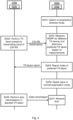
- Radio transceiver device 200a switches to a polarization diversity mode, for example by activating the time delay component 440 (with both switches 442a, 442b up in Fig. 3 ).
- Radio transceiver device 200b performs a transmission beam sweep whilst transmitting CSI-RS. A burst of CSI-RS is thus transmitted in different transmission beams.
- Radio transceiver device 200a receives the CSI-RS and performs RSRP measurements over the whole frequency band. Radio transceiver device 200a further determines which of the transmission beams was received with highest RSRP, thus determining the best transmission beam.
- Radio transceiver device 200a reports the index to the thus best transmission beam to radio transceiver device 200b.
- Radio transceiver device 200a switches to normal polarization mode, for example by deactivating the time delay component 440 (with both switches 442a, 442b down in Fig. 3 ).
- Radio transceiver device 200b transmits data towards radio transceiver device 200a using the reported best transmission beam.
- Radio transceiver device 200a receives the data.
- Fig. 6 schematically illustrates, in terms of a number of functional units, the components of a radio transceiver device 200a according to an embodiment.
- Processing circuitry 210 is provided using any combination of one or more of a suitable central processing unit (CPU), multiprocessor, microcontroller, digital signal processor (DSP), etc., capable of executing software instructions stored in a computer program product 810 (as in Fig. 8 ), e.g. in the form of a storage medium 230.
- the processing circuitry 210 may further be provided as at least one application specific integrated circuit (ASIC), or field programmable gate array (FPGA).
- ASIC application specific integrated circuit
- FPGA field programmable gate array
- the processing circuitry 210 is configured to cause radio transceiver device 200a to perform a set of operations, or steps, S102-S110, as disclosed above.
- the storage medium 230 may store the set of operations
- the processing circuitry 210 may be configured to retrieve the set of operations from the storage medium 230 to cause radio transceiver device 200a to perform the set of operations.
- the set of operations may be provided as a set of executable instructions.
- Radio transceiver device 200a may further comprise a communications interface 220 at least configured for communications with communications with another radio transceiver device 200b.
- the communications interface 220 may comprise one or more transmitters and receivers, comprising analogue and digital components. Signals, such as reference signals as well as data signals, could be transmitted from, and received by, a TRP 400a of radio transceiver device 200a.
- the TRP 400a could form an integral part of radio transceiver device 200a or be physically separated from radio transceiver device 200a.
- the communications interface 220 might thus optionally comprise the TRP 400a.
- the processing circuitry 210 controls the general operation of radio transceiver device 200a e.g. by sending data and control signals to the communications interface 220 and the storage medium 230, by receiving data and reports from the communications interface 220, and by retrieving data and instructions from the storage medium 230.
- Other components, as well as the related functionality, of radio transceiver device 200a are omitted in order not to obscure the concepts presented herein.
- Fig. 7 schematically illustrates, in terms of a number of functional modules, the components of a radio transceiver device 200a according to an embodiment.
- Radio transceiver device 200a of Fig. 7 comprises a receive module 210a configured to perform step S102.
- Radio transceiver device 200a of Fig. 7 comprises a receive module 210a configured to perform step S102.
- a measure module 210b configured to perform step S102a
- a determine module 210c configured to perform step S102b
- a measure module 210d configured to perform step S102c
- a transmit module 210e configured to perform step S104
- a determine module 210f configured to perform step S106
- an apply module 210g configured to perform step S108
- a receive module 210h configured to perform step S110.
- each functional module 210a-210h may in one embodiment be implemented only in hardware and in another embodiment with the help of software, i.e., the latter embodiment having computer program instructions stored on the storage medium 230 which when run on the processing circuitry makes radio transceiver device 200a perform the corresponding steps mentioned above in conjunction with Fig 7 .
- the modules correspond to parts of a computer program, they do not need to be separate modules therein, but the way in which they are implemented in software is dependent on the programming language used.
- one or more or all functional modules 210a-210h may be implemented by the processing circuitry 210, possibly in cooperation with the communications interface 220 and/or the storage medium 230.
- the processing circuitry 210 may thus be configured to from the storage medium 230 fetch instructions as provided by a functional module 210a-210h and to execute these instructions, thereby performing any steps as disclosed herein.
- Radio transceiver device 200a may be provided as a standalone device or as a part of at least one further device. Examples of devices in which the functionality of radio transceiver device 200a might be provided have been given above with reference to Fig. 1 .
- a first portion of the instructions performed by radio transceiver device 200a may be executed in a first device, and a second portion of the of the instructions performed by radio transceiver device 200a may be executed in a second device; the herein disclosed embodiments are not limited to any particular number of devices on which the instructions performed by radio transceiver device 200a may be executed.
- the methods according to the herein disclosed embodiments are suitable to be performed by a radio transceiver device 200a residing in a cloud computational environment. Therefore, although a single processing circuitry 210 is illustrated in Fig. 6 the processing circuitry 210 may be distributed among a plurality of devices, or nodes. The same applies to the functional modules 210a-210h of Fig. 7 and the computer program 820 of Fig. 8 (see below).
- Fig. 8 shows one example of a computer program product 810 comprising computer readable storage medium 830.
- a computer program 820 can be stored, which computer program 820 can cause the processing circuitry 210 and thereto operatively coupled entities and devices, such as the communications interface 220 and the storage medium 230, to execute methods according to embodiments described herein.
- the computer program 820 and/or computer program product 810 may thus provide means for performing any steps as herein disclosed.
- the computer program product 810 is illustrated as an optical disc, such as a CD (compact disc) or a DVD (digital versatile disc) or a Blu-Ray disc.
- the computer program product 810 could also be embodied as a memory, such as a random access memory (RAM), a read-only memory (ROM), an erasable programmable read-only memory (EPROM), or an electrically erasable programmable read-only memory (EEPROM) and more particularly as a non-volatile storage medium of a device in an external memory such as a USB (Universal Serial Bus) memory or a Flash memory, such as a compact Flash memory.
- the computer program 820 is here schematically shown as a track on the depicted optical disk, the computer program 820 can be stored in any way which is suitable for the computer program product 810.
Landscapes
- Engineering & Computer Science (AREA)
- Signal Processing (AREA)
- Computer Networks & Wireless Communication (AREA)
- Mobile Radio Communication Systems (AREA)
- Radio Transmission System (AREA)
Claims (13)
- Procédé pour participer à une gestion de faisceau, le procédé étant exécuté par un dispositif émetteur-récepteur radio (200a), le procédé comprenant les étapes consistant à :recevoir (S102) un signal de référence à partir d'un autre dispositif émetteur-récepteur radio (200b) en tant qu'élément participant à la gestion de faisceau,dans lequel le signal de référence occupe des ressources temps/fréquence qui s'étendent sur un premier intervalle de fréquence,dans lequel le signal de référence est reçu dans un faisceau de réception (150, 150a, 150b), etdans lequel le faisceau de réception (150, 150a, 150b) présente une polarisation dépendant de la fréquence sur le premier intervalle de fréquence, et dans lequel la polarisation dépendant de la fréquence change sur le premier intervalle de fréquence,caractérisé en ce que le signal de référence est reçu à l'aide d'un premier ensemble d'éléments d'antenne (430a) d'une première polarisation et, avec une valeur de retard de temps δ, au niveau d'un second ensemble d'éléments d'antenne (430b) d'une seconde polarisation, la valeur de retard de temps δ provoquant la polarisation dépendant de la fréquence sur le premier intervalle de fréquence, eten ce que la valeur de retard de temps δ est mise en oeuvre dans un composant de retard de temps (440) dans le dispositif émetteur-récepteur radio (200a).
- Procédé selon la revendication 1, dans lequel au moins deux occurrences du signal de référence sont reçues dans le faisceau de réception (150, 150a, 150b), dans lequel chaque occurrence correspond à un faisceau de transmission différent (140, 140a, 140b) dans lequel le signal de référence est transmis depuis ledit autre dispositif émetteur-récepteur radio (200b), le procédé comprenant en outre l'étape consistant à :
mesurer (S102c) une puissance reçue de chaque occurrence du signal de référence sur le premier intervalle de fréquence lors de la réception du signal de référence. - Procédé selon la revendication 2, comprenant en outre l'étape consistant à :
transmettre (S104) un rapport audit autre dispositif émetteur-récepteur radio (200b), le rapport indiquant à quelle occurrence le signal de référence a été reçu avec la puissance reçue la plus élevée. - Procédé selon l'une quelconque des revendications précédentes, comprenant en outre l'étape consistant à :recevoir (S110) des données et/ou un signal de commande à partir dudit autre dispositif émetteur-récepteur radio (200b), dans lequel les données et/ou un signal de commande occupent des ressources temps/fréquence qui s'étendent sur un second intervalle de fréquence, etdans lequel les données et/ou un signal de commande sont reçus dans un faisceau de réception (150, 150a, 150b) présentant une polarisation indépendante de la fréquence sur le second intervalle de fréquence.
- Procédé selon l'une quelconque des revendications précédentes, comprenant en outre l'étape consistant à :mesurer (S102a) une puissance reçue du signal de référence sur le premier intervalle de fréquence lors de la réception du signal de référence ;déterminer (S102b) à quelle polarisation dépendant de la fréquence dans le premier intervalle de fréquence le signal de référence a été reçu avec la puissance reçue la plus élevée.
- Procédé selon la revendication 5, dans lequel la polarisation dépendant de la fréquence dans le premier intervalle de fréquence à laquelle le signal de référence a été reçu avec la puissance reçue la plus élevée définit un état de polarisation, le procédé comprenant en outre les étapes consistant à :déterminer (S106) un ensemble de réglages d'ajustement de phase correspondant à l'état de polarisation ; etappliquer (S108) l'ensemble de réglages d'ajustement de phase à des déphaseurs (450) du dispositif émetteur-récepteur radio (200a).
- Procédé selon la revendication 6, dans lequel l'ensemble de réglages d'ajustement de phase est appliqué lors de la réception des données et/ou d'un signal de commande à partir dudit autre dispositif émetteur-récepteur radio (200b).
- Procédé selon l'une quelconque des revendications précédentes, dans lequel le signal de référence est reçu dans au moins deux faisceaux de réception (150, 150a, 150b), et dans lequel chacun des deux faisceaux de réception (150, 150a, 150b) présente une polarisation dépendant de la fréquence sur le premier intervalle de fréquence.
- Procédé selon l'une quelconque des revendications précédentes, dans lequel la valeur de retard de temps δ est déterminée selon δ= α/(2π·B), où B est le premier intervalle de fréquence en Hertz, et α est le déphasage total en radians de la polarisation sur le premier intervalle de fréquence B.
- Procédé selon l'une quelconque des revendications précédentes, dans lequel le composant de retard de temps (440) est connecté de manière opérationnelle entre une chaîne de bande de base (410) et tous les éléments d'antenne soit du premier ensemble d'éléments d'antenne (430a) soit du second ensemble d'éléments d'antenne (430b).
- Procédé selon l'une quelconque des revendications précédentes, dans lequel le premier intervalle de fréquence est divisé en au moins deux sous-bandes de fréquence, et dans lequel la polarisation change entre deux sous-bandes de fréquence voisines.
- Dispositif émetteur-récepteur radio (200a) pour participer à une gestion de faisceau, le dispositif émetteur-récepteur radio (200a) comprenant des circuits de traitement (210), les circuits de traitement étant configurés pour amener le dispositif émetteur-récepteur radio (200a) à :recevoir un signal de référence à partir d'un autre dispositif émetteur-récepteur radio (200b) en tant qu'élément participant à la gestion de faisceau,dans lequel le signal de référence occupe des ressources temps/fréquence qui s'étendent sur un premier intervalle de fréquence,dans lequel le signal de référence est reçu dans un faisceau de réception (150, 150a, 150b), etdans lequel le faisceau de réception (150, 150a, 150b) présente une polarisation dépendant de la fréquence sur le premier intervalle de fréquence, et dans lequel la polarisation dépendant de la fréquence change sur le premier intervalle de fréquence,caractérisé en ce que le signal de référence est reçu à l'aide d'un premier ensemble d'éléments d'antenne (430a) d'une première polarisation et, avec une valeur de retard de temps δ, au niveau d'un second ensemble d'éléments d'antenne (430b) d'une seconde polarisation, la valeur de retard de temps δ provoquant la polarisation dépendant de la fréquence sur le premier intervalle de fréquence, eten ce que la valeur de retard de temps δ est mise en oeuvre dans un composant de retard de temps (440) dans le dispositif émetteur-récepteur radio (200a).
- Programme informatique (820) comprenant un code informatique qui, lorsqu'il est exécuté sur des circuits de traitement (210) d'un dispositif émetteur-récepteur radio (200a), amène le dispositif émetteur-récepteur radio (200a) à :recevoir (S102) un signal de référence à partir d'un autre dispositif émetteur-récepteur radio (200b) en tant qu'élément participant à la gestion de faisceau,dans lequel le signal de référence occupe des ressources temps/fréquence qui s'étendent sur un premier intervalle de fréquence,dans lequel le signal de référence est reçu dans un faisceau de réception (150, 150a, 150b), etdans lequel le faisceau de réception (150, 150a, 150b) présente une polarisation dépendant de la fréquence sur le premier intervalle de fréquence, et dans lequel la polarisation dépendant de la fréquence change sur le premier intervalle de fréquence,caractérisé en ce que le signal de référence est reçu à l'aide d'un premier ensemble d'éléments d'antenne (430a) d'une première polarisation et, avec une valeur de retard de temps δ, au niveau d'un second ensemble d'éléments d'antenne (430b) d'une seconde polarisation, la valeur de retard de temps δ provoquant la polarisation dépendant de la fréquence sur le premier intervalle de fréquence, eten ce que la valeur de retard de temps δ est mise en oeuvre dans un composant de retard de temps (440) dans le dispositif émetteur-récepteur radio (200a).
Applications Claiming Priority (1)
| Application Number | Priority Date | Filing Date | Title |
|---|---|---|---|
| PCT/EP2018/051511 WO2019145012A1 (fr) | 2018-01-23 | 2018-01-23 | Gestion de faisceau d'un dispositif émetteur-récepteur radio |
Publications (3)
| Publication Number | Publication Date |
|---|---|
| EP3732796A1 EP3732796A1 (fr) | 2020-11-04 |
| EP3732796B1 true EP3732796B1 (fr) | 2023-08-09 |
| EP3732796C0 EP3732796C0 (fr) | 2023-08-09 |
Family
ID=61148192
Family Applications (1)
| Application Number | Title | Priority Date | Filing Date |
|---|---|---|---|
| EP18702634.9A Active EP3732796B1 (fr) | 2018-01-23 | 2018-01-23 | Gestion de faisceau d'un dispositif émetteur-récepteur radio |
Country Status (3)
| Country | Link |
|---|---|
| US (1) | US10911127B2 (fr) |
| EP (1) | EP3732796B1 (fr) |
| WO (1) | WO2019145012A1 (fr) |
Families Citing this family (4)
| Publication number | Priority date | Publication date | Assignee | Title |
|---|---|---|---|---|
| WO2017207042A1 (fr) * | 2016-06-01 | 2017-12-07 | Sony Mobile Communications Inc. | Coexistence de communication radio et de recherche par sondage radar |
| CN111201723A (zh) * | 2017-10-10 | 2020-05-26 | 瑞典爱立信有限公司 | 无线电收发机设备的波束管理 |
| US20220304061A1 (en) * | 2021-03-17 | 2022-09-22 | Qualcomm Incorporated | Increasing random access coverage |
| US20230217289A1 (en) * | 2022-01-05 | 2023-07-06 | Qualcomm Incorporated | Layer 3 measurement associated with dedicated polarization |
Family Cites Families (14)
| Publication number | Priority date | Publication date | Assignee | Title |
|---|---|---|---|---|
| WO2006017850A2 (fr) | 2004-08-12 | 2006-02-16 | Interdigital Technology Corporation | Dispositif permettant de reduire la correlation d'antennes et procede associe |
| ES2361200T3 (es) | 2007-03-21 | 2011-06-14 | Alcatel Lucent | Método para determinar técnicas de transmisión mimo, estación de base y terminal móvil. |
| US8994588B2 (en) | 2009-10-28 | 2015-03-31 | Telefonaktiebolaget L M Ericsson (Publ) | Method of designing weight vectors for a dual beam antenna with orthogonal polarizations |
| JP6629236B2 (ja) * | 2014-05-08 | 2020-01-15 | テレフオンアクチーボラゲット エルエム エリクソン(パブル) | デュアル偏波アンテナ構成を用いたビーム形成 |
| JP6457108B2 (ja) | 2015-03-06 | 2019-01-23 | テレフオンアクチーボラゲット エルエム エリクソン(パブル) | アンテナ装置を使用するビーム形成 |
| US9716541B2 (en) | 2015-09-15 | 2017-07-25 | Qualcomm Incorporated | Systems and methods for reducing interference using polarization diversity |
| US10666346B2 (en) * | 2015-11-11 | 2020-05-26 | Telefonaktiebolaget Lm Ericsson (Publ) | Network node, wireless device, and methods for beam management |
| US10623075B2 (en) | 2016-04-02 | 2020-04-14 | University Of Notre Dame Du Lac | Linear combinations of transmit signals by a receiver |
| US10804952B2 (en) * | 2016-04-11 | 2020-10-13 | University Of Notre Dame Du Lac | Enhanced cosite transmitter-receiver isolation |
| WO2018128180A1 (fr) * | 2017-01-06 | 2018-07-12 | 株式会社Nttドコモ | Terminal d'utilisateur et procédé de communication sans fil |
| CN110168953A (zh) | 2017-01-12 | 2019-08-23 | 瑞典爱立信有限公司 | 双极化波束成形 |
| KR102355817B1 (ko) * | 2017-01-17 | 2022-01-26 | 삼성전자 주식회사 | 이동 통신 시스템에서의 반영속적 채널 상태 보고 방법 및 장치 |
| WO2018174636A2 (fr) * | 2017-03-23 | 2018-09-27 | 엘지전자 (주) | Procédé d'émission ou de réception d'informations d'état de canal dans un système de communication sans fil et appareil associé |
| EP3692646A1 (fr) * | 2017-12-08 | 2020-08-12 | Telefonaktiebolaget LM Ericsson (publ) | Gestion de faisceau dans un réseau de communications |
-
2018
- 2018-01-23 US US15/751,762 patent/US10911127B2/en active Active
- 2018-01-23 EP EP18702634.9A patent/EP3732796B1/fr active Active
- 2018-01-23 WO PCT/EP2018/051511 patent/WO2019145012A1/fr unknown
Also Published As
| Publication number | Publication date |
|---|---|
| WO2019145012A1 (fr) | 2019-08-01 |
| EP3732796C0 (fr) | 2023-08-09 |
| EP3732796A1 (fr) | 2020-11-04 |
| US10911127B2 (en) | 2021-02-02 |
| US20200212986A1 (en) | 2020-07-02 |
Similar Documents
| Publication | Publication Date | Title |
|---|---|---|
| EP3732796B1 (fr) | Gestion de faisceau d'un dispositif émetteur-récepteur radio | |
| US10681674B2 (en) | Beam training for a radio transceiver device | |
| US10993122B2 (en) | Beam management procedure in a communications network | |
| US10356787B2 (en) | Beam training of a radio transceiver device | |
| US10673587B2 (en) | Beam management for a radio transceiver device | |
| EP3732797B1 (fr) | Sélection de faisceau d'un dispositif émetteur-récepteur radio | |
| CN109565315B (zh) | 利用天线阵列发送和接收参考信令的网络节点、终端及方法 | |
| US11550017B2 (en) | Angle of arrival estimation in a radio communications network | |
| US11271696B2 (en) | Beam management of a radio transceiver device | |
| US20220070790A1 (en) | Transmission of uplink reference signals | |
| EP3676964B1 (fr) | Gestion de faisceau dans une cellule | |
| EP3516783B1 (fr) | Procédure de recherche de faisceau | |
| CN112585883B (zh) | 来自网络节点的波束成形的信号传输 | |
| CN110663198B (zh) | 用于确定通信网络中的电相位关系的方法、装置和介质 | |
| US20230412237A1 (en) | Polarization based beam selection process | |
| US20230370861A1 (en) | Method and network node for signalling tci states to user equipment |
Legal Events
| Date | Code | Title | Description |
|---|---|---|---|
| STAA | Information on the status of an ep patent application or granted ep patent |
Free format text: STATUS: UNKNOWN |
|
| STAA | Information on the status of an ep patent application or granted ep patent |
Free format text: STATUS: THE INTERNATIONAL PUBLICATION HAS BEEN MADE |
|
| PUAI | Public reference made under article 153(3) epc to a published international application that has entered the european phase |
Free format text: ORIGINAL CODE: 0009012 |
|
| STAA | Information on the status of an ep patent application or granted ep patent |
Free format text: STATUS: REQUEST FOR EXAMINATION WAS MADE |
|
| STAA | Information on the status of an ep patent application or granted ep patent |
Free format text: STATUS: EXAMINATION IS IN PROGRESS |
|
| STAA | Information on the status of an ep patent application or granted ep patent |
Free format text: STATUS: EXAMINATION IS IN PROGRESS |
|
| 17P | Request for examination filed |
Effective date: 20200721 |
|
| AK | Designated contracting states |
Kind code of ref document: A1 Designated state(s): AL AT BE BG CH CY CZ DE DK EE ES FI FR GB GR HR HU IE IS IT LI LT LU LV MC MK MT NL NO PL PT RO RS SE SI SK SM TR |
|
| AX | Request for extension of the european patent |
Extension state: BA ME |
|
| 17Q | First examination report despatched |
Effective date: 20201030 |
|
| DAV | Request for validation of the european patent (deleted) | ||
| DAX | Request for extension of the european patent (deleted) | ||
| STAA | Information on the status of an ep patent application or granted ep patent |
Free format text: STATUS: EXAMINATION IS IN PROGRESS |
|
| GRAP | Despatch of communication of intention to grant a patent |
Free format text: ORIGINAL CODE: EPIDOSNIGR1 |
|
| STAA | Information on the status of an ep patent application or granted ep patent |
Free format text: STATUS: GRANT OF PATENT IS INTENDED |
|
| INTG | Intention to grant announced |
Effective date: 20230405 |
|
| GRAS | Grant fee paid |
Free format text: ORIGINAL CODE: EPIDOSNIGR3 |
|
| GRAA | (expected) grant |
Free format text: ORIGINAL CODE: 0009210 |
|
| STAA | Information on the status of an ep patent application or granted ep patent |
Free format text: STATUS: THE PATENT HAS BEEN GRANTED |
|
| AK | Designated contracting states |
Kind code of ref document: B1 Designated state(s): AL AT BE BG CH CY CZ DE DK EE ES FI FR GB GR HR HU IE IS IT LI LT LU LV MC MK MT NL NO PL PT RO RS SE SI SK SM TR |
|
| REG | Reference to a national code |
Ref country code: GB Ref legal event code: FG4D |
|
| REG | Reference to a national code |
Ref country code: CH Ref legal event code: EP |
|
| REG | Reference to a national code |
Ref country code: IE Ref legal event code: FG4D |
|
| REG | Reference to a national code |
Ref country code: DE Ref legal event code: R096 Ref document number: 602018054932 Country of ref document: DE |
|
| U01 | Request for unitary effect filed |
Effective date: 20230822 |
|
| U07 | Unitary effect registered |
Designated state(s): AT BE BG DE DK EE FI FR IT LT LU LV MT NL PT SE SI Effective date: 20230828 |
|
| PG25 | Lapsed in a contracting state [announced via postgrant information from national office to epo] |
Ref country code: GR Free format text: LAPSE BECAUSE OF FAILURE TO SUBMIT A TRANSLATION OF THE DESCRIPTION OR TO PAY THE FEE WITHIN THE PRESCRIBED TIME-LIMIT Effective date: 20231110 |
|
| PG25 | Lapsed in a contracting state [announced via postgrant information from national office to epo] |
Ref country code: IS Free format text: LAPSE BECAUSE OF FAILURE TO SUBMIT A TRANSLATION OF THE DESCRIPTION OR TO PAY THE FEE WITHIN THE PRESCRIBED TIME-LIMIT Effective date: 20231209 |
|
| PG25 | Lapsed in a contracting state [announced via postgrant information from national office to epo] |
Ref country code: RS Free format text: LAPSE BECAUSE OF FAILURE TO SUBMIT A TRANSLATION OF THE DESCRIPTION OR TO PAY THE FEE WITHIN THE PRESCRIBED TIME-LIMIT Effective date: 20230809 Ref country code: NO Free format text: LAPSE BECAUSE OF FAILURE TO SUBMIT A TRANSLATION OF THE DESCRIPTION OR TO PAY THE FEE WITHIN THE PRESCRIBED TIME-LIMIT Effective date: 20231109 Ref country code: IS Free format text: LAPSE BECAUSE OF FAILURE TO SUBMIT A TRANSLATION OF THE DESCRIPTION OR TO PAY THE FEE WITHIN THE PRESCRIBED TIME-LIMIT Effective date: 20231209 Ref country code: HR Free format text: LAPSE BECAUSE OF FAILURE TO SUBMIT A TRANSLATION OF THE DESCRIPTION OR TO PAY THE FEE WITHIN THE PRESCRIBED TIME-LIMIT Effective date: 20230809 Ref country code: GR Free format text: LAPSE BECAUSE OF FAILURE TO SUBMIT A TRANSLATION OF THE DESCRIPTION OR TO PAY THE FEE WITHIN THE PRESCRIBED TIME-LIMIT Effective date: 20231110 |
|
| U20 | Renewal fee paid [unitary effect] |
Year of fee payment: 7 Effective date: 20240125 |
|
| PG25 | Lapsed in a contracting state [announced via postgrant information from national office to epo] |
Ref country code: PL Free format text: LAPSE BECAUSE OF FAILURE TO SUBMIT A TRANSLATION OF THE DESCRIPTION OR TO PAY THE FEE WITHIN THE PRESCRIBED TIME-LIMIT Effective date: 20230809 |
|
| PG25 | Lapsed in a contracting state [announced via postgrant information from national office to epo] |
Ref country code: ES Free format text: LAPSE BECAUSE OF FAILURE TO SUBMIT A TRANSLATION OF THE DESCRIPTION OR TO PAY THE FEE WITHIN THE PRESCRIBED TIME-LIMIT Effective date: 20230809 |
|
| PG25 | Lapsed in a contracting state [announced via postgrant information from national office to epo] |
Ref country code: SM Free format text: LAPSE BECAUSE OF FAILURE TO SUBMIT A TRANSLATION OF THE DESCRIPTION OR TO PAY THE FEE WITHIN THE PRESCRIBED TIME-LIMIT Effective date: 20230809 Ref country code: RO Free format text: LAPSE BECAUSE OF FAILURE TO SUBMIT A TRANSLATION OF THE DESCRIPTION OR TO PAY THE FEE WITHIN THE PRESCRIBED TIME-LIMIT Effective date: 20230809 Ref country code: ES Free format text: LAPSE BECAUSE OF FAILURE TO SUBMIT A TRANSLATION OF THE DESCRIPTION OR TO PAY THE FEE WITHIN THE PRESCRIBED TIME-LIMIT Effective date: 20230809 Ref country code: CZ Free format text: LAPSE BECAUSE OF FAILURE TO SUBMIT A TRANSLATION OF THE DESCRIPTION OR TO PAY THE FEE WITHIN THE PRESCRIBED TIME-LIMIT Effective date: 20230809 Ref country code: SK Free format text: LAPSE BECAUSE OF FAILURE TO SUBMIT A TRANSLATION OF THE DESCRIPTION OR TO PAY THE FEE WITHIN THE PRESCRIBED TIME-LIMIT Effective date: 20230809 |
|
| PGFP | Annual fee paid to national office [announced via postgrant information from national office to epo] |
Ref country code: GB Payment date: 20240129 Year of fee payment: 7 |