EP3632000B1 - Determination of electrical phase relation in a communications network - Google Patents
Determination of electrical phase relation in a communications network Download PDFInfo
- Publication number
- EP3632000B1 EP3632000B1 EP17727875.1A EP17727875A EP3632000B1 EP 3632000 B1 EP3632000 B1 EP 3632000B1 EP 17727875 A EP17727875 A EP 17727875A EP 3632000 B1 EP3632000 B1 EP 3632000B1
- Authority
- EP
- European Patent Office
- Prior art keywords
- polarization
- arrival
- angle
- receive beams
- ports
- Prior art date
- Legal status (The legal status is an assumption and is not a legal conclusion. Google has not performed a legal analysis and makes no representation as to the accuracy of the status listed.)
- Active
Links
- 238000004891 communication Methods 0.000 title description 24
- 230000010287 polarization Effects 0.000 claims description 69
- 238000000034 method Methods 0.000 claims description 48
- 238000004590 computer program Methods 0.000 claims description 33
- 238000005259 measurement Methods 0.000 claims description 24
- 238000012545 processing Methods 0.000 claims description 19
- 238000003860 storage Methods 0.000 claims description 19
- 239000011159 matrix material Substances 0.000 claims description 14
- 239000013598 vector Substances 0.000 claims description 12
- 230000006870 function Effects 0.000 description 26
- 230000005540 biological transmission Effects 0.000 description 9
- 230000010363 phase shift Effects 0.000 description 8
- 238000003491 array Methods 0.000 description 5
- 238000010408 sweeping Methods 0.000 description 5
- 238000010586 diagram Methods 0.000 description 4
- 238000009826 distribution Methods 0.000 description 3
- 230000003287 optical effect Effects 0.000 description 3
- 230000001419 dependent effect Effects 0.000 description 2
- 230000007246 mechanism Effects 0.000 description 2
- 238000011084 recovery Methods 0.000 description 2
- 230000011664 signaling Effects 0.000 description 2
- 230000003044 adaptive effect Effects 0.000 description 1
- 239000000470 constituent Substances 0.000 description 1
- 230000009977 dual effect Effects 0.000 description 1
- 230000000694 effects Effects 0.000 description 1
- 238000005516 engineering process Methods 0.000 description 1
- 238000003780 insertion Methods 0.000 description 1
- 230000037431 insertion Effects 0.000 description 1
- 230000007774 longterm Effects 0.000 description 1
- 238000004519 manufacturing process Methods 0.000 description 1
- 238000010295 mobile communication Methods 0.000 description 1
- 238000012544 monitoring process Methods 0.000 description 1
- 230000000737 periodic effect Effects 0.000 description 1
- 230000002085 persistent effect Effects 0.000 description 1
- 238000000926 separation method Methods 0.000 description 1
- 238000012883 sequential measurement Methods 0.000 description 1
- 239000007787 solid Substances 0.000 description 1
Images


Classifications
-
- H—ELECTRICITY
- H01—ELECTRIC ELEMENTS
- H01Q—ANTENNAS, i.e. RADIO AERIALS
- H01Q3/00—Arrangements for changing or varying the orientation or the shape of the directional pattern of the waves radiated from an antenna or antenna system
- H01Q3/26—Arrangements for changing or varying the orientation or the shape of the directional pattern of the waves radiated from an antenna or antenna system varying the relative phase or relative amplitude of energisation between two or more active radiating elements; varying the distribution of energy across a radiating aperture
- H01Q3/267—Phased-array testing or checking devices
-
- H—ELECTRICITY
- H04—ELECTRIC COMMUNICATION TECHNIQUE
- H04B—TRANSMISSION
- H04B7/00—Radio transmission systems, i.e. using radiation field
- H04B7/02—Diversity systems; Multi-antenna system, i.e. transmission or reception using multiple antennas
- H04B7/04—Diversity systems; Multi-antenna system, i.e. transmission or reception using multiple antennas using two or more spaced independent antennas
- H04B7/06—Diversity systems; Multi-antenna system, i.e. transmission or reception using multiple antennas using two or more spaced independent antennas at the transmitting station
- H04B7/0613—Diversity systems; Multi-antenna system, i.e. transmission or reception using multiple antennas using two or more spaced independent antennas at the transmitting station using simultaneous transmission
- H04B7/0615—Diversity systems; Multi-antenna system, i.e. transmission or reception using multiple antennas using two or more spaced independent antennas at the transmitting station using simultaneous transmission of weighted versions of same signal
- H04B7/0617—Diversity systems; Multi-antenna system, i.e. transmission or reception using multiple antennas using two or more spaced independent antennas at the transmitting station using simultaneous transmission of weighted versions of same signal for beam forming
-
- G—PHYSICS
- G01—MEASURING; TESTING
- G01S—RADIO DIRECTION-FINDING; RADIO NAVIGATION; DETERMINING DISTANCE OR VELOCITY BY USE OF RADIO WAVES; LOCATING OR PRESENCE-DETECTING BY USE OF THE REFLECTION OR RERADIATION OF RADIO WAVES; ANALOGOUS ARRANGEMENTS USING OTHER WAVES
- G01S3/00—Direction-finders for determining the direction from which infrasonic, sonic, ultrasonic, or electromagnetic waves, or particle emission, not having a directional significance, are being received
- G01S3/02—Direction-finders for determining the direction from which infrasonic, sonic, ultrasonic, or electromagnetic waves, or particle emission, not having a directional significance, are being received using radio waves
- G01S3/04—Details
- G01S3/043—Receivers
-
- G—PHYSICS
- G01—MEASURING; TESTING
- G01S—RADIO DIRECTION-FINDING; RADIO NAVIGATION; DETERMINING DISTANCE OR VELOCITY BY USE OF RADIO WAVES; LOCATING OR PRESENCE-DETECTING BY USE OF THE REFLECTION OR RERADIATION OF RADIO WAVES; ANALOGOUS ARRANGEMENTS USING OTHER WAVES
- G01S3/00—Direction-finders for determining the direction from which infrasonic, sonic, ultrasonic, or electromagnetic waves, or particle emission, not having a directional significance, are being received
- G01S3/02—Direction-finders for determining the direction from which infrasonic, sonic, ultrasonic, or electromagnetic waves, or particle emission, not having a directional significance, are being received using radio waves
- G01S3/14—Systems for determining direction or deviation from predetermined direction
- G01S3/16—Systems for determining direction or deviation from predetermined direction using amplitude comparison of signals derived sequentially from receiving antennas or antenna systems having differently-oriented directivity characteristics or from an antenna system having periodically-varied orientation of directivity characteristic
- G01S3/20—Systems for determining direction or deviation from predetermined direction using amplitude comparison of signals derived sequentially from receiving antennas or antenna systems having differently-oriented directivity characteristics or from an antenna system having periodically-varied orientation of directivity characteristic derived by sampling signal received by an antenna system having periodically-varied orientation of directivity characteristic
-
- H—ELECTRICITY
- H01—ELECTRIC ELEMENTS
- H01Q—ANTENNAS, i.e. RADIO AERIALS
- H01Q21/00—Antenna arrays or systems
- H01Q21/24—Combinations of antenna units polarised in different directions for transmitting or receiving circularly and elliptically polarised waves or waves linearly polarised in any direction
-
- H—ELECTRICITY
- H01—ELECTRIC ELEMENTS
- H01Q—ANTENNAS, i.e. RADIO AERIALS
- H01Q3/00—Arrangements for changing or varying the orientation or the shape of the directional pattern of the waves radiated from an antenna or antenna system
- H01Q3/26—Arrangements for changing or varying the orientation or the shape of the directional pattern of the waves radiated from an antenna or antenna system varying the relative phase or relative amplitude of energisation between two or more active radiating elements; varying the distribution of energy across a radiating aperture
- H01Q3/30—Arrangements for changing or varying the orientation or the shape of the directional pattern of the waves radiated from an antenna or antenna system varying the relative phase or relative amplitude of energisation between two or more active radiating elements; varying the distribution of energy across a radiating aperture varying the relative phase between the radiating elements of an array
- H01Q3/34—Arrangements for changing or varying the orientation or the shape of the directional pattern of the waves radiated from an antenna or antenna system varying the relative phase or relative amplitude of energisation between two or more active radiating elements; varying the distribution of energy across a radiating aperture varying the relative phase between the radiating elements of an array by electrical means
- H01Q3/36—Arrangements for changing or varying the orientation or the shape of the directional pattern of the waves radiated from an antenna or antenna system varying the relative phase or relative amplitude of energisation between two or more active radiating elements; varying the distribution of energy across a radiating aperture varying the relative phase between the radiating elements of an array by electrical means with variable phase-shifters
Definitions
- the TRP at the network side uses narrow beams for transmission
- at least one of the narrow transmission beams is assumed to be discovered and monitored for each served wireless device at the user side. This process of discovering and monitoring is referred to as beam management.
- the network node uses measurements (such as received reference signal power), as obtained and reported by the served wireless devices, on downlink reference signals such as channel state information reference signals (CSI-RS).
- CSI-RS channel state information reference signals
- the beam pair for which the highest received reference signal power was obtained is then used as the active beam pair link.
- a beam recovery procedure can be initiated to reestablish the beam connection.
- Such beam recovery procedure could, for example, comprise sweeping through all different combinations of TRP beams and wireless device beams. When there are many candidate beams at both the TRP and the wireless device, such beam sweeping procedure could be costly in terms of time consumption and overhead signaling. Further, in some scenarios, a wireless device could be operatively connected to different TRPs in downlink and uplink, which thus might require separate beam management procedures for downlink and uplink.
- Nechaev Yuri et al "Impact on beamspace processing on accuracy of DOA estimation using MUSIC and Capon methods", 2015 IEEE 38th International Conference on Telecommunications and Signal Processing , relates to superresolution direction-of-arrival methods such as MUSIC, CAPON after beamspace processing, i.e., BS-MUSIC and BS-Capon.
- An object of embodiments herein is to enable efficient beam management.
- the radio access network no is operatively connected to a core network 120.
- the core network 120 is in turn operatively connected to a service network 130, such as the Internet.
- Radio transceiver device 300 is thereby, via the TRP 205 and radio transceiver device 200, enabled to access services of, and exchange data with, the service network 130.
Description
- Embodiments presented herein relate to a method, a radio transceiver device, a computer program, and a computer program product for determining an electrical phase relation between antenna elements in an antenna array.
- In communications networks, there may be a challenge to obtain good performance and capacity for a given communications protocol, its parameters and the physical environment in which the communications network is deployed.
- For example, for future generations of mobile communications systems frequency bands at many different carrier frequencies could be needed. For example, low such frequency bands could be needed to achieve sufficient network coverage for wireless devices and higher frequency bands (e.g. at millimeter wavelengths (mmW), i.e. near and above 30 GHz) could be needed to reach required network capacity. In general terms, at high frequencies the propagation properties of the radio channel are more challenging and beamforming both at the network node of the network and at the wireless devices might be required to reach a sufficient link budget.
- The wireless devices and/or the transmission and reception point (TRP) of the network node could implement beamforming by means of analog beamforming, digital beamforming, or hybrid beamforming. Each implementation has its advantages and disadvantages. A digital beamforming implementation is the most flexible implementation of the three but also the costliest due to the large number of required radio chains and baseband chains. An analog beamforming implementation is the least flexible but cheaper to manufacture due to a reduced number of radio chains and baseband chains compared to the digital beamforming implementation. A hybrid beamforming implementation is a compromise between the analog and the digital beamforming implementations. As the skilled person understands, depending on cost and performance requirements of different wireless devices, different implementations will be needed.
- In a communications network where the TRP at the network side uses narrow beams for transmission, at least one of the narrow transmission beams is assumed to be discovered and monitored for each served wireless device at the user side. This process of discovering and monitoring is referred to as beam management. In order to perform beam management the network node uses measurements (such as received reference signal power), as obtained and reported by the served wireless devices, on downlink reference signals such as channel state information reference signals (CSI-RS). The beam pair for which the highest received reference signal power was obtained is then used as the active beam pair link. In general terms, a beam pair is defined by a transmission beam at the transmitting end (such as at the TRP) and a corresponding reception beam at the receiving end (such as at the wireless device), where the transmission beam and the reception beam are selected from sets of available candidate beams so as to maximize a quality criterion (such as highest received reference signal power) for transmission from the transmitting end to the receiving end.
- In case a served wireless device loses beam connection with the TRP, for example due to blockage, a beam recovery procedure can be initiated to reestablish the beam connection. Such beam recovery procedure could, for example, comprise sweeping through all different combinations of TRP beams and wireless device beams. When there are many candidate beams at both the TRP and the wireless device, such beam sweeping procedure could be costly in terms of time consumption and overhead signaling. Further, in some scenarios, a wireless device could be operatively connected to different TRPs in downlink and uplink, which thus might require separate beam management procedures for downlink and uplink.
- Nechaev Yuri et al: "Impact on beamspace processing on accuracy of DOA estimation using MUSIC and Capon methods", 2015 IEEE 38th International Conference on Telecommunications and Signal Processing, relates to superresolution direction-of-arrival methods such as MUSIC, CAPON after beamspace processing, i.e., BS-MUSIC and BS-Capon.
- Sung-Hoon Moon et al: "A new GSC using monopulse angle estimation technique for fast target tracking", 2003 IEEE International Symposium on Phase Array Systems and Technology, relates to a generalized sidelobe canceller to solve the steering error problem caused by fast target maneuvering or array imperfections.
- Xiaojing Huang et al: "Wideband AoA Estimation and Beamforming with Hybrid Antenna Array", 2011 IEEE Global Telecommunications Conference, relates to adaptive frequency-domain AoA estimation and beamforming for wideband hybrid arrays of side-by-side sub-arrays.
- Hence, there is still a need for an improved beam management.
- An object of embodiments herein is to enable efficient beam management.
- According to a first aspect there is presented a method for determining an electrical phase relation between antenna elements in an antenna array according to
claim 1. - According to a second aspect there is presented a radio transceiver device for determining an electrical phase relation between antenna elements in an antenna array according to claim 13.
- According to a third aspect there is presented a computer program for determining an electrical phase relation between antenna elements in an antenna array according to claim 14.
- According to a fourth aspect there is presented a computer program product comprising a computer program according to the third aspect and a computer readable storage medium on which the computer program is stored. The computer readable storage medium could be a non-transitory computer readable storage medium.
- Advantageously this method, these radio transceiver devices, this computer program, and this computer program product provide efficient beam management.
- Advantageously this method, these radio transceiver devices, this computer program, and this computer program product enable the use of sequential beam sweep at the radio transceiver device to be avoided. Estimating the angle of arrival and determining the electrical phase relation in this way reduces the time to find the best analog beam pair and the overhead associated with transmission of beam finding reference signals.
- It is to be noted that any feature of the first, second, third, fourth, fifth and sixth aspects may be applied to any other aspect, wherever appropriate. Other objectives, features and advantages of the enclosed embodiments will be apparent from the following detailed disclosure, from the attached dependent claims as well as from the drawings.
- Generally, all terms used in the claims are to be interpreted according to their ordinary meaning in the technical field, unless explicitly defined otherwise herein. All references to "a/an/the element, apparatus, component, means, module, step, etc." are to be interpreted openly as referring to at least one instance of the element, apparatus, component, means, module, step, etc., unless explicitly stated otherwise. The steps of any method disclosed herein do not have to be performed in the exact order disclosed, unless explicitly stated.
- The inventive concept is now described, by way of example, with reference to the accompanying drawings, in which:
-
Fig. 1 is a schematic diagram illustrating a communications network according to embodiments; -
Fig. 2 schematically illustrates a communications interface and/or a transmission and reception point of a radio transceiver device according to embodiments; -
Figs. 3 and 4 are flowcharts of methods according to embodiments; -
Figs. 5 ,9 ,11 show magnitude and phase of discriminator functions according to embodiments; -
Figs. 6, 7 ,8 ,10 shows complex beam patterns according to embodiments; -
Fig. 12 schematically illustrates effects in time domain of sub-carrier spacing in frequency domain according to an embodiment; -
Fig. 13 is a schematic diagram showing functional units of a radio transceiver device according to an embodiment; -
Fig. 14 is a schematic diagram showing functional modules of a radio transceiver device according to an embodiment; and -
Fig. 15 shows one example of a computer program product comprising computer readable storage medium according to an embodiment. - The inventive concept will now be described more fully hereinafter with reference to the accompanying drawings, in which certain embodiments of the inventive concept are shown. This inventive concept may, however, be embodied in many different forms and should not be construed as limited to the embodiments set forth herein; rather, these embodiments are provided by way of example so that this disclosure will be thorough and complete, and will fully convey the scope of the inventive concept to those skilled in the art. Like numbers refer to like elements throughout the description. Any step or feature illustrated by dashed lines should be regarded as optional.
-
Fig. 1 is a schematic diagram illustrating acommunications network 100 where embodiments presented herein can be applied. Thecommunications network 100 could be a third generation (3G) telecommunications network, a fourth generation (4G) telecommunications network, or a fifth (5G) telecommunications network and support any 3GPP telecommunications standard. - The
communications network 100 comprises at leastradio transceiver device 200 configured to, via TRP 205, provide network access toradio transceiver device 300 in aradio access network 110. In some embodimentsradio transceiver device 300 is part of, integrated with, or collocated with, a terminal device andradio transceiver device 200 is part of, integrated with, or collocated with, a network node or theTRP 205. - The radio access network no is operatively connected to a
core network 120. Thecore network 120 is in turn operatively connected to aservice network 130, such as the Internet.Radio transceiver device 300 is thereby, via the TRP 205 andradio transceiver device 200, enabled to access services of, and exchange data with, theservice network 130. - Examples of network nodes are radio access network nodes, radio base stations, base transceiver stations, Node Bs, evolved Node Bs, gigabit Node Bs, access points, and access nodes. Examples of terminal devices are wireless devices, mobile stations, mobile phones, handsets, wireless local loop phones, user equipment (UE), smartphones, laptop computers, tablet computers, network equipped sensors, network equipped vehicles, and so-called Internet of Things devices.
- The herein disclosed embodiments can be applied at a receiving radio transceiver device implemented both as a radio access network node and a terminal device, or even as a receiving radio transceiver device implemented as a backhauling node or a sidelink node. Thus, although
radio transceiver device 200 in at least some of the herein disclosed embodiments is described as being a network node andradio transceiver device 300 is described as being a terminal device, the functionality of the herein disclosedradio transceiver device 200 could equally be implemented in a terminal device. - For ease of description,
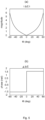
radio transceiver device 200 thus represents a receiving radio transceiver device andradio transceiver device 300 represents a transmitting radio transceiver device although bothradio transceiver devices radio transceiver device 200 is, viaTRP 205, configured to receive radio signals as transmitted by the transmittingradio transceiver device 300 in two receivebeams beams angular sector 150. Although only two receivebeams Fig. 1 , the receivingradio transceiver device 200 could be configured to communicate using a variety of beams having different shapes and widths, herein generally referred to as having different complex beam patterns. - The radio signal transmitted by the transmitting
radio transceiver device 300 is received at an angle of arrival a. Generally, the angle of arrival a is determined relative the node at which the radio signal is physically received over the radio interface. In the illustrative example ofFig. 1 this node is represented by theTRP 205. - In the illustrative example of
Fig. 2 there are twoantenna arrays polarized antenna elements analog distribution network analog distribution network chain polarized antenna elements antenna arrays radio transceiver device 200 or theTRP 205 of theradio transceiver device 200 comprises at least oneantenna array antenna arrays communications interface 220 of theradio transceiver device 200. - The
radio transceiver devices radio transceiver devices radio transceiver device 200 and the transmittingradio transceiver device 300 200, using a beam sweeping procedure could be costly in terms of time consumption and overhead signalling. - The embodiments disclosed herein relate to mechanisms for determining an electrical phase relation between
antenna elements antenna array radio transceiver device 200, a method performed by theradio transceiver device 200, a computer program product comprising code, for example in the form of a computer program, that when run on aradio transceiver device 200, causes theradio transceiver device 200 to perform the method. -
Figs. 3 and 4 are flowcharts illustrating embodiments of methods for determining an electrical phase relation betweenantenna elements antenna array radio transceiver device 200. The methods are advantageously provided ascomputer programs 1520. - Reference is now made to
Fig. 3 illustrating a method for determining an electrical phase relation betweenantenna elements antenna array radio transceiver device 200 according to an embodiment. - The method is based on the
radio transceiver device 200 measuring a received radio signal in twodifferent beams radio transceiver device 300, without needing to perform any sequential beam sweeping. Particularly, theradio transceiver device 200 is configured to perform step S102:
S102: Theradio transceiver device 200 obtains measurements of the radio signal as received in two receivebeams - As disclosed above, the two receive
beams angular sector 150. The two receivebeams - The complex beam patterns of the receive
beams angular sector 150 within which the beam finding procedure should identify which beam to use for subsequent communications with the transmittingradio transceiver device 300. - The angle of arrival a is estimated by measuring received radio signals in the two receive
beams radio transceiver device 200 is configured to perform step S104:
S104: Theradio transceiver device 200 estimates the angle of arrival a of the radio signal for at least one polarization port of each of the receivebeams beams - Here, the wording of each of the receive beams refers to the polarization port (i.e. there is at least one polarization port per receive beam). That is, the measurements in both receive
beams - The angle of arrival a is then used to determine an electrical phase relation between the
antenna elements radio transceiver device 200 is configured to perform step S106:
S106: Theradio transceiver device 200 determines, from the angle of arrival a estimated for each polarization port, an electrical phase relation betweenantenna elements antenna array - Thus instead of performing a costly sequential beam sweeping procedure the
radio transceiver device 200 is enabled to directly estimate the angle of arrival a of the received radio signal and the electrical phase relation betweenantenna elements beams antenna elements antenna array radio transceiver device 200 will now be disclosed. Reference is now made toFig. 4 illustrating methods for determining an electrical phase relation betweenantenna elements antenna array radio transceiver device 200 according to further embodiments. It is assumed that steps S102, S104, S106 are performed as described above with reference toFig. 3 and a thus repeated description thereof is therefore omitted. - According to the present invention each receive
beam beam - As disclosed above, the complex beam patterns of the receive
beams angular sector 150. In some aspects the two receivebeams angular sector 150 at most one of the receivebeam beam - Examples of ways to generate the two receive
beams - In some aspects the two receive
beams beams - One example of two receive
beams antenna array - However, generating a sum beam by summing all co-polarized antenna elements in the antenna array will generate a narrow beam (and similarly for the delta beam) which leads to a limited
angular coverage 150.Fig. 6 schematically illustrates an example of the complex beam patterns of sum and delta beams for an antenna array being a uniform linear array (ULA) having 8 antenna elements. This would make it difficult to estimate directions of arrival outside the mainlobe of the sum beam and therefore less useful for beam management purposes. - It is therefore proposed to generate two receive
beams angular sector 150 within which the radio signal is assumed to be received. For example, narrower receivebeams angular sector 150 that subsequent communications with the transmittingradio transceiver device 300 is supposed to cover. - One way to achieve this is to use only two antenna elements in the array to generate the two receive
beams beams beams Fig. 7 . - However, using a combination of phase shifts and amplitude tapering it is not possible for an antenna array that lacks support for setting the amplitude gain to zero for some of the antenna elements, e.g., in an antenna array without gain control and thus with only a phase shifter to control each antenna element. According to an embodiment the two receive
beams - In further detail, by applying principles disclosed in document
WO2011/050866A1 it is, for example, possible to generate as wide array beam widths (for the receivebeams beams WO2011/050866A1 can be applied to the analog beamforming network in order to generate the receivebeams beams - Particularly, according to an embodiment the analog beamforming in the
antenna array antenna elements beams antenna elements beams - According to an embodiment, estimating the angle of arrival a of the radio signal comprises comparing a complex amplitude of the measurements for each of the polarization ports in the two receive
beams - Aspects of the discriminator function will now be disclosed.
- In some aspects, the discriminator function is a complex function computed from the two complex beam patterns that uniquely maps a complex amplitude value to an angle of arrival a value. According to an embodiment the discriminator function is based on the complex beam patterns and, is within the given angular sector 150 a one-to-one function of the angle of arrival a. In some aspects the discriminator function is represented by a curve.
- By measuring the radio signal as received in the two receive
beams beams beams - One way to estimate the angle of arrival a from the two receive
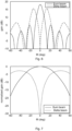
beams beams Fig. 5 shows at (a) the magnitude and at (b) the phase of this discriminator function as a function of azimuth angle. For example, if the magnitude of Δ/Σ is 2 and the phase is π/2 the angle of arrival a can in the illustrative example ofFig. 5 be estimated to 40 degrees. - A way to generate wide receive
beams WO2016141961 A1 .WO2016141961 A1 relates to beam forming using an antenna array comprising dual polarized elements. By adapting and then applying the expansion technique described inWO2016141961 A1 it is possible to generate a discriminator function per polarization that is identical to the discriminator function Δ/Σ for the sum and delta beams having beamwidths corresponding to the beamwidths of the virtual array (i.e., of theantenna array - Particularly, according to an embodiment the analog beamforming in the
antenna array antenna elements beams beams beams - Applying the expansion technique in
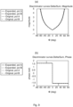
WO2016141961 A1 does not mean that the beam patterns for the individual polarizations have a sum and delta pattern shape, but only that the power patterns when summed over both polarizations have these shapes. This is shown inFig. 8 where the power patterns after applying the expansion technique inWO2016141961 A1 are shown for the individual polarizations as well as the total power from both polarizations for a sum pattern (a) and a delta pattern (b). The discriminator function is thus the same for both polarizations. For example, at Φ = o degrees the curve for polarization A represents the same power relation as the total power curve. - This is further demonstrated in
Fig. 9 , which at (a) shows the amplitude and at (b) the phase of the discriminator function for the individual polarizations as well as for the discriminator function Δ/Σ for the virtual array with two antenna elements having weights [11]T and [1-1]T, respectively, and antenna element separation equal to half of the wavelength, i.e., λ/2. Clearly, the discriminator functions for the individual polarizations are identical to the corresponding discriminator for a sum and delta beam generated from two antenna elements, despite that the constituent complex beam patterns are very different from a sum and delta beam. This is true except for a few points where the discriminator function has discontinuities. These points correspond to angles where the complex beam patterns in one of the polarizations have a null in gain. These discontinuities will have no impact on the angle of arrival estimation since the measurement of only the other polarization can be used at these points. - As disclosed above, beam widths for the two receive
beams Fig. 10 andFig. 11 show complex beam patterns and discriminator functions, respectively, for a case with a 4 antenna element virtual array having weights [1111]T and [11-1-1]T. This corresponds to a beam width which is half of that in the previous example. This could be used to cover a narrower givenangular sector 150 and thus gives higher gain within the givenangular sector 150.Fig. 11 shows that the curves of the discriminator functions are identical to each other. The discriminator function has ambiguities, but these are outside the givenangular sector 150 and will therefore not impact the estimation of the angle of arrival a as part of the beam finding procedure. - In terms of virtual arrays, in some aspects the discriminator function as applied to each of the two receive
beams beams - As disclosed above, in some aspects the radio signal is a beam reference signal received from a transmitting
radio transceiver device 300. Theradio transceiver device 200 could therefore be configured to use the electrical phase relation in order to determine which analog beam(s) to use in subsequent data communication with the transmittingradio transceiver device 300. Particularly, according to an embodiment where the radio signal is received from anotherradio transceiver device 300 theradio transceiver device 200 is configured to perform step S106:
S106: Theradio transceiver device 200 communicates with the so-calledradio transceiver device 300 in a beam, where the beam points in a direction selected according to the electrical phase relation. The beam could be a receive beam and/or a transmit beam. - That is, assuming that the
radio transceiver device 200 is configured to communicate in multiple, narrow, beams, theradio transceiver device 200 could, based on the estimated electrical phase relation, select the beam that is closest to the estimated angle of arrival a for use in subsequent data communication with the transmittingradio transceiver device 300. - Aspects of the radio signal will now be disclosed.
- According to an embodiment each measurement of the radio signal corresponds to either one whole or one half orthogonal frequency-division multiplexing (OFDM) symbol such that one whole or one half OFDM symbol on which a respective one of the measurements is based on received in each of the two receive
beams - In more detail, as disclosed above, using analog beamforming, two sequential measurements could be needed when the two receive
beams beams radio transceiver device 300 to transmit reference signals and for theradio transceiver device 200 to measure on these in two OFDM symbols. It is also possible to perform the two measurements in a single OFDM symbol by first measuring in one receive beam in the first half of an OFDM symbol, then changing the analog phase shifters to generate the other receive beam, and then measuring in the second half of an OFDM symbol in the other receive beam. Hence, in some aspects theradio transceiver device 200 obtains measurements in two consecutive (whole or half) OFDM symbols and uses a first receive beam for a first (whole or half) OFDM symbol and a second receive beam for a second (whole or half) OFDM symbol. - One way to achieve this is for the
radio transceiver device 300 to transmit a beam reference signal (defining the radio signal) that occupies only every second sub-carrier. Transmitting on every other sub-carrier means a zero insertion between every other sample in the frequency domain. By properties of the discrete Fourier transform (DFT), this implies a two-fold periodic repetition of the time domain signal, as illustrated inFig. 12. Fig. 12 schematically illustrates how to generate half OFDM symbols by transmitting on every second sub-carrier. Hence, transmitting on every second sub-carrier means that the resulting OFDM symbol will consist of two identical halves and measurements in the first receive beam can then be performed in the first half and in the second receive beam in the second half (or vice versa). - Transmitting reference signals on every second subcarrier is common practice in Long Term Evolution (LTE) based communications networks where the uplink sounding reference signal (SRS) is transmitted using a so-called comb pattern, where every second or every fourth sub-carrier is occupied by a reference symbol. Therefore, performing the proposed angle of arrival estimation in a single OFDM symbol could be used with SRS-like reference signal structures. Advantages with performing measurements on both receive
beams -
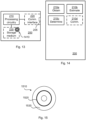
Fig. 13 schematically illustrates, in terms of a number of functional units, the components of aradio transceiver device 200 according to an embodiment.Processing circuitry 210 is provided using any combination of one or more of a suitable central processing unit (CPU), multiprocessor, microcontroller, digital signal processor (DSP), etc., capable of executing software instructions stored in a computer program product 1510 (as inFig. 15 ), e.g. in the form of astorage medium 230. Theprocessing circuitry 210 may further be provided as at least one application specific integrated circuit (ASIC), or field programmable gate array (FPGA). - Particularly, the
processing circuitry 210 is configured to cause theradio transceiver device 200 to perform a set of operations, or steps, S102-S108, as disclosed above. For example, thestorage medium 230 may store the set of operations, and theprocessing circuitry 210 may be configured to retrieve the set of operations from thestorage medium 230 to cause theradio transceiver device 200 to perform the set of operations. The set of operations maybe provided as a set of executable instructions. - Thus the
processing circuitry 210 is thereby arranged to execute methods as herein disclosed. Thestorage medium 230 may also comprise persistent storage, which, for example, can be any single one or combination of magnetic memory, optical memory, solid state memory or even remotely mounted memory. Theradio transceiver device 200 may further comprise acommunications interface 220 at least configured for communications at least with anotherradio transceiver device 300. As such thecommunications interface 220 may comprise one or more transmitters and receivers, comprising analogue and digital components. Theprocessing circuitry 210 controls the general operation of theradio transceiver device 200 e.g. by sending data and control signals to thecommunications interface 220 and thestorage medium 230, by receiving data and reports from thecommunications interface 220, and by retrieving data and instructions from thestorage medium 230. Other components, as well as the related functionality, of theradio transceiver device 200 are omitted in order not to obscure the concepts presented herein. -
Fig. 14 schematically illustrates, in terms of a number of functional modules, the components of aradio transceiver device 200 according to an embodiment. Theradio transceiver device 200 ofFig. 14 comprises a number of functional modules; an obtainmodule 210a configured to perform step S102, anestimate module 210b configured to perform step S104, and a determinemodule 210c configured to perform step S106. Theradio transceiver device 200 ofFig. 14 may further comprise a number of optional functional modules, such as a communicatemodule 210d configured to perform step SS108. In general terms, eachfunctional module 210a-210d may in one embodiment be implemented only in hardware and in another embodiment with the help of software, i.e., the latter embodiment having computer program instructions stored on thestorage medium 230 which when run on the processing circuitry makes theradio transceiver device 200 perform the corresponding steps mentioned above in conjunction withFig 14 . It should also be mentioned that even though the modules correspond to parts of a computer program, they do not need to be separate modules therein, but the way in which they are implemented in software is dependent on the programming language used. Preferably, one or more or allfunctional modules 210a-210d may be implemented by theprocessing circuitry 210, possibly in cooperation with thecommunications interface 220 and/or thestorage medium 230. Theprocessing circuitry 210 may thus be configured to from thestorage medium 230 fetch instructions as provided by afunctional module 210a-210d and to execute these instructions, thereby performing any steps as disclosed herein. - The
radio transceiver device 200 may be provided as a standalone device or as a part of at least one further device. For example, theradio transceiver device 200 may be provided in a node of the radio access network or in a node of the core network. Alternatively, functionality of theradio transceiver device 200 may be distributed between at least two devices, or nodes. These at least two nodes, or devices, may either be part of the same network part (such as the radio access network or the core network) or may be spread between at least two such network parts. - Thus, a first portion of the instructions performed by the
radio transceiver device 200 may be executed in a first device, and a second portion of the of the instructions performed by theradio transceiver device 200 may be executed in a second device; the herein disclosed embodiments are not limited to any particular number of devices on which the instructions performed by theradio transceiver device 200 may be executed. Hence, the methods according to the herein disclosed embodiments are suitable to be performed by aradio transceiver device 200 residing in a cloud computational environment. Therefore, although asingle processing circuitry 210 is illustrated inFig. 13 theprocessing circuitry 210 may be distributed among a plurality of devices, or nodes. The same applies to thefunctional modules 210a-210d ofFig. 14 and thecomputer program 1520 ofFig. 15 (see below). -
Fig. 15 shows one example of acomputer program product 1510 comprising computerreadable storage medium 1530. On this computerreadable storage medium 1530, acomputer program 1520 can be stored, whichcomputer program 1520 can cause theprocessing circuitry 210 and thereto operatively coupled entities and devices, such as thecommunications interface 220 and thestorage medium 230, to execute methods according to embodiments described herein. Thecomputer program 1520 and/orcomputer program product 1510 may thus provide means for performing any steps as herein disclosed. - In the example of
Fig. 15 , thecomputer program product 1510 is illustrated as an optical disc, such as a CD (compact disc) or a DVD (digital versatile disc) or a Blu-Ray disc. Thecomputer program product 1510 could also be embodied as a memory, such as a random access memory (RAM), a read-only memory (ROM), an erasable programmable read-only memory (EPROM), or an electrically erasable programmable read-only memory (EEPROM) and more particularly as a non-volatile storage medium of a device in an external memory such as a USB (Universal Serial Bus) memory or a Flash memory, such as a compact Flash memory. Thus, while thecomputer program 1520 is here schematically shown as a track on the depicted optical disk, thecomputer program 1520 can be stored in any way which is suitable for thecomputer program product 1510. - The inventive concept has mainly been described above with reference to a few embodiments. However, as is readily appreciated by a person skilled in the art, other embodiments than the ones disclosed above are equally possible within the scope of the inventive concept, as defined by the appended patent claims.
Claims (15)
- A method for determining an electrical phase relation between antenna elements (160a, 160b) in an antenna array (190a, 190b), the method being performed by a radio transceiver device (200), the method comprising:obtaining (S102) measurements of the radio signal as received in two receive beams (140a, 140b) covering a given angular sector (150) having a width, wherein the receive beams (140a, 140b) have different complex beam patterns, and wherein the complex beam patterns are generated to be adaptable to the width of the angular sector (150) within which the radio signal is to be received;estimating (S104) the angle of arrival (α) of the radio signal for at least one polarization port of each of the receive beams (140a, 140b) using the measurements in the two receive beams (140a, 140b); anddetermining (S106), from the angle of arrival (α) estimated for each polarization port, an electrical phase relation between antenna elements (160a, 160b) in the antenna array (190a, 190b) that corresponds to the estimated angle of arrival (α), wherein each receive beam (140a, 140b) has two polarization ports, and wherein the two polarization ports of each receive beam (140a, 140b) have mutually different polarizations, and wherein the angle of arrival (α) of the radio signal in each of the two polarization ports represents one intermediate value, and wherein the angle of arrival (α) is estimated using a combination of the intermediate values.
- The method according to claim 1, wherein the angle of arrival (α) of the radio signal for each polarization port is estimated independently of the angle of arrival (α) of any other polarization ports.
- The method according to claim 1, wherein the two receive beams (140a, 140b) are generated such that at any angle within the given angular sector (150) at most one of the receive beam (140a, 140b) has a power gain below a threshold when summed over the two polarization ports of each receive beam (140a, 140b).
- The method according to claim 3, wherein the complex beam patterns are weighted and summed over the two polarization ports when estimating the angle of arrival (α) of the radio signal.
- The method according to claim 1, wherein the receive beams (140a, 140b) are generated using dual-polarization beamforming.
- The method according to claim 5, wherein the dual-polarization beamforming in the antenna array (190a, 190b) is based on a first weight matrix having a first non-zero weight vector for a first of the two polarizations and a second weight matrix having a second non-zero weight vector for a second of the two polarizations,wherein the second weight matrix is based on the weight vectors of the first weight matrix,wherein the first weight matrix is applied to said antenna elements (160a, 160b) to generate a first of the two receive beams (140a, 140b) for a first of the two polarization ports, andwherein the second weight matrix is applied to said antenna elements (160a, 160b) to generate said first of the two receive beams (140a, 140b) for a second of the two polarization ports.
- The method according to claim 5, wherein the dual-polarization beamforming in the antenna array (190a, 190b) is based on generating one or two beam ports, wherein the one or two beam ports are defined by combining at least two non-overlapping virtual arrays of the antenna elements (160a, 160b), wherein the virtual arrays of the two receive beams (140a, 140b) are associated with mutually different weight vectors, wherein a weight vector applied to a virtual array defines a virtual array port,wherein each virtual array has two virtual array ports, the two virtual array ports having identical power patterns and mutually orthogonal polarization, wherein the at least two non-overlapping virtual arrays are combined via expansion weights,wherein the expansion weights map each of the two receive beams (140a, 140b) to the virtual array ports such that each receive beam, when summed over the two polarization ports, has identical power pattern to the virtual array when summed over the two virtual array ports, andwherein at least some of the expansion weights have identical non-zero magnitude and are related in phase to form the two receive beams (140a, 140b).
- The method according to claim 1, wherein estimating the angle of arrival (α) of the radio signal comprises comparing a complex amplitude of the measurements for each of the polarization ports in the two receive beams (140a, 140b) to a discriminator function.
- The method according to claim 8, wherein the discriminator function is based on the complex beam patterns and is, within the given angular sector (150), a one-to-one function of the angle of arrival (α).
- The method according to claims 8 and 9, wherein the discriminator function as applied to each of the two receive beams (140a, 140b) is identical to the discriminator function as applied to virtual array ports corresponding to the two receive beams (140a, 140b).
- The method according to claim 1, wherein the signal is received from another radio transceiver device (300), the method further comprising:
communicating (S108) with said another radio transceiver device (300) in a beam pointing in a direction selected according to the electrical phase relation. - The method according to claim 1, wherein each measurement of the radio signal corresponds to either one whole or one half orthogonal frequency-division multiplexing, OFDM, symbol such that one whole or one half OFDM symbol on which a respective one of the measurements is based on received in each of the two receive beams (140a, 140b).
- A radio transceiver device (200) for determining an electrical phase relation between antenna elements (160a, 160b) in an antenna array (190a, 190b), the radio transceiver device (200) comprising processing circuitry (210), the processing circuitry being configured to cause the radio transceiver device (200) to:obtain measurements of the radio signal as received in two receive beams (140a, 140b) covering a given angular sector (150) having a width, wherein the receive beams (140a, 140b) have different complex beam patterns, and wherein the complex beam patterns are generated to be adaptable to the width of the angular sector (150) within which the radio signal is to be received;estimate the angle of arrival (α) of the radio signal for at least one polarization port of each of the receive beams (140a, 140b) using the measurements in the two receive beams (140a, 140b); anddetermine, from the angle of arrival (α) estimated for each polarization port, an electrical phase relation between antenna elements (160a, 160b) in the antenna array (190a, 190b) that corresponds to the estimated angle of arrival (α), wherein each receive beam (140a, 140b) has two polarization ports, and wherein the two polarization ports of each receive beam (140a, 140b) have mutually different polarizations, and wherein the angle of arrival (α) of the radio signal in each of the two polarization ports represents one intermediate value, and wherein the angle of arrival (α) is estimated using a combination of the intermediate values.
- A computer program (1520) for determining an electrical phase relation between antenna elements (160a, 160b) in an antenna array (190a, 190b), the computer program comprising computer code which, when run on processing circuitry (210) of a radio transceiver device (200), causes the radio transceiver device (200) to:obtain (S102) measurements of the radio signal as received in two receive beams (140a, 140b) covering a given angular sector (150) having a width, wherein the receive beams (140a, 140b) have different complex beam patterns, and wherein the complex beam patterns are generated to be adaptable to the width of the angular sector (150) within which the radio signal is to be received;estimate (S104) the angle of arrival (α) of the radio signal for at least one polarization port of each of the receive beams (140a, 140b) using the measurements in the two receive beams (140a, 140b); anddetermine (S106), from the angle of arrival (α) estimated for each polarization port, an electrical phase relation between antenna elements (160a, 160b) in the antenna array (190a, 190b) that corresponds to the estimated angle of arrival (α), wherein each receive beam (140a, 140b) has two polarization ports, and wherein the two polarization ports of each receive beam (140a, 140b) have mutually different polarizations, and wherein the angle of arrival (α) of the radio signal in each of the two polarization ports represents one intermediate value, and wherein the angle of arrival (α) is estimated using a combination of the intermediate values.
- A computer program product (1510) comprising a computer program (1520) according to claim 14, and a computer readable storage medium (1530) on which the computer program is stored.
Applications Claiming Priority (1)
| Application Number | Priority Date | Filing Date | Title |
|---|---|---|---|
| PCT/EP2017/063459 WO2018219472A1 (en) | 2017-06-02 | 2017-06-02 | Determination of electrical phase relation in a communications network |
Publications (3)
| Publication Number | Publication Date |
|---|---|
| EP3632000A1 EP3632000A1 (en) | 2020-04-08 |
| EP3632000B1 true EP3632000B1 (en) | 2023-08-16 |
| EP3632000C0 EP3632000C0 (en) | 2023-08-16 |
Family
ID=59009690
Family Applications (1)
| Application Number | Title | Priority Date | Filing Date |
|---|---|---|---|
| EP17727875.1A Active EP3632000B1 (en) | 2017-06-02 | 2017-06-02 | Determination of electrical phase relation in a communications network |
Country Status (4)
| Country | Link |
|---|---|
| US (1) | US11411310B2 (en) |
| EP (1) | EP3632000B1 (en) |
| CN (1) | CN110663198B (en) |
| WO (1) | WO2018219472A1 (en) |
Families Citing this family (2)
| Publication number | Priority date | Publication date | Assignee | Title |
|---|---|---|---|---|
| CN111512567B (en) * | 2017-12-20 | 2021-11-30 | 华为技术有限公司 | Apparatus and method for wireless communication with rotating beam management |
| EP3759830A1 (en) * | 2018-02-27 | 2021-01-06 | Telefonaktiebolaget LM Ericsson (publ) | Beam management for a radio transceiver device |
Family Cites Families (53)
| Publication number | Priority date | Publication date | Assignee | Title |
|---|---|---|---|---|
| US3176297A (en) | 1962-11-08 | 1965-03-30 | Sperry Rand Corp | Antenna systems |
| GB1270806A (en) * | 1968-05-31 | 1972-04-19 | Emi Ltd | Improvements relating to aerial arrangements |
| US3824595A (en) | 1971-06-04 | 1974-07-16 | Bunker Ramo | High accuracy direction finding system |
| US4170774A (en) | 1972-01-24 | 1979-10-09 | United Technologies Corporation | Amplitude selected phase interferometer angle measuring radar |
| US3860929A (en) | 1973-05-07 | 1975-01-14 | Texas Instruments Inc | Conformal array antenna/receiver processor system |
| US3969726A (en) * | 1975-02-27 | 1976-07-13 | Texas Instruments Incorporated | Two channel monopulse receiver |
| DE2929254C2 (en) | 1979-07-19 | 1982-05-06 | Siemens AG, 1000 Berlin und 8000 München | Antenna system for direction finding of a microwave signal source |
| FI85427C (en) | 1989-06-14 | 1992-04-10 | Vaisala Oy | Method and apparatus for an object's azimuth and elevation measurement |
| EP0647979B1 (en) | 1993-08-12 | 2002-10-23 | Nortel Networks Limited | Base station antenna arrangement |
| US5541608A (en) | 1995-03-29 | 1996-07-30 | Itt Corporation | Hybrid amplitude/phase comparison direction finding system |
| US5786791A (en) * | 1997-02-24 | 1998-07-28 | Motorola, Inc. | Method for determining an angle of arrival of a signal transmitted by a remote unit in a communication system |
| US6061022A (en) | 1999-06-04 | 2000-05-09 | Itt Manufacturing Enterprises, Inc. | Azimuth and elevation direction finding system based on hybrid amplitude/phase comparison |
| EP1317782B1 (en) | 2000-07-10 | 2006-12-20 | Andrew Corporation | Cellular antenna |
| JP2002151937A (en) | 2000-11-15 | 2002-05-24 | Nec Corp | Adaptive array antenna receiver |
| BR0017138A (en) | 2000-12-23 | 2002-11-19 | Nokia Corp | Base station for a radiocommunication network, base station module for a base station, and method for intensifying angular resolution in estimating uplink signal arrival direction at a base station of a radiocommunication network |
| US6812889B2 (en) | 2002-01-24 | 2004-11-02 | Motorola, Inc. | Methods and apparatus for determining a direction of arrival in a wireless communication system |
| US7042394B2 (en) | 2002-08-14 | 2006-05-09 | Skipper Wireless Inc. | Method and system for determining direction of transmission using multi-facet antenna |
| CN1695271B (en) | 2002-08-21 | 2011-11-09 | 美国博通公司 | Antenna array including virtual antenna elements |
| US6950064B2 (en) | 2002-12-16 | 2005-09-27 | Next-Rf, Inc. | System and method for ascertaining angle of arrival of an electromagnetic signal |
| GB0316402D0 (en) | 2003-07-12 | 2003-08-13 | Qinetiq Ltd | Direction finding |
| US7313403B2 (en) | 2003-08-06 | 2007-12-25 | Hong Kong Applied Science And Technology Research Institute Co., Ltd. | Location positioning in wireless networks |
| US7453946B2 (en) | 2003-09-03 | 2008-11-18 | Intel Corporation | Communication system and method for channel estimation and beamforming using a multi-element array antenna |
| KR100770875B1 (en) * | 2004-05-24 | 2007-10-26 | 삼성전자주식회사 | Beam forming apparatus and method using estimating interference power in array antenna system |
| US6992622B1 (en) * | 2004-10-15 | 2006-01-31 | Interdigital Technology Corporation | Wireless communication method and antenna system for determining direction of arrival information to form a three-dimensional beam used by a transceiver |
| US7242350B1 (en) | 2004-10-20 | 2007-07-10 | Raytheon Company | Estimating an angle-of-arrival of a signal by determining polarization |
| US7342535B2 (en) * | 2005-04-08 | 2008-03-11 | Samsung Electronics Co., Ltd. | Beam-forming apparatus and method using a spatial interpolation based on regular spatial sampling |
| CA2542445A1 (en) * | 2006-04-07 | 2007-10-07 | Tenxc Wireless Inc. | Adaptive multi-beam system |
| US20080303714A1 (en) * | 2007-05-29 | 2008-12-11 | Ezal Kenan O | Compact single-aperture antenna and navigation system |
| US8305265B2 (en) * | 2007-05-29 | 2012-11-06 | Toyon Research Corporation | Radio-based direction-finding navigation system using small antenna |
| US8254487B2 (en) | 2007-08-09 | 2012-08-28 | Samsung Electronics Co., Ltd. | Method and apparatus of codebook-based single-user closed-loop transmit beamforming (SU-CLTB) for OFDM wireless systems |
| FR2938345B1 (en) | 2008-11-07 | 2010-12-31 | Thales Sa | METHOD FOR DETERMINING THE ARRIVAL DIRECTION OF AN ELECTROMAGNETIC WAVE |
| WO2010139840A1 (en) * | 2009-06-03 | 2010-12-09 | Elektrobit System Test Oy | Over-the-air test |
| GB2471669B (en) * | 2009-07-06 | 2012-04-04 | Socowave Technologies Ltd | Wireless network element and method for antenna array control |
| US9545222B2 (en) * | 2009-09-01 | 2017-01-17 | Adidas Ag | Garment with noninvasive method and system for monitoring physiological characteristics and athletic performance |
| BR112012009896A2 (en) * | 2009-10-28 | 2016-11-29 | Ericsson Telefon Ab L M | method to generate two beams, and antenna configured to generate two beams |
| US8558735B2 (en) * | 2010-08-20 | 2013-10-15 | Lockheed Martin Corporation | High-resolution radar map for multi-function phased array radar |
| US20130286960A1 (en) | 2012-04-30 | 2013-10-31 | Samsung Electronics Co., Ltd | Apparatus and method for control channel beam management in a wireless system with a large number of antennas |
| US9924381B2 (en) * | 2012-08-13 | 2018-03-20 | Telefonaktiebolaget Lm Ericsson (Publ) | Enhancing uplink measurements for positioning by adaptively using multi-antenna systems |
| TWI457585B (en) | 2012-12-11 | 2014-10-21 | Univ Nat Chiao Tung | Method and device for direction-of-arrival estimation |
| CN104010361B (en) | 2013-02-22 | 2018-04-10 | 中兴通讯股份有限公司 | Alignment system and method |
| WO2014190074A1 (en) * | 2013-05-22 | 2014-11-27 | New York University | System and method for estimating direction of arrival of a signal incident on an antenna array |
| US9680234B2 (en) * | 2013-08-28 | 2017-06-13 | Harris Corporation | Dual polarization ground-based phased array antenna system for aircraft communications and associated methods |
| US9544036B2 (en) * | 2014-05-08 | 2017-01-10 | Telefonaktiebolaget Lm Ericsson (Publ) | Beam forming for reference signals using an antenna arrangement |
| US9819081B2 (en) * | 2014-07-07 | 2017-11-14 | Qatar Foundation For Education, Science And Comminity Development | Reconfigurable radio direction finder system and method |
| US10320461B2 (en) * | 2014-07-08 | 2019-06-11 | New York University | System, method and computer-readable medium for estimating direction of arrival of a signal incident on at least one antenna array |
| US9398468B1 (en) * | 2014-12-29 | 2016-07-19 | Huawei Technologies Co., Ltd. | Cellular array with steerable spotlight beams |
| EP3266119B1 (en) * | 2015-03-06 | 2018-06-27 | Telefonaktiebolaget LM Ericsson (publ) | Beam forming using an antenna arrangement |
| US20160268681A1 (en) * | 2015-03-10 | 2016-09-15 | Board Of Trustees Of Michigan State University | Three-Element Antenna Array for Wireless Handsets |
| WO2016184214A1 (en) | 2015-05-20 | 2016-11-24 | Mediatek Inc. | Methods for efficient beam training and communications apparatus and network control device utilizing the same |
| US10705176B2 (en) | 2015-10-13 | 2020-07-07 | Northrop Grumman Systems Corporation | Signal direction processing for an antenna array |
| US10554279B2 (en) * | 2016-02-25 | 2020-02-04 | Apple Inc. | Device and method for synchronous beam switching |
| US20180038934A1 (en) | 2016-08-03 | 2018-02-08 | Sr Technologies, Inc. | Discrimination of signal angle of arrival using at least two antennas |
| US11139873B2 (en) * | 2017-05-24 | 2021-10-05 | Telefonaktiebolaget Lm Ericsson (Publ) | Beam width adjustment |
-
2017
- 2017-06-02 CN CN201780091518.2A patent/CN110663198B/en active Active
- 2017-06-02 US US15/540,640 patent/US11411310B2/en active Active
- 2017-06-02 EP EP17727875.1A patent/EP3632000B1/en active Active
- 2017-06-02 WO PCT/EP2017/063459 patent/WO2018219472A1/en active Application Filing
Also Published As
| Publication number | Publication date |
|---|---|
| CN110663198A (en) | 2020-01-07 |
| WO2018219472A1 (en) | 2018-12-06 |
| CN110663198B (en) | 2024-03-08 |
| US11411310B2 (en) | 2022-08-09 |
| EP3632000A1 (en) | 2020-04-08 |
| US20180358695A1 (en) | 2018-12-13 |
| EP3632000C0 (en) | 2023-08-16 |
Similar Documents
| Publication | Publication Date | Title |
|---|---|---|
| US11444707B2 (en) | Angle of arrival estimation in a radio communications network | |
| CN106464332B (en) | Beamforming using an antenna arrangement | |
| US11550017B2 (en) | Angle of arrival estimation in a radio communications network | |
| EP3381133B1 (en) | Antenna system configuration | |
| US11271696B2 (en) | Beam management of a radio transceiver device | |
| US11070268B2 (en) | Wireless communication node adapted to radiate antenna beams of different types | |
| US10382110B2 (en) | Adaptive user-specific beam forming | |
| EP3732796B1 (en) | Beam management of a radio transceiver device | |
| EP3632000B1 (en) | Determination of electrical phase relation in a communications network | |
| CN111316571A (en) | Efficient beam search | |
| WO2019068305A1 (en) | Receiving device and methods thereof | |
| EP3360265B1 (en) | Channel condition estimation | |
| WO2019001692A1 (en) | Determination of complex weight vectors for a radio transceiver device | |
| WO2021043399A1 (en) | Beamformed transmission towards a radio transceiver device | |
| EP4302417A1 (en) | Transmission of reference signal resources |
Legal Events
| Date | Code | Title | Description |
|---|---|---|---|
| STAA | Information on the status of an ep patent application or granted ep patent |
Free format text: STATUS: UNKNOWN |
|
| STAA | Information on the status of an ep patent application or granted ep patent |
Free format text: STATUS: THE INTERNATIONAL PUBLICATION HAS BEEN MADE |
|
| PUAI | Public reference made under article 153(3) epc to a published international application that has entered the european phase |
Free format text: ORIGINAL CODE: 0009012 |
|
| STAA | Information on the status of an ep patent application or granted ep patent |
Free format text: STATUS: REQUEST FOR EXAMINATION WAS MADE |
|
| 17P | Request for examination filed |
Effective date: 20191216 |
|
| AK | Designated contracting states |
Kind code of ref document: A1 Designated state(s): AL AT BE BG CH CY CZ DE DK EE ES FI FR GB GR HR HU IE IS IT LI LT LU LV MC MK MT NL NO PL PT RO RS SE SI SK SM TR |
|
| AX | Request for extension of the european patent |
Extension state: BA ME |
|
| DAV | Request for validation of the european patent (deleted) | ||
| DAX | Request for extension of the european patent (deleted) | ||
| STAA | Information on the status of an ep patent application or granted ep patent |
Free format text: STATUS: EXAMINATION IS IN PROGRESS |
|
| STAA | Information on the status of an ep patent application or granted ep patent |
Free format text: STATUS: EXAMINATION IS IN PROGRESS |
|
| 17Q | First examination report despatched |
Effective date: 20200922 |
|
| STAA | Information on the status of an ep patent application or granted ep patent |
Free format text: STATUS: EXAMINATION IS IN PROGRESS |
|
| GRAP | Despatch of communication of intention to grant a patent |
Free format text: ORIGINAL CODE: EPIDOSNIGR1 |
|
| STAA | Information on the status of an ep patent application or granted ep patent |
Free format text: STATUS: GRANT OF PATENT IS INTENDED |
|
| INTG | Intention to grant announced |
Effective date: 20230323 |
|
| GRAS | Grant fee paid |
Free format text: ORIGINAL CODE: EPIDOSNIGR3 |
|
| GRAA | (expected) grant |
Free format text: ORIGINAL CODE: 0009210 |
|
| STAA | Information on the status of an ep patent application or granted ep patent |
Free format text: STATUS: THE PATENT HAS BEEN GRANTED |
|
| AK | Designated contracting states |
Kind code of ref document: B1 Designated state(s): AL AT BE BG CH CY CZ DE DK EE ES FI FR GB GR HR HU IE IS IT LI LT LU LV MC MK MT NL NO PL PT RO RS SE SI SK SM TR |
|
| REG | Reference to a national code |
Ref country code: GB Ref legal event code: FG4D |
|
| REG | Reference to a national code |
Ref country code: CH Ref legal event code: EP |
|
| REG | Reference to a national code |
Ref country code: DE Ref legal event code: R096 Ref document number: 602017072766 Country of ref document: DE |
|
| GRAT | Correction requested after decision to grant or after decision to maintain patent in amended form |
Free format text: ORIGINAL CODE: EPIDOSNCDEC |
|
| REG | Reference to a national code |
Ref country code: IE Ref legal event code: FG4D |
|
| U01 | Request for unitary effect filed |
Effective date: 20230831 |
|
| RAP4 | Party data changed (patent owner data changed or rights of a patent transferred) |
Owner name: TELEFONAKTIEBOLAGET LM ERICSSON (PUBL) |
|
| U07 | Unitary effect registered |
Designated state(s): AT BE BG DE DK EE FI FR IT LT LU LV MT NL PT SE SI Effective date: 20230912 |
|
| PG25 | Lapsed in a contracting state [announced via postgrant information from national office to epo] |
Ref country code: GR Free format text: LAPSE BECAUSE OF FAILURE TO SUBMIT A TRANSLATION OF THE DESCRIPTION OR TO PAY THE FEE WITHIN THE PRESCRIBED TIME-LIMIT Effective date: 20231117 |
|
| PG25 | Lapsed in a contracting state [announced via postgrant information from national office to epo] |
Ref country code: IS Free format text: LAPSE BECAUSE OF FAILURE TO SUBMIT A TRANSLATION OF THE DESCRIPTION OR TO PAY THE FEE WITHIN THE PRESCRIBED TIME-LIMIT Effective date: 20231216 |
|
| PG25 | Lapsed in a contracting state [announced via postgrant information from national office to epo] |
Ref country code: RS Free format text: LAPSE BECAUSE OF FAILURE TO SUBMIT A TRANSLATION OF THE DESCRIPTION OR TO PAY THE FEE WITHIN THE PRESCRIBED TIME-LIMIT Effective date: 20230816 Ref country code: NO Free format text: LAPSE BECAUSE OF FAILURE TO SUBMIT A TRANSLATION OF THE DESCRIPTION OR TO PAY THE FEE WITHIN THE PRESCRIBED TIME-LIMIT Effective date: 20231116 Ref country code: IS Free format text: LAPSE BECAUSE OF FAILURE TO SUBMIT A TRANSLATION OF THE DESCRIPTION OR TO PAY THE FEE WITHIN THE PRESCRIBED TIME-LIMIT Effective date: 20231216 Ref country code: HR Free format text: LAPSE BECAUSE OF FAILURE TO SUBMIT A TRANSLATION OF THE DESCRIPTION OR TO PAY THE FEE WITHIN THE PRESCRIBED TIME-LIMIT Effective date: 20230816 Ref country code: GR Free format text: LAPSE BECAUSE OF FAILURE TO SUBMIT A TRANSLATION OF THE DESCRIPTION OR TO PAY THE FEE WITHIN THE PRESCRIBED TIME-LIMIT Effective date: 20231117 |
|
| PG25 | Lapsed in a contracting state [announced via postgrant information from national office to epo] |
Ref country code: PL Free format text: LAPSE BECAUSE OF FAILURE TO SUBMIT A TRANSLATION OF THE DESCRIPTION OR TO PAY THE FEE WITHIN THE PRESCRIBED TIME-LIMIT Effective date: 20230816 |