EP3631094B1 - Geotextil - Google Patents
Geotextil Download PDFInfo
- Publication number
- EP3631094B1 EP3631094B1 EP17728477.5A EP17728477A EP3631094B1 EP 3631094 B1 EP3631094 B1 EP 3631094B1 EP 17728477 A EP17728477 A EP 17728477A EP 3631094 B1 EP3631094 B1 EP 3631094B1
- Authority
- EP
- European Patent Office
- Prior art keywords
- reactant
- bacteria
- flow network
- geosynthetic
- geosynthetic element
- Prior art date
- Legal status (The legal status is an assumption and is not a legal conclusion. Google has not performed a legal analysis and makes no representation as to the accuracy of the status listed.)
- Active
Links
Images


Classifications
-
- E—FIXED CONSTRUCTIONS
- E02—HYDRAULIC ENGINEERING; FOUNDATIONS; SOIL SHIFTING
- E02D—FOUNDATIONS; EXCAVATIONS; EMBANKMENTS; UNDERGROUND OR UNDERWATER STRUCTURES
- E02D17/00—Excavations; Bordering of excavations; Making embankments
- E02D17/20—Securing of slopes or inclines
- E02D17/202—Securing of slopes or inclines with flexible securing means
-
- E—FIXED CONSTRUCTIONS
- E02—HYDRAULIC ENGINEERING; FOUNDATIONS; SOIL SHIFTING
- E02B—HYDRAULIC ENGINEERING
- E02B3/00—Engineering works in connection with control or use of streams, rivers, coasts, or other marine sites; Sealings or joints for engineering works in general
- E02B3/04—Structures or apparatus for, or methods of, protecting banks, coasts, or harbours
- E02B3/12—Revetment of banks, dams, watercourses, or the like, e.g. the sea-floor
- E02B3/122—Flexible prefabricated covering elements, e.g. mats, strips
-
- E—FIXED CONSTRUCTIONS
- E02—HYDRAULIC ENGINEERING; FOUNDATIONS; SOIL SHIFTING
- E02D—FOUNDATIONS; EXCAVATIONS; EMBANKMENTS; UNDERGROUND OR UNDERWATER STRUCTURES
- E02D3/00—Improving or preserving soil or rock, e.g. preserving permafrost soil
- E02D3/12—Consolidating by placing solidifying or pore-filling substances in the soil
-
- A—HUMAN NECESSITIES
- A01—AGRICULTURE; FORESTRY; ANIMAL HUSBANDRY; HUNTING; TRAPPING; FISHING
- A01G—HORTICULTURE; CULTIVATION OF VEGETABLES, FLOWERS, RICE, FRUIT, VINES, HOPS OR SEAWEED; FORESTRY; WATERING
- A01G24/00—Growth substrates; Culture media; Apparatus or methods therefor
- A01G24/40—Growth substrates; Culture media; Apparatus or methods therefor characterised by their structure
- A01G24/44—Growth substrates; Culture media; Apparatus or methods therefor characterised by their structure in block, mat or sheet form
-
- B—PERFORMING OPERATIONS; TRANSPORTING
- B32—LAYERED PRODUCTS
- B32B—LAYERED PRODUCTS, i.e. PRODUCTS BUILT-UP OF STRATA OF FLAT OR NON-FLAT, e.g. CELLULAR OR HONEYCOMB, FORM
- B32B5/00—Layered products characterised by the non- homogeneity or physical structure, i.e. comprising a fibrous, filamentary, particulate or foam layer; Layered products characterised by having a layer differing constitutionally or physically in different parts
- B32B5/22—Layered products characterised by the non- homogeneity or physical structure, i.e. comprising a fibrous, filamentary, particulate or foam layer; Layered products characterised by having a layer differing constitutionally or physically in different parts characterised by the presence of two or more layers which are next to each other and are fibrous, filamentary, formed of particles or foamed
- B32B5/24—Layered products characterised by the non- homogeneity or physical structure, i.e. comprising a fibrous, filamentary, particulate or foam layer; Layered products characterised by having a layer differing constitutionally or physically in different parts characterised by the presence of two or more layers which are next to each other and are fibrous, filamentary, formed of particles or foamed one layer being a fibrous or filamentary layer
- B32B5/26—Layered products characterised by the non- homogeneity or physical structure, i.e. comprising a fibrous, filamentary, particulate or foam layer; Layered products characterised by having a layer differing constitutionally or physically in different parts characterised by the presence of two or more layers which are next to each other and are fibrous, filamentary, formed of particles or foamed one layer being a fibrous or filamentary layer another layer next to it also being fibrous or filamentary
-
- D—TEXTILES; PAPER
- D10—INDEXING SCHEME ASSOCIATED WITH SUBLASSES OF SECTION D, RELATING TO TEXTILES
- D10B—INDEXING SCHEME ASSOCIATED WITH SUBLASSES OF SECTION D, RELATING TO TEXTILES
- D10B2505/00—Industrial
- D10B2505/20—Industrial for civil engineering, e.g. geotextiles
- D10B2505/204—Geotextiles
-
- E—FIXED CONSTRUCTIONS
- E02—HYDRAULIC ENGINEERING; FOUNDATIONS; SOIL SHIFTING
- E02D—FOUNDATIONS; EXCAVATIONS; EMBANKMENTS; UNDERGROUND OR UNDERWATER STRUCTURES
- E02D17/00—Excavations; Bordering of excavations; Making embankments
- E02D17/18—Making embankments, e.g. dikes, dams
-
- E—FIXED CONSTRUCTIONS
- E02—HYDRAULIC ENGINEERING; FOUNDATIONS; SOIL SHIFTING
- E02D—FOUNDATIONS; EXCAVATIONS; EMBANKMENTS; UNDERGROUND OR UNDERWATER STRUCTURES
- E02D2300/00—Materials
- E02D2300/0084—Geogrids
Definitions
- the present invention relates to a geosynthetic element for geotechnical engineering applications. More specifically, the geosynthetic element according to the present invention comprises bacteria carriers for calcifying bacteria and a flow network. The present invention also relates to a method of inducing microbial calcium carbonate precipitation in a geomaterial by using the geosynthetic element.
- Geosynthetic materials are generally composed of polypropylene or other polymeric substances and aim to stabilise soil formations for the construction of embankments and for the protection of slopes or riverbanks against erosion. Eight main product categories are identified: geotextiles, geogrids, geonets, geomembranes, geosynthetic clay liners, geofoams, geocells and geocomposites, all targeting various applications and used with various installation methods.
- Microbiologically induced calcium carbonate precipitation is a known reactive mechanism that results in the formation and growth of calcium carbonate (CaCOs) particles (also referred to as microbe cement) within the soil matrix.
- MICP may be used for improving soil stability and its mechanical properties.
- ureolytic calcifying bacteria have been directly introduced into the soil or other geological formations.
- Applications of MICP via infiltration, via systems of pumping and extraction wells, or via direct mixing with aggregates are known for consolidating soils. It is also known to use MICP for the production of masonry, for dust control and for the manufacture of some construction materials.
- MICP is a natural process based on microbial-induced urea hydrolysis (Equation 1).
- FR2873725 and FR2911887 disclose the use of a family of calcifying bacteria, and that of denitrifying bacteria for increasing the resistance of porous materials.
- a method is described for applying MICP by directly feeding soils with calcifying bacteria and reactant solutions.
- FR2985746 also introduces recirculation of water throughout the different steps of the MICP process, as a means of economising resources and further reducing installation costs.
- direct feeding of soils with bacteria via a single injection well is not always an optimal solution, because it leads to limited calcium carbonate precipitation in the vicinity of the injection source and poor propagation of the calcifying bacteria in the surrounding geomaterial.
- heavy feeding equipment and time-consuming repetitions of injections are required to improve larger soil volumes.
- the present invention aims to overcome at least some of the problems identified above related to the use of the MICP in geotechnical engineering applications.
- a geosynthetic element for a geotechnical engineering application as recited in claim 1.
- the present invention describes new geosynthetic elements and their application methods for the implementation of MICP as a means of improving the stability and/or mechanical properties of geomaterials, such as various types of soil, sand, gravel and rock, or their formations in subterranean works.
- the proposed new geosynthetic elements may comprise prefabricated composite lattice layers, fibre systems, prefabricated drains etc, arranged to carry calcifying bacterial cells, such as Sporosarcina Pasteurii.
- the application of the MICP process by using the proposed new geosynthetic elements or products provides an alternative to the direct introduction (via infiltration, via systems of pumping and extraction wells, or via direct mixing with aggregates) of ureolytic, calcifying bacteria into soils or other geological formations.
- the application of the MICP process by using the proposed geosynthetic elements aims, for example, to increase the load-bearing capacity of geomaterials, stabilise slopes, consolidate geomaterials, restore weak foundations, protect soils against erosion and/or improve their resistance against liquefaction.
- FIGS 1 and 2 schematically illustrate a geosynthetic element 1 according to the first embodiment of the present invention.
- Figure 1 is a schematic perspective view
- Figure 2 is a partial cross-sectional view taken along the line A-A of Figure 1 but not showing the cross-section along the whole length of the line A-A.
- the geosynthetic element 1 is a geomembrane 1, which when folded forms a roll, and when unfolded forms a mat-type substantially flat element which can be emplaced either horizontally or on inclined planes.
- the geomembrane 1 in this example comprises a set of hollow capsules, cavities or carriers 3 for receiving or accommodating calcifying bacterial cells, referred to simply as bacteria, in various forms as explained later.
- the capsules 3 are arranged in multiple, substantially parallel rows to form a carrier network for the bacteria.
- the capsules 3 are arranged to protrude from an otherwise flat first surface 5 of the membrane 1, referred to as a top surface.
- the capsules 3 protrude only form the top surface 5 of the membrane but in another solution, they could protrude also from a second surface 7, referred to as a bottom surface, in this manner fully traversing the cross-sectional width of the membrane 1.
- the capsules 3 may be permeable, biodegradable or soluble (water-soluble) or comprise a sieve to allow the bacteria to be dispersed to the surrounding environment.
- the capsules 3 are designed for the emplacement of lyophilized (freeze-dried) bacterial cells, bacterial spores or vegetative bacterial cells (in liquid medium). If the capsules comprise a sieve or another similar element, then the capsules 3 may be made of the same composite plastic material as the remaining membrane.
- the bacterial cells comprising the urease enzyme, are encapsulated in predetermined positions in the geosynthetic carrier network.
- encapsulation takes place in two steps as explained below:
- the membrane 1 also comprises a reactant circulation network or a flow network for circulating a reactant solution or medium, referred to simply as a reactant, and optionally additional bacteria depending on the adopted MICP strategy.
- the circulation network can be embedded in the membrane as shown in Figure 2 or it could be placed for instance on the top and/or bottom surface 5, 7 of the membrane.
- the circulation network runs substantially parallel with the top and bottom surfaces 5, 7, and between them.
- the circulation network is connected to the capsules 3 through openings in the circulation network in such a manner that the reactant and, optionally, the additional bacteria escape the circulation network to the surrounding environment through the capsules 3.
- the circulation network may comprise conduits or tubes 9.
- the largest cross-sectional dimension e.g. diameter if the cross-section is of circular shape
- the largest cross-sectional dimension may be between 1cm and 0.1mm. However, in certain applications the largest cross-sectional dimension may be larger, for example up to 10cm.
- the membrane further comprises a set of inlets 11 and a set of outlets 13 for the circulation network.
- a set of inlets 11 In the example of Figure 1 , only one inlet 11 is shown and three outlets 13.
- the reactant and optionally the additional bacteria are introduced into the circulation network through the set of inlets 11, while at least a portion of the reactant is arranged to exit the circulation network through the set of outlets 13 to be reused if necessary.
- the set of inlets 11 are at first endpoints of the circulation network, while the set of outlets 13 are at second, different endpoints of the circulation network.
- the circulation network may be partially or substantially fully filled with the reactant prior to, or after having placed the membrane into or onto the geomaterial.
- Circulation of the reactant solutions in the embedded flow network results in the diffusion of the cells from the capsules 3 to the surrounding geomaterial. Based on the design of the MICP process, it is possible to further supply the circulation network with additional volumes of reactant media including vegetative calcifying cells.
- the reactant may comprise combinations of dissolved urea and/or dissolved calcium in water, or other elements, such as ammonium chloride.
- the reactant may include equimolar concentrations of calcium chloride and urea.
- the circulation network may be filled with the reactant by a continuous flow through the circulation network. Alternatively, circulation of reactants occurs via batch flows of fixed or varying time intervals through the circulation network.
- reactant flow directions are different between consecutive neighbouring layers of membranes 1 or between consecutive rows of tubes 9 within one single layer. Furthermore, it is possible to select and dynamically vary the number of active inlets and/or outputs. The exact flow regime applied through the embedded network is to be chosen based on the desired MICP strategy. It is to be noted that the above description about the reactant solution and its flow configuration also applies to the embodiments explained below.
- FIG. 3 schematically illustrates the second embodiment of the present invention.
- the geosynthetic element 1 is a geogrid or lattice, which can be rolled and unrolled similar to the membrane of the first embodiment.
- the geogrid 1 comprises a set of rods 15 or tubes, which in this example are arranged substantially parallel to each other.
- the rods 15 may be plastic composites, and all or only some of them are hollow to carry the bacteria and to allow the reactant to pass through the rods 15. In other words, the rods 15 are arranged to receive both the bacteria and the reactant.
- the rods also provide additional structural integrity to soils. Some of the rods 15 may be solid and non-hollow to increase the strength of the geogrid 1.
- a first end of the rod 15 may form the inlet 11, while a second end of the rod 15 may form the outlet 13.
- the rods 15 comprise openings, holes, orifices, cuts or slits 17 on their surface to allow for the diffusion of the bacterial cells and reactant solution to the surrounding environment.
- the openings 17 may be distributed around the periphery of the rods evenly or unevenly and lengthwise along the rods 15 (the circulation network). The size and/or location of the openings depend(s) again on the chosen manner for applying the MICP process and/or on the environment.
- the rods 15 are connected to each other with connecting elements 19, which in this example are metallic or plastic fibres. These fibres further increase the strength and stability of the composite geogrid 1.
- FIG 4 schematically shows the geogrid 1 when used for a construction of an embankment.
- the geogrid 1 together with the applied MICP process mitigate liquefaction risk, for example.
- Embankments are constructed in soil layers 21 with geosynthetic elements often placed between them for increasing their overall stability.
- the geogrids 1 of Figure 3 may be placed in multiple horizontal layers with their vertical spacing determined according to the design. For simplicity, only one geogrid layer is shown in Figure 4 .
- the width of the geogrid 1 exceeds the width of the embankment in order to allow the geogrid tip to fold upwards following the slope of the embankment and then backwards to entrap soil for increased stability.
- the MICP process is applied by using the network of hollow rods 15 incorporated in the geogrid 1.
- Embankments are typically built in transportation works (roads, railways etc) and are susceptible to liquefaction hazard in seismic zones.
- Application of the MICP results in the nucleation and growth of microbe cement particles, which endow soil with the necessary cohesion to prevent liquefaction.
- the main advantage of the proposed design method is that the network of rods or tubes 15 can be activated in multiple, alternative ways during or after the construction of the embankment (should rehabilitation works be needed).
- individual rods 15 of the same geogrid layer can be used alternatively as injection and extraction tubes for the reactant.
- a given individual geogrid layer can be used as an injection source, while the ones above and below it act as extraction sources, and vice versa.
- this design method offers flexibility in the application of MICP and ensures homogeneity of precipitated microbe cement.
- FIGs 5a and 5b illustrate a geosynthetic element 1 according to the third embodiment of the present invention.
- the geosynthetic element 1 is a system of expandable or extensible microfibres.
- the system comprises a set of plastic microfibres 19 placed between a first plate or cap 23 and a second plate or cap 25 in an extended state of the system as shown in Figure 5b . These two plates 23, 25 can be separated from each other.
- Figure 5a shows the system in a closed or retracted state
- Figure 5b shows the system in an open or extended state.
- the system comprises expandable microfibres 19, which may be coated in bacterial resin for the application of the MICP via drilling as explained later.
- the coating may be a dissolvable bacterial resin coating, such as hydrogel resin.
- the coating would comprise lyophilised (freeze-dried) bacterial cells, which once the coating has been dissolved, could come in contact with the reactant.
- the microfibres 19 not only provide additional integrity to the geomaterial but ensure that: (i) the bacterial cells are distributed along the drilling path and (ii) enough airspace is generated during drilling for applying the MICP process to soils with increased content in fines.
- the system further comprises a network of microtubes 9 for receiving the reactant solution and optionally the bacteria to allow the drilling bore to be filled with the reactant solution.
- microfibre rings 27 may be provided to add additional integrity to the system.
- the first and second end plates 23, 25 are hollow to accommodate the fibres 19, the tubes 9 and the rings 27 in the closed state of the system.
- the first and/or second plates 23, 25 may also receive a solution rich in vegetative bacteria so that the fibres 19, the tubes 9 and/or the rings 27 can be impregnated in calcifying bacteria. When these elements unfold, they would still keep at least some of the bacteria on their surfaces and when these bacteria come in contact with the reactant, the microbe cement is formed.
- FIGs 6a to 6d illustrate the process of applying the system of expandable plastic microfibres 1 into the soil via drilling and down to top unfolding of the system for inducing the MICP at targeted depths.
- Drilling in this example is carried out by an auger 29, which has a modified tip to incorporate the separable plates 23, 25. The two plates 23, 25 are protected at the auger's tip.
- the auger 29 moves upwards ( Figures 6b and 6c ) and a fixing rod 31 extends or stretches out in order to keep the first plate (bottom plate) 23 fixed at the desired depth, while the second plate (upper plate) 25 moves upwards following the auger's tip.
- the rod 31 used for fixing the bottom 23 may comprise a conduit for the circulation of the reactant solution for inducing the MICP in the vicinity of the microfibres 19.
- the conduit and the rod 31 comprise openings on their surfaces to allow the reactant to escape the conduit and the rod 31.
- the microtubes 19 may also be used for circulating and spreading the reactant solution.
- the advantage of this kind of application is that the bacterial cells can be placed into the soil during drilling (by e.g. having the resin coating on the fibres 19 and/or by the impregnation approach) and their presence ensures precipitation of microbe cement along the drilling path. Furthermore, air space is generated during the drilling and installation of the microfibre system 1. This allows extending the application of the MICP to soils with increased content of fines.
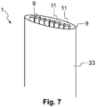
- FIG. 7 illustrates the geosynthetic element 1 according to the fourth embodiment of the present invention.
- the geosynthetic element 1 is a prefabricated drain that can be placed in the geomaterial.
- FIG 7 only one end of the drain 1 is shown. These drains 1 may be many metres long. A given number of drains are typically placed substantially vertically within a given area, where the number depends for example on the soil composition.
- the drain 1 comprises a set of microtubes 9 surrounded by an outer cloth 33 or sleeve, which in this example is permeable.
- the microtubes have a rectangular cross-section. However, other shapes, such as circular, would be equally possible.
- Water or other reactant media are arranged to run through the set of microtubes 9 and/or the outer cloth 33 to lead the water from the surface into a subterranean soil formation.
- the microtubes 9 are arranged to receive and hold the calcifying bacteria, and they are also used to circulate the reactant solution. Openings on their periphery make it possible to diffuse the bacteria and the reactant solution to the surrounding environment. Thus, the microtubes 9 form the encapsulation carriers and subsequently the reactant circulation network.
- the drain 1 may also comprise solid rods (which may or may not be hollow) running for example next to the tubes 9 to increase the strength of the drain 1.
- Figures 1 to 4 illustrate new designs of the composite layers of the geosynthetic element 1 with the provision of embedded circulation networks and that of predetermined positions for bacterial encapsulation for direct application to geomaterials.
- Figures 5a and 5b show a new design of the system of expandable microfibres 1, while Figure 7 illustrates a new design for the prefabricated drain 1.
- the geosynthetic elements 1 comprise the bacteria (at least before circulating the reactant) and the circulation network in addition to some (other) structural elements.
- the advantage of such designs is the incorporation of the circulation networks and the capsules 3 or carriers of the calcifying cells in predetermined positions. This ensures homogenous distribution of calcifying biomass upon emplacement at the installation site.
- the bacterial cells do not have to travel long distances from a fixed injection source since their position is predetermined as a result of the encapsulation for example in the composite body.
- the capsules 3 may be soluble or biodegradable or made of the same composite material as the remaining geosynthetic element 1 but comprising a sieve, for example, to allow homogenous spreading of the bacterial cells to the surrounding environment.
- the network of the microtubes 9 or the rods 15 is used for directly applying the MICP, targeting increased adhesion between the composite layers and geomaterials and increased overall strength and stiffness of the surrounding volume.
- Another advantage of the invention is that the proposed geosynthetic elements 1 are lightweight, and can be easily transported and unrolled or unfolded at the installation site.
- a further variant of the present invention may be easily obtained e.g. from the first embodiment by removing the continuous bottom and top surfaces.
- the circulation network would be directly exposed to the surrounding geomaterial.
- the manner of arranging the circulation network e.g. how close the tubes of the circulation network run to each other and at which angle
- the resulting matrix could look like a combination of interconnected triangles (or rectangles or other shapes), where the triangle edges would be formed by the tubes of the circulation network, and the area inside the triangle edges would be empty or occupied by the geomaterial once the matrix has been installed.
Landscapes
- Engineering & Computer Science (AREA)
- General Engineering & Computer Science (AREA)
- Structural Engineering (AREA)
- Mining & Mineral Resources (AREA)
- Life Sciences & Earth Sciences (AREA)
- Civil Engineering (AREA)
- General Life Sciences & Earth Sciences (AREA)
- Paleontology (AREA)
- Environmental & Geological Engineering (AREA)
- Mechanical Engineering (AREA)
- Ocean & Marine Engineering (AREA)
- Agronomy & Crop Science (AREA)
- Soil Sciences (AREA)
- Environmental Sciences (AREA)
- Micro-Organisms Or Cultivation Processes Thereof (AREA)
- Pit Excavations, Shoring, Fill Or Stabilisation Of Slopes (AREA)
- Apparatus Associated With Microorganisms And Enzymes (AREA)
Claims (15)
- Geosynthetisches Element (1) für eine geotechnische Anwendung, wobei das geosynthetische Element (1) dadurch gekennzeichnet ist, dass es umfasst:• Bakterienträger (3, 15, 19), die Bakterien tragen, wobei die Bakterien so beschaffen sind, dass sie eine feste Kalziumkarbonatausfällung induzieren, und angeordnet sind, um sich von den Bakterienträgern (3, 15, 19) auf ein umgebendes Geomaterial auszubreiten; und• ein Strömungsnetz, umfassend Öffnungen (17) auf seiner Oberfläche, um es einem Reaktanten zu ermöglichen, sich von dem Strömungsnetz in das umgebende Geomaterial entlang des Strömungsnetzes auszubreiten, um festes Kalziumkarbonat zu erzeugen, wobei das Strömungsnetz ferner einen Satz von Einlässen (11) zum Einspeisen des Reaktanten in das Strömungsnetz und einen Satz von Auslässen (13) zum Abführen mindestens eines Teils des Reaktanten aus dem Strömungsnetz umfasst.
- Geosynthetisches Element (1) nach Anspruch 1, wobei das geosynthetische Element (1) mindestens eines der folgenden Elemente umfasst: eine Membran, ein Gitter, einen Abfluss und ein System aus dehnbaren Rohren.
- Geosynthetisches Element (1) nach Anspruch 2, wobei die Membran eine aufrollbare, nicht durchlöcherte Matte ist.
- Geosynthetisches Element (1) nach einem der vorhergehenden Ansprüche, wobei die Bakterienträger (3, 15, 19) Hohlräume (3) zur Aufnahme der Bakterien umfassen, und wobei die Hohlräume (3) mit dem Strömungsnetz verbunden sind.
- Geosynthetisches Element (1) nach Anspruch 4, wobei die Hohlräume (3) eine biologisch abbaubare Schicht, ein siebähnliches Element, eine lösliche Membran oder eine Kombination davon umfassen, um den Bakterien und dem Reaktanten zu ermöglichen, aus den Hohlräumen (3) zu entweichen.
- Geosynthetisches Element (1) nach einem der vorhergehenden Ansprüche, wobei das Strömungsnetz einen Satz von Stäben (15) umfasst, wobei die Stäbe (15) durch Verbindungselemente (19) miteinander verbunden sind.
- Geosynthetisches Element (1) nach Anspruch 6, wobei die Stäbe (15) so angeordnet sind, dass sie die Bakterien und den Reaktanten aufnehmen, und wobei die Bakterien und der Reaktant so angeordnet sind, dass sie aus den Stäben (15) durch die Öffnungen (17) entweichen.
- Geosynthetisches Element (1) nach einem der vorhergehenden Ansprüche, wobei das geosynthetische Element (1) eine erste Endplatte (23) und eine zweite Endplatte (25) umfasst, um dehnbare Fasern (19) mit diesen zu verbinden und den Fasern (19) zu ermöglichen, sich zwischen der ersten und der zweiten Endplatte (23, 25) in Längsrichtung auszudehnen, wenn sie voneinander getrennt sind.
- Geosynthetisches Element (1) nach Anspruch 8, wobei das Strömungsnetz dehnbare Rohre (9) zwischen der ersten und zweiten Endplatte (23, 25) umfasst, wobei die Rohre die Öffnungen (17) umfassen.
- Geosynthetisches Element (1) nach Anspruch 8 oder 9, wobei die dehnbaren Fasern (19) eine Bakterienharzbeschichtung umfassen.
- Geosynthetisches Element (1) nach einem der vorhergehenden Ansprüche, wobei das Strömungsnetz einen Satz von im Wesentlichen parallel verlaufenden Rohren (9) umfasst und wobei eine Hülle um den Satz von Rohren (9) angeordnet ist.
- Verfahren zum Induzieren einer mikrobiologisch induzierten Kalziumkarbonatausfällung in einem Geomaterial unter Verwendung eines geosynthetischen Elements (1), das Bakterien und einen Reaktanten in einem Strömungsnetz trägt, das Öffnungen (17) auf seiner Oberfläche umfasst, um es dem Reaktanten zu ermöglichen, aus dem Strömungsnetz in das umgebende Geomaterial entlang des Strömungsnetzes zu entweichen, wobei das Strömungsnetz ferner einen Satz von Einlässen zum Einspeisen des Reaktanten in das Strömungsnetz und einen Satz von Auslässen zum Abführen mindestens eines Teils des Reaktanten aus dem Strömungsnetz umfasst, wobei das Verfahren umfasst:• Einbringen der Bakterien in das geosynthetische Element (1) an vorbestimmten Stellen, sodass die Bakterien angeordnet sind, um sich von dem geosynthetischen Element (1) in das umgebende Geomaterial auszubreiten;• Platzieren des geosynthetischen Elements (1) an seiner Installationsstelle, um mit dem Geomaterial in Kontakt zu kommen;• Einspeisen des Reaktanten in das Strömungsnetz durch den Satz von Einlässen, um zu ermöglichen, dass der Reaktant in dem Strömungsnetz zirkuliert und sich mindestens ein Teil des Reaktanten und der Bakterien von dem geosynthetischen Element (1) in das Geomaterial verbreiten, um in dem Geomaterial festes Kalziumkarbonat zu erzeugen.
- Verfahren nach Anspruch 12, wobei das Verfahren ferner das Einspeisen zusätzlicher Bakterien in das Strömungsnetz durch den Satz von Einlässen (11) umfasst.
- Verfahren nach Anspruch 12 oder 13, wobei der Reaktant mit Hilfe von Chargenströmen in festen oder variierenden Intervallen oder durch einen kontinuierlichen Reaktantenstrom in das Strömungsnetz eingespeist wird.
- Verfahren nach einem der Ansprüche 12 bis 14, wobei die Bakterien mindestens eines der Folgenden sind: lyophilisierte Bakterienzellen, vegetative Bakterienzellen, Bakteriensporen und eine Bakterienharzbeschichtung.
Applications Claiming Priority (1)
| Application Number | Priority Date | Filing Date | Title |
|---|---|---|---|
| PCT/EP2017/062995 WO2018219431A1 (en) | 2017-05-30 | 2017-05-30 | Geotextile |
Publications (2)
| Publication Number | Publication Date |
|---|---|
| EP3631094A1 EP3631094A1 (de) | 2020-04-08 |
| EP3631094B1 true EP3631094B1 (de) | 2021-09-29 |
Family
ID=59021468
Family Applications (1)
| Application Number | Title | Priority Date | Filing Date |
|---|---|---|---|
| EP17728477.5A Active EP3631094B1 (de) | 2017-05-30 | 2017-05-30 | Geotextil |
Country Status (8)
| Country | Link |
|---|---|
| US (1) | US10895054B2 (de) |
| EP (1) | EP3631094B1 (de) |
| JP (1) | JP6998071B2 (de) |
| CN (1) | CN110770400B (de) |
| AU (1) | AU2017417126B2 (de) |
| BR (1) | BR112019024734B1 (de) |
| ES (1) | ES2898772T3 (de) |
| WO (1) | WO2018219431A1 (de) |
Families Citing this family (4)
| Publication number | Priority date | Publication date | Assignee | Title |
|---|---|---|---|---|
| IL305468B2 (en) * | 2021-02-26 | 2025-09-01 | Tensar Int Corporation | Horizontal mechanical stabilizer geogrid with enhanced geotechnical interaction |
| CN113387134A (zh) * | 2021-06-08 | 2021-09-14 | 红河哈尼族彝族自治州水利水电工程地质勘察咨询规划研究院 | 土工膜铺设系统的送料装置 |
| EP4563749A1 (de) * | 2023-11-28 | 2025-06-04 | National and Kapodistrian University of Athens | Künstlich ausgelöste natürliche barriere für küstenschutz |
| CN120739165B (zh) * | 2025-08-27 | 2025-12-09 | 长安大学 | 一种沉管隧道回填用格栅铺设设备及沉管隧道回填方法 |
Family Cites Families (34)
| Publication number | Priority date | Publication date | Assignee | Title |
|---|---|---|---|---|
| DE2247163A1 (de) * | 1972-09-26 | 1974-03-28 | Merck Patent Gmbh | Traegermatrix zur fixierung biologisch wirksamer stoffe und verfahren zu ihrer herstellung |
| US4916937A (en) * | 1986-06-23 | 1990-04-17 | Robertson Barrier Systems Corporation | Pressure barrier liner |
| JP2739998B2 (ja) * | 1989-03-31 | 1998-04-15 | 綜合緑化株式会社 | 防食植生シート |
| US5100258A (en) * | 1990-12-06 | 1992-03-31 | Vanwagoner John D | Drainage quilt |
| JPH05125733A (ja) * | 1990-12-26 | 1993-05-21 | Asahi Chem Ind Co Ltd | 土木工事用の網状成形体 |
| JP3864354B2 (ja) * | 1997-02-28 | 2006-12-27 | タキロン株式会社 | 排水ネット |
| US7226240B2 (en) * | 2001-07-31 | 2007-06-05 | Tyler Rodney W | Devices, systems, and methods for controlling erosion |
| US7575682B2 (en) * | 2003-11-19 | 2009-08-18 | Amcol International Corporation | Contaminant-reactive geocomposite mat and method of manufacture and use |
| US7419593B2 (en) * | 2003-11-19 | 2008-09-02 | Amcol International Corp. | Bioremediation mat and method of manufacture and use |
| FR2873725B1 (fr) | 2004-07-28 | 2006-11-24 | Cie Du Sol Soc Civ Ile | Procede de consolidation du sol et composition pour la mise en oeuvre de ce procede |
| CA2591097C (en) | 2004-12-20 | 2014-12-02 | Murdoch University | Microbial biocementation |
| US20070253785A1 (en) * | 2004-12-28 | 2007-11-01 | Tyler Rodney W | Containment systems, methods, and devices |
| FR2911887B1 (fr) * | 2007-01-30 | 2009-04-24 | Cie Du Sol Soc Civ Ile | Amelioration de la resistance d'un materiau poreux ou permeable, ou de la calcification bacterienne |
| EP1978100A1 (de) | 2007-04-03 | 2008-10-08 | Stichting Geodelft | Mikrobiologisch induzierte Karbonatablagerung |
| US9199880B2 (en) | 2010-04-27 | 2015-12-01 | Biomason, Inc. | Methods for making construction materials using enzyme producing bacteria |
| US20120020745A1 (en) * | 2010-07-23 | 2012-01-26 | Miller Stanley Mark | Tubular sock module with integrated geogrid extensions for constructing stabilized-earth walls and slopes |
| US9804607B1 (en) * | 2011-11-16 | 2017-10-31 | Zane Coleman | Fluid transfer systems, devices, components, and methods of manufacture |
| FR2985746B1 (fr) | 2012-01-16 | 2014-03-07 | Soletanche Freyssinet | Procede pour la consolidation du sol |
| CN102604641A (zh) * | 2012-02-17 | 2012-07-25 | 水利部交通运输部国家能源局南京水利科学研究院 | 一种用于边坡加固的微生物加固液及其使用方法 |
| JP5140879B1 (ja) * | 2012-06-22 | 2013-02-13 | 強化土株式会社 | 地盤改良工法 |
| US8827597B2 (en) * | 2013-01-22 | 2014-09-09 | Reynolds Presto Products Inc. | Load transfer or connector device for expanded cell confinement structures and methods for doing the same |
| CN103266070A (zh) * | 2013-05-03 | 2013-08-28 | 清华大学 | 迟缓芽孢杆菌及其诱导产生碳酸钙用于地基加固的方法 |
| CN104631430B (zh) * | 2014-12-29 | 2016-06-29 | 南京林业大学 | 一种微生物注浆排水砂桩处理软土地基的方法 |
| ES2952034T3 (es) | 2015-03-10 | 2023-10-26 | Biomason Inc | Método para el control de polvo |
| CN204875409U (zh) * | 2015-07-05 | 2015-12-16 | 商丘工学院 | 一种粉细砂路基微生物灌浆联合土工格栅加固结构 |
| DE102015111761A1 (de) * | 2015-07-20 | 2017-01-26 | Huesker Synthetic Gmbh | Verfahren zum Errichten einer Dichtungsschutzschicht in einem Deponiebecken für schlammförmige Industrie- und Bergbau-Abfallstoffe |
| JP6433069B2 (ja) * | 2015-07-21 | 2018-12-05 | 株式会社不動テトラ | 地盤埋設ボード及びその利用方法 |
| CN105155510B (zh) * | 2015-08-07 | 2017-04-12 | 华中科技大学 | 一种在超软地基表面进行的微生物固化结壳方法及配套装置 |
| CN105386436B (zh) * | 2015-12-08 | 2018-02-09 | 南京林业大学 | 一种微生物固土约束散体材料桩复合地基及施工方法 |
| CN105649003A (zh) * | 2016-01-11 | 2016-06-08 | 河海大学 | 一种微生物结合真空排水加固砂土地基的加固装置及其加固方法 |
| CN105891085A (zh) * | 2016-04-13 | 2016-08-24 | 天津大学 | 微生物诱导碳酸钙沉积胶结试验装置 |
| CN106222102B (zh) * | 2016-07-15 | 2019-10-29 | 南京林业大学 | 一种多菌种联合微生物固土方法 |
| CN106223348B (zh) * | 2016-07-18 | 2018-10-02 | 河海大学 | 一种微生物-土工格栅联合加筋方法 |
| CN106168550B (zh) * | 2016-08-10 | 2019-01-04 | 天津大学 | 采用微生物固化粉细砂形成人工硬壳层的室内试验方法 |
-
2017
- 2017-05-30 EP EP17728477.5A patent/EP3631094B1/de active Active
- 2017-05-30 CN CN201780091057.9A patent/CN110770400B/zh active Active
- 2017-05-30 ES ES17728477T patent/ES2898772T3/es active Active
- 2017-05-30 US US16/615,369 patent/US10895054B2/en active Active
- 2017-05-30 BR BR112019024734-3A patent/BR112019024734B1/pt active IP Right Grant
- 2017-05-30 WO PCT/EP2017/062995 patent/WO2018219431A1/en not_active Ceased
- 2017-05-30 JP JP2019566755A patent/JP6998071B2/ja active Active
- 2017-05-30 AU AU2017417126A patent/AU2017417126B2/en active Active
Also Published As
| Publication number | Publication date |
|---|---|
| BR112019024734A2 (pt) | 2020-06-16 |
| EP3631094A1 (de) | 2020-04-08 |
| ES2898772T3 (es) | 2022-03-08 |
| JP6998071B2 (ja) | 2022-02-10 |
| CN110770400A (zh) | 2020-02-07 |
| BR112019024734A8 (pt) | 2023-01-31 |
| WO2018219431A1 (en) | 2018-12-06 |
| CN110770400B (zh) | 2021-11-12 |
| US10895054B2 (en) | 2021-01-19 |
| BR112019024734B1 (pt) | 2023-10-31 |
| US20200157757A1 (en) | 2020-05-21 |
| AU2017417126A1 (en) | 2019-12-12 |
| JP2020528975A (ja) | 2020-10-01 |
| AU2017417126B2 (en) | 2023-09-07 |
Similar Documents
| Publication | Publication Date | Title |
|---|---|---|
| Patel | Geotechnical investigations and improvement of ground conditions | |
| EP3631094B1 (de) | Geotextil | |
| CN102146679B (zh) | 复杂地质地段土压平衡盾构通过中间风井施工方法 | |
| CN113882407B (zh) | 一种基于微生物矿化作用的滑坡防治方法 | |
| CN108643214A (zh) | 一种回填杂土复合地基结构及其施工方法 | |
| CN205636772U (zh) | 一种ptcc桩软土加固结构 | |
| Zhu et al. | Optimization of pre-grouting construction and evaluation of grouting effect in a deeply buried silt-filled shield tunnel | |
| CN103015396A (zh) | 软土地基施工方法 | |
| Wu et al. | Large-scale model tests of biogrouting for sand and rock | |
| Al-Adhadh et al. | Reviewing the most suitable Soil Improvement Techniques for treating soft clay soil | |
| KR100947627B1 (ko) | 터널의 강화 그라우팅구조 및 이를 적용한 터널 시공방법 | |
| CN119465986B (zh) | 一种风化岩地质层受限空间下的基坑围护结构及其施工方法 | |
| CN113026719A (zh) | 一种大面积软土地基电渗分离井点降水系统及其加固方法 | |
| CN102714940A (zh) | 用于盐碱地治理的柔性渗水排盐带及其应用 | |
| CN108867279B (zh) | 一种软土路基市政道路施工方法 | |
| US3552130A (en) | Method of forming a substantially liquid impervious wall in an earth formation | |
| CN113863335A (zh) | 治理流砂地层排水沟道边坡坍塌与沟水净化回用的方法 | |
| Dey | Vertical drains and smear effects: a brief review | |
| CN219220417U (zh) | 一种适用于松软地层条件的隧道结构 | |
| Oriokot | Reinforcement of pavement subgrade using granular fill and a geosynthetic layer | |
| CN222745050U (zh) | 一种自适应定向注浆系统 | |
| Kumar | Applications of Geo-Textiles for the stabilization of soil: A Review | |
| CN210622811U (zh) | 一种盾构基底软弱地层的加固结构 | |
| CN208884544U (zh) | 山区路堤高边坡组合式抗滑结构 | |
| CN120608709A (zh) | 一种用于伊蒙混层围岩的纳米级注浆方法 |
Legal Events
| Date | Code | Title | Description |
|---|---|---|---|
| STAA | Information on the status of an ep patent application or granted ep patent |
Free format text: STATUS: UNKNOWN |
|
| STAA | Information on the status of an ep patent application or granted ep patent |
Free format text: STATUS: THE INTERNATIONAL PUBLICATION HAS BEEN MADE |
|
| PUAI | Public reference made under article 153(3) epc to a published international application that has entered the european phase |
Free format text: ORIGINAL CODE: 0009012 |
|
| STAA | Information on the status of an ep patent application or granted ep patent |
Free format text: STATUS: REQUEST FOR EXAMINATION WAS MADE |
|
| 17P | Request for examination filed |
Effective date: 20191205 |
|
| AK | Designated contracting states |
Kind code of ref document: A1 Designated state(s): AL AT BE BG CH CY CZ DE DK EE ES FI FR GB GR HR HU IE IS IT LI LT LU LV MC MK MT NL NO PL PT RO RS SE SI SK SM TR |
|
| AX | Request for extension of the european patent |
Extension state: BA ME |
|
| DAV | Request for validation of the european patent (deleted) | ||
| DAX | Request for extension of the european patent (deleted) | ||
| GRAP | Despatch of communication of intention to grant a patent |
Free format text: ORIGINAL CODE: EPIDOSNIGR1 |
|
| STAA | Information on the status of an ep patent application or granted ep patent |
Free format text: STATUS: GRANT OF PATENT IS INTENDED |
|
| INTG | Intention to grant announced |
Effective date: 20210226 |
|
| GRAJ | Information related to disapproval of communication of intention to grant by the applicant or resumption of examination proceedings by the epo deleted |
Free format text: ORIGINAL CODE: EPIDOSDIGR1 |
|
| STAA | Information on the status of an ep patent application or granted ep patent |
Free format text: STATUS: REQUEST FOR EXAMINATION WAS MADE |
|
| INTC | Intention to grant announced (deleted) | ||
| GRAP | Despatch of communication of intention to grant a patent |
Free format text: ORIGINAL CODE: EPIDOSNIGR1 |
|
| STAA | Information on the status of an ep patent application or granted ep patent |
Free format text: STATUS: GRANT OF PATENT IS INTENDED |
|
| GRAS | Grant fee paid |
Free format text: ORIGINAL CODE: EPIDOSNIGR3 |
|
| GRAA | (expected) grant |
Free format text: ORIGINAL CODE: 0009210 |
|
| STAA | Information on the status of an ep patent application or granted ep patent |
Free format text: STATUS: THE PATENT HAS BEEN GRANTED |
|
| INTG | Intention to grant announced |
Effective date: 20210810 |
|
| AK | Designated contracting states |
Kind code of ref document: B1 Designated state(s): AL AT BE BG CH CY CZ DE DK EE ES FI FR GB GR HR HU IE IS IT LI LT LU LV MC MK MT NL NO PL PT RO RS SE SI SK SM TR |
|
| REG | Reference to a national code |
Ref country code: GB Ref legal event code: FG4D |
|
| REG | Reference to a national code |
Ref country code: CH Ref legal event code: EP Ref country code: AT Ref legal event code: REF Ref document number: 1434291 Country of ref document: AT Kind code of ref document: T Effective date: 20211015 |
|
| REG | Reference to a national code |
Ref country code: DE Ref legal event code: R096 Ref document number: 602017046750 Country of ref document: DE |
|
| REG | Reference to a national code |
Ref country code: IE Ref legal event code: FG4D |
|
| REG | Reference to a national code |
Ref country code: NL Ref legal event code: FP |
|
| REG | Reference to a national code |
Ref country code: LT Ref legal event code: MG9D |
|
| PG25 | Lapsed in a contracting state [announced via postgrant information from national office to epo] |
Ref country code: SE Free format text: LAPSE BECAUSE OF FAILURE TO SUBMIT A TRANSLATION OF THE DESCRIPTION OR TO PAY THE FEE WITHIN THE PRESCRIBED TIME-LIMIT Effective date: 20210929 Ref country code: RS Free format text: LAPSE BECAUSE OF FAILURE TO SUBMIT A TRANSLATION OF THE DESCRIPTION OR TO PAY THE FEE WITHIN THE PRESCRIBED TIME-LIMIT Effective date: 20210929 Ref country code: HR Free format text: LAPSE BECAUSE OF FAILURE TO SUBMIT A TRANSLATION OF THE DESCRIPTION OR TO PAY THE FEE WITHIN THE PRESCRIBED TIME-LIMIT Effective date: 20210929 Ref country code: FI Free format text: LAPSE BECAUSE OF FAILURE TO SUBMIT A TRANSLATION OF THE DESCRIPTION OR TO PAY THE FEE WITHIN THE PRESCRIBED TIME-LIMIT Effective date: 20210929 Ref country code: NO Free format text: LAPSE BECAUSE OF FAILURE TO SUBMIT A TRANSLATION OF THE DESCRIPTION OR TO PAY THE FEE WITHIN THE PRESCRIBED TIME-LIMIT Effective date: 20211229 Ref country code: BG Free format text: LAPSE BECAUSE OF FAILURE TO SUBMIT A TRANSLATION OF THE DESCRIPTION OR TO PAY THE FEE WITHIN THE PRESCRIBED TIME-LIMIT Effective date: 20211229 Ref country code: LT Free format text: LAPSE BECAUSE OF FAILURE TO SUBMIT A TRANSLATION OF THE DESCRIPTION OR TO PAY THE FEE WITHIN THE PRESCRIBED TIME-LIMIT Effective date: 20210929 |
|
| REG | Reference to a national code |
Ref country code: AT Ref legal event code: MK05 Ref document number: 1434291 Country of ref document: AT Kind code of ref document: T Effective date: 20210929 |
|
| PG25 | Lapsed in a contracting state [announced via postgrant information from national office to epo] |
Ref country code: LV Free format text: LAPSE BECAUSE OF FAILURE TO SUBMIT A TRANSLATION OF THE DESCRIPTION OR TO PAY THE FEE WITHIN THE PRESCRIBED TIME-LIMIT Effective date: 20210929 Ref country code: GR Free format text: LAPSE BECAUSE OF FAILURE TO SUBMIT A TRANSLATION OF THE DESCRIPTION OR TO PAY THE FEE WITHIN THE PRESCRIBED TIME-LIMIT Effective date: 20211230 |
|
| REG | Reference to a national code |
Ref country code: ES Ref legal event code: FG2A Ref document number: 2898772 Country of ref document: ES Kind code of ref document: T3 Effective date: 20220308 |
|
| PG25 | Lapsed in a contracting state [announced via postgrant information from national office to epo] |
Ref country code: AT Free format text: LAPSE BECAUSE OF FAILURE TO SUBMIT A TRANSLATION OF THE DESCRIPTION OR TO PAY THE FEE WITHIN THE PRESCRIBED TIME-LIMIT Effective date: 20210929 |
|
| PG25 | Lapsed in a contracting state [announced via postgrant information from national office to epo] |
Ref country code: IS Free format text: LAPSE BECAUSE OF FAILURE TO SUBMIT A TRANSLATION OF THE DESCRIPTION OR TO PAY THE FEE WITHIN THE PRESCRIBED TIME-LIMIT Effective date: 20220129 Ref country code: SK Free format text: LAPSE BECAUSE OF FAILURE TO SUBMIT A TRANSLATION OF THE DESCRIPTION OR TO PAY THE FEE WITHIN THE PRESCRIBED TIME-LIMIT Effective date: 20210929 Ref country code: RO Free format text: LAPSE BECAUSE OF FAILURE TO SUBMIT A TRANSLATION OF THE DESCRIPTION OR TO PAY THE FEE WITHIN THE PRESCRIBED TIME-LIMIT Effective date: 20210929 Ref country code: PT Free format text: LAPSE BECAUSE OF FAILURE TO SUBMIT A TRANSLATION OF THE DESCRIPTION OR TO PAY THE FEE WITHIN THE PRESCRIBED TIME-LIMIT Effective date: 20220131 Ref country code: PL Free format text: LAPSE BECAUSE OF FAILURE TO SUBMIT A TRANSLATION OF THE DESCRIPTION OR TO PAY THE FEE WITHIN THE PRESCRIBED TIME-LIMIT Effective date: 20210929 Ref country code: EE Free format text: LAPSE BECAUSE OF FAILURE TO SUBMIT A TRANSLATION OF THE DESCRIPTION OR TO PAY THE FEE WITHIN THE PRESCRIBED TIME-LIMIT Effective date: 20210929 Ref country code: CZ Free format text: LAPSE BECAUSE OF FAILURE TO SUBMIT A TRANSLATION OF THE DESCRIPTION OR TO PAY THE FEE WITHIN THE PRESCRIBED TIME-LIMIT Effective date: 20210929 Ref country code: AL Free format text: LAPSE BECAUSE OF FAILURE TO SUBMIT A TRANSLATION OF THE DESCRIPTION OR TO PAY THE FEE WITHIN THE PRESCRIBED TIME-LIMIT Effective date: 20210929 |
|
| REG | Reference to a national code |
Ref country code: DE Ref legal event code: R097 Ref document number: 602017046750 Country of ref document: DE |
|
| PG25 | Lapsed in a contracting state [announced via postgrant information from national office to epo] |
Ref country code: DK Free format text: LAPSE BECAUSE OF FAILURE TO SUBMIT A TRANSLATION OF THE DESCRIPTION OR TO PAY THE FEE WITHIN THE PRESCRIBED TIME-LIMIT Effective date: 20210929 |
|
| PLBE | No opposition filed within time limit |
Free format text: ORIGINAL CODE: 0009261 |
|
| STAA | Information on the status of an ep patent application or granted ep patent |
Free format text: STATUS: NO OPPOSITION FILED WITHIN TIME LIMIT |
|
| 26N | No opposition filed |
Effective date: 20220630 |
|
| PG25 | Lapsed in a contracting state [announced via postgrant information from national office to epo] |
Ref country code: SI Free format text: LAPSE BECAUSE OF FAILURE TO SUBMIT A TRANSLATION OF THE DESCRIPTION OR TO PAY THE FEE WITHIN THE PRESCRIBED TIME-LIMIT Effective date: 20210929 |
|
| PG25 | Lapsed in a contracting state [announced via postgrant information from national office to epo] |
Ref country code: MC Free format text: LAPSE BECAUSE OF FAILURE TO SUBMIT A TRANSLATION OF THE DESCRIPTION OR TO PAY THE FEE WITHIN THE PRESCRIBED TIME-LIMIT Effective date: 20210929 |
|
| PG25 | Lapsed in a contracting state [announced via postgrant information from national office to epo] |
Ref country code: IE Free format text: LAPSE BECAUSE OF NON-PAYMENT OF DUE FEES Effective date: 20220530 |
|
| PG25 | Lapsed in a contracting state [announced via postgrant information from national office to epo] |
Ref country code: SM Free format text: LAPSE BECAUSE OF FAILURE TO SUBMIT A TRANSLATION OF THE DESCRIPTION OR TO PAY THE FEE WITHIN THE PRESCRIBED TIME-LIMIT Effective date: 20210929 Ref country code: MK Free format text: LAPSE BECAUSE OF FAILURE TO SUBMIT A TRANSLATION OF THE DESCRIPTION OR TO PAY THE FEE WITHIN THE PRESCRIBED TIME-LIMIT Effective date: 20210929 Ref country code: CY Free format text: LAPSE BECAUSE OF FAILURE TO SUBMIT A TRANSLATION OF THE DESCRIPTION OR TO PAY THE FEE WITHIN THE PRESCRIBED TIME-LIMIT Effective date: 20210929 |
|
| PG25 | Lapsed in a contracting state [announced via postgrant information from national office to epo] |
Ref country code: HU Free format text: LAPSE BECAUSE OF FAILURE TO SUBMIT A TRANSLATION OF THE DESCRIPTION OR TO PAY THE FEE WITHIN THE PRESCRIBED TIME-LIMIT; INVALID AB INITIO Effective date: 20170530 |
|
| PG25 | Lapsed in a contracting state [announced via postgrant information from national office to epo] |
Ref country code: TR Free format text: LAPSE BECAUSE OF FAILURE TO SUBMIT A TRANSLATION OF THE DESCRIPTION OR TO PAY THE FEE WITHIN THE PRESCRIBED TIME-LIMIT Effective date: 20210929 |
|
| PG25 | Lapsed in a contracting state [announced via postgrant information from national office to epo] |
Ref country code: MT Free format text: LAPSE BECAUSE OF FAILURE TO SUBMIT A TRANSLATION OF THE DESCRIPTION OR TO PAY THE FEE WITHIN THE PRESCRIBED TIME-LIMIT Effective date: 20210929 |
|
| PGFP | Annual fee paid to national office [announced via postgrant information from national office to epo] |
Ref country code: NL Payment date: 20250505 Year of fee payment: 9 |
|
| PGFP | Annual fee paid to national office [announced via postgrant information from national office to epo] |
Ref country code: DE Payment date: 20250505 Year of fee payment: 9 |
|
| PGFP | Annual fee paid to national office [announced via postgrant information from national office to epo] |
Ref country code: GB Payment date: 20250504 Year of fee payment: 9 |
|
| PGFP | Annual fee paid to national office [announced via postgrant information from national office to epo] |
Ref country code: LU Payment date: 20250506 Year of fee payment: 9 Ref country code: IT Payment date: 20250527 Year of fee payment: 9 Ref country code: BE Payment date: 20250505 Year of fee payment: 9 |
|
| PGFP | Annual fee paid to national office [announced via postgrant information from national office to epo] |
Ref country code: FR Payment date: 20250504 Year of fee payment: 9 |
|
| PGFP | Annual fee paid to national office [announced via postgrant information from national office to epo] |
Ref country code: CH Payment date: 20250601 Year of fee payment: 9 |
|
| PGFP | Annual fee paid to national office [announced via postgrant information from national office to epo] |
Ref country code: ES Payment date: 20250630 Year of fee payment: 9 |