EP3630381B1 - Bearing closure device and method for operating same - Google Patents
Bearing closure device and method for operating same Download PDFInfo
- Publication number
- EP3630381B1 EP3630381B1 EP18735503.7A EP18735503A EP3630381B1 EP 3630381 B1 EP3630381 B1 EP 3630381B1 EP 18735503 A EP18735503 A EP 18735503A EP 3630381 B1 EP3630381 B1 EP 3630381B1
- Authority
- EP
- European Patent Office
- Prior art keywords
- ring
- roll
- bearing
- threaded
- barrel
- Prior art date
- Legal status (The legal status is an assumption and is not a legal conclusion. Google has not performed a legal analysis and makes no representation as to the accuracy of the status listed.)
- Active
Links
- 238000000034 method Methods 0.000 title claims description 21
- 230000008878 coupling Effects 0.000 claims description 3
- 238000010168 coupling process Methods 0.000 claims description 3
- 238000005859 coupling reaction Methods 0.000 claims description 3
- 238000003825 pressing Methods 0.000 claims description 3
- 238000006073 displacement reaction Methods 0.000 claims description 2
- 230000007704 transition Effects 0.000 claims description 2
- 230000008569 process Effects 0.000 description 7
- 239000000945 filler Substances 0.000 description 5
- 230000003993 interaction Effects 0.000 description 3
- 230000001419 dependent effect Effects 0.000 description 2
- 235000015095 lager Nutrition 0.000 description 2
- 230000036316 preload Effects 0.000 description 2
- 238000005096 rolling process Methods 0.000 description 2
- 230000008859 change Effects 0.000 description 1
- 238000011982 device technology Methods 0.000 description 1
- 210000003746 feather Anatomy 0.000 description 1
- 238000012423 maintenance Methods 0.000 description 1
- 230000002093 peripheral effect Effects 0.000 description 1
- 230000009467 reduction Effects 0.000 description 1
Images


Classifications
-
- B—PERFORMING OPERATIONS; TRANSPORTING
- B21—MECHANICAL METAL-WORKING WITHOUT ESSENTIALLY REMOVING MATERIAL; PUNCHING METAL
- B21B—ROLLING OF METAL
- B21B31/00—Rolling stand structures; Mounting, adjusting, or interchanging rolls, roll mountings, or stand frames
- B21B31/07—Adaptation of roll neck bearings
-
- F—MECHANICAL ENGINEERING; LIGHTING; HEATING; WEAPONS; BLASTING
- F16—ENGINEERING ELEMENTS AND UNITS; GENERAL MEASURES FOR PRODUCING AND MAINTAINING EFFECTIVE FUNCTIONING OF MACHINES OR INSTALLATIONS; THERMAL INSULATION IN GENERAL
- F16C—SHAFTS; FLEXIBLE SHAFTS; ELEMENTS OR CRANKSHAFT MECHANISMS; ROTARY BODIES OTHER THAN GEARING ELEMENTS; BEARINGS
- F16C13/00—Rolls, drums, discs, or the like; Bearings or mountings therefor
- F16C13/02—Bearings
-
- B—PERFORMING OPERATIONS; TRANSPORTING
- B23—MACHINE TOOLS; METAL-WORKING NOT OTHERWISE PROVIDED FOR
- B23P—METAL-WORKING NOT OTHERWISE PROVIDED FOR; COMBINED OPERATIONS; UNIVERSAL MACHINE TOOLS
- B23P15/00—Making specific metal objects by operations not covered by a single other subclass or a group in this subclass
- B23P15/003—Making specific metal objects by operations not covered by a single other subclass or a group in this subclass bearings
-
- B—PERFORMING OPERATIONS; TRANSPORTING
- B23—MACHINE TOOLS; METAL-WORKING NOT OTHERWISE PROVIDED FOR
- B23P—METAL-WORKING NOT OTHERWISE PROVIDED FOR; COMBINED OPERATIONS; UNIVERSAL MACHINE TOOLS
- B23P19/00—Machines for simply fitting together or separating metal parts or objects, or metal and non-metal parts, whether or not involving some deformation; Tools or devices therefor so far as not provided for in other classes
- B23P19/02—Machines for simply fitting together or separating metal parts or objects, or metal and non-metal parts, whether or not involving some deformation; Tools or devices therefor so far as not provided for in other classes for connecting objects by press fit or for detaching same
-
- B—PERFORMING OPERATIONS; TRANSPORTING
- B25—HAND TOOLS; PORTABLE POWER-DRIVEN TOOLS; MANIPULATORS
- B25B—TOOLS OR BENCH DEVICES NOT OTHERWISE PROVIDED FOR, FOR FASTENING, CONNECTING, DISENGAGING OR HOLDING
- B25B27/00—Hand tools, specially adapted for fitting together or separating parts or objects whether or not involving some deformation, not otherwise provided for
- B25B27/02—Hand tools, specially adapted for fitting together or separating parts or objects whether or not involving some deformation, not otherwise provided for for connecting objects by press fit or detaching same
- B25B27/06—Hand tools, specially adapted for fitting together or separating parts or objects whether or not involving some deformation, not otherwise provided for for connecting objects by press fit or detaching same inserting or withdrawing sleeves or bearing races
- B25B27/062—Hand tools, specially adapted for fitting together or separating parts or objects whether or not involving some deformation, not otherwise provided for for connecting objects by press fit or detaching same inserting or withdrawing sleeves or bearing races using screws
-
- F—MECHANICAL ENGINEERING; LIGHTING; HEATING; WEAPONS; BLASTING
- F16—ENGINEERING ELEMENTS AND UNITS; GENERAL MEASURES FOR PRODUCING AND MAINTAINING EFFECTIVE FUNCTIONING OF MACHINES OR INSTALLATIONS; THERMAL INSULATION IN GENERAL
- F16C—SHAFTS; FLEXIBLE SHAFTS; ELEMENTS OR CRANKSHAFT MECHANISMS; ROTARY BODIES OTHER THAN GEARING ELEMENTS; BEARINGS
- F16C35/00—Rigid support of bearing units; Housings, e.g. caps, covers
- F16C35/04—Rigid support of bearing units; Housings, e.g. caps, covers in the case of ball or roller bearings
- F16C35/06—Mounting or dismounting of ball or roller bearings; Fixing them onto shaft or in housing
-
- B—PERFORMING OPERATIONS; TRANSPORTING
- B21—MECHANICAL METAL-WORKING WITHOUT ESSENTIALLY REMOVING MATERIAL; PUNCHING METAL
- B21B—ROLLING OF METAL
- B21B31/00—Rolling stand structures; Mounting, adjusting, or interchanging rolls, roll mountings, or stand frames
- B21B31/16—Adjusting or positioning rolls
- B21B31/18—Adjusting or positioning rolls by moving rolls axially
-
- B—PERFORMING OPERATIONS; TRANSPORTING
- B25—HAND TOOLS; PORTABLE POWER-DRIVEN TOOLS; MANIPULATORS
- B25B—TOOLS OR BENCH DEVICES NOT OTHERWISE PROVIDED FOR, FOR FASTENING, CONNECTING, DISENGAGING OR HOLDING
- B25B27/00—Hand tools, specially adapted for fitting together or separating parts or objects whether or not involving some deformation, not otherwise provided for
- B25B27/02—Hand tools, specially adapted for fitting together or separating parts or objects whether or not involving some deformation, not otherwise provided for for connecting objects by press fit or detaching same
-
- F—MECHANICAL ENGINEERING; LIGHTING; HEATING; WEAPONS; BLASTING
- F16—ENGINEERING ELEMENTS AND UNITS; GENERAL MEASURES FOR PRODUCING AND MAINTAINING EFFECTIVE FUNCTIONING OF MACHINES OR INSTALLATIONS; THERMAL INSULATION IN GENERAL
- F16C—SHAFTS; FLEXIBLE SHAFTS; ELEMENTS OR CRANKSHAFT MECHANISMS; ROTARY BODIES OTHER THAN GEARING ELEMENTS; BEARINGS
- F16C2226/00—Joining parts; Fastening; Assembling or mounting parts
- F16C2226/50—Positive connections
- F16C2226/60—Positive connections with threaded parts, e.g. bolt and nut connections
-
- F—MECHANICAL ENGINEERING; LIGHTING; HEATING; WEAPONS; BLASTING
- F16—ENGINEERING ELEMENTS AND UNITS; GENERAL MEASURES FOR PRODUCING AND MAINTAINING EFFECTIVE FUNCTIONING OF MACHINES OR INSTALLATIONS; THERMAL INSULATION IN GENERAL
- F16C—SHAFTS; FLEXIBLE SHAFTS; ELEMENTS OR CRANKSHAFT MECHANISMS; ROTARY BODIES OTHER THAN GEARING ELEMENTS; BEARINGS
- F16C2322/00—Apparatus used in shaping articles
- F16C2322/12—Rolling apparatus, e.g. rolling stands, rolls
Definitions
- the invention relates to a locking device for a bearing on a roll neck of a roll for rolling, in particular, metallic rolling stock. With the help of the bearing, the roll is rotatably mounted in a roll stand.
- the invention relates to a method for operating the bearing locking device, on the one hand for mounting the bearing on the roll neck and on the other hand for removing the bearing from the roll neck.
- Bearing closure devices are known in principle in the prior art.
- a well-known storage closure device is, for example, in figure 19 shown. It is known in professional circles under the name "QC-Quick Change”.
- This known bearing locking device 100 is used to attach at least one bearing 200 to a roll neck 310 of a roll, the bearing 200 being designed to support the roll in a roll stand.
- the bearing locking device 100 has a threaded ring 110 that can be pushed onto a roller shoulder 320 of the roller neck 310 .
- a first section 111 of the threaded ring 110 has an external thread 112 .
- a stop in the form of a snap ring 120' or a bayonet lock 120" is arranged at the end of the roll shoulder 320 remote from the roll barrel 330 to limit the axial movement of the threaded ring 110.
- the known bearing locking device 100 also includes a ring nut 130 with an internal thread 132 for screwing onto the external thread 112 of the threaded ring 110.
- the bearing 200 is traditionally mounted on the roll neck with the aid of a crane, with which the bearing together with the bearing locking device 100 is initially pre-positioned on the roll neck or the neck shoulder. After this pre-positioning is the Snap ring 120' is closed in a groove in the roller shoulder or the bayonet catch 120" is locked on the roller shoulder, ie the stop is set up. The ring nut 130 is then tightened using a crane cable figure 19 axially in the direction of bearing 200, as a result of which the bearing 200 is pushed further to the left in the direction of the roll body 330 onto the roll neck 310.
- the threaded ring 110 Due to the coupling of the ring nut 130 with the threaded ring 110 via the common thread 112, 132, when the ring nut 130 is turned, the threaded ring 110 is displaced at the same time figure 19 to the right and is supported against the stop, for example the snap ring 120', the snap ring in turn being supported in the groove of the roller or the roller shoulder 320.
- the bearing 200 is traditionally pulled off the roll neck as follows: First, the ring nut 130 is unscrewed using the crane cable; in figure 19 the nut moves to the right until it is supported on the intermediate ring 150 with its outer collar or flange. During this support, the threaded ring 110 moves when the ring nut 130 is rotated further due to the coupling via the thread 112, 132 to the left until the threaded ring 110 strikes the stop 315 on the roll neck 310. As a result, the stop or snap ring 120' is free of any pretension and can be opened or removed. With the removal of the snap ring, the way is then free for an axial removal of the bearing locking device 100 together with the bearing 200 from the roll neck with the help of the crane.
- a disadvantage of this known prior art is the need for the ring nut 130 to be either tightened or loosened with the aid of a crane cable. This practice is dangerous for an operator and inaccurate in terms of precisely positioning the bearing on the roll neck as desired.
- EP 2 143 521 A1 discloses a flange connection using bolts.
- Peripheral to a main bolt connecting the two flanges are a plurality of smaller bolts which serve to establish a preload of a predetermined magnitude.
- the bolts also remain under preload during operation or while the flange connection is in place. This is disadvantageous.
- the invention is based on the object of making a known bearing locking device and known methods for mounting the bearing on a roll neck and for releasing the bearing from the roll neck with the aid of the bearing locking device safer, in particular because the crane cable is no longer necessary, and to permanently relieve the pressure on the screws used.
- the bearing locking device is characterized in that a pressure ring is provided between the bearing and the threaded ring, which is also mounted to be displaceable in the axial direction and which at least partially overlaps both the threaded ring and the ring nut in the radial direction; that in the threaded ring - distributed over its circumference - several screws are rotatably mounted in axial threaded bores for pressing in the axial direction against the pressure ring; and that the ring nut can be screwed and adjusted in the axial direction against the pressure ring.
- the force required to pull the bearing onto the roll neck is initially applied with the aid of the screws, which are tightened with a torque wrench or other suitable tools.
- the ring nut is screwed against the pressure ring until it strikes against it.
- the pressure ring and thus also the bearing are fixed in their axial position by the ring nut.
- the screws are then turned back before they are put into operation, thereby relieving them of the axial compressive force.
- the screws in the threaded ring only serve to decouple the pressure ring and ring nut for a short time; this is the only reason why the screws in the threaded ring are subjected to a high axial load for a short period of time; then they are screwed back again and thereby relieved axially.
- the bearing locking device also includes an annular end cap for overlapping at least radially outer parts of the bearing—not rotating with the roller.
- the end cap is designed in such a way that it engages with the bearing in such a way that when an axial force is applied to the end cap, the bearing is pulled off the roll neck axially as well.
- the force is applied using screws which are directly or indirectly connected to the end cap and the ring nut in order to build up an axial tension between the end cap and the ring nut for the axial removal of the bearing.
- this stop remote from the roll barrel can be designed as a snap ring or as a bayonet lock.
- the pressure ring can be mounted at least partially, for example on an extension (section 2) of the threaded ring in the direction of the bearing, on the roll neck or on a filler ring between the bearing and the threaded ring in an axially displaceable manner.
- the threaded ring In order to remove the bearing from the roll neck, it is necessary for the threaded ring to be limited in its axial movement towards the roll barrel and to be able to be supported on a stop near the roll barrel.
- This can be formed, for example, in that a second annular section of the roll neck, i. H. the roll shoulder, is formed with a smaller diameter than the first annular portion of the roll neck.
- the stop for the threaded ring close to the roll barrel can also be formed by a type of feather key in the roll neck at the height of the threaded ring.
- the bearing is preferably mounted on the roll neck with a predetermined axial force.
- the pressure ring has or has a pressure measuring cell for detecting the pull-on force actually applied.
- the above-mentioned object of the invention is also achieved by a method for fitting the bearing onto the roll neck and by a method for loosening or removing the bearing from the roll neck, each with the aid of the bearing locking device according to the invention.
- the advantages of these methods correspond to the advantages mentioned above in relation to the claimed bearing closure device.
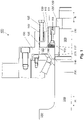
- figure 1 shows the bearing closure device 100 according to the invention in a first embodiment. It is used to pull at least one bearing 200 onto a roll neck 310, to hold the bearing 200 on the roll neck or to release the bearing 200 from the roll neck 310 of a roll.
- the bearing locking device 100 has a threaded ring 110 which can be pushed axially onto a roller shoulder 320 of the roller neck 310 .
- the threaded ring 110 has a first axially extending section 111 which carries an external thread 112 on its outside.
- the threaded ring 110 has a second annular section 113 .
- the second annular section is formed with a smaller outer diameter than the first annular section 111, as a result of which a stop 117 is formed in the transition area between the two sections 111, 113.
- the threaded ring 110 is installed in the bearing locking device in such a way that the first section 111 is located further away from the roll barrel 330 of the roll than the second section 113.
- the bearing locking device 100 also has a stop 120 that can be fastened to the end of the roll shoulder 320 remote from the roll body for limiting the axial movement of the threaded ring 110, which is mounted on the roll shoulder 320 in an axially displaceable manner.
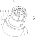
- the stop 120 can either be in the form of a snap ring 120' or in the form of a bayonet catch 120", as in figure 2 shown, be trained.
- the bearing closure device 100 also has a ring nut 130 with an internal thread 132 for screwing onto the external thread 112 of the threaded ring 110.
- the ring nut 130 has a radially outwardly extending flange 138 .
- This flange 138 can be formed with or without axial bores; see also figure 14 .
- the ring nut can also be designed entirely without an outer flange; see figure 15 .
- the bearing locking device 100 has a pressure ring 140 which is mounted on the second annular section 113 of the threaded ring 110 so that it can be displaced in the axial direction R.
- a pressure ring 140 which is mounted on the second annular section 113 of the threaded ring 110 so that it can be displaced in the axial direction R.
- several screws 115 are rotatably mounted in axial threaded bores for pressing against the pressure ring 140 in the axial direction R.
- the bearing locking device 100 has an annular intermediate ring 150 which is designed in such a way that it partially overlaps or engages with at least the radially outer parts of the bearing 200 which do not rotate with the roller. This means that the bearing is pushed onto the roll neck by the intermediate ring or by the pressure ring or is detached or pulled off the roll neck. Intermediate ring 150 and bearing 200 thus form a unit.
- second screws 135 are provided, which are directly or indirectly connected to the intermediate ring 150 and the ring nut 130 to build up an axial force between the intermediate ring 150 and the ring nut 130 for the axial removal of the bearing 200 .
- a total of 3 different variants are distinguished for the design of the intermediate ring 150 and the ring nut 130 for an effective interaction.
- a first variant is in figure 1 shown.
- the ring nut 130 for this first variant has the radially outwardly projecting flange 138 .
- the annular intermediate ring 150 has an axially and radially extending inner flange 152 in its radially inner region. This flange is designed to overlap the outer flange 138 of the ring nut 130 in such a way that the end face of the flange 138 of the ring nut 130 that is remote from the ball and the end face of the flange 152 of the intermediate ring that is close to the ball face each other.
- the second screws 135 can be screwed into axial bores in the flange 152 of the intermediate ring, as in FIG figure 1 shown, to build up an axial force between the intermediate ring 150 and the ring nut 130 when the second screws 135 are screwed against the flange 138 and are supported there.
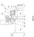
- a second variant for the design of intermediate ring 150 and ring nut 130 is in figure 14 shown.
- a plurality of axially aligned bores are formed in the flange 138 of the ring nut 130 distributed over the circumference of the flange.
- the ring-shaped intermediate ring 150 now does not overlap the flange 138 of the ring nut, but is opposite the end face of the outer flange 138 near the barrel with its radial inner region.
- the intermediate ring 150 has a plurality of axially aligned bores with internal threads distributed over its circumference, the bores in the intermediate ring 150 being aligned with the bores in the flange 138 of the ring nut 130 .
- the second screws 135 can be passed through the bores in the flange 138 of the ring nut and can be screwed into the threaded bores in the intermediate ring 150 in order to build up the tensile stress between the intermediate ring and the ring nut.
- the second screws 135 are tightened, whereby the force builds up between the intermediate ring and the ring nut, because the screws are supported with their screw heads on the flange 138. Due to the form-fitting connection between the intermediate ring 150 and the bearing 200, the bearing is then detached or pulled off the roll neck together with the intermediate ring or with the aid of the intermediate ring; this applies to all three variants.
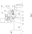
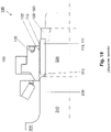
- the third variant is in figure 15 shown.
- an additional ring 170 is provided for axial placement on the end face of the ring nut 130 remote from the ball of the foot.
- the annular intermediate ring 150 faces the periphery of the additional ring 170 with its radial inner region of the end face near the ball.
- the intermediate ring has a plurality of axially aligned bores with internal threads distributed over its circumference, these bores being aligned with the bores in the additional ring 170 .
- the second screws 135 can be passed through the bores in the additional ring 170 and screwed into the bores in the intermediate ring 150 to build up the force between the intermediate ring of the ring nut and the additional ring 170 to release the bearing 200 from the roll neck 310, wherein the screws 135 are supported with their screw heads on the additional ring 170.
- the pressure ring 140 has a pressure measuring cell 160 for detecting a mounting force actually applied by the first screws 115 when the bearing 200 is mounted on the roll neck.
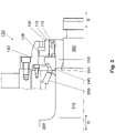
- the method according to the invention for fitting the bearing 200 onto the roll neck 310 of a roll using the bearing locking device 100 has the following steps: First, the bearing is pre-positioned on the roll neck 310 in a positive connection with the bearing locking device 100 .
- the bearing 200 is positioned closer to the roll neck than the bearing closure device 100; the latter will, as in figure 3 shown, rather pre-positioned axially further outward on the roller shoulder 320.
- the pre-positioning of the bearing and the bearing closure device is typically done with a crane or with a hoisting machine.
- the stop 120 for example in the form of the snap ring 120' or the bayonet catch 120" serves as a right-hand path limit for the axial movement of the threaded ring 110.
- the actual positioning of the bearing 200 on the roll neck 310 with a predetermined mounting force is carried out by axially displacing the pressure ring 140 in Figures 3 and 4 example to the left against the bearing 200.
- This axial displacement of the pressure ring 140 and bearing 200 takes place by screwing the first screws 115 into the axial threaded bores in the first annular section 111 of the threaded ring 110 against the pressure ring 140.
- the threaded ring 110 is supported on the axially fixed stop 120, 120'.
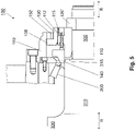
- Said predetermined mounting force is applied by tightening the first screws 115 with a respective predetermined torque using a torque wrench or other suitable tools; please refer figure 5 .
- the ring nut 130 is rotated against the pressure ring 140 and locked in this position in a form-fitting manner; please refer figure 6 .
- the ring nut 130 thus occurs at the Instead of the screws and takes over the maintenance of the necessary mounting force for them even during later operation of the roller and the bearing.
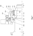
- the first screws 115 can now be turned back and relieved in this way, as in figure 7 shown.
- the camp 200 is raised with it.
- the method according to the invention for detaching or removing the layer from the roll neck has the following steps:
- the initial configuration for the removal process corresponds to the end configuration or the state of the bearing locking device according to the invention at the end of the mounting process, with the only difference that now the second screws 135 are also screwed into the bores in the flange 152 of the intermediate ring 150 .
- These second screws 135 are only relevant for the removal process, but not for the mounting process.
- the starting position for the peeling process is in figure 8 shown.
- the tension between the pressure ring 140 and the ring nut 130 must first be released.
- the first screws 115 are tightened uniformly to a predetermined amount of torque, so that they press against the pressure ring 140 in the axial direction with a predetermined (pull-up) force.
- the first screws 115 are supported on the roll neck via the threaded ring 110 and the stop 120 .
- the pressure ring 140 then transmits the mounting force applied by the first screws 115 to the bearing 200, as a result of which the bearing is mounted a little further onto the roll neck 310.
- the ring nut 130 is thereby free, ie the previously existing axial tension on the pressure ring 140 is reduced in this way; please refer figure 9 .
- the ring nut 130 is then unlocked and rotated back from its stop position in the axial direction away from the roll barrel 330. After turning back the ring nut 130, the screws 115 can also be turned back away from the bearing; please refer figure 11 .
- the bearing 200 Due to the form-fitting connection between the intermediate ring 150 and the bearing 200, the bearing 200 is released from the roll neck due to the force that has built up.
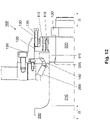
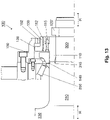
- the second screws 135 can now be removed as shown in figure 13 shown. Subsequently, the stop 120 is then removed and the bearing 200 can then be pulled off the roll neck 310 together with the bearing locking device 100, for example with the aid of a crane.
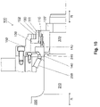
- figure 16 shows a second embodiment of the design of the interaction of roll neck and threaded ring.
- first embodiment is in the now in figure 16 shown second embodiment of the roll neck 310 extended a bit far to the right, so that the pressure ring 140 is now completely mounted on the roll neck 310 axially displaceable.
- second axial section 113 of the threaded ring 110 is completely omitted because it is no longer required as a bearing surface for the pressure ring 140 in this second embodiment; in this second embodiment, without the second section 113, the threaded ring 110 is narrower than in figure 1 with said second Section; Rather, the threaded ring 110 now only extends over the width of the previously first section 111.
- the threaded ring 110 is axially displaceable between the stop 120 or 120' remote from the roll barrel and the stop 315 near the roll barrel. If the ring nut 130 is not set against the pressure ring 140, as in figure 16 shown, the pressure ring between the bearing 200 and the roll body close end face 117 of the threaded ring 110 is mounted axially displaceable.
- FIG 17 shows a third variant of the design of the roll neck in connection with the threaded ring.
- the roll neck 310 is not extended to the right according to FIG figure 16 ; on the contrary, it is designed to be similarly long or short as in the first exemplary embodiment according to FIG figure 1 .
- said second section 113 of the threaded ring 110 is also omitted here; i.e. the width of the threaded ring 110 is reduced to the originally first axial section 111.
- the filling ring 190 is used in the in figure 17 shown embodiment as a carrier or support ring for the pressure ring 140. It is therefore designed with respect to its radial height so that the pressure ring 140 is axially freely displaceable; In particular, its radial height corresponds, for example, to the difference between the outside diameter of roll neck 310 and the outside diameter of roll shoulder 320.
- filler ring 190 remote from the roll barrel now serves as a direct stop near the roll barrel for threaded ring 110, with filler ring 190 itself moving in the event of a stop in turn rests against stop 315; in this respect, the stop 315 remains as an indirect stop for the threaded ring 110 even when the filler ring 190 is used.
- FIG 18 shows a fourth exemplary embodiment for designing the roll neck 310 with the threaded ring 110.
- the roll neck 310 is now designed with a uniform outer diameter throughout; a reduction in the outer diameter in the form of the roller shoulder 320 is now completely eliminated.
- the nut 110 is also limited in width to its first axial portion 111; the axial extension 113 for carrying the pressure ring 140 is omitted entirely, as in the previously described exemplary embodiments 2 and 3. Because the roll neck now has an essentially continuous outer diameter, the pressure ring 140 is again over its entire width in the fourth exemplary embodiment now discussed pushed onto the roll neck. The same applies to the threaded ring 110.
- Both the pressure ring 140 and the threaded ring 110 are now mounted directly on the roll neck 310 in an axially displaceable manner. Because the pressure ring 140 is now slidably mounted on the roll neck, there is no need for the provision of the filling ring 190 as a radial support for the pressure ring 140.
- the stop 120 away from the barrel still serves as a right-hand limit for the movement of the threaded ring 110.
- a key 325 inserted into the threaded ring 110 is now used, which engages in a local axial groove 326 in the surface of the roll neck 310 and, if necessary, abuts against the boundary of the groove 326 near the barrel.
Description
Die Erfindung betrifft eine Verschlussvorrichtung für ein Lager auf einem Walzenzapfen einer Walze zum Walzen von insbesondere metallischem Walzgut. Mit Hilfe des Lagers wird die Walze in einem Walzgerüst drehbar gelagert. Darüber hinaus betrifft die Erfindung ein Verfahren zum Betreiben der Lagerverschlussvorrichtung einerseits zum Aufziehen des Lagers auf den Walzenzapfen und andererseits zum Abziehen des Lagers von dem Walzenzapfen.The invention relates to a locking device for a bearing on a roll neck of a roll for rolling, in particular, metallic rolling stock. With the help of the bearing, the roll is rotatably mounted in a roll stand. In addition, the invention relates to a method for operating the bearing locking device, on the one hand for mounting the bearing on the roll neck and on the other hand for removing the bearing from the roll neck.
Lagerverschlussvorrichtungen sind im Stand der Technik grundsätzlich bekannt. Eine bekannte Lagerverschlussvorrichtung ist beispielsweise in
Das Aufziehen des Lagers 200 auf den Walzenzapfen erfolgt traditionell mit Hilfe eines Krans, mit welchem das Lager zusammen mit der Lagerverschlussvorrichtung 100 zunächst auf dem Walzenzapfen bzw. dem Zapfenabsatz vorpositioniert wird. Nach dieser Vorpositionierung wird der Klappring 120' in einer Nut in dem Walzenabsatz geschlossen oder der Bajonett-Verschluss 120" auf dem Walzenabsatz arretiert, d. h. der Anschlag wird eingerichtet. Nachfolgend wird die Ringmutter 130 mit Hilfe eines Kranseils festgedreht. Dabei verschiebt sich die Ringmutter 130 gemäß
Das Abziehen des Lagers 200 von dem Walzenzapfen erfolgt traditionell wie folgt: Zunächst wird die Ringmutter 130 mittels des Kranseils losgedreht; in
Nachteilig an diesem bekannten Stand der Technik ist die Notwendigkeit, dass die Ringmutter 130 mit Hilfe eines Kranseils entweder festgedreht oder losgedreht werden muss. Diese Vorgehensweise ist gefährlich für eine Bedienperson und ungenau im Hinblick auf eine gewünschte genaue Positionierung des Lagers auf dem Walzenzapfen.A disadvantage of this known prior art is the need for the
Ergänzend wird bezüglich des Standes der Technik auch auf die europäische Patentanmeldung
Die Merkmale des Oberbegriffs des Anspruchs 1 sind offenbart in der
Der Erfindung liegt die Aufgabe zugrunde, eine bekannte Lagerverschlussvorrichtung sowie bekannte Verfahren zum Aufziehen des Lagers auf einen Walzenzapfen und zum Lösen des Lagers von dem Walzenzapfen mit Hilfe der Lagerverschlussvorrichtung sicherer zu machen, insbesondere weil das Kranseil entbehrlich wird, und verwendete Schrauben dauerhaft zu entlasten.The invention is based on the object of making a known bearing locking device and known methods for mounting the bearing on a roll neck and for releasing the bearing from the roll neck with the aid of the bearing locking device safer, in particular because the crane cable is no longer necessary, and to permanently relieve the pressure on the screws used.
Diese Aufgabe wird vorrichtungstechnisch durch die in Anspruch 1 beanspruchte Lagerverschlussvorrichtung gelöst. Demnach ist die erfindungsgemäße Lagerverschlussvorrichtung dadurch gekennzeichnet, dass zwischen dem Lager und dem Gewindering ein Druckring vorgesehen ist, welcher ebenfalls in axialer Richtung verschiebbar gelagert ist, und welcher in radialer Richtung sowohl mit dem Gewindering wie auch mit der Ringmutter zumindest teilweise überlappt; dass in dem Gewindering - über dessen Umfang verteilt - mehrere Schrauben in axialen Gewindebohrungen drehbar gelagert sind zum Drücken in axialer Richtung gegen den Druckring; und dass die Ringmutter in axialer Richtung gegen den Druckring schraubbar und anstellbar ist.In terms of device technology, this object is achieved by the bearing closure device claimed in claim 1 . Accordingly, the bearing locking device according to the invention is characterized in that a pressure ring is provided between the bearing and the threaded ring, which is also mounted to be displaceable in the axial direction and which at least partially overlaps both the threaded ring and the ring nut in the radial direction; that in the threaded ring - distributed over its circumference - several screws are rotatably mounted in axial threaded bores for pressing in the axial direction against the pressure ring; and that the ring nut can be screwed and adjusted in the axial direction against the pressure ring.
Die notwendige Kraft zum Aufziehen des Lagers auf den Walzenzapfen erfolgt erfindungsgemäß zunächst mit Hilfe der Schrauben, welche mit einem Momentenschlüssel oder sonstigen geeigneten Werkzeugen angezogen werden. Dadurch wird die gefährliche Verwendung eines Kranseils zum Aufbringen der notwendigen Aufziehkraft für das Lager entbehrlich. Damit die Schrauben jedoch während des Betriebs des Lagers und der Walze nicht permanent unter Druck stehen müssen, wird, wie weiter unten bei der Beschreibung der erfindungsgemäßen Verfahren deutlich werden wird, die Ringmutter gegen den Druckring geschraubt, bis sie gegen diesen anschlägt. Der Druckring und damit auch das Lager werden durch die Ringmutter in ihrer axialen Position fixiert. Die Schrauben werden dann vor Inbetriebnahme zurückgedreht und dadurch von der axialen Druckkraft entlastet.According to the invention, the force required to pull the bearing onto the roll neck is initially applied with the aid of the screws, which are tightened with a torque wrench or other suitable tools. This eliminates the dangerous use of a crane rope to apply the necessary pull-up force for the storage unnecessary. However, so that the screws are not permanently under pressure during operation of the bearing and the roller must stand, as will become clear below in the description of the method according to the invention, the ring nut is screwed against the pressure ring until it strikes against it. The pressure ring and thus also the bearing are fixed in their axial position by the ring nut. The screws are then turned back before they are put into operation, thereby relieving them of the axial compressive force.
Ähnliches gilt auch für den Vorgang des Lösens bzw. Abziehen des Lagers von dem Walzenzapfen. Auch hier dienen die Schrauben in dem Gewindering nur kurzzeitig zum Entkoppeln von Druckring und Ringmutter; nur dafür sind die Schrauben in dem Gewindering kurzzeitig axial stark belastet; danach werden sie wieder zurückgeschraubt und dadurch axial entlastet.The same also applies to the process of releasing or removing the bearing from the roll neck. Here, too, the screws in the threaded ring only serve to decouple the pressure ring and ring nut for a short time; this is the only reason why the screws in the threaded ring are subjected to a high axial load for a short period of time; then they are screwed back again and thereby relieved axially.
Gemäß einem ersten Ausführungsbeispiel umfasst die Lagerverschlussvorrichtung weiterhin einen ringförmigen Abschlussdeckel zum Übergreifen von zumindest radial äußeren - nicht mit der Walze mitdrehenden - Teilen des Lagers. Anders ausgedrückt ist der Abschlussdeckel so ausgebildet, dass er mit dem Lager derart in Eingriff steht, dass bei Aufbringen einer axialen Kraft an dem Abschlussdeckel das Lager axial von dem Walzenzapfen mit abgezogen wird. Zum Aufbringen der Kraft dienen erfindungsgemäß Schrauben, welche direkt oder indirekt mit dem Abschlussdeckel und der Ringmutter in Verbindung stehen zum Aufbauen einer axialen Spannung zwischen dem Abschlussdeckel und der Ringmutter für das axiale Abziehen des Lagers.According to a first exemplary embodiment, the bearing locking device also includes an annular end cap for overlapping at least radially outer parts of the bearing—not rotating with the roller. In other words, the end cap is designed in such a way that it engages with the bearing in such a way that when an axial force is applied to the end cap, the bearing is pulled off the roll neck axially as well. According to the invention, the force is applied using screws which are directly or indirectly connected to the end cap and the ring nut in order to build up an axial tension between the end cap and the ring nut for the axial removal of the bearing.
Verschiedene Ausgestaltungen des Abschlussdeckels und der Ringmutter sind Gegenstand der abhängigen Ansprüche.Various configurations of the end cap and the ring nut are the subject matter of the dependent claims.
Weiterhin sind verschiedene Ausführungsbeispiele für den walzenballenfernen Anschlag Gegenstand der abhängigen Ansprüche. So kann dieser walzenballenferne Anschlag beispielsweise als Klappring oder als Bajonett-Verschluss ausgebildet sein.Furthermore, various exemplary embodiments for the stop remote from the roll barrel are the subject matter of the dependent claims. For example, this stop remote from the roll barrel can be designed as a snap ring or as a bayonet lock.
Der Druckring kann zumindest teilweise beispielsweise auf einer Verlängerung (2. Abschnitt) des Gewinderings in Richtung des Lagers, auf dem Walzenzapfen oder auf einem Füllring zwischen Lager und Gewindering axial verschiebbar gelagert sein.The pressure ring can be mounted at least partially, for example on an extension (section 2) of the threaded ring in the direction of the bearing, on the roll neck or on a filler ring between the bearing and the threaded ring in an axially displaceable manner.
Für das Abziehen des Lagers von dem Walzenzapfen ist es erforderlich, dass der Gewindering in seiner axialen Bewegung auf den Walzenballen hin begrenzt wird und sich an einem walzenballennahen Anschlag abstützen kann. Dieser kann beispielsweise dadurch ausgebildet sein, dass ein zweiter ringförmiger Abschnitt des Walzenzapfens, d. h. der Walzenabsatz, mit einem kleineren Durchmesser ausgebildet ist als der erste ringförmige Abschnitt des Walzenzapfens. Alternativ kann der walzenballennahe Anschlag für den Gewindering auch durch eine Art Passfeder in dem Walzenzapfen auf Höhe des Gewinderings ausgebildet sein.In order to remove the bearing from the roll neck, it is necessary for the threaded ring to be limited in its axial movement towards the roll barrel and to be able to be supported on a stop near the roll barrel. This can be formed, for example, in that a second annular section of the roll neck, i. H. the roll shoulder, is formed with a smaller diameter than the first annular portion of the roll neck. Alternatively, the stop for the threaded ring close to the roll barrel can also be formed by a type of feather key in the roll neck at the height of the threaded ring.
Das Aufziehen des Lagers auf den Walzenzapfen erfolgt vorzugsweise mit einer vorbestimmten axialen Kraft. Um diese Aufziehkraft kontrollieren zu können, ist es erfindungsgemäß optional vorgesehen, dass der Druckring eine Druckmesszelle aufweisen bzw. aufweist zum Erfassen der tatsächlich aufgebrachten Aufziehkraft.The bearing is preferably mounted on the roll neck with a predetermined axial force. In order to be able to control this pull-on force, it is optionally provided according to the invention that the pressure ring has or has a pressure measuring cell for detecting the pull-on force actually applied.
Die oben genannte Aufgabe der Erfindung wird weiterhin durch ein Verfahren zum Aufziehen des Lagers auf den Walzenzapfen sowie durch ein Verfahren zum Lösen bzw. Abziehen des Lagers von dem Walzenzapfen, jeweils mit Hilfe der erfindungsgemäßen Lagerverschlussvorrichtung gelöst. Die Vorteile dieser Verfahren entsprechen den oben mit Bezug auf die beanspruchte Lagerverschlussvorrichtung genannten Vorteilen.The above-mentioned object of the invention is also achieved by a method for fitting the bearing onto the roll neck and by a method for loosening or removing the bearing from the roll neck, each with the aid of the bearing locking device according to the invention. The advantages of these methods correspond to the advantages mentioned above in relation to the claimed bearing closure device.
Der Beschreibung sind insgesamt 19 Figuren beigefügt, wobei
- Figur 1
- die erfindungsgemäße Lagerverschlussvorrichtung mit jeweils einem ersten Ausführungsbeispiel für den erfindungsgemäßen walzenballenfernen Anschlag, für eine Abschlussdeckel-Ringmutter-Ausgestaltung und für eine Walzenzapfen-Gewindering-Ausgestaltung;
- Figur 2
- ein zweites Ausführungsbeispiel für den walzenballenfernen Anschlag;
- Figuren 3-7
- das Aufziehen eines Lagers auf einen Walzenzapfen mit Hilfe der erfindungsgemäßen Lagerverschlussvorrichtung;
- Figuren 8-13
- das Abziehen bzw. Lösen des Lagers von dem Walzenzapfen;
- Figur 14
- ein zweites Ausführungsbeispiel für eine erfindungsgemäße Abschlussdeckel-Ringmutter-Ausgestaltung;
- Figur 15
- ein drittes Ausführungsbeispiel für eine erfindungsgemäße Abschlussdeckel-Ringmutter-Ausgestaltung;
- Figur 16
- ein zweites Ausführungsbeispiel für die Walzenzapfen-Gewindering-Ausgestaltung;
- Figur 17
- ein drittes Ausführungsbeispiel für die Walzenzapfen-Gewindering-Ausgestaltung;
- Figur 18
- ein viertes Ausführungsbeispiel für die Walzenzapfen-Gewindering-Ausgestaltung; und
- Figur 19
- eine bekannte Lagerverschlussvorrichtung aus dem Stand der Technik
- figure 1
- the bearing closure device according to the invention, each with a first embodiment of the invention stopper away from the roll body, for an end cap ring nut design and for a roll neck ring nut design;
- figure 2
- a second exemplary embodiment for the stop remote from the roll barrel;
- Figures 3-7
- mounting a bearing on a roll neck using the bearing locking device according to the invention;
- Figures 8-13
- withdrawing the bearing from the roll neck;
- figure 14
- a second exemplary embodiment of an end cap ring nut design according to the invention;
- figure 15
- a third exemplary embodiment of an end cap ring nut design according to the invention;
- figure 16
- a second embodiment of the roll neck nut design;
- figure 17
- a third embodiment of the roll neck nut design;
- figure 18
- a fourth embodiment of the roll neck nut design; and
- figure 19
- a well-known bearing closure device from the prior art
Die Erfindung wird nachfolgend unter Bezugnahme auf die genannten
Die Lagerverschlussvorrichtung 100 weist einen Gewindering 110 auf, welcher auf einen Walzenabsatz 320 des Walzenzapfens 310 axial aufschiebbar ist. Der Gewindering 110 weist einen ersten sich axial erstreckenden Abschnitt 111 auf, welcher an seiner Außenseite ein Außengewinde 112 trägt. Neben dem ersten ringförmigen Abschnitt 111 weist der Gewindering 110 einen zweiten ringförmigen Abschnitt 113 auf. Typischerweise ist der zweite ringförmige Abschnitt mit einem kleineren Außendurchmesser ausgebildet als der erste ringförmige Abschnitt 111, wodurch im Übergangsbereich zwischen den beiden Abschnitten 111, 113 ein Anschlag 117 ausgebildet wird. Der Gewindering 110 ist derart in der Lagerverschlussvorrichtung eingebaut, dass der erste Abschnitt 111 weiter entfernt von dem Walzenballen 330 der Walze angeordnet ist als der zweite Abschnitt 113.The
Die erfindungsgemäße Lagerverschlussvorrichtung 100 weist weiterhin einen an dem walzenballenfernen Ende des Walzenabsatzes 320 befestigbaren Anschlag 120 auf zum Begrenzen der axialen Bewegung des Gewinderinges 110, welcher auf dem Walzenabsatz 320 axial verschiebbar gelagert ist. Der Anschlag 120 kann entweder in Form eines Klappringes 120' oder in Form eines Bajonett-Verschlusses 120", wie in
Die erfindungsgemäße Lagerverschlussvorrichtung 100 weist weiterhin eine Ringmutter 130 auf mit einem Innengewinde 132 zum Aufschrauben auf das Außengewinde 112 des Gewinderings 110. Bei dem in
Wie in
Weiterhin weist die Lagerverschlussvorrichtung 100 einen ringförmigen Zwischenring 150 auf, welcher so ausgebildet ist, dass er zumindest die radial äußeren - nicht mit der Walze mitdrehenden - Teile des Lagers 200 teilweise übergreift bzw. mit diesen in Eingriff steht. Dies bedeutet, dass das Lager von dem Zwischenring bzw. von dem Druckring auf den Walzenzapfen aufgeschoben oder von dem Walzenzapfen gelöst bzw. abgezogen wird. Zwischenring 150 und Lager 200 bilden somit eine Einheit.Furthermore, the
Neben den ersten Schrauben 115 in dem Gewindering 110 sind zweite Schrauben 135 vorgesehen, welche direkt oder indirekt mit dem Zwischenring 150 und der Ringmutter 130 in Verbindung stehen zum Aufbau einer axialen Kraft zwischen dem Zwischenring 150 und der Ringmutter 130 für das axiale Abziehen des Lagers 200.In addition to the
Gemäß der vorliegenden Erfindung werden insgesamt 3 verschiedene Varianten für die Ausgestaltung des Zwischenrings 150 und der Ringmutter 130 für ein wirkungsvolles Zusammenwirken unterschieden.According to the present invention, a total of 3 different variants are distinguished for the design of the
Eine erste Variante ist in
Eine zweite Variante für die Ausgestaltung von Zwischenring 150 und Ringmutter 130 ist in
Die dritte Variante ist in
Wieder bezugnehmend auf
Das erfindungsgemäße Verfahren zum Aufziehen des Lagers 200 auf den Walzenzapfen 310 einer Walze mit Hilfe der erfindungsgemäßen Lagerverschlussvorrichtung 100 weist folgende Schritte auf:
Zunächst wird das Lager in formschlüssiger Verbindung mit der Lagerverschlussvorrichtung 100 auf dem Walzenzapfen 310 vorpositioniert. Dabei wird das Lager 200 ballennäher auf dem Walzenzapfen positioniert als die Lagerverschlussvorrichtung 100; letztere wird, wie in
First, the bearing is pre-positioned on the
Die Vorpositionierung des Lagers und der Lagerverschlussvorrichtung erfolgen typischerweise mit einem Kran oder mit einer Aufziehmaschine. Nach der Vorpositionierung wird der Anschlag 120 gemäß
Nachdem die vorbestimmte Aufziehkraft in der beschriebenen Weise aufgebracht wurde, wird die Ringmutter 130 gegen den Druckring 140 gedreht und in dieser Position formschlüssig arretiert; siehe
Das erfindungsgemäße Verfahren zum Lösen bzw. Abziehen des Lages von dem Walzenzapfen weist folgende Schritte auf:
Die Ausgangskonstellation für den Abziehvorgang entspricht der Endkonfiguration bzw. dem Zustand der erfindungsgemäßen Lagerverschlussvorrichtung am Ende des Aufziehvorganges mit dem einzigen Unterschied, dass nunmehr auch die zweiten Schrauben 135 in die Bohrungen in dem Flansch 152 des Zwischenrings 150 eingeschraubt sind. Diese zweiten Schrauben 135 sind lediglich für den Abziehvorgang, nicht jedoch für den Aufziehvorgang relevant.The method according to the invention for detaching or removing the layer from the roll neck has the following steps:
The initial configuration for the removal process corresponds to the end configuration or the state of the bearing locking device according to the invention at the end of the mounting process, with the only difference that now the
Die Ausgangsposition für den Abziehvorgang ist in
In
Die
Nach wie vor ist der Gewindering 110 jedoch axial verschiebbar zwischen dem walzenballenfernen Anschlag 120 bzw. 120' und dem walzenballennahen Anschlag 315. Sofern die Ringmutter 130 nicht gegen den Druckring 140 angestellt ist, wie in
Bei allen vier beschriebenen Ausführungsbeispielen gemäß den
- 100100
- Lagerverschlussvorrichtungstorage locking device
- 110110
- Gewinderingthreaded ring
- 111111
- erster ringförmiger Abschnitt des Gewinderingsfirst annular section of the ring nut
- 112112
- Außengewindeexternal thread
- 113113
- zweiter ringförmiger Abschnitt des Gewinderingssecond annular section of the ring nut
- 115115
- erste Schraubenfirst screws
- 117117
- Anschlag für den DruckringStop for the pressure ring
- 120120
- Anschlagattack
- 120'120'
- Klappringsnap ring
- 120"120"
- Bajonett-Verschlussbayonet lock
- 130130
- Ringmutterring nut
- 132132
- Innengewindeinner thread
- 135135
- zweite Schraubensecond screws
- 138138
- äußerer Flanschouter flange
- 140140
- Druckringpressure ring
- 150150
- Zwischenringintermediate ring
- 152152
- innerer Flansch des Zwischenringesinner flange of the intermediate ring
- 160160
- Druckmesszellepressure cell
- 170170
- Zusatzringauxiliary ring
- 190190
- Füllringfilling ring
- 200200
- Lagerwarehouse
- 310310
- Walzenzapfen, insbesondere erster ringförmiger Abschnitt des WalzenzapfensRoll neck, in particular first annular section of the roll neck
- 315315
- walzenballennaher Anschlag in Walzenzapfenstop close to the roll body in the roll neck
- 320320
- Walzenabsatz (= zweiter ringförmiger Abschnitt des Walzenzapfens)Roll shoulder (= second ring-shaped section of the roll neck)
- 325325
- PassfederAdjusting spring
- 326326
- axiale Nutaxial groove
- 330330
- Walzenballenroll barrel
- RR
- axiale Richtungaxial direction
Claims (16)
- Bearing closure device (100) for securing at least one bearing (200) on a roll journal (310) of a roll, wherein the bearing (200) is constructed for mounting the roll in a roll stand and wherein the bearing closure device (100) comprises:a threaded ring (110), which is pushable onto the roll journal (310) and mountable thereon to be axially displaceable, with an external thread (112);a stop (120), which is remote from the roll barrel, and a stop (315) which is adjacent to the roll barrel, for limiting the axial movement of the threaded ring (110); andan annular nut (130) with an internal thread (132) for screwing onto the external thread (112) of the threaded ring (110);characterised in thata pressure ring (140), which is similarly mounted to be displaceable in axial direction (R) and which in radial direction at least partly overlaps not only the threaded ring (110), but also the annular nut (130), is provided between the bearing and the threaded ring (110);several screws (115) distributed over the circumference of the threaded ring (110) are rotatably mounted in the threaded ring in axial threaded bores for pressing in axial direction (R) against the threaded ring (140); andthe annular nut (130) can be screwed and adjusted in axial direction against the pressure ring (140).
- Bearing closure device (100) according to claim 1,
characterised byan annular intermediate ring (150); andscrews (135) connected directly or indirectly with the intermediate ring (150) and the annular nut (130) to build up an axial force between the intermediate ring (150) and the annular nut (130) for axially drawing off the bearing (200). - Bearing closure device (100) according to claim 2,
characterised in thatthe annular nut (130) has a radially outwardly projecting flange (138);the annular intermediate ring (150) has in its radially inner region an axially and radially extending inner flange (152) which is constructed to engage over the outer flange (138) of the annular nut (130) in such a way that the end, which is remote from the barrel, of the flange (138) of the annular nut (130) and the end, which is adjacent to the barrel, of the flange (152) of the intermediate ring (150) are opposite one another; andthe screws (135) can be screwed into axial threaded bores in the flange (152) of the intermediate ring (150) to build up the axial force between the intermediate ring (150) and the annular nut (130) by support of the screws (135) on the outer flange (138) of the annular nut (130). - Bearing closure device (100) according to claim 2,
characterised in thatthe annular nut (130) has an radially outwardly projecting flange (138) which has a plurality of axially oriented bores distributed over its circumference;the annular intermediate ring (150) at its radial inner region is opposite the end, which is adjacent to the barrel, of the outer flange (138) of the annular nut (130) and at its radially inner region has a plurality of axially oriented bores, which are distributed over its circumference, with internal threads, wherein the bores in the intermediate ring (150) are aligned with the bores in the flange (138) of the annular nut (130); andthe screws (135) can be passed through the bores in the flange (138) of the annular nut (130) and screwed into the bores in the intermediate ring to build up the force between the intermediate ring (150) and the annular nut (130) for releasing the bearing (200) from the roll journal (310), wherein the screws (135) are supported by the screw heads thereof on the flange (138). - Bearing closure device (100) according to claim 2,
characterised in thatan auxiliary ring (170) is provided for axial positioning on the end, which is remote from the barrel, of the annular nut (130), wherein the auxiliary ring (170) has at its periphery a plurality of axially oriented bores which distributed over the circumference of the auxiliary ring and which are formed radially outwardly of the annular nut (130);the annular intermediate ring (150) by its radial inner region is opposite the end, which is adjacent to the barrel, of the periphery of the auxiliary ring (170) and has at its radially inner region a plurality of axially oriented bores, which are distributed over the circumference of the auxiliary ring, with internal threads, where the bores in the closure cover (140) are aligned with the bores in the auxiliary ring (170); andthe screws (135) can be passed through the bores in the auxiliary ring and screwed into the bores in the closure cover for build up of the force between the intermediate ring (150), the annular nut (130) and the auxiliary ring (170) for releasing the bearing (200) from the roll journal (310), wherein the screws (135) are supported by the screw heads thereof on the auxiliary ring (170). - Bearing closure device (100) according to any one of the preceding claims,
characterised in that
the stop (120), which is remote from the roll barrel, for the threaded ring (110) is formed by a hinged ring (120') which is insertable into an encircling groove in the roll journal (310) to be axially fixed. - Bearing closure device (100) according to any one of claims 1 to 5,
characterised in that
the stop (120), which is remote from the roll barrel, for the threaded ring (110) is formed by a bayonet coupling (120") which is axially fixable on the roll journal (320) in axial direction (R). - Bearing closure device (100) according to any one of claims 1 to 7,
characterised in thatthe longitudinal section of the threaded ring (110) together with the external thread (112) represents a first annular section (111), which extends in axial direction, of the threaded ring; the threaded ring (110) has at its end facing the bearing (200) an extension which represents a second annular section (113), which extends in axial direction, of the threaded ring (110); andthe pressure ring (140) is mounted on the second annular section (113) of the threaded ring (110) to be displaceable in axial direction. - Bearing closure device (100) according to claim 8,
characterised in that
the second annular section (113) is formed with a smaller diameter than the first annular section (111), whereby a shoulder is formed in the threaded ring (110) between the first and the second section (113) as stop (117), which is remote from the roll barrel, for the pressure ring (140). - Bearing closure device (100) according to any one of the preceding claims,
characterised in that
the pressure ring (140) has a pressure measuring cell (160) for detecting the actually applied drawing-on force. - System comprising a roll, which has a roll journal, and a bearing closure device (100) according to any one of the preceding claims,
characterised in thatthe roll journal (310) is constructed at its end, which is remote from the roll barrel, in the form of a roll shoulder (320) with reduced diameter, wherein the threaded ring (110) is mounted on the roll shoulder (320) to be axially displaceable and the stop (120), which is remote from the roll barrel, for the threaded ring (110) is axially fixed on the roll shoulder (320); andthe stop (315), which is adjacent to the roll barrel, for the threaded ring is formed by a shoulder in the roll journal in the region of transition to the roll shoulder. - System according to claim 11,
characterised in that
a filling ring (190) is mounted on the roll journal between the stop (315) in the roll journal and the threaded ring (110) to be displaceable, wherein the radial height of the intermediate ring corresponds with, for example, the difference between the diameter of the roll journal and the diameter of the roll shoulder. - System according to one of claims 11 and 12,
characterised in that
the pressure ring (140) is mounted at least partly on the roll journal and/or on the filling ring (190) and/or on the threaded ring (110) to be displaceable in axial direction. - Method for drawing a bearing (200) onto the roll journal (310) of a roll with the help of the bearing closure device (100) according to any one of the preceding claims 1 to 10, comprising the following steps:pre-positioning the bearing (200) adjacent to the roll barrel and the bearing closure device (100) remote from the roll barrel on the roll journal (310);axially fixing the stop (120', 120"), which is remote from the roll barrel, on the roll journal (310); further drawing of the bearing (200) onto the roll journal (310) by axial displacement of the pressure ring (140) and thus of the bearing (200) in the direction of the roll barrel (330) by screwing the screws (115) into the axial threaded bores in the threaded ring (110) against the pressure ring (140), wherein the threaded ring is supported on the axially fixed stop (120', 120") remote from the roll barrel;turning the annular nut (130) on the external thread (112) of the threaded ring (140) until it abuts the pressure ring (140);locking the annular nut (130) in its abutment position against the pressure ring (140); andturning the screws (115) back from the pressure ring (140).
- Method according to claim 14,
characterised in thatthe screws (115) are tightened in the threaded bores for drawing-on the bearing (200) in each instance up to a predetermined torque or up to a predetermined drawing-on force; andthe annular nut (130) is mounted for contact with the pressure ring (140) only after the screws (115) have been tightened to the predetermined torque or the predetermined drawing-on force. - Method for drawing a bearing (200) off the roll journal (310) of the roll with the help of the bearing closure device (100) according to any one of claims 1 to 10 after the bearing (200) has been previously tightened on the roll journal in accordance with, for example, the method according to one of claims 14 and 15, comprising the following steps:displacing the pressure ring (140) and thus the bearing (200) some distance in the direction of the roll barrel (330) for build up of the axial bias between the annular nut (130) and the pressure ring (140) by screwing the screws (115) into the axial threaded bores in the threaded ring (110) against the pressure ring (140), wherein the threaded ring is supported on the axially fixed stop (120', 120") remote from the roll barrel;unlocking and turning back the annular nut (130) in axial direction (R) away from the roll barrel; turning back the screws (115);tightening the screws (135) for build up of a force between the intermediate ring (150) and the annular nut (130) for releasing or drawing-off the bearing (200) from the roll journal (310), wherein the threaded ring, which is engaged by way of its external thread (112) with the annular nut (130), is displaced some distance in axial direction (R) towards the roll barrel (330) and is supported in the roll journal by way of a stop (315, 325 with 326) adjacent to the roll barrel;removing the stop (120', 120") remote from the roll barrel; andaxial drawing off the released bearing (200) together with the bearing closure device (100), for example with the help of a crane, from the roll journal.
Applications Claiming Priority (3)
| Application Number | Priority Date | Filing Date | Title |
|---|---|---|---|
| DE102017209304 | 2017-06-01 | ||
| DE102017217562.1A DE102017217562A1 (en) | 2017-06-01 | 2017-10-04 | Bearing locking device and method for its operation |
| PCT/EP2018/063895 WO2018219850A1 (en) | 2017-06-01 | 2018-05-28 | Bearing closure device and method for operating same |
Publications (2)
| Publication Number | Publication Date |
|---|---|
| EP3630381A1 EP3630381A1 (en) | 2020-04-08 |
| EP3630381B1 true EP3630381B1 (en) | 2022-08-17 |
Family
ID=64279316
Family Applications (1)
| Application Number | Title | Priority Date | Filing Date |
|---|---|---|---|
| EP18735503.7A Active EP3630381B1 (en) | 2017-06-01 | 2018-05-28 | Bearing closure device and method for operating same |
Country Status (8)
| Country | Link |
|---|---|
| US (1) | US11261907B2 (en) |
| EP (1) | EP3630381B1 (en) |
| JP (1) | JP6920476B2 (en) |
| KR (1) | KR102327797B1 (en) |
| CN (1) | CN110678273B (en) |
| DE (1) | DE102017217562A1 (en) |
| RU (1) | RU2732458C1 (en) |
| WO (1) | WO2018219850A1 (en) |
Families Citing this family (5)
| Publication number | Priority date | Publication date | Assignee | Title |
|---|---|---|---|---|
| DE202021001817U1 (en) | 2021-05-21 | 2021-07-05 | Sms Group Gmbh | Journal bushing as part of an oil film bearing |
| DE102021205276A1 (en) | 2021-05-21 | 2021-07-22 | Sms Group Gmbh | Journal bushing as part of an oil film bearing |
| CN113550982B (en) * | 2021-08-18 | 2022-07-29 | 闻军 | Make things convenient for bearing block fastening's bearing frame |
| CN114571407A (en) * | 2022-03-21 | 2022-06-03 | 吉林大学 | Bearing disassembling tool suitable for different main shaft sizes |
| CN114714064B (en) * | 2022-05-06 | 2023-07-18 | 南京晨光集团有限责任公司 | Knuckle bearing rolling tool |
Family Cites Families (20)
| Publication number | Priority date | Publication date | Assignee | Title |
|---|---|---|---|---|
| FR1254487A (en) * | 1960-01-12 | 1961-02-24 | Timken Roller Bearing Co | Mounting of bearings intended for use on tapered trunnions of rolling mill rolls and the like |
| US3080199A (en) | 1961-09-01 | 1963-03-05 | Morgan Construction Co | Integral bearing mounting and dismounting means |
| US3966282A (en) | 1973-08-31 | 1976-06-29 | Republic Steel Corporation | Bearing chocking assembly for mill rolls |
| SU820944A1 (en) | 1979-06-13 | 1981-04-15 | Ижевский механический институт | Rolling roll bearing assembly |
| US4286830A (en) * | 1979-09-24 | 1981-09-01 | Morgan Construction Company | Combination roll neck and bearing assembly |
| JPS6069825U (en) | 1983-10-20 | 1985-05-17 | 日本精工株式会社 | Roller bearing device for axle of railway vehicle |
| US4938615A (en) | 1989-10-26 | 1990-07-03 | The Timken Company | Roll neck bearing |
| RU2048220C1 (en) | 1993-10-08 | 1995-11-20 | Акционерное общество "Северсталь" | Device for radial and axial adjustment of stand roll |
| JPH1015610A (en) | 1996-07-02 | 1998-01-20 | Kobe Steel Ltd | Method and device for delivering steel bar onto cooling bed |
| DE19819063A1 (en) * | 1998-04-29 | 1999-11-04 | Schloemann Siemag Ag | Straightening machine for rolled beams |
| US6132101A (en) * | 1999-07-28 | 2000-10-17 | Voest Alpine Industries, Inc. | Roll bearing assembly having integral components |
| US6415489B1 (en) | 1999-07-29 | 2002-07-09 | Morgan Construction Company | Hydraulically actuated tool for mounting and dismounting rolling mill roll neck bearings |
| DE19945070A1 (en) * | 1999-09-20 | 2001-03-22 | Sms Demag Ag | Device for mounting and removing a support roller bearing unit |
| US7500374B2 (en) * | 2007-04-03 | 2009-03-10 | Morgan Construction Company | Apparatus for urging an oil film bearing onto and off of a roll neck in a rolling mill |
| US20100000375A1 (en) | 2008-07-07 | 2010-01-07 | Steinbock Robert C | Tamper resistant jackbolts for a tensioner |
| DE102010064102B4 (en) | 2010-12-23 | 2014-09-25 | Sms Siemag Ag | Bearing arrangement and rolling unit for a rolling mill roll |
| CN104438990B (en) * | 2014-10-15 | 2016-11-23 | 张家港中环海陆特锻股份有限公司 | A kind of large-scale vertical is combined machine for rolling ring and control method |
| CN204448832U (en) | 2014-12-29 | 2015-07-08 | 鞍钢股份有限公司 | Roll bearing box retaining ring in high-speed rod-rolling mill |
| CN204610423U (en) | 2015-01-27 | 2015-09-02 | 博斯特(上海)有限公司 | A kind of rotary-piston for printing plate cylinder locking |
| CN204710856U (en) | 2015-06-19 | 2015-10-21 | 邯钢集团邯宝钢铁有限公司 | A kind of snap joint locking device of improvement |
-
2017
- 2017-10-04 DE DE102017217562.1A patent/DE102017217562A1/en not_active Withdrawn
-
2018
- 2018-05-28 JP JP2019566072A patent/JP6920476B2/en active Active
- 2018-05-28 RU RU2019138553A patent/RU2732458C1/en active
- 2018-05-28 WO PCT/EP2018/063895 patent/WO2018219850A1/en active Application Filing
- 2018-05-28 KR KR1020197038253A patent/KR102327797B1/en active IP Right Grant
- 2018-05-28 CN CN201880036307.3A patent/CN110678273B/en active Active
- 2018-05-28 EP EP18735503.7A patent/EP3630381B1/en active Active
- 2018-05-28 US US16/618,341 patent/US11261907B2/en active Active
Also Published As
| Publication number | Publication date |
|---|---|
| JP6920476B2 (en) | 2021-08-18 |
| JP2020521922A (en) | 2020-07-27 |
| EP3630381A1 (en) | 2020-04-08 |
| US20210140470A1 (en) | 2021-05-13 |
| KR20200011484A (en) | 2020-02-03 |
| WO2018219850A1 (en) | 2018-12-06 |
| BR112019025260A2 (en) | 2020-06-23 |
| CN110678273A (en) | 2020-01-10 |
| KR102327797B1 (en) | 2021-11-17 |
| DE102017217562A1 (en) | 2018-12-06 |
| CN110678273B (en) | 2021-03-26 |
| US11261907B2 (en) | 2022-03-01 |
| RU2732458C1 (en) | 2020-09-16 |
Similar Documents
| Publication | Publication Date | Title |
|---|---|---|
| EP3630381B1 (en) | Bearing closure device and method for operating same | |
| DE60202882T2 (en) | HYDRAULIC FASTENING AND SOLDERING DEVICE FOR ROLLING TAP BEARINGS AND METHOD FOR THEIR USE | |
| EP1426639B1 (en) | Method for mounting a two row tapered roller bearing with segmented bearing rings in a wind motor | |
| EP2673526B1 (en) | Wheel bearing for a vehicle wheel, and wheel hub for fastening a vehicle wheel | |
| WO2012100933A1 (en) | Method and device for changing a gasket in an aircraft engine | |
| EP0748421A1 (en) | Clamping arrangement having a tapered clamping bolt | |
| DD284953A5 (en) | LATCH FOR THE TRANSMISSION OF TORQUE AND / OR AXIAL CROSSINGS | |
| DE2929335A1 (en) | DEVICE FOR THE AXIAL ADJUSTMENT OF ROLLING MILLS | |
| EP3658785B1 (en) | Expansion bolt, and connection assembly comprising such an expansion bolt | |
| EP3439805B1 (en) | Device and method for pulling a bearing onto a roll journal and for pulling the bearing off the roll journal | |
| EP0299324B1 (en) | Remotely controllable tube connection and multi-purpose tool therefor | |
| DE2035698C3 (en) | Roll neck bearing | |
| DE2118627A1 (en) | Device for installing and removing a roll bearing for a roll stand | |
| DE102010064102B4 (en) | Bearing arrangement and rolling unit for a rolling mill roll | |
| EP0348740B1 (en) | Remotely controllable screw connection | |
| EP3180231B1 (en) | Track rod or steering rod for a vehicle | |
| DE4227476C1 (en) | Shaft coupling with two connecting flanges and interposed multi-plate assembly - has specially dimensioned screw bolt shaft cylinder sections associated with centring bushes for play-free support. | |
| WO2020025828A1 (en) | Motor spindle for a machine, particularly for a machine tool, with braced bearing arrangement, and method for mounting a motor spindle of this kind | |
| DE102007017700A1 (en) | Securing device for groove nut during shaft-hub-connection, has groove nut, which is aligned in shaft through pin, placed axially in bore | |
| DE19510117A1 (en) | Anchoring nut for concrete-shuttering tie-bar | |
| DE112006000547B4 (en) | Hydraulic cylinder piston | |
| DE19605034C1 (en) | Device for releasable axial fixing of bearings | |
| EP3206930B1 (en) | Cable roller, in particular for a roller battery of a cableway installation | |
| WO2016165816A1 (en) | Foundation anchoring for a working machine | |
| DE10033684B4 (en) | turning gear |
Legal Events
| Date | Code | Title | Description |
|---|---|---|---|
| STAA | Information on the status of an ep patent application or granted ep patent |
Free format text: STATUS: UNKNOWN |
|
| STAA | Information on the status of an ep patent application or granted ep patent |
Free format text: STATUS: THE INTERNATIONAL PUBLICATION HAS BEEN MADE |
|
| PUAI | Public reference made under article 153(3) epc to a published international application that has entered the european phase |
Free format text: ORIGINAL CODE: 0009012 |
|
| STAA | Information on the status of an ep patent application or granted ep patent |
Free format text: STATUS: REQUEST FOR EXAMINATION WAS MADE |
|
| 17P | Request for examination filed |
Effective date: 20200102 |
|
| AK | Designated contracting states |
Kind code of ref document: A1 Designated state(s): AL AT BE BG CH CY CZ DE DK EE ES FI FR GB GR HR HU IE IS IT LI LT LU LV MC MK MT NL NO PL PT RO RS SE SI SK SM TR |
|
| AX | Request for extension of the european patent |
Extension state: BA ME |
|
| DAV | Request for validation of the european patent (deleted) | ||
| DAX | Request for extension of the european patent (deleted) | ||
| GRAP | Despatch of communication of intention to grant a patent |
Free format text: ORIGINAL CODE: EPIDOSNIGR1 |
|
| STAA | Information on the status of an ep patent application or granted ep patent |
Free format text: STATUS: GRANT OF PATENT IS INTENDED |
|
| INTG | Intention to grant announced |
Effective date: 20220303 |
|
| RIN1 | Information on inventor provided before grant (corrected) |
Inventor name: WILL, ROLAND Inventor name: KNIE, DANIEL Inventor name: TUCAK, ANDREJ |
|
| GRAS | Grant fee paid |
Free format text: ORIGINAL CODE: EPIDOSNIGR3 |
|
| GRAA | (expected) grant |
Free format text: ORIGINAL CODE: 0009210 |
|
| STAA | Information on the status of an ep patent application or granted ep patent |
Free format text: STATUS: THE PATENT HAS BEEN GRANTED |
|
| AK | Designated contracting states |
Kind code of ref document: B1 Designated state(s): AL AT BE BG CH CY CZ DE DK EE ES FI FR GB GR HR HU IE IS IT LI LT LU LV MC MK MT NL NO PL PT RO RS SE SI SK SM TR |
|
| REG | Reference to a national code |
Ref country code: CH Ref legal event code: EP |
|
| REG | Reference to a national code |
Ref country code: DE Ref legal event code: R096 Ref document number: 502018010429 Country of ref document: DE |
|
| REG | Reference to a national code |
Ref country code: IE Ref legal event code: FG4D Free format text: LANGUAGE OF EP DOCUMENT: GERMAN |
|
| REG | Reference to a national code |
Ref country code: AT Ref legal event code: REF Ref document number: 1511825 Country of ref document: AT Kind code of ref document: T Effective date: 20220915 |
|
| REG | Reference to a national code |
Ref country code: NL Ref legal event code: MP Effective date: 20220817 |
|
| REG | Reference to a national code |
Ref country code: LT Ref legal event code: MG9D |
|
| PG25 | Lapsed in a contracting state [announced via postgrant information from national office to epo] |
Ref country code: SE Free format text: LAPSE BECAUSE OF FAILURE TO SUBMIT A TRANSLATION OF THE DESCRIPTION OR TO PAY THE FEE WITHIN THE PRESCRIBED TIME-LIMIT Effective date: 20220817 Ref country code: RS Free format text: LAPSE BECAUSE OF FAILURE TO SUBMIT A TRANSLATION OF THE DESCRIPTION OR TO PAY THE FEE WITHIN THE PRESCRIBED TIME-LIMIT Effective date: 20220817 Ref country code: PT Free format text: LAPSE BECAUSE OF FAILURE TO SUBMIT A TRANSLATION OF THE DESCRIPTION OR TO PAY THE FEE WITHIN THE PRESCRIBED TIME-LIMIT Effective date: 20221219 Ref country code: NO Free format text: LAPSE BECAUSE OF FAILURE TO SUBMIT A TRANSLATION OF THE DESCRIPTION OR TO PAY THE FEE WITHIN THE PRESCRIBED TIME-LIMIT Effective date: 20221117 Ref country code: NL Free format text: LAPSE BECAUSE OF FAILURE TO SUBMIT A TRANSLATION OF THE DESCRIPTION OR TO PAY THE FEE WITHIN THE PRESCRIBED TIME-LIMIT Effective date: 20220817 Ref country code: LV Free format text: LAPSE BECAUSE OF FAILURE TO SUBMIT A TRANSLATION OF THE DESCRIPTION OR TO PAY THE FEE WITHIN THE PRESCRIBED TIME-LIMIT Effective date: 20220817 Ref country code: LT Free format text: LAPSE BECAUSE OF FAILURE TO SUBMIT A TRANSLATION OF THE DESCRIPTION OR TO PAY THE FEE WITHIN THE PRESCRIBED TIME-LIMIT Effective date: 20220817 Ref country code: FI Free format text: LAPSE BECAUSE OF FAILURE TO SUBMIT A TRANSLATION OF THE DESCRIPTION OR TO PAY THE FEE WITHIN THE PRESCRIBED TIME-LIMIT Effective date: 20220817 |
|
| PG25 | Lapsed in a contracting state [announced via postgrant information from national office to epo] |
Ref country code: PL Free format text: LAPSE BECAUSE OF FAILURE TO SUBMIT A TRANSLATION OF THE DESCRIPTION OR TO PAY THE FEE WITHIN THE PRESCRIBED TIME-LIMIT Effective date: 20220817 Ref country code: IS Free format text: LAPSE BECAUSE OF FAILURE TO SUBMIT A TRANSLATION OF THE DESCRIPTION OR TO PAY THE FEE WITHIN THE PRESCRIBED TIME-LIMIT Effective date: 20221217 Ref country code: HR Free format text: LAPSE BECAUSE OF FAILURE TO SUBMIT A TRANSLATION OF THE DESCRIPTION OR TO PAY THE FEE WITHIN THE PRESCRIBED TIME-LIMIT Effective date: 20220817 Ref country code: GR Free format text: LAPSE BECAUSE OF FAILURE TO SUBMIT A TRANSLATION OF THE DESCRIPTION OR TO PAY THE FEE WITHIN THE PRESCRIBED TIME-LIMIT Effective date: 20221118 |
|
| PG25 | Lapsed in a contracting state [announced via postgrant information from national office to epo] |
Ref country code: SM Free format text: LAPSE BECAUSE OF FAILURE TO SUBMIT A TRANSLATION OF THE DESCRIPTION OR TO PAY THE FEE WITHIN THE PRESCRIBED TIME-LIMIT Effective date: 20220817 Ref country code: RO Free format text: LAPSE BECAUSE OF FAILURE TO SUBMIT A TRANSLATION OF THE DESCRIPTION OR TO PAY THE FEE WITHIN THE PRESCRIBED TIME-LIMIT Effective date: 20220817 Ref country code: ES Free format text: LAPSE BECAUSE OF FAILURE TO SUBMIT A TRANSLATION OF THE DESCRIPTION OR TO PAY THE FEE WITHIN THE PRESCRIBED TIME-LIMIT Effective date: 20220817 Ref country code: DK Free format text: LAPSE BECAUSE OF FAILURE TO SUBMIT A TRANSLATION OF THE DESCRIPTION OR TO PAY THE FEE WITHIN THE PRESCRIBED TIME-LIMIT Effective date: 20220817 Ref country code: CZ Free format text: LAPSE BECAUSE OF FAILURE TO SUBMIT A TRANSLATION OF THE DESCRIPTION OR TO PAY THE FEE WITHIN THE PRESCRIBED TIME-LIMIT Effective date: 20220817 |
|
| REG | Reference to a national code |
Ref country code: DE Ref legal event code: R097 Ref document number: 502018010429 Country of ref document: DE |
|
| PG25 | Lapsed in a contracting state [announced via postgrant information from national office to epo] |
Ref country code: SK Free format text: LAPSE BECAUSE OF FAILURE TO SUBMIT A TRANSLATION OF THE DESCRIPTION OR TO PAY THE FEE WITHIN THE PRESCRIBED TIME-LIMIT Effective date: 20220817 Ref country code: EE Free format text: LAPSE BECAUSE OF FAILURE TO SUBMIT A TRANSLATION OF THE DESCRIPTION OR TO PAY THE FEE WITHIN THE PRESCRIBED TIME-LIMIT Effective date: 20220817 |
|
| PLBE | No opposition filed within time limit |
Free format text: ORIGINAL CODE: 0009261 |
|
| STAA | Information on the status of an ep patent application or granted ep patent |
Free format text: STATUS: NO OPPOSITION FILED WITHIN TIME LIMIT |
|
| PG25 | Lapsed in a contracting state [announced via postgrant information from national office to epo] |
Ref country code: AL Free format text: LAPSE BECAUSE OF FAILURE TO SUBMIT A TRANSLATION OF THE DESCRIPTION OR TO PAY THE FEE WITHIN THE PRESCRIBED TIME-LIMIT Effective date: 20220817 |
|
| 26N | No opposition filed |
Effective date: 20230519 |
|
| PGFP | Annual fee paid to national office [announced via postgrant information from national office to epo] |
Ref country code: IT Payment date: 20230526 Year of fee payment: 6 Ref country code: FR Payment date: 20230526 Year of fee payment: 6 Ref country code: DE Payment date: 20230519 Year of fee payment: 6 |
|
| P01 | Opt-out of the competence of the unified patent court (upc) registered |
Effective date: 20230707 |
|
| PG25 | Lapsed in a contracting state [announced via postgrant information from national office to epo] |
Ref country code: SI Free format text: LAPSE BECAUSE OF FAILURE TO SUBMIT A TRANSLATION OF THE DESCRIPTION OR TO PAY THE FEE WITHIN THE PRESCRIBED TIME-LIMIT Effective date: 20220817 |
|
| PGFP | Annual fee paid to national office [announced via postgrant information from national office to epo] |
Ref country code: TR Payment date: 20230526 Year of fee payment: 6 Ref country code: AT Payment date: 20230522 Year of fee payment: 6 |
|
| PGFP | Annual fee paid to national office [announced via postgrant information from national office to epo] |
Ref country code: BE Payment date: 20230519 Year of fee payment: 6 |
|
| PGFP | Annual fee paid to national office [announced via postgrant information from national office to epo] |
Ref country code: GB Payment date: 20230524 Year of fee payment: 6 |
|
| REG | Reference to a national code |
Ref country code: CH Ref legal event code: PL |
|
| PG25 | Lapsed in a contracting state [announced via postgrant information from national office to epo] |
Ref country code: MC Free format text: LAPSE BECAUSE OF FAILURE TO SUBMIT A TRANSLATION OF THE DESCRIPTION OR TO PAY THE FEE WITHIN THE PRESCRIBED TIME-LIMIT Effective date: 20220817 |
|
| PG25 | Lapsed in a contracting state [announced via postgrant information from national office to epo] |
Ref country code: MC Free format text: LAPSE BECAUSE OF FAILURE TO SUBMIT A TRANSLATION OF THE DESCRIPTION OR TO PAY THE FEE WITHIN THE PRESCRIBED TIME-LIMIT Effective date: 20220817 Ref country code: LU Free format text: LAPSE BECAUSE OF NON-PAYMENT OF DUE FEES Effective date: 20230528 Ref country code: LI Free format text: LAPSE BECAUSE OF NON-PAYMENT OF DUE FEES Effective date: 20230531 Ref country code: CH Free format text: LAPSE BECAUSE OF NON-PAYMENT OF DUE FEES Effective date: 20230531 |
|
| REG | Reference to a national code |
Ref country code: IE Ref legal event code: MM4A |