EP3628963B1 - Measurement system and method of manufacturing a shaft with a hole - Google Patents
Measurement system and method of manufacturing a shaft with a hole Download PDFInfo
- Publication number
- EP3628963B1 EP3628963B1 EP19194827.2A EP19194827A EP3628963B1 EP 3628963 B1 EP3628963 B1 EP 3628963B1 EP 19194827 A EP19194827 A EP 19194827A EP 3628963 B1 EP3628963 B1 EP 3628963B1
- Authority
- EP
- European Patent Office
- Prior art keywords
- distance
- measured
- measurement
- light
- measuring
- Prior art date
- Legal status (The legal status is an assumption and is not a legal conclusion. Google has not performed a legal analysis and makes no representation as to the accuracy of the status listed.)
- Active
Links
Images




Classifications
-
- B—PERFORMING OPERATIONS; TRANSPORTING
- B23—MACHINE TOOLS; METAL-WORKING NOT OTHERWISE PROVIDED FOR
- B23Q—DETAILS, COMPONENTS, OR ACCESSORIES FOR MACHINE TOOLS, e.g. ARRANGEMENTS FOR COPYING OR CONTROLLING; MACHINE TOOLS IN GENERAL CHARACTERISED BY THE CONSTRUCTION OF PARTICULAR DETAILS OR COMPONENTS; COMBINATIONS OR ASSOCIATIONS OF METAL-WORKING MACHINES, NOT DIRECTED TO A PARTICULAR RESULT
- B23Q17/00—Arrangements for observing, indicating or measuring on machine tools
- B23Q17/24—Arrangements for observing, indicating or measuring on machine tools using optics or electromagnetic waves
- B23Q17/2452—Arrangements for observing, indicating or measuring on machine tools using optics or electromagnetic waves for measuring features or for detecting a condition of machine parts, tools or workpieces
- B23Q17/2471—Arrangements for observing, indicating or measuring on machine tools using optics or electromagnetic waves for measuring features or for detecting a condition of machine parts, tools or workpieces of workpieces
-
- G—PHYSICS
- G01—MEASURING; TESTING
- G01B—MEASURING LENGTH, THICKNESS OR SIMILAR LINEAR DIMENSIONS; MEASURING ANGLES; MEASURING AREAS; MEASURING IRREGULARITIES OF SURFACES OR CONTOURS
- G01B11/00—Measuring arrangements characterised by the use of optical techniques
- G01B11/02—Measuring arrangements characterised by the use of optical techniques for measuring length, width or thickness
- G01B11/06—Measuring arrangements characterised by the use of optical techniques for measuring length, width or thickness for measuring thickness ; e.g. of sheet material
-
- G—PHYSICS
- G01—MEASURING; TESTING
- G01B—MEASURING LENGTH, THICKNESS OR SIMILAR LINEAR DIMENSIONS; MEASURING ANGLES; MEASURING AREAS; MEASURING IRREGULARITIES OF SURFACES OR CONTOURS
- G01B11/00—Measuring arrangements characterised by the use of optical techniques
- G01B11/08—Measuring arrangements characterised by the use of optical techniques for measuring diameters
-
- G—PHYSICS
- G01—MEASURING; TESTING
- G01B—MEASURING LENGTH, THICKNESS OR SIMILAR LINEAR DIMENSIONS; MEASURING ANGLES; MEASURING AREAS; MEASURING IRREGULARITIES OF SURFACES OR CONTOURS
- G01B11/00—Measuring arrangements characterised by the use of optical techniques
- G01B11/08—Measuring arrangements characterised by the use of optical techniques for measuring diameters
- G01B11/12—Measuring arrangements characterised by the use of optical techniques for measuring diameters internal diameters
-
- G—PHYSICS
- G01—MEASURING; TESTING
- G01B—MEASURING LENGTH, THICKNESS OR SIMILAR LINEAR DIMENSIONS; MEASURING ANGLES; MEASURING AREAS; MEASURING IRREGULARITIES OF SURFACES OR CONTOURS
- G01B11/00—Measuring arrangements characterised by the use of optical techniques
- G01B11/24—Measuring arrangements characterised by the use of optical techniques for measuring contours or curvatures
-
- G—PHYSICS
- G01—MEASURING; TESTING
- G01B—MEASURING LENGTH, THICKNESS OR SIMILAR LINEAR DIMENSIONS; MEASURING ANGLES; MEASURING AREAS; MEASURING IRREGULARITIES OF SURFACES OR CONTOURS
- G01B11/00—Measuring arrangements characterised by the use of optical techniques
- G01B11/26—Measuring arrangements characterised by the use of optical techniques for measuring angles or tapers; for testing the alignment of axes
- G01B11/27—Measuring arrangements characterised by the use of optical techniques for measuring angles or tapers; for testing the alignment of axes for testing the alignment of axes
- G01B11/272—Measuring arrangements characterised by the use of optical techniques for measuring angles or tapers; for testing the alignment of axes for testing the alignment of axes using photoelectric detection means
-
- G—PHYSICS
- G01—MEASURING; TESTING
- G01B—MEASURING LENGTH, THICKNESS OR SIMILAR LINEAR DIMENSIONS; MEASURING ANGLES; MEASURING AREAS; MEASURING IRREGULARITIES OF SURFACES OR CONTOURS
- G01B2210/00—Aspects not specifically covered by any group under G01B, e.g. of wheel alignment, caliper-like sensors
- G01B2210/40—Caliper-like sensors
- G01B2210/44—Caliper-like sensors with detectors on both sides of the object to be measured
Definitions
- the present invention relates to a method and system for measuring an object that is a shaft with a hole, such as a hollow (also referred to as a through-hole) shaft or a shaft with a blind hole, and a method of manufacturing the object.
- a hole such as a hollow (also referred to as a through-hole) shaft or a shaft with a blind hole
- ends of the shaft could be measured with a micrometer or the like in a case where the axis of the inner periphery of a hollow shaft or a shaft with a blind hole and the axis of the outer periphery thereof need to accurately coincide with each other.
- a measuring instrument cannot enter the middle portion of the shaft, an effort to measure a thickness with ultrasonic waves has been required to measure the degree of coincidence of axes.
- JP 2013-164273 A there is a device disclosed in JP 2013-164273 A as a device that can measure the inner diameter of a hollow shaft.
- the device includes a measuring head that is held at an end of a rod, is to be inserted into a work, and optically measures an inner cross-sectional shape of an object using a laser and a camera; or a measuring head that can scan the inner cross-sectional surface by the rotation of a contact displacement meter.
- JP 2013-164273 A only the inner diameter of a hollow shaft was measured in a technique disclosed and the thickness of the hollow shaft could not be measured.
- EP 3 351 894 A1 discloses a measuring and machining system for tubular elements, emplying laser triangulation for measuring the distances between laser sensor and the tubular end.
- EP 2 905 576 A1 discloses a shape measuring device related to the present invention.
- the invention has been made in consideration of the above-mentioned circumstances, and an object of the invention is to provide a system that can accurately measure the thickness of a shaft with a hole, and a method of manufacturing a shaft with a hole. Other objects of the invention will become clear in embodiments.
- the measurement system of the present invention is defined in Claim 1.
- the manufacturing method of the present invention is defined in claim 6.
- a hollow shaft which includes a through-hole therein, will be described in the following embodiments by way of example, but objects to be measured including other holes, such as a blind hole, may also be used as an object.
- Fig. 1 illustrates the entire structure of a measurement system of the invention that is installed on a machining apparatus 201.
- the measurement system is a system that includes a measuring instrument 100, a ranging device 101, and a measurement control device 102.
- the measuring instrument 100 includes measuring heads 106 and 107, rods 104 and 105, and a measuring instrument base 103 as described later.
- the ranging device 101 generates measurement light, and sends the measurement light to connectors 109 of the measuring instrument base 103 through two optical fibers 110.
- the measuring instrument base 103 sends the measurement light to the measuring heads 106 and 107 through optical fibers 108.
- the measuring head 106 is a measuring head for an outer periphery
- the measuring head 107 is a measuring head for an inner periphery.
- the measuring heads 106 and 107 irradiate the outer peripheral portion and the inner peripheral portion of an object 300 to be measured (an example of the cross-section of a hollow shaft is illustrated in Fig. 1 ) with the measurement light, respectively; condense light, which is reflected by the object 300 to be measured and returns, again; and make the condensed light return to the ranging device 101 through the optical fibers 108, the connectors 109, and the optical fibers 110.
- the measuring head 106 for an outer periphery is held on the measuring instrument base 103 by the rod 104 for an outer periphery and the measuring head 107 for an inner periphery is held on the measuring instrument base 103 by the rod 105 for an inner periphery, so that one measuring instrument 100 is formed as a whole.
- the measuring instrument 100 is mounted on a tool shaft (a carriage that holds a cutter and is moved) or a tailstock 204 of the machining apparatus 201 (for example, a lathe) and is horizontally held.
- a hollow shaft which is the object 300 to be measured, is mounted on a spindle (turning shaft) 202 of the machining apparatus 201 through a chuck 203.
- the object 300 to be measured may be supported from below and the left and right sides by a work rest 205 as necessary. Meanwhile, in a case where the machining apparatus 201 is a lathe including a cutter holder, the measuring instrument 100 may be mounted on the cutter holder. A case where the measuring instrument is mounted on the tailstock 204 will be described in the following description.
- the positions of the measuring instrument 100 in an x direction and a y direction of Fig. 1 are adjusted by the tool shaft or the tailstock 204 so that a rotation axis 210 of the spindle 202 of the machining apparatus 201 (hereinafter, simply referred to as a rotation axis 210) and the center of the measuring head 107 for an inner periphery (the center of the xy cross-section of the measuring head 107 for an inner periphery to be inserted into the inner peripheral portion of the object 300 to be measured) substantially coincide with each other.
- the measuring instrument 100 is further moved in - z direction of Fig.
- the measuring head 107 for an inner periphery is inserted into the object 300 to be measured and the measuring head 106 for an outer periphery is inserted to the outside of the object 300 to be measured while avoiding the work rest 205.
- the object 300 to be measured is rotated by the rotation of the spindle 202.
- Distances to the outer peripheral surface and the inner peripheral surface of the object 300 to be measured are measured during the rotation by the measuring head 106 for an outer periphery and the measuring head 107 for an inner periphery, so that the measurement of the angular distributions of an inner diameter deviation, an outer diameter deviation, and a thickness at the position can be realized.
- the above-mentioned operation may be performed at positions corresponding to numbers in parentheses, that is, (1), (2), (3), ⁇ , (N) illustrated in Fig. 1 in a state where the heads are inserted.
- the control of the machining apparatus 201 is performed by an NC (numerical control) control device 220.
- the measurement control device 102 receives measured distance data, which is measured by and output from the ranging device 101, and performs measurement data processing.
- the rotation angle of the hollow shaft may be manually changed by a worker or the position of the measuring instrument 100 may be changed, but measurement accuracy is further improved in a case where the stable operation of the NC control device 220 is used.
- NC data for correction/finish machining can be generated on the basis of measured data, such as the eccentricities of the internal form and the external form, which are obtained from the measurement control device 102.
- the methods mentioned below can be utilized as a method of measuring a distance.
- One of them is a method of measuring time that is required in a case where light is applied to an object to be measured and returns.
- the method of measuring a distance may include OCT (Optical Coherence Tomography) or FMCW (Frequency Modulated Continuous Wave).
- a method of measuring time having passed until a pulse or burst light is received after the application of the pulse or burst light such as a TOF (Time Of Flight) method
- methods of measuring the phase of a received signal after the application of continuously intensity-modulated light such as a phase shift method and a ranging method using optical frequency combs, can be used as the method of measuring a distance according to the invention.
- non-claimed examples there is also a method of measuring defocus.
- An astigmatic focus error detection method, a knife edge method, and a conoscopic holography method can be used in addition to a confocal method with white light source to be described later in further non-claimed examples.
- the measuring head 106 for an outer periphery and the measuring head 107 for an inner periphery will be described in detail below with reference to Fig. 2 .
- Light which is sent from each optical fiber 108, is emitted to a space from an optical fiber end 120.
- the emitted light is converted into condensed light by a lens 121.
- This light is bent by a reflective mirror 122, and is applied to the object 300 to be measured through a protection window 123.
- Light, which is reflected or scattered by the surface of the object to be measured returns to the protection window 123, the reflective mirror 122, and the lens 121 along an original optical path, and returns to the optical fiber 108 from the optical fiber end 120.
- the above description is commonly applied to measurement light 150 of the measuring head 106 for an outer periphery and measurement light 151 of the measuring head 107 for an inner periphery.
- the reflective mirror 122 since the reflective mirror 122 is employed, the optical fiber 108 extending from the optical fiber end 120 is made to extend substantially parallel to the rod 104 and does not need to be bent.
- the heights of the measuring head 106 for an outer periphery and the measuring head 107 for an inner periphery can be made small, a hollow shaft including a hole having a small diameter can be measured.
- the reflective mirror may be omitted and the optical fiber 108 may be bent so that light is applied from the optical fiber end 120 in a vertical direction in the plane of paper.
- a lens for laser can be used as the lens 121, laser can be used as the measurement light, and one of OCT, FMCW, TOF, a phase shift method, or a ranging method using optical frequency combs is used to detect a change in the position of the surface of the object 300 to be measured as a distance.
- a focal length varies depending on a wavelength and light, which returns to the ranging device 101 from the optical fiber end 120 again, of the measurement light applied to the object 300 to be measured is light having a wavelength component exactly focused on the surface of a work.
- the ranging device is formed of a spectroscope to detect the wavelength of returning light, so that a distance can be obtained.
- Each of the measuring head 106 for an outer periphery and the measuring head 107 for an inner periphery has the following internal structure.
- Light emitted from a high-brightness light emitting element 140, such as a laser diode is converted into convergent light by a lens 141 and is applied to an object 300 to be measured as measurement light 150 or 151.
- Light, which is scattered by the surface of the object 300 to be measured is condensed by a lens 142 and forms an image on a linear image sensor 143. Since an image-formation position is changed depending on a distance to a position where light is applied to the object 300 to be measured, a distance can be measured.
- Measurement light 150' for an outer periphery in a case where the object 300 to be measured is not present is illustrated in Fig. 3 by a dotted line.
- the measurement light 150' is scattered by the surface of the protection window 123 of the measuring head 107 for an inner periphery, travels along a path 152 illustrated by a dotted line, and forms an image on the linear image sensor 143. Accordingly, an image-formation position on the linear image sensor 143, which faces the lower left side in Fig. 3 , is shifted to the left side.
- a method of measuring a distance using the principle of triangulation in this way is generally called a light stripe triangulation method.
- members, which connect the ranging device 101 to the measuring heads 106 and 107 are not the optical fibers 108 and 110 and drive signals of the high-brightness light emitting elements 140 and drive/readout signals of the linear image sensor 143 are transmitted and received through electric wires 108' instead.
- the measuring heads held by the elongated rods 104 and 105 are not bent by contact unlike in the case of a contact-type measuring instrument. For this reason, all the above-mentioned methods of measuring a distance are preferred.
- the head In the methods of measuring a distance except for the light stripe triangulation method among them, the head has a very simple structure and can be easily made light and compact, and the wire is formed of one optical fiber and is also light. Accordingly, the methods of measuring a distance except for the light stripe triangulation method are more preferred in terms of holding the head by the end of the elongated rod and inserting the head into the narrow object 300 to be measured.
- each of the rods 104 and 105 is formed of a hollow pipe for a reduction in bending.
- a fiber-reinforced resin such as CFRP (Carbon Fiber Reinforced Plastic)
- CFRP Carbon Fiber Reinforced Plastic
- the specific strength, which is a ratio of the modulus of elasticity to a specific weight, of the fiber-reinforced resin is higher than that of a stainless steel material and the vibration damping of the fiber-reinforced resin is also higher than that of a stainless steel material.
- the structures of two types of measuring heads 106 and 107 have been described above in the first embodiment, but the structure of the measuring heads 106 and 107 illustrated in Fig. 2 will be described in the first embodiment and a second embodiment and other embodiments to be described later by way of example or as the basis of expansion. However, the first embodiment and a second embodiment and other embodiments to be described later may, in non-claimed examples, employ the measuring heads 106 and 107 illustrated in Fig. 3 or measuring heads 106 and 107 having other structures.
- the ranging device 101 includes a laser light source.
- laser light generated from a laser light source is divided by a half mirror and one part of the laser light passes through the optical fiber and the measuring head, is reflected by the object to be measured, and returns to the ranging device 101 again in a case where, for example, OCT is employed.
- the other part of the laser light is reflected by a reference mirror, is superimposed on the returning laser light, and an interference beat signal is taken by a photodetector.
- AD conversion is performed; a distance is converted from the frequency of the beat signal (in other words, a distance is measured) by a logic function provided on, for example, FPGA; and distance data is output to the measurement control device 102.
- the hardware configuration of the measurement control device 102 is not illustrated, but a general-purpose computer including a processor (CPU), a memory, an auxiliary storage device, an input device, an output device, and a communication interface is used.
- a plurality of functions for processing for optically measuring the shapes of the inner and outer peripheries of a hollow shaft or a shaft with a blind hole and processing for generating NC data for correction/finish machining used to finish a shaft having high coaxiality of an inner periphery and an outer periphery are realized by the execution of a program stored in the auxiliary storage device.
- the measurement control device may be the NC control device 220 or may be other device as illustrated in Fig. 1 .
- the measurement control device 102 may transmit an instruction to change the rotation angle or the number of rotation of the spindle 202 and an instruction to change the position of the tailstock 204 for the change of the position of the measuring instrument 100 to the NC control device 220, as some kinds of processing that is required to perform the processing. Further, the measurement control device may transmit these instructions to a worker (for example, the display of these instructions or the transmission of a mail is considered).
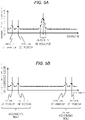
- Figs. 5A and 5B representing a relationship between a distance and the detected intensity of reflected or scattered light are obtained.
- the intensities of light reflected or scattered by the inside and outside of the protection window 123 and the object 300 to be measured are high as illustrated in Fig. 5A . Since intensity data is discrete with respect to a distance, the resolution of a distance is lowered in a case where only data on peaks are used. For this reason, in a case where at least three data points around each peak are selected and interpolation is performed, the resolution of a measured distance can be improved.
- a quadratic function is applied to the data on the three points around each peak to obtain the positions of apexes thereof, so that the interpolation of a distance is performed.
- a method of performing the interpolation of a distance by obtaining the centroids of data points exceeding a certain threshold can be employed.
- the intensity of reflected or scattered light may be used, the square root thereof may be used, and the logarithm thereof may also be used.
- a variation in the offset of a distance which is caused by the ranging device 101, thermal expansion caused by temperature between the optical fiber ends 120 and the reflective mirror 122, or the like, is included in a distance to be measured.
- the individual differences of the stiffness and mass of the rod and the measuring head are also related to a variation in the offset of a distance in addition to these.
- peaks caused by reflection and scattering on the surface of the protection window 123 of the measuring head are detected in addition to a distance to the object 300 to be measured and distances corresponding to the peaks are obtained and are deducted from the distance data on the object 300 to be measured. Accordingly, a distance from the surface of the protection window 123 can be accurately measured.
- the surfaces of the protection window are present at the inside and outside of the measuring head, that is, at two positions but the approximate positions thereof are determined in advance and are not significantly changed. Accordingly, in a case where the outside of the window is used as a reference (the outside of the window is used as a reference in this embodiment), the same interpolation processing as the object to be measured distance can be performed using measured data around the peak corresponding to this to calculate a reference distance. Antireflection coating corresponding to a specification wavelength may be performed only on the surface of the window, which is not used as a reference, to remove extra reflected light.
- the distance data on the surface of the window may be temporally averaged to improve the accuracy of the reference distance.
- a reference distance can be calculated while the inside of the window is used as a reference, but it is more preferable that the outside of the window is used as a reference since the position of the outside of the window can be accurately confirmed on the appearance of the measuring instrument 100.
- the other measuring head is detected as in Fig. 5B as illustrated by the measurement light 150' that is illustrated in Fig. 3 by a dotted line. Accordingly, in a case where this distance is calculated in the same manner as a manner that is used to obtain a distance to the surface of the window of the measuring head, a distance between the measuring heads 106 and 107 can be measured. A distance between the measuring heads 106 and 107 may be changed with time due to the deformation of the long rods 104 and 105 caused by environment, such as temperature.
- a distance S (which may also be referred to as correction processing) can be performed without the removal of the measuring instrument 100 from the machining apparatus 201, that is, the correction processing can be performed regardless of a mounting error and a detachment error of the measuring instrument 100.
- the distance S between the outer surfaces of the protection windows of the measuring head 106 for an outer periphery and the measuring head 107 for an inner periphery is obtained by ranging processing in a state where the object 300 to be measured is not present.
- a distance O between the outer surface of the protection window 123 of the measuring head 106 for an outer periphery and the outer peripheral surface of the object 300 to be measured is obtained by the measuring head 106 for an outer periphery.
- a distance between the rotation axis 210 and the outer surface of the protection window of the measuring head 107 for an inner periphery is denoted by ⁇ (since the measuring instrument 100 is moved in - z direction and the measuring head 107 for an inner periphery is inserted into the hole of the object 300 to be measured so that the center of the measuring head 107 for an inner periphery substantially coincides with the rotation axis 210, the approximate value of ⁇ is determined from the shape of the measuring head 107 for an inner periphery.)
- O( ⁇ ) and I( ⁇ ) are measured as a function of the rotation angle ⁇ while the object 300 to be measured is rotated about the rotation axis 210.
- T( ⁇ ) which can be calculated from this result, is thickness distribution.
- Oc( ⁇ ) and Ic( ⁇ ) are plotted in the polar coordinates, so that the cross-sectional shape of the outer periphery and the cross-sectional shape of the inner periphery are obtained. This aspect is illustrated in Fig. 7 .
- results measured on the cross-sections of (1), (2), and (3) illustrated in Fig. 1 are superimposed and illustrated in graphs (an example where a little difference is present in the shapes of three cross-sections is illustrated).
- Ic( ⁇ ), Oc( ⁇ ), and T( ⁇ ) may not be plotted in the polar coordinates just as they are and errors Ic( ⁇ ) -Io, Oc( ⁇ ) -Oo, and T( ⁇ ) -To from the reference distance may be plotted. These graphs may be displayed on a display of the measurement control device 102 to be easily understood by a user.
- a circle is fitted on the data on each of the inner diameter and the outer diameter of Fig. 7 so that the evaluation value of each error becomes minimum (the approximation of a circle using a least-square method), and the central position and the diameter of each circle are obtained.
- the eccentricity of each circle, the direction of the eccentricity, and the diameter of each circle are obtained.
- each of inner peripheral vibration and outer peripheral vibration can be calculated from a difference between the maximum value and the minimum value in one rotation of each of the inner and outer diameters.
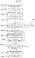
- Fig. 6 illustrates an example of the flow of the measurement processing of the measurement control device 102.
- the measurement control device 102 sets a cross-section number (A cross-section number means a number in parentheses representing a measurement position illustrated in Fig. 1 .
- the Z-coordinate of a cross-sectional position to be measured is defined for every cross-section number in advance.
- a position outside the object 300 to be measured is particularly defined as a cross-section number 0 to correct the distance S between the measuring heads.) to 0 first (S502).
- the measurement control device 102 controls the movement of the tool shaft or the tailstock 204 in -z direction to position the measuring heads 106 and 107 of the measuring instrument 100 at the position of (0). After positioning, the measurement control device 102 measures the distance S between the outer surfaces of the protection windows of the measuring head 106 for an outer periphery and the measuring head 107 for an inner periphery by the ranging device 101. The measurement control device 102 records the correction value of the distance S.
- the measurement control device 102 sets a cross-section number to 1.
- the measurement control device 102 controls the movement of the tool shaft or the tailstock 204 in -z direction to position the measuring heads 106 and 107 of the measuring instrument 100 at the position of a Z-coordinate that is defined in advance to correspond to the variable value of a cross-section number.
- the measurement control device 102 starts the constant-speed rotation of the spindle 202 of the machining apparatus 201.
- the measurement control device 102 records the distance O between the outer surface of the window of the measuring head 106 for an outer periphery and the outer peripheral surface of the object 300 to be measured and the distance I between the outer surface of the window of the measuring head 107 for an inner periphery and the inner peripheral surface of the object 300 to be measured, which are obtained from the ranging device 101, every predetermined sample time (or at an interval ⁇ of a predetermined rotation angle) so that the distances correspond to the rotation angle ⁇ of the spindle 202.
- the measurement control device 102 determines whether or not ( ⁇ ,O,I) data corresponding to one rotation of the spindle 202 is recorded whenever recording ( ⁇ ,O,I) in S507. If ( ⁇ ,O,I) data corresponding to one rotation of the spindle 202 is recorded, the measurement control device 102 ends the rotation of the spindle 202 and makes the measurement processing proceed to S509. If ( ⁇ ,O,I) data corresponding to one rotation of the spindle 202 is not yet recorded, the measurement control device 102 makes the measurement processing proceed to S507 again.
- the measurement control device 102 determines whether or not a cross-section number reaches the number N of cross-sections of which the measurement is scheduled (the measurement control device 102 determines whether or not measurement of one rotation ends on all of N scheduled cross-sections). If a cross-section number does not reach the number N of cross-sections of which the measurement is scheduled, the measurement control device 102 makes the measurement processing proceed to S510. If a cross-section number reaches the number N of cross-sections of which the measurement is scheduled, the measurement control device 102 makes the measurement processing proceed to S511.
- the measurement control device 102 increases a cross-section number by 1 and makes the measurement processing proceed to S505.
- the measurement control device 102 perform data processing for the distributions of the inner diameter, the outer diameter, and the thickness at the N cross-sectional positions of the object 300 to be measured on the basis of all the recorded ( ⁇ ,O,I) data of every cross-section and the correction value of the distance S; and outputs, for example, the graphs illustrated in Figs. 7 and 8 to a display device or the like.
- the measurement control device 102 ends the measurement processing.
- the measuring instrument 100 is moved in -Z direction by the tool shaft or the tailstock 204 of the machining apparatus 201 and performs measurement, but pitching or yawing slightly occurs ( ⁇ ) with the movement of the tool shaft or the tailstock 204 in -Z direction. Since the rods 104 and 105 holding the measuring heads 106 and 107 are long even though ⁇ is usually an inclination not causing a problem, the positions of the measuring heads 106 and 107 in a Y direction are slightly changed as exaggeratedly illustrated in Fig. 9 .
- the amount of change corresponds to L ⁇ in a case where the length of each of the rods 104 and 105 is denoted by L.
- L ⁇ is a displacement of 0.1 mm although, for example, ⁇ is 100 microradians.
- This aspect is illustrated in a graph on the lower side in Fig. 9 . Even though ⁇ is changed, thickness distribution, outer peripheral vibration/inner peripheral vibration, and the value of eccentricity are not affected but the measured values of the outer and inner diameters are affected. For this reason, an error is caused.
- the value of ⁇ is determined to be constant at every position in the Z direction.
- the touch probe is moved to positions of (1) to (N) in the Z direction where a cross-section is to be measured by the measuring instrument 100 of the invention, and performs measurement.
- ⁇ is measured at, for example, each of both ends of the object 300 to be measured by measurement using the touch probe and ⁇ at intermediate positions in the Z direction may be obtained from the linear interpolation of ⁇ obtained at the both ends of the object 300 to be measured.
- ⁇ is measured at each of three points, that is, both ends and the middle of the object 300 to be measured, and ⁇ at intermediate positions in the Z direction may be obtained from the measured ⁇ by the quadratic function interpolation.
- a measuring head which is similar to an inner/outer diameter measurement device and is formed of an optical non-contact displacement meter, may be prepared instead of the touch probe, may be held on the tool shaft 204 with a short distance like the touch probe 206, and may measure a distance instead of the touch probe.
- Oc is not measured by the touch probe
- a worker measures an outer diameter with a micrometer or the like
- the value of ⁇ may be determined so that the value of the outer diameter is equal to the value of an outer diameter, which is obtained in a case where a circle is fitted on corresponding Oc( ⁇ ) data in the Z-coordinate. That is, the value of ⁇ (the outer diameter measured with a micrometer)-(the outer diameter obtained from circle fitting) ⁇ /2 may be added to the value of ⁇ .
- ⁇ may be corrected at all the points (1) to (N).
- the value of ⁇ may be corrected at only both ends to reduce effort and interpolation may be performed, or ⁇ may be measured at three points, that is, both ends and the middle and ⁇ at intermediate positions in the Z direction may be obtained from the measured ⁇ by the quadratic function interpolation.
- ⁇ does not need to depend on a position on the Z axis
- an outer diameter or an inner diameter is measured at only one point and the value of ⁇ may be determined so that the measured value is equal to the value of the outer diameter or the inner diameter in a case where a circle is fitted.
- an offset of the measured value of the inner diameter/the outer diameter is corrected using the measurement result of another measuring instrument, such as a touch probe or a micrometer.
- another measuring instrument such as a touch probe or a micrometer.
- an embodiment where an offset of the measured value of the inner diameter/the outer diameter is corrected using the measuring instrument 100 is illustrated in Figs. 11A, 11B, 11C, 11D, and 11E .
- Fig. 11C illustrates a structure in the case of two sets thereof
- Fig. 11D illustrates a structure in the case of four sets thereof
- Fig. 11E illustrates a structure in the case of three sets thereof.
- Fig. 11A is a diagram illustrating the entire structure in the case of two sets thereof.
- one optical fiber 108 for an outer periphery and two optical fibers 108 for an inner periphery that is, optical fibers 108 of a total of three channels are relayed to connectors 109 and are connected to the ranging device 101 through optical fibers 110 of three channels.
- the numbers of the optical fibers 108 and 110 and the connectors 109 are increased as much as an increase in the number of pieces of measurement light 151' for an inner periphery.
- the connectors 109 and the optical fibers 110 are prepared as many as the number of pieces of measurement light in Fig. 11A , but it goes without saying that a connector and a cable capable of connecting a plurality of optical fiber channels may be used.
- the measured value of the inner diameter is obtained from the sum of the sum of the distance measurement values of measurement light 151 and 151' and a distance between the surfaces of the protection windows 123.
- the position of the measuring head 107 for an inner periphery in a horizontal direction (x direction) substantially coincides with the center of the inner periphery.
- measurement is performed while the measuring instrument 100 is moved in the horizontal direction (x direction) by a measuring instrument holder, the tool shaft, and the tailstock 204 so that measurement is performed at a position where the calculated value of the inner diameter is largest.
- the outer diameter can also be accurately calculated.
- a tool 290 is gripped by the tool shaft 204.
- the tool 290 may be a cutter (cutting tool) or may be a rotating tool. In a case where the cutting tool is used, machining is called turning. In a case where the rotating tool is used, machining is called turn milling.
- Fig. 12A schematically illustrates a case where the inner periphery a work (a hollow shaft in this example) 300 is eccentric to the outer periphery of the work upward, and the eccentricity of the inner periphery is increased toward the right side of the work.
- This state occurs in a case where the central axis of the inner periphery of the work does not coincide with the rotation axis 210 of the spindle 202 (the central axis of the outer periphery of the work) during the cutting of the outside of the work.
- a case where the work 300 is mounted on the spindle 202 again after the cutting of the inner periphery or another cutting method without the rotation of the spindle 202 is used is considered as one example of a cause.
- the eccentric state between the central axis of the outer periphery and the central axis of the inner periphery can be accurately measured on the machining apparatus 201.
- eccentricity which may include the direction of eccentricity
- machining can be performed according to the eccentricity of the inner periphery so that the axis of the inner periphery and the axis of the outer periphery are coaxial with each other (that is, the central axes coincide with each other). This example will be described.
- Fig. 12B illustrates a method of reducing eccentricity by performing eccentric turning or eccentric turn milling.
- the tool 290 machines a chuck face 310 while being moved in a vertical direction of Fig. 12B in synchronization with the angle of the spindle 202 so that the central axis of the chuck face 310 and the central axis of an inner peripheral surface corresponding to the chuck face 310 (an inner peripheral surface included in a cylinder in a case where the cylinder including the chuck face on a side surface is defined) coincide with each other (or eccentricity between the central axes is reduced).
- a work rest-receiving surface 311 is also machined likewise.
- the rotation axis of the spindle 202 and the central axis of the inner periphery can be made to coincide with each other.
- turning or turn milling is performed over the entire outer peripheral surface of the work 300.
- a hollow shaft 300 having high coaxiality of inner and outer peripheries can be produced by such an example .
- a machining apparatus 201 in this case is a machining apparatus that includes chuck mechanisms at both ends thereof.
- the adjustment distances of chucks 203 and 203' are adjusted so that the axis of an inner peripheral surface obtained by the measurement system of the invention coincides with the rotation axis 210, and the chucks are moved. In this state, turning or turn milling is performed over the entire outer peripheral surface of the work 300.
- a hollow shaft 300 having high coaxiality of inner and outer peripheries can also be produced by such an example .
- 201 denotes the machining apparatus, and the machining apparatus moves the measuring instrument 100 by the tool shaft or the tailstock 204 to insert the measuring instrument 100 into the object to be measured (a hollow shaft in the first embodiment) 300, and rotates the object to be measured by the turning shaft 202 to measure the object to be measured.
- the machining apparatus 201 may be formed as a dedicated measurement apparatus. In this case, as in a case where the machining apparatus is formed of a machining apparatus, the machining apparatus may move the measuring instrument 100 by the measuring instrument holder 204 to simultaneously realize the measurement of an inner diameter and an outer diameter.
- the machining apparatus may move the spindle 202 of an object to be measured in the Z direction without the movement of the measuring instrument 100 to measure each cross-section.
Landscapes
- Physics & Mathematics (AREA)
- General Physics & Mathematics (AREA)
- Optics & Photonics (AREA)
- Engineering & Computer Science (AREA)
- Mechanical Engineering (AREA)
- Length Measuring Devices By Optical Means (AREA)
- Machine Tool Sensing Apparatuses (AREA)
Description
- The present invention relates to a method and system for measuring an object that is a shaft with a hole, such as a hollow (also referred to as a through-hole) shaft or a shaft with a blind hole, and a method of manufacturing the object.
- In the past, ends of the shaft could be measured with a micrometer or the like in a case where the axis of the inner periphery of a hollow shaft or a shaft with a blind hole and the axis of the outer periphery thereof need to accurately coincide with each other. However, since a measuring instrument cannot enter the middle portion of the shaft, an effort to measure a thickness with ultrasonic waves has been required to measure the degree of coincidence of axes.
- There is a device disclosed in
JP 2013-164273 A - In
JP 2013-164273 A - Meanwhile, since the propagation speed of ultrasonic waves is changed due to a variation in material in a technique as the method in the related art that applies ultrasonic waves from the outer periphery and directly measures a thickness from the propagation time of ultrasonic waves reflected on the inner periphery, there is a problem that the technique has an error of an order of 0.1 mm. In addition, since the surface of a material needs to be smoothly machined to apply ultrasonic waves to the material, there is also a problem that an additional process is required to measure a thickness.
-
EP 3 351 894 A1EP 2 905 576 A1 - The invention has been made in consideration of the above-mentioned circumstances, and an object of the invention is to provide a system that can accurately measure the thickness of a shaft with a hole, and a method of manufacturing a shaft with a hole. Other objects of the invention will become clear in embodiments.
- The measurement system of the present invention is defined in
Claim 1. The manufacturing method of the present invention is defined in claim 6. - According to the invention, it is possible to provide a system that can accurately measure the thickness of a shaft with a hole, and a method of manufacturing a shaft with a hole.
-
-
Fig. 1 is a diagram illustrating the structure of a measurement system of the invention; -
Fig. 2 is an enlarged view of a measuring head unit of the measurement system of the invention; -
Fig. 3 is an enlarged view illustrating a non-claimed example of a structure of a measuring head unit of a measurement system; -
Fig. 4 is a diagram illustrating the definition of various distances between the measuring head unit of the measurement system and a work; -
Figs. 5A and 5B are diagrams illustrating examples of the output data of a ranging device of the invention; -
Fig. 6 is a diagram illustrating the flow of a measurement operation of the invention; -
Fig. 7 is a diagram illustrating an example of an analysis/display method for the distributions of an inner diameter, an external form, and a thickness of the invention; -
Fig. 8 is a diagram illustrating another example of the analysis/display method for the distributions of an inner diameter, an external form, and a thickness of the invention; -
Fig. 9 is a diagram illustrating a problem in a case where an inner diameter and an outer diameter are to be measured in the measurement system of the invention; -
Fig. 10 is a diagram illustrating an embodiment where a touch probe is used together to accurately obtain an inner diameter and an outer diameter in the measurement system of the invention; -
Figs. 11A, 11B, 11C, 11D and 11E are diagrams illustrating an embodiment where additional measurement light is added in a measuring head for an inner periphery to accurately obtain an inner diameter and an outer diameter in the measurement system of the invention; and -
Figs. 12A, 12B, and 12C are diagrams illustrating an example of a method of machining an outer periphery by using the measurement result of the measurement system of the invention. - Embodiments and examples will be described below with reference to the drawings. Meanwhile, a hollow shaft, which includes a through-hole therein, will be described in the following embodiments by way of example, but objects to be measured including other holes, such as a blind hole, may also be used as an object.
-
Fig. 1 illustrates the entire structure of a measurement system of the invention that is installed on amachining apparatus 201. The measurement system is a system that includes ameasuring instrument 100, a rangingdevice 101, and ameasurement control device 102. Meanwhile, themeasuring instrument 100 includes measuringheads rods measuring instrument base 103 as described later. The rangingdevice 101 generates measurement light, and sends the measurement light toconnectors 109 of themeasuring instrument base 103 through twooptical fibers 110. Themeasuring instrument base 103 sends the measurement light to themeasuring heads optical fibers 108. Themeasuring head 106 is a measuring head for an outer periphery, and themeasuring head 107 is a measuring head for an inner periphery. Themeasuring heads object 300 to be measured (an example of the cross-section of a hollow shaft is illustrated inFig. 1 ) with the measurement light, respectively; condense light, which is reflected by theobject 300 to be measured and returns, again; and make the condensed light return to the rangingdevice 101 through theoptical fibers 108, theconnectors 109, and theoptical fibers 110. - The
measuring head 106 for an outer periphery is held on themeasuring instrument base 103 by therod 104 for an outer periphery and themeasuring head 107 for an inner periphery is held on themeasuring instrument base 103 by therod 105 for an inner periphery, so that onemeasuring instrument 100 is formed as a whole. Themeasuring instrument 100 is mounted on a tool shaft (a carriage that holds a cutter and is moved) or atailstock 204 of the machining apparatus 201 (for example, a lathe) and is horizontally held. For example, a hollow shaft, which is theobject 300 to be measured, is mounted on a spindle (turning shaft) 202 of themachining apparatus 201 through achuck 203. Theobject 300 to be measured may be supported from below and the left and right sides by awork rest 205 as necessary. Meanwhile, in a case where themachining apparatus 201 is a lathe including a cutter holder, themeasuring instrument 100 may be mounted on the cutter holder. A case where the measuring instrument is mounted on thetailstock 204 will be described in the following description. - The positions of the
measuring instrument 100 in an x direction and a y direction ofFig. 1 are adjusted by the tool shaft or thetailstock 204 so that arotation axis 210 of thespindle 202 of the machining apparatus 201 (hereinafter, simply referred to as a rotation axis 210) and the center of themeasuring head 107 for an inner periphery (the center of the xy cross-section of themeasuring head 107 for an inner periphery to be inserted into the inner peripheral portion of theobject 300 to be measured) substantially coincide with each other. Themeasuring instrument 100 is further moved in - z direction ofFig. 1 by the tool shaft or thetailstock 204, so that themeasuring head 107 for an inner periphery is inserted into theobject 300 to be measured and themeasuring head 106 for an outer periphery is inserted to the outside of theobject 300 to be measured while avoiding thework rest 205. - In a state where the
measuring head 106 for an outer periphery and themeasuring head 107 for an inner periphery are inserted up to an appropriate position of theobject 300 to be measured, theobject 300 to be measured is rotated by the rotation of thespindle 202. Distances to the outer peripheral surface and the inner peripheral surface of theobject 300 to be measured are measured during the rotation by themeasuring head 106 for an outer periphery and themeasuring head 107 for an inner periphery, so that the measurement of the angular distributions of an inner diameter deviation, an outer diameter deviation, and a thickness at the position can be realized. At this time, in a case where positions where a user wants to measure theobject 300 to be measured are present at N cross-sections, the above-mentioned operation may be performed at positions corresponding to numbers in parentheses, that is, (1), (2), (3), ···, (N) illustrated inFig. 1 in a state where the heads are inserted. - Here, the control of the machining apparatus 201 (for example, the position (more specifically, the rotation angle) of the hollow shaft and the position of the tailstock) is performed by an NC (numerical control)
control device 220. While monitoring the position data on each shaft of themachining apparatus 201 obtained from theNC control device 220, themeasurement control device 102 receives measured distance data, which is measured by and output from the rangingdevice 101, and performs measurement data processing. The rotation angle of the hollow shaft may be manually changed by a worker or the position of themeasuring instrument 100 may be changed, but measurement accuracy is further improved in a case where the stable operation of theNC control device 220 is used. Further, NC data for correction/finish machining can be generated on the basis of measured data, such as the eccentricities of the internal form and the external form, which are obtained from themeasurement control device 102. - According to the invention, the methods mentioned below can be utilized as a method of measuring a distance. One of them is a method of measuring time that is required in a case where light is applied to an object to be measured and returns. The method of measuring a distance may include OCT (Optical Coherence Tomography) or FMCW (Frequency Modulated Continuous Wave). In addition, a method of measuring time having passed until a pulse or burst light is received after the application of the pulse or burst light, such as a TOF (Time Of Flight) method, and methods of measuring the phase of a received signal after the application of continuously intensity-modulated light, such as a phase shift method and a ranging method using optical frequency combs, can be used as the method of measuring a distance according to the invention.
- In non-claimed examples, there is also a method of measuring defocus. An astigmatic focus error detection method, a knife edge method, and a conoscopic holography method can be used in addition to a confocal method with white light source to be described later in further non-claimed examples.
- In other non-claimed examples, there is also a so-called light stripe triangulation method of irradiating an object with laser light and obliquely measuring the position of a point, which shines on the surface of the object by scattering, to measure a distance by triangulation.
- The measuring
head 106 for an outer periphery and the measuringhead 107 for an inner periphery will be described in detail below with reference toFig. 2 . Light, which is sent from eachoptical fiber 108, is emitted to a space from anoptical fiber end 120. The emitted light is converted into condensed light by alens 121. This light is bent by areflective mirror 122, and is applied to theobject 300 to be measured through aprotection window 123. Light, which is reflected or scattered by the surface of the object to be measured, returns to theprotection window 123, thereflective mirror 122, and thelens 121 along an original optical path, and returns to theoptical fiber 108 from theoptical fiber end 120. The above description is commonly applied tomeasurement light 150 of the measuringhead 106 for an outer periphery andmeasurement light 151 of the measuringhead 107 for an inner periphery. Meanwhile, since thereflective mirror 122 is employed, theoptical fiber 108 extending from theoptical fiber end 120 is made to extend substantially parallel to therod 104 and does not need to be bent. As a result, since the heights of the measuringhead 106 for an outer periphery and the measuringhead 107 for an inner periphery can be made small, a hollow shaft including a hole having a small diameter can be measured. In non-claimed examples, the reflective mirror may be omitted and theoptical fiber 108 may be bent so that light is applied from theoptical fiber end 120 in a vertical direction in the plane of paper. - Here, in the first embodiment, a lens for laser can be used as the
lens 121, laser can be used as the measurement light, and one of OCT, FMCW, TOF, a phase shift method, or a ranging method using optical frequency combs is used to detect a change in the position of the surface of theobject 300 to be measured as a distance. - In a non-claimed case where a lens having a large chromatic aberration is used as the
lens 121 and broadband light is used as the measurement light as another method, a focal length varies depending on a wavelength and light, which returns to the rangingdevice 101 from theoptical fiber end 120 again, of the measurement light applied to theobject 300 to be measured is light having a wavelength component exactly focused on the surface of a work. The ranging device is formed of a spectroscope to detect the wavelength of returning light, so that a distance can be obtained. - Further, still another non-claimed method of measuring a distance will be described with reference to
Fig. 3 . Each of the measuringhead 106 for an outer periphery and the measuringhead 107 for an inner periphery has the following internal structure. Light emitted from a high-brightnesslight emitting element 140, such as a laser diode, is converted into convergent light by a lens 141 and is applied to anobject 300 to be measured asmeasurement light object 300 to be measured, is condensed by alens 142 and forms an image on alinear image sensor 143. Since an image-formation position is changed depending on a distance to a position where light is applied to theobject 300 to be measured, a distance can be measured. - Measurement light 150' for an outer periphery in a case where the
object 300 to be measured is not present is illustrated inFig. 3 by a dotted line. As illustrated inFig. 3 , in a case where theobject 300 to be measured is not present, the measurement light 150' is scattered by the surface of theprotection window 123 of the measuringhead 107 for an inner periphery, travels along apath 152 illustrated by a dotted line, and forms an image on thelinear image sensor 143. Accordingly, an image-formation position on thelinear image sensor 143, which faces the lower left side inFig. 3 , is shifted to the left side. A method of measuring a distance using the principle of triangulation in this way is generally called a light stripe triangulation method. Meanwhile, in the case of this non-claimed structure, members, which connect the rangingdevice 101 to the measuring heads 106 and 107, are not theoptical fibers light emitting elements 140 and drive/readout signals of thelinear image sensor 143 are transmitted and received through electric wires 108' instead. - Since all the above-mentioned methods of measuring a distance can measure a distance with light in a non-contact manner, the measuring heads held by the
elongated rods narrow object 300 to be measured. - The positions of the inner peripheral surface and the outer peripheral surface of an elongated object to be measured (hollow shaft) could be simultaneously measured from the inside and outside by the above-mentioned structure. Meanwhile, the measuring heads 106 and 107 can be made light and compact as described above but the
rods rods heads Fig. 2 will be described in the first embodiment and a second embodiment and other embodiments to be described later by way of example or as the basis of expansion. However, the first embodiment and a second embodiment and other embodiments to be described later may, in non-claimed examples, employ the measuring heads 106 and 107 illustrated inFig. 3 or measuringheads - Various configurations are considered as the hardware configuration of the ranging
device 101 on the basis of a difference in the above-mentioned methods of measuring a distance. Meanwhile, in a case where light is sent to the measuring heads 106 and 107 through optical fibers as inFig. 2 and the like, the rangingdevice 101 includes a laser light source. Although not illustrated, laser light generated from a laser light source is divided by a half mirror and one part of the laser light passes through the optical fiber and the measuring head, is reflected by the object to be measured, and returns to the rangingdevice 101 again in a case where, for example, OCT is employed. The other part of the laser light is reflected by a reference mirror, is superimposed on the returning laser light, and an interference beat signal is taken by a photodetector. AD conversion is performed; a distance is converted from the frequency of the beat signal (in other words, a distance is measured) by a logic function provided on, for example, FPGA; and distance data is output to themeasurement control device 102. - The hardware configuration of the
measurement control device 102 is not illustrated, but a general-purpose computer including a processor (CPU), a memory, an auxiliary storage device, an input device, an output device, and a communication interface is used. A plurality of functions for processing for optically measuring the shapes of the inner and outer peripheries of a hollow shaft or a shaft with a blind hole and processing for generating NC data for correction/finish machining used to finish a shaft having high coaxiality of an inner periphery and an outer periphery are realized by the execution of a program stored in the auxiliary storage device. Meanwhile, a configuration where the respective functions realized by the processor (CPU) and the memory are dispersed in a plurality of integrated circuits or a configuration where a dedicated electronic circuit (DSP) realizes each function can also be employed. Meanwhile, the measurement control device may be theNC control device 220 or may be other device as illustrated inFig. 1 . Themeasurement control device 102 may transmit an instruction to change the rotation angle or the number of rotation of thespindle 202 and an instruction to change the position of thetailstock 204 for the change of the position of the measuringinstrument 100 to theNC control device 220, as some kinds of processing that is required to perform the processing. Further, the measurement control device may transmit these instructions to a worker (for example, the display of these instructions or the transmission of a mail is considered). - In addition, the signal processing of the ranging
device 101 will be described with reference toFigs. 5A and 5B . Even though any of the above-mentioned measurement principles is used, data illustrated inFigs. 5A and 5B representing a relationship between a distance and the detected intensity of reflected or scattered light are obtained. The intensities of light reflected or scattered by the inside and outside of theprotection window 123 and theobject 300 to be measured are high as illustrated inFig. 5A . Since intensity data is discrete with respect to a distance, the resolution of a distance is lowered in a case where only data on peaks are used. For this reason, in a case where at least three data points around each peak are selected and interpolation is performed, the resolution of a measured distance can be improved. For example, a quadratic function is applied to the data on the three points around each peak to obtain the positions of apexes thereof, so that the interpolation of a distance is performed. Alternatively, a method of performing the interpolation of a distance by obtaining the centroids of data points exceeding a certain threshold can be employed. Further, as the data point, the intensity of reflected or scattered light may be used, the square root thereof may be used, and the logarithm thereof may also be used. - Furthermore, a variation in the offset of a distance, which is caused by the ranging
device 101, thermal expansion caused by temperature between the optical fiber ends 120 and thereflective mirror 122, or the like, is included in a distance to be measured. Meanwhile, the individual differences of the stiffness and mass of the rod and the measuring head are also related to a variation in the offset of a distance in addition to these. To cope with these, peaks caused by reflection and scattering on the surface of theprotection window 123 of the measuring head are detected in addition to a distance to theobject 300 to be measured and distances corresponding to the peaks are obtained and are deducted from the distance data on theobject 300 to be measured. Accordingly, a distance from the surface of theprotection window 123 can be accurately measured. The surfaces of the protection window are present at the inside and outside of the measuring head, that is, at two positions but the approximate positions thereof are determined in advance and are not significantly changed. Accordingly, in a case where the outside of the window is used as a reference (the outside of the window is used as a reference in this embodiment), the same interpolation processing as the object to be measured distance can be performed using measured data around the peak corresponding to this to calculate a reference distance. Antireflection coating corresponding to a specification wavelength may be performed only on the surface of the window, which is not used as a reference, to remove extra reflected light. Further, since the position of the window, which corresponds to a reference distance, is not suddenly changed, the distance data on the surface of the window may be temporally averaged to improve the accuracy of the reference distance. Meanwhile, a reference distance can be calculated while the inside of the window is used as a reference, but it is more preferable that the outside of the window is used as a reference since the position of the outside of the window can be accurately confirmed on the appearance of the measuringinstrument 100. - Furthermore, in a case where the
object 300 to be measured is not present, the other measuring head is detected as inFig. 5B as illustrated by the measurement light 150' that is illustrated inFig. 3 by a dotted line. Accordingly, in a case where this distance is calculated in the same manner as a manner that is used to obtain a distance to the surface of the window of the measuring head, a distance between the measuringheads heads long rods heads hollow shaft 300, which is an object to be measured, at a position indicated by a number in parentheses, that is, (0) illustrated inFig. 1 before the measurement of the object to be measured, an error in a thickness to be measured, which is caused by a change in the distance between the measuringheads instrument 100 from themachining apparatus 201, that is, the correction processing can be performed regardless of a mounting error and a detachment error of the measuringinstrument 100. - Next, the ranging processing will be described in detail with reference to
Fig. 4 . The distance S between the outer surfaces of the protection windows of the measuringhead 106 for an outer periphery and the measuringhead 107 for an inner periphery is obtained by ranging processing in a state where theobject 300 to be measured is not present. In regard to ranging data in a state where the object to be measured is present, a distance O between the outer surface of theprotection window 123 of the measuringhead 106 for an outer periphery and the outer peripheral surface of theobject 300 to be measured is obtained by the measuringhead 106 for an outer periphery. Further, a distance I between the outer surface of theprotection window 123 of the measuringhead 107 for an inner periphery and the inner peripheral surface of theobject 300 to be measured is obtained by the measuringhead 107 for an inner periphery. Accordingly, a thickness T to be measured of theobject 300 to be measured can be calculated from "T = S - O - I". In a case where a distance between therotation axis 210 and the outer surface of the protection window of the measuringhead 107 for an inner periphery is denoted by Δ (since the measuringinstrument 100 is moved in - z direction and the measuringhead 107 for an inner periphery is inserted into the hole of theobject 300 to be measured so that the center of the measuringhead 107 for an inner periphery substantially coincides with therotation axis 210, the approximate value of Δ is determined from the shape of the measuringhead 107 for an inner periphery.), a distance Ic between therotation axis 210 and the inner peripheral surface of theobject 300 to be measured can be calculated from "Ic = I + Δ" and a distance Oc between therotation axis 210 and the outer peripheral surface of theobject 300 to be measured can be calculated from "Oc = S + Δ - O". - O(θ) and I(θ) are measured as a function of the rotation angle θ while the
object 300 to be measured is rotated about therotation axis 210. T(θ), which can be calculated from this result, is thickness distribution. Oc(θ) and Ic(θ) are plotted in the polar coordinates, so that the cross-sectional shape of the outer periphery and the cross-sectional shape of the inner periphery are obtained. This aspect is illustrated inFig. 7 . In this example, results measured on the cross-sections of (1), (2), and (3) illustrated inFig. 1 are superimposed and illustrated in graphs (an example where a little difference is present in the shapes of three cross-sections is illustrated). Meanwhile, in order to emphasize errors, Ic(θ), Oc(θ), and T(θ) may not be plotted in the polar coordinates just as they are and errors Ic(θ) -Io, Oc(θ) -Oo, and T(θ) -To from the reference distance may be plotted. These graphs may be displayed on a display of themeasurement control device 102 to be easily understood by a user. - A circle is fitted on the data on each of the inner diameter and the outer diameter of
Fig. 7 so that the evaluation value of each error becomes minimum (the approximation of a circle using a least-square method), and the central position and the diameter of each circle are obtained. As a result, the eccentricity of each circle, the direction of the eccentricity, and the diameter of each circle are obtained. Further, each of inner peripheral vibration and outer peripheral vibration can be calculated from a difference between the maximum value and the minimum value in one rotation of each of the inner and outer diameters. - Furthermore, the central positions of the circles of the respective cross-sections obtained above are plotted so that a horizontal axis represents the coordinate of a cross-section [(1), (2), (3), ···] and a vertical axis represents the X-coordinate or the Y-coordinate of the central position. As a result, the graphs of
Fig. 8 are obtained. It is possible to see a state where the inner peripheral surface and the outer peripheral surface are eccentric and tilted form the graphs. These graphs may be displayed on the display of themeasurement control device 102 to be easily understood by a user. -
Fig. 6 illustrates an example of the flow of the measurement processing of themeasurement control device 102. - In a case where measurement is started (S501), the
measurement control device 102 sets a cross-section number (A cross-section number means a number in parentheses representing a measurement position illustrated inFig. 1 . The Z-coordinate of a cross-sectional position to be measured is defined for every cross-section number in advance. A position outside theobject 300 to be measured is particularly defined as across-section number 0 to correct the distance S between the measuring heads.) to 0 first (S502). - In S503, the
measurement control device 102 controls the movement of the tool shaft or thetailstock 204 in -z direction to position the measuring heads 106 and 107 of the measuringinstrument 100 at the position of (0). After positioning, themeasurement control device 102 measures the distance S between the outer surfaces of the protection windows of the measuringhead 106 for an outer periphery and the measuringhead 107 for an inner periphery by the rangingdevice 101. Themeasurement control device 102 records the correction value of the distance S. - In S504, the
measurement control device 102 sets a cross-section number to 1. - In S505, the
measurement control device 102 controls the movement of the tool shaft or thetailstock 204 in -z direction to position the measuring heads 106 and 107 of the measuringinstrument 100 at the position of a Z-coordinate that is defined in advance to correspond to the variable value of a cross-section number. - In S506, the
measurement control device 102 starts the constant-speed rotation of thespindle 202 of themachining apparatus 201. - In S507, the
measurement control device 102 records the distance O between the outer surface of the window of the measuringhead 106 for an outer periphery and the outer peripheral surface of theobject 300 to be measured and the distance I between the outer surface of the window of the measuringhead 107 for an inner periphery and the inner peripheral surface of theobject 300 to be measured, which are obtained from the rangingdevice 101, every predetermined sample time (or at an interval δ of a predetermined rotation angle) so that the distances correspond to the rotation angle θ of thespindle 202. - In S508, the
measurement control device 102 determines whether or not (θ,O,I) data corresponding to one rotation of thespindle 202 is recorded whenever recording (θ,O,I) in S507. If (θ,O,I) data corresponding to one rotation of thespindle 202 is recorded, themeasurement control device 102 ends the rotation of thespindle 202 and makes the measurement processing proceed to S509. If (θ,O,I) data corresponding to one rotation of thespindle 202 is not yet recorded, themeasurement control device 102 makes the measurement processing proceed to S507 again. - In S509, the
measurement control device 102 determines whether or not a cross-section number reaches the number N of cross-sections of which the measurement is scheduled (themeasurement control device 102 determines whether or not measurement of one rotation ends on all of N scheduled cross-sections). If a cross-section number does not reach the number N of cross-sections of which the measurement is scheduled, themeasurement control device 102 makes the measurement processing proceed to S510. If a cross-section number reaches the number N of cross-sections of which the measurement is scheduled, themeasurement control device 102 makes the measurement processing proceed to S511. - In S510, the
measurement control device 102 increases a cross-section number by 1 and makes the measurement processing proceed to S505. - In S511, the
measurement control device 102 perform data processing for the distributions of the inner diameter, the outer diameter, and the thickness at the N cross-sectional positions of theobject 300 to be measured on the basis of all the recorded (θ,O,I) data of every cross-section and the correction value of the distance S; and outputs, for example, the graphs illustrated inFigs. 7 and 8 to a display device or the like. - In S512, the
measurement control device 102 ends the measurement processing. - Next, an embodiment where the values of inner and outer diameters are more accurately will be described with reference to
Figs. 9 and 10 . The measuringinstrument 100 is moved in -Z direction by the tool shaft or thetailstock 204 of themachining apparatus 201 and performs measurement, but pitching or yawing slightly occurs (α) with the movement of the tool shaft or thetailstock 204 in -Z direction. Since therods Fig. 9 . The amount of change corresponds to Lα in a case where the length of each of therods rotation axis 210 and the surface of theprotection window 123 of the measuringhead 107 for an inner periphery defined inFig. 4 is changed with the movement of the tool shaft or thetailstock 204 in -z direction. This aspect is illustrated in a graph on the lower side inFig. 9 . Even though Δ is changed, thickness distribution, outer peripheral vibration/inner peripheral vibration, and the value of eccentricity are not affected but the measured values of the outer and inner diameters are affected. For this reason, an error is caused. - Accordingly, a method of correcting Δ by another method as illustrated in
Fig. 10 has been devised. Here, a touch probe 206 (a touch probe is adapted to output a position on a space at the time when a gauge head touches an object to be measured.) is held on thetool shaft 204 instead of the measuringinstrument 100. Accordingly, the position of the outer peripheral surface of theobject 300 to be measured is measured, and Δ may be determined so that this value is equal to the position (Oc = S + Δ - O) of the outer peripheral surface of theobject 300 to be measured, which is defined inFig. 4 and measured by the measuringhead 106 for an outer periphery. Since the values of S and O are known, the value of Δ is determined to be constant at every position in the Z direction. Preferably, the touch probe is moved to positions of (1) to (N) in the Z direction where a cross-section is to be measured by the measuringinstrument 100 of the invention, and performs measurement. - In a case where a change in Δ is small during the movement of the
tool shaft 204 in -Z direction, for example, Δ is measured at, for example, each of both ends of theobject 300 to be measured by measurement using the touch probe and Δ at intermediate positions in the Z direction may be obtained from the linear interpolation of Δ obtained at the both ends of theobject 300 to be measured. Alternatively, Δ is measured at each of three points, that is, both ends and the middle of theobject 300 to be measured, and Δ at intermediate positions in the Z direction may be obtained from the measured Δ by the quadratic function interpolation. In addition, in a case where measurement accuracy where a change in Δ needs to depend on the measurement position on a Z axis is low, only the value of Δ not depending on the position in the Z direction, such as the deformation of therod 104 for an outer periphery and therod 105 for an inner periphery of the measuringinstrument 100 with time and a variation in the grip of the measuringinstrument 100 using the tool shaft or thetailstock 204, may be corrected. In this case, measurement using the touch probe may be performed at only one point on the outer periphery of theobject 300 to be measured. Alternatively, the inner peripheral surface of theobject 300 to be measured is touched by the touch probe at a position close to the end portion of theobject 300 to be measured illustrated at (1) inFig. 1 , and the value of Δ may be determined so that this position is equal to "Ic = I + Δ". - Measurement for the correction of Δ has been performed by the
touch probe 206 above. However, as another embodiment, a measuring head, which is similar to an inner/outer diameter measurement device and is formed of an optical non-contact displacement meter, may be prepared instead of the touch probe, may be held on thetool shaft 204 with a short distance like thetouch probe 206, and may measure a distance instead of the touch probe. - Alternatively, as another embodiment, Oc is not measured by the touch probe, a worker measures an outer diameter with a micrometer or the like, and the value of Δ may be determined so that the value of the outer diameter is equal to the value of an outer diameter, which is obtained in a case where a circle is fitted on corresponding Oc(θ) data in the Z-coordinate. That is, the value of {(the outer diameter measured with a micrometer)-(the outer diameter obtained from circle fitting) }/2 may be added to the value of Δ. Δ may be corrected at all the points (1) to (N). However, the value of Δ may be corrected at only both ends to reduce effort and interpolation may be performed, or Δ may be measured at three points, that is, both ends and the middle and Δ at intermediate positions in the Z direction may be obtained from the measured Δ by the quadratic function interpolation. Alternatively, in a case where Δ does not need to depend on a position on the Z axis, an outer diameter or an inner diameter is measured at only one point and the value of Δ may be determined so that the measured value is equal to the value of the outer diameter or the inner diameter in a case where a circle is fitted.
- In the second embodiment, an offset of the measured value of the inner diameter/the outer diameter is corrected using the measurement result of another measuring instrument, such as a touch probe or a micrometer. However, an embodiment where an offset of the measured value of the inner diameter/the outer diameter is corrected using the measuring
instrument 100 is illustrated inFigs. 11A, 11B, 11C, 11D, and 11E . - Two or more sets of
optical fibers 108, optical fiber ends 120,lenses 121, mirrors 122, andprotection windows 123 of the measuringhead 107 for an inner periphery are provided so that additional measurement light 151' can be radially emitted.Fig. 11C illustrates a structure in the case of two sets thereof,Fig. 11D illustrates a structure in the case of four sets thereof, andFig. 11E illustrates a structure in the case of three sets thereof. -
Fig. 11A is a diagram illustrating the entire structure in the case of two sets thereof. In this case, oneoptical fiber 108 for an outer periphery and twooptical fibers 108 for an inner periphery, that is,optical fibers 108 of a total of three channels are relayed toconnectors 109 and are connected to the rangingdevice 101 throughoptical fibers 110 of three channels. The numbers of theoptical fibers connectors 109 are increased as much as an increase in the number of pieces of measurement light 151' for an inner periphery. Meanwhile, theconnectors 109 and theoptical fibers 110 are prepared as many as the number of pieces of measurement light inFig. 11A , but it goes without saying that a connector and a cable capable of connecting a plurality of optical fiber channels may be used. - In the case of
Fig. 11C , the measured value of the inner diameter is obtained from the sum of the sum of the distance measurement values ofmeasurement light 151 and 151' and a distance between the surfaces of theprotection windows 123. In this case, it is premised that the position of the measuringhead 107 for an inner periphery in a horizontal direction (x direction) substantially coincides with the center of the inner periphery. In a case where an error of the measured value of the inner diameter caused by the shift of the central position cannot be ignored, measurement is performed while the measuringinstrument 100 is moved in the horizontal direction (x direction) by a measuring instrument holder, the tool shaft, and thetailstock 204 so that measurement is performed at a position where the calculated value of the inner diameter is largest. - In the cases of
Figs. 11D and 11E , data, which is obtained from the sum of the distance measurement value of each measurement light (151, 151') and a radial distance between the surface of theprotection window 123 and the center of the measuringhead 107 for an inner periphery, are obtained as many as the number of pieces of the measurement light. That is, the direction of each measurement light and a radial distance between the center of the measuring head and a position where the inner periphery is irradiated with measurement light are obtained. In a case where a circle is fitted on these data plotted in the polar coordinates, the value of the inner diameter is accurately obtained. - The values of the inner diameter at the respective measurement positions (1), (2), ···, (N), which are obtained in this way, can be used to determine the value of Δ so that the radius of the inner diameter is equal to "Ic = I + Δ". In a case where the outer diameter is calculated from the measured data of the measuring
head 106 for an outer periphery by using this value, the outer diameter can also be accurately calculated. - Next, an example of machining, which utilizes the measurement result of the measurement system of the invention, will be described with reference to
Figs. 12A, 12B, and 12C . Components common to the components described inFig. 1 are not illustrated but atool 290 is gripped by thetool shaft 204. Thetool 290 may be a cutter (cutting tool) or may be a rotating tool. In a case where the cutting tool is used, machining is called turning. In a case where the rotating tool is used, machining is called turn milling. -
Fig. 12A schematically illustrates a case where the inner periphery a work (a hollow shaft in this example) 300 is eccentric to the outer periphery of the work upward, and the eccentricity of the inner periphery is increased toward the right side of the work. This state occurs in a case where the central axis of the inner periphery of the work does not coincide with therotation axis 210 of the spindle 202 (the central axis of the outer periphery of the work) during the cutting of the outside of the work. A case where thework 300 is mounted on thespindle 202 again after the cutting of the inner periphery or another cutting method without the rotation of thespindle 202 is used is considered as one example of a cause. In a case where the measurement system of the invention is used, the eccentric state between the central axis of the outer periphery and the central axis of the inner periphery (for example, eccentricity (which may include the direction of eccentricity)) can be accurately measured on themachining apparatus 201. Generally, most of hollow shaft components and shaft components with blind holes need to be machined without such eccentricity. In a case where the invention is used, machining can be performed according to the eccentricity of the inner periphery so that the axis of the inner periphery and the axis of the outer periphery are coaxial with each other (that is, the central axes coincide with each other). This example will be described. -
Fig. 12B illustrates a method of reducing eccentricity by performing eccentric turning or eccentric turn milling. Thetool 290 machines achuck face 310 while being moved in a vertical direction ofFig. 12B in synchronization with the angle of thespindle 202 so that the central axis of thechuck face 310 and the central axis of an inner peripheral surface corresponding to the chuck face 310 (an inner peripheral surface included in a cylinder in a case where the cylinder including the chuck face on a side surface is defined) coincide with each other (or eccentricity between the central axes is reduced). A work rest-receiving surface 311 is also machined likewise. Next, in a case where thechuck face 310 is gripped by thechuck 203 and the work rest-receiving surface 311 is received by thework rest 205, the rotation axis of thespindle 202 and the central axis of the inner periphery can be made to coincide with each other. In this state, turning or turn milling is performed over the entire outer peripheral surface of thework 300. Ahollow shaft 300 having high coaxiality of inner and outer peripheries can be produced by such an example. - Next, another example, which produces a shaft having high coaxiality of inner and outer peripheries, will be described with reference to
Fig. 12C . Amachining apparatus 201 in this case is a machining apparatus that includes chuck mechanisms at both ends thereof. The adjustment distances ofchucks 203 and 203' are adjusted so that the axis of an inner peripheral surface obtained by the measurement system of the invention coincides with therotation axis 210, and the chucks are moved. In this state, turning or turn milling is performed over the entire outer peripheral surface of thework 300. Ahollow shaft 300 having high coaxiality of inner and outer peripheries can also be produced by such an example. - Meanwhile, in both the examples of
Figs. 12B and 12C , it goes without saying that the chuck face and the work rest-receiving surface, of which the outer peripheries are not yet machined, need to be finally subjected to finish machining. - In the description of
Fig. 1 of the first embodiment, 201 denotes the machining apparatus, and the machining apparatus moves the measuringinstrument 100 by the tool shaft or thetailstock 204 to insert the measuringinstrument 100 into the object to be measured (a hollow shaft in the first embodiment) 300, and rotates the object to be measured by the turningshaft 202 to measure the object to be measured. However, as another embodiment, themachining apparatus 201 may be formed as a dedicated measurement apparatus. In this case, as in a case where the machining apparatus is formed of a machining apparatus, the machining apparatus may move the measuringinstrument 100 by the measuringinstrument holder 204 to simultaneously realize the measurement of an inner diameter and an outer diameter. However, as another structure, the machining apparatus may move thespindle 202 of an object to be measured in the Z direction without the movement of the measuringinstrument 100 to measure each cross-section.
Claims (6)
- A measurement system for measuring a distance from an object (300) to be measured including a hole and fixed to a spindle (202) of a machining apparatus (201), the measurement system comprising:a measuring instrument (100);a measurement control device (102); anda ranging device (101) connected to the measurement control device,wherein the measuring instrument includes a base (103) to be fixed to a tool shaft, a cutter holder, or a tailstock (204) of the machining apparatus, a first rod (105) connected to the base, a second rod (104) connected to the base, a first measuring head (107) fixed to the first rod and adapted to irradiate the object to be measured with measurement light emitted from an end of a first optical fiber (108) connected to the ranging device, and a second measuring head (106) fixed to the second rod and adapted to irradiate the object to be measured with measurement light emitted from an end (120) of a second optical fiber (108) connected to the ranging device,wherein each one of the first and second measuring heads comprises a lens (121) for converting the light emitted from the end of the respective one of the first and second optical fibers into condensed light, a reflective mirror (122) for bending the light from the lens, and a protection window (123) adapted to transmit the light from the reflective mirror to a surface of the object to be measured and to return the light reflected or scattered from the surface to the respective one of the first and second optical fibers along the same optical path;whereinthe ranging device includes a light source of the measurement light and is adapted to measure a distance to the object to be measured on the basis of reflected or scattered light of the measurement lights returning from the first and second measuring heads, andthe measurement control device is adapted to execute a first operation for acquiring a distance I between the protection window of the first measuring head and an inner peripheral surface of the hole of the object to be measured from the ranging device, a second operation for acquiring a distance O between the protection window of the second measuring head and an outer peripheral surface of the object to be measured from the ranging device, and a third operation for calculating the thickness of the object to be measured on the basis of the distance I, the distance O, and a distance between the first and second measuring heads;wherein the ranging device is adapted to use a distance measurement method based on OCT, optical coherence tomography, or FMCW. frequency modulated continuous wave, or TOF, time of flight, or phase shift, or ranging using optical frequency combs for the first and second operations of the measurement control device.
- The measurement system according to claim 1,
wherein the measurement control device (102) is adapted to execute a fifth operation for acquiring a measured distance of a distance between the protection window (123) of any one of the first and second measuring heads (107, 106) and the protection window of the other measuring head, and a sixth operation for correcting the distance between the first and second measuring heads. - The measurement system according to claim 2,
wherein distances from the first and second measuring heads (107, 106), which are output from the ranging device (101), are distances from outer surfaces of the protection windows (123) of the respective measuring heads. - The measurement system according to any one of claims 1 to 3,
wherein the measurement control device (102) is adapted to transmit an instruction to rotate the spindle (202) at a predetermined number of rotation or to rotate the spindle up to a predetermined rotation angle to an NC control device of the machining apparatus (201) or a worker of the machining apparatus before executing the first to third operations, and to transmit an instruction to move the tool shaft, the cutter holder, or the tailstock (204) along a rotation axis (210) of the spindle of the machining apparatus to the NC control device of the machining apparatus or the worker of the machining apparatus at the time of executing the first to third operations. - The measurement system according to any one of claims 1 to 4,wherein the first measuring head (107) is adapted to apply measurement light in a plurality of directions,the ranging device (101) is adapted to measure distances to the object (300) to be measured in the plurality of directions, andthe measurement control device (102) is adapted to calculate an inner diameter of the hole of the object to be measured by fitting the distances in the plurality of directions to a circle.
- A method of manufacturing a shaft with a hole by a machining apparatus (201), the method comprising:A: fixing a measuring instrument (100) to a tool shaft, a cutter holder, or a tailstock (204) of the machining apparatus, the measuring instrument including a first measuring head (107) applying measurement light, a first rod (105) fixing the first measuring head, a second measuring head (106) applying measurement light, and a second rod (104) fixing the second measuring head, wherein each one of the first and second measuring heads comprises a lens (121) for converting the light emitted from an end of a respective one of first and second optical fibers (108) into condensed light, a reflective mirror (122) for bending the light from the lens, and a protection window (123) transmitting the light from the reflective mirror to a surface of the object to be measured and to return the light reflected or scattered from the surface to the respective one of the first and second optical fibers along the same optical path;B: acquiring a distance I between the protection window of the first measuring head and an inner peripheral surface of the hole of the shaft on the basis of reflected or scattered light of the measurement light returning from the first measuring head;C: acquiring a distance O between the protection window of the second measuring head and an outer peripheral surface of the shaft on the basis of reflected or scattered light of the measurement light returning from the second measuring head;D: calculating distributions of an inner diameter, an outer diameter, and a thickness in a plurality of cross-sectional positions of the shaft, which is being machined, on the basis of the distance I, the distance O, and a distance between the first and second measuring heads;E: calculating an eccentricity between a central axis of an inner periphery and a central axis of an outer periphery of the shaft, which is being machined, on the basis of the distributions of the inner diameter, the outer diameter, and the thickness at the plurality of cross-sectional positions;F: machining a first outer peripheral surface and a second outer peripheral surface by eccentric turning or eccentric turn milling on the basis of a direction of the eccentricity;G: gripping the first outer peripheral surface with a chuck (203) of a spindle (202) of the machining apparatus;H: receiving the second outer peripheral surface by a work rest of the machining apparatus; andI: machining the outer peripheral surface of the shaft along a rotation axis of the spindle;wherein the distance I and O in above steps B and C are acquired using a distance measurement method based on OCT, optical coherence tomography, I or FMCW, frequency modulated continuous wave, or TOF, time of flight, or phase shift, or ranging using optical frequency combs.
Applications Claiming Priority (1)
| Application Number | Priority Date | Filing Date | Title |
|---|---|---|---|
| JP2018181455A JP7087885B2 (en) | 2018-09-27 | 2018-09-27 | Manufacturing method of measuring system and shaft with holes |
Publications (2)
| Publication Number | Publication Date |
|---|---|
| EP3628963A1 EP3628963A1 (en) | 2020-04-01 |
| EP3628963B1 true EP3628963B1 (en) | 2022-04-06 |
Family
ID=67840941
Family Applications (1)
| Application Number | Title | Priority Date | Filing Date |
|---|---|---|---|
| EP19194827.2A Active EP3628963B1 (en) | 2018-09-27 | 2019-09-02 | Measurement system and method of manufacturing a shaft with a hole |
Country Status (5)
| Country | Link |
|---|---|
| US (1) | US10712147B2 (en) |
| EP (1) | EP3628963B1 (en) |
| JP (1) | JP7087885B2 (en) |
| CN (1) | CN110953996A (en) |
| ES (1) | ES2910957T3 (en) |
Cited By (1)
| Publication number | Priority date | Publication date | Assignee | Title |
|---|---|---|---|---|
| RU2834575C1 (en) * | 2024-09-18 | 2025-02-11 | Общество с ограниченной ответственностью "НПП "ПРИЗМА" | Device for measuring thickness of sheet products |
Families Citing this family (8)
| Publication number | Priority date | Publication date | Assignee | Title |
|---|---|---|---|---|
| DE102020002421A1 (en) | 2020-04-22 | 2021-10-28 | Niles-Simmons Industrieanlagen Gmbh | Method and device for determining centers of a workpiece rotatably clamped in a machine tool with a free contour section in the interior |
| CN112171379B (en) * | 2020-08-22 | 2021-07-27 | 芽米科技成都有限公司 | Method for detecting central shaft offset of pipe fitting to be maintained by numerical control lathe |
| CN112129258B (en) * | 2020-08-24 | 2022-07-26 | 中车唐山机车车辆有限公司 | Scratch depth measuring method |
| CN113720273B (en) * | 2021-09-01 | 2023-09-22 | 沈阳理工大学 | A device and method for detecting wall panel workpieces based on laser profile scanning |
| CN114161229B (en) * | 2021-12-14 | 2022-10-04 | 电子科技大学 | A kind of rotary structure processing device and method for electric slit |
| DE102022213730A1 (en) * | 2022-12-15 | 2024-06-20 | Sms Group Gmbh | Method, measuring arrangement and system for measuring an internal contour, in particular an internal thread on a socket or a socket end of a pipe |
| CN117465807A (en) * | 2023-10-31 | 2024-01-30 | 圣戈班管道系统有限公司 | High-temperature pipe wall thickness measuring equipment and laser distance measuring device for the equipment |
| CN117182483B (en) * | 2023-11-02 | 2024-01-23 | 中山迈雷特数控技术有限公司 | Balancing process method for hollow shaft parts |
Family Cites Families (24)
| Publication number | Priority date | Publication date | Assignee | Title |
|---|---|---|---|---|
| US5259716A (en) * | 1987-12-16 | 1993-11-09 | Dai Nippon Insatsu Kabushiki Kaisha | Container conveyor for conveying a container to an inspecting station |
| JPH0493150A (en) * | 1990-08-01 | 1992-03-25 | Matsushita Electric Ind Co Ltd | Nc machine tool |
| JPH05240621A (en) * | 1992-02-27 | 1993-09-17 | Sumitomo Metal Ind Ltd | Instrument for measuring outer diameter and wall thickness of pipe |
| JPH06185924A (en) * | 1992-09-08 | 1994-07-08 | Nippon Steel Corp | Dimension and profile measuring equipment for steel pipe |
| JPH1019767A (en) * | 1996-07-09 | 1998-01-23 | Dainippon Screen Mfg Co Ltd | Optical system for measuring spectral reflection light quantity |
| JP3397296B2 (en) * | 1998-04-30 | 2003-04-14 | 日本鋼管株式会社 | Laser distance meter and optical axis adjustment method thereof |
| JP2000258130A (en) | 1999-03-10 | 2000-09-22 | Toshiba Corp | Optical thickness meter and optical distance meter |
| US6289600B1 (en) * | 1999-11-02 | 2001-09-18 | United States Pipe & Foundry Company | Non-contact measuring device |
| US6975410B1 (en) * | 2002-04-15 | 2005-12-13 | Sturgill Dennis T | Measuring device |
| WO2011061887A1 (en) * | 2009-11-18 | 2011-05-26 | 本田技研工業株式会社 | Surface inspection device and surface inspection method |
| AT511195B1 (en) | 2011-01-28 | 2012-10-15 | Wfl Millturn Tech Gmbh & Co Kg | METHOD FOR REDUCING THE ECCENTRICITY OF THE INTERIOR TO EXTERNAL SURFACE |
| IT1404208B1 (en) * | 2011-02-28 | 2013-11-15 | Gerresheimer Pisa Spa | METHOD AND MEASUREMENT DEVICE OF THE THICKNESS OF A TRANSPARENT OBJECT ON AUTOMATIC PRODUCTION LINES |
| JP5880096B2 (en) | 2012-02-09 | 2016-03-08 | 株式会社Ihi | Inner diameter measuring device |
| JP6169339B2 (en) | 2012-10-04 | 2017-07-26 | 株式会社日立製作所 | Shape measuring method and apparatus |
| CN103234467B (en) * | 2013-04-19 | 2015-06-24 | 中北大学 | Method and device for measuring thickness of bonding layer of variable-diameter solid rocket engine |
| CN104180763A (en) * | 2013-05-24 | 2014-12-03 | 南开大学 | Non-contact measurement apparatus of inner and outer diameters of large-diameter circular ring type component |
| CN104180761A (en) * | 2013-05-28 | 2014-12-03 | 鸿富锦精密工业(深圳)有限公司 | Wall thickness measuring instrument |
| JP6198701B2 (en) | 2014-01-09 | 2017-09-20 | 株式会社神戸製鋼所 | Shape measuring apparatus and shape measuring method |
| JP2016045107A (en) | 2014-08-25 | 2016-04-04 | 新日鐵住金株式会社 | Distance measuring device to tube surface and tube shape measuring device using the same |
| JP6423662B2 (en) | 2014-09-17 | 2018-11-14 | Dmg森精機株式会社 | Thread groove shape measuring device and machine tool using it |
| BR102015024034B1 (en) | 2015-09-17 | 2022-01-11 | Vallourec Soluções Tubulares Do Brasil S.A. | AUTOMATIC SYSTEM AND METHOD OF MEASURING AND MACHINING THE END OF TUBULAR ELEMENTS |
| CN105737746A (en) * | 2016-04-22 | 2016-07-06 | 南京晨光集团有限责任公司 | Apparatus and method for measuring wall thickness of circular housing |
| WO2018034056A1 (en) * | 2016-08-18 | 2018-02-22 | 富士フイルム株式会社 | Defect inspection device, defect inspection method, and program |
| US20180356288A1 (en) * | 2017-06-12 | 2018-12-13 | Industrial Optical Measurement Systems | Inspection system for estimating wall friction in combustion engines |
-
2018
- 2018-09-27 JP JP2018181455A patent/JP7087885B2/en active Active
-
2019
- 2019-08-16 CN CN201910760643.9A patent/CN110953996A/en not_active Withdrawn
- 2019-08-29 US US16/555,110 patent/US10712147B2/en active Active
- 2019-09-02 EP EP19194827.2A patent/EP3628963B1/en active Active
- 2019-09-02 ES ES19194827T patent/ES2910957T3/en active Active
Cited By (1)
| Publication number | Priority date | Publication date | Assignee | Title |
|---|---|---|---|---|
| RU2834575C1 (en) * | 2024-09-18 | 2025-02-11 | Общество с ограниченной ответственностью "НПП "ПРИЗМА" | Device for measuring thickness of sheet products |
Also Published As
| Publication number | Publication date |
|---|---|
| US10712147B2 (en) | 2020-07-14 |
| JP2020051892A (en) | 2020-04-02 |
| ES2910957T3 (en) | 2022-05-17 |
| EP3628963A1 (en) | 2020-04-01 |
| US20200103219A1 (en) | 2020-04-02 |
| CN110953996A (en) | 2020-04-03 |
| JP7087885B2 (en) | 2022-06-21 |
Similar Documents
| Publication | Publication Date | Title |
|---|---|---|
| US10712147B2 (en) | Measurement system and method of manufacturing shaft with hole | |
| US11623299B2 (en) | Device for determining an orientation of an optical device of a coherence tomograph, coherence tomograph and laser processing system | |
| US6775013B2 (en) | Method and apparatus for measuring displacement or motion error | |
| Feng et al. | Analysis of digitizing errors of a laser scanning system | |
| JP6576594B1 (en) | Machine tool | |
| JP5430472B2 (en) | Surface shape measuring device | |
| US10852122B2 (en) | Method and arrangement for capturing an object using a movable sensor | |
| US10371511B2 (en) | Device and method for geometrically measuring an object | |
| CN112091414A (en) | Automatic focusing calibration device and method for special-shaped curved surface laser processing | |
| JP7223939B2 (en) | Shape measuring machine and its control method | |
| Tong et al. | A novel laser-based system for measuring internal thread parameters | |
| JP2018021831A (en) | Inspection method and device of positioning machine by tracking type laser interferometer | |
| JPH07286817A (en) | Spiral groove measuring device | |
| JP5704150B2 (en) | White interference device and position and displacement measuring method of white interference device | |
| EP2236978B1 (en) | Optical measuring device and method to determine the shape of an object and a machine to shape the object. | |
| CN113587845A (en) | Large-aperture lens contour detection device and detection method | |
| CN117760336A (en) | Calibration method, medium and electronic equipment for a five-axis interferometry system | |
| JP2023065551A (en) | Device and method for geometrically measuring object | |
| JP2001033217A (en) | Non-contact distance measuring instrument and non-contact inner diameter measuring instrument | |
| JPH07253304A (en) | Multi-axis positioning unit and measuring method therefor | |
| WO2016084195A1 (en) | White light interference device and method of detecting position and displacement by means of white light interference device | |
| KR102755033B1 (en) | Working device | |
| JP2008268000A (en) | Displacement measuring method and device | |
| EP4033203B1 (en) | Probe and method for optical measurement of a bore and a countersink | |
| US7911614B1 (en) | Non-contact measurement probe |
Legal Events
| Date | Code | Title | Description |
|---|---|---|---|
| PUAI | Public reference made under article 153(3) epc to a published international application that has entered the european phase |
Free format text: ORIGINAL CODE: 0009012 |
|
| STAA | Information on the status of an ep patent application or granted ep patent |
Free format text: STATUS: REQUEST FOR EXAMINATION WAS MADE |
|
| 17P | Request for examination filed |
Effective date: 20190902 |
|
| AK | Designated contracting states |
Kind code of ref document: A1 Designated state(s): AL AT BE BG CH CY CZ DE DK EE ES FI FR GB GR HR HU IE IS IT LI LT LU LV MC MK MT NL NO PL PT RO RS SE SI SK SM TR |
|
| AX | Request for extension of the european patent |
Extension state: BA ME |
|
| GRAP | Despatch of communication of intention to grant a patent |
Free format text: ORIGINAL CODE: EPIDOSNIGR1 |
|
| STAA | Information on the status of an ep patent application or granted ep patent |
Free format text: STATUS: GRANT OF PATENT IS INTENDED |
|
| RIC1 | Information provided on ipc code assigned before grant |
Ipc: B23Q 17/24 20060101ALI20211021BHEP Ipc: G01B 11/24 20060101ALI20211021BHEP Ipc: G01B 11/12 20060101ALI20211021BHEP Ipc: G01B 11/08 20060101ALI20211021BHEP Ipc: G01B 11/06 20060101AFI20211021BHEP |
|
| INTG | Intention to grant announced |
Effective date: 20211108 |
|
| GRAS | Grant fee paid |
Free format text: ORIGINAL CODE: EPIDOSNIGR3 |
|
| GRAA | (expected) grant |
Free format text: ORIGINAL CODE: 0009210 |
|
| STAA | Information on the status of an ep patent application or granted ep patent |
Free format text: STATUS: THE PATENT HAS BEEN GRANTED |
|
| AK | Designated contracting states |
Kind code of ref document: B1 Designated state(s): AL AT BE BG CH CY CZ DE DK EE ES FI FR GB GR HR HU IE IS IT LI LT LU LV MC MK MT NL NO PL PT RO RS SE SI SK SM TR |
|
| REG | Reference to a national code |
Ref country code: GB Ref legal event code: FG4D |
|
| REG | Reference to a national code |
Ref country code: CH Ref legal event code: EP |
|
| REG | Reference to a national code |
Ref country code: AT Ref legal event code: REF Ref document number: 1481729 Country of ref document: AT Kind code of ref document: T Effective date: 20220415 |
|
| REG | Reference to a national code |
Ref country code: DE Ref legal event code: R096 Ref document number: 602019013327 Country of ref document: DE |
|
| REG | Reference to a national code |
Ref country code: IE Ref legal event code: FG4D |
|
| REG | Reference to a national code |
Ref country code: ES Ref legal event code: FG2A Ref document number: 2910957 Country of ref document: ES Kind code of ref document: T3 Effective date: 20220517 |
|
| REG | Reference to a national code |
Ref country code: LT Ref legal event code: MG9D |
|
| REG | Reference to a national code |
Ref country code: NL Ref legal event code: MP Effective date: 20220406 |
|
| PG25 | Lapsed in a contracting state [announced via postgrant information from national office to epo] |
Ref country code: NL Free format text: LAPSE BECAUSE OF FAILURE TO SUBMIT A TRANSLATION OF THE DESCRIPTION OR TO PAY THE FEE WITHIN THE PRESCRIBED TIME-LIMIT Effective date: 20220406 |
|
| PG25 | Lapsed in a contracting state [announced via postgrant information from national office to epo] |
Ref country code: SE Free format text: LAPSE BECAUSE OF FAILURE TO SUBMIT A TRANSLATION OF THE DESCRIPTION OR TO PAY THE FEE WITHIN THE PRESCRIBED TIME-LIMIT Effective date: 20220406 Ref country code: PT Free format text: LAPSE BECAUSE OF FAILURE TO SUBMIT A TRANSLATION OF THE DESCRIPTION OR TO PAY THE FEE WITHIN THE PRESCRIBED TIME-LIMIT Effective date: 20220808 Ref country code: NO Free format text: LAPSE BECAUSE OF FAILURE TO SUBMIT A TRANSLATION OF THE DESCRIPTION OR TO PAY THE FEE WITHIN THE PRESCRIBED TIME-LIMIT Effective date: 20220706 Ref country code: LT Free format text: LAPSE BECAUSE OF FAILURE TO SUBMIT A TRANSLATION OF THE DESCRIPTION OR TO PAY THE FEE WITHIN THE PRESCRIBED TIME-LIMIT Effective date: 20220406 Ref country code: HR Free format text: LAPSE BECAUSE OF FAILURE TO SUBMIT A TRANSLATION OF THE DESCRIPTION OR TO PAY THE FEE WITHIN THE PRESCRIBED TIME-LIMIT Effective date: 20220406 Ref country code: GR Free format text: LAPSE BECAUSE OF FAILURE TO SUBMIT A TRANSLATION OF THE DESCRIPTION OR TO PAY THE FEE WITHIN THE PRESCRIBED TIME-LIMIT Effective date: 20220707 Ref country code: FI Free format text: LAPSE BECAUSE OF FAILURE TO SUBMIT A TRANSLATION OF THE DESCRIPTION OR TO PAY THE FEE WITHIN THE PRESCRIBED TIME-LIMIT Effective date: 20220406 Ref country code: BG Free format text: LAPSE BECAUSE OF FAILURE TO SUBMIT A TRANSLATION OF THE DESCRIPTION OR TO PAY THE FEE WITHIN THE PRESCRIBED TIME-LIMIT Effective date: 20220706 |
|
| PG25 | Lapsed in a contracting state [announced via postgrant information from national office to epo] |
Ref country code: RS Free format text: LAPSE BECAUSE OF FAILURE TO SUBMIT A TRANSLATION OF THE DESCRIPTION OR TO PAY THE FEE WITHIN THE PRESCRIBED TIME-LIMIT Effective date: 20220406 Ref country code: PL Free format text: LAPSE BECAUSE OF FAILURE TO SUBMIT A TRANSLATION OF THE DESCRIPTION OR TO PAY THE FEE WITHIN THE PRESCRIBED TIME-LIMIT Effective date: 20220406 Ref country code: LV Free format text: LAPSE BECAUSE OF FAILURE TO SUBMIT A TRANSLATION OF THE DESCRIPTION OR TO PAY THE FEE WITHIN THE PRESCRIBED TIME-LIMIT Effective date: 20220406 Ref country code: IS Free format text: LAPSE BECAUSE OF FAILURE TO SUBMIT A TRANSLATION OF THE DESCRIPTION OR TO PAY THE FEE WITHIN THE PRESCRIBED TIME-LIMIT Effective date: 20220806 |
|
| REG | Reference to a national code |
Ref country code: DE Ref legal event code: R097 Ref document number: 602019013327 Country of ref document: DE |
|
| PG25 | Lapsed in a contracting state [announced via postgrant information from national office to epo] |
Ref country code: SM Free format text: LAPSE BECAUSE OF FAILURE TO SUBMIT A TRANSLATION OF THE DESCRIPTION OR TO PAY THE FEE WITHIN THE PRESCRIBED TIME-LIMIT Effective date: 20220406 Ref country code: SK Free format text: LAPSE BECAUSE OF FAILURE TO SUBMIT A TRANSLATION OF THE DESCRIPTION OR TO PAY THE FEE WITHIN THE PRESCRIBED TIME-LIMIT Effective date: 20220406 Ref country code: RO Free format text: LAPSE BECAUSE OF FAILURE TO SUBMIT A TRANSLATION OF THE DESCRIPTION OR TO PAY THE FEE WITHIN THE PRESCRIBED TIME-LIMIT Effective date: 20220406 Ref country code: EE Free format text: LAPSE BECAUSE OF FAILURE TO SUBMIT A TRANSLATION OF THE DESCRIPTION OR TO PAY THE FEE WITHIN THE PRESCRIBED TIME-LIMIT Effective date: 20220406 Ref country code: DK Free format text: LAPSE BECAUSE OF FAILURE TO SUBMIT A TRANSLATION OF THE DESCRIPTION OR TO PAY THE FEE WITHIN THE PRESCRIBED TIME-LIMIT Effective date: 20220406 Ref country code: CZ Free format text: LAPSE BECAUSE OF FAILURE TO SUBMIT A TRANSLATION OF THE DESCRIPTION OR TO PAY THE FEE WITHIN THE PRESCRIBED TIME-LIMIT Effective date: 20220406 |
|
| PLBE | No opposition filed within time limit |
Free format text: ORIGINAL CODE: 0009261 |
|
| STAA | Information on the status of an ep patent application or granted ep patent |
Free format text: STATUS: NO OPPOSITION FILED WITHIN TIME LIMIT |
|
| REG | Reference to a national code |
Ref country code: AT Ref legal event code: UEP Ref document number: 1481729 Country of ref document: AT Kind code of ref document: T Effective date: 20220406 |
|
| 26N | No opposition filed |
Effective date: 20230110 |
|
| PG25 | Lapsed in a contracting state [announced via postgrant information from national office to epo] |
Ref country code: AL Free format text: LAPSE BECAUSE OF FAILURE TO SUBMIT A TRANSLATION OF THE DESCRIPTION OR TO PAY THE FEE WITHIN THE PRESCRIBED TIME-LIMIT Effective date: 20220406 |
|
| PG25 | Lapsed in a contracting state [announced via postgrant information from national office to epo] |
Ref country code: MC Free format text: LAPSE BECAUSE OF FAILURE TO SUBMIT A TRANSLATION OF THE DESCRIPTION OR TO PAY THE FEE WITHIN THE PRESCRIBED TIME-LIMIT Effective date: 20220406 |
|
| REG | Reference to a national code |
Ref country code: CH Ref legal event code: PL |
|
| REG | Reference to a national code |
Ref country code: BE Ref legal event code: MM Effective date: 20220930 |
|
| PG25 | Lapsed in a contracting state [announced via postgrant information from national office to epo] |
Ref country code: SI Free format text: LAPSE BECAUSE OF FAILURE TO SUBMIT A TRANSLATION OF THE DESCRIPTION OR TO PAY THE FEE WITHIN THE PRESCRIBED TIME-LIMIT Effective date: 20220406 |
|
| PG25 | Lapsed in a contracting state [announced via postgrant information from national office to epo] |
Ref country code: LU Free format text: LAPSE BECAUSE OF NON-PAYMENT OF DUE FEES Effective date: 20220902 |
|
| PG25 | Lapsed in a contracting state [announced via postgrant information from national office to epo] |
Ref country code: LI Free format text: LAPSE BECAUSE OF NON-PAYMENT OF DUE FEES Effective date: 20220930 Ref country code: IE Free format text: LAPSE BECAUSE OF NON-PAYMENT OF DUE FEES Effective date: 20220902 Ref country code: CH Free format text: LAPSE BECAUSE OF NON-PAYMENT OF DUE FEES Effective date: 20220930 |
|
| PG25 | Lapsed in a contracting state [announced via postgrant information from national office to epo] |
Ref country code: BE Free format text: LAPSE BECAUSE OF NON-PAYMENT OF DUE FEES Effective date: 20220930 |
|
| PG25 | Lapsed in a contracting state [announced via postgrant information from national office to epo] |
Ref country code: IT Free format text: LAPSE BECAUSE OF FAILURE TO SUBMIT A TRANSLATION OF THE DESCRIPTION OR TO PAY THE FEE WITHIN THE PRESCRIBED TIME-LIMIT Effective date: 20220406 |
|
| PG25 | Lapsed in a contracting state [announced via postgrant information from national office to epo] |
Ref country code: HU Free format text: LAPSE BECAUSE OF FAILURE TO SUBMIT A TRANSLATION OF THE DESCRIPTION OR TO PAY THE FEE WITHIN THE PRESCRIBED TIME-LIMIT; INVALID AB INITIO Effective date: 20190902 |
|
| PG25 | Lapsed in a contracting state [announced via postgrant information from national office to epo] |
Ref country code: CY Free format text: LAPSE BECAUSE OF FAILURE TO SUBMIT A TRANSLATION OF THE DESCRIPTION OR TO PAY THE FEE WITHIN THE PRESCRIBED TIME-LIMIT Effective date: 20220406 |
|
| GBPC | Gb: european patent ceased through non-payment of renewal fee |
Effective date: 20230902 |
|
| PG25 | Lapsed in a contracting state [announced via postgrant information from national office to epo] |
Ref country code: MK Free format text: LAPSE BECAUSE OF FAILURE TO SUBMIT A TRANSLATION OF THE DESCRIPTION OR TO PAY THE FEE WITHIN THE PRESCRIBED TIME-LIMIT Effective date: 20220406 |
|
| PG25 | Lapsed in a contracting state [announced via postgrant information from national office to epo] |
Ref country code: TR Free format text: LAPSE BECAUSE OF FAILURE TO SUBMIT A TRANSLATION OF THE DESCRIPTION OR TO PAY THE FEE WITHIN THE PRESCRIBED TIME-LIMIT Effective date: 20220406 |
|
| PG25 | Lapsed in a contracting state [announced via postgrant information from national office to epo] |
Ref country code: GB Free format text: LAPSE BECAUSE OF NON-PAYMENT OF DUE FEES Effective date: 20230902 |
|
| PG25 | Lapsed in a contracting state [announced via postgrant information from national office to epo] |
Ref country code: GB Free format text: LAPSE BECAUSE OF NON-PAYMENT OF DUE FEES Effective date: 20230902 |
|
| PG25 | Lapsed in a contracting state [announced via postgrant information from national office to epo] |
Ref country code: MT Free format text: LAPSE BECAUSE OF FAILURE TO SUBMIT A TRANSLATION OF THE DESCRIPTION OR TO PAY THE FEE WITHIN THE PRESCRIBED TIME-LIMIT Effective date: 20220406 |
|
| PG25 | Lapsed in a contracting state [announced via postgrant information from national office to epo] |
Ref country code: BG Free format text: LAPSE BECAUSE OF FAILURE TO SUBMIT A TRANSLATION OF THE DESCRIPTION OR TO PAY THE FEE WITHIN THE PRESCRIBED TIME-LIMIT Effective date: 20220406 |
|
| PG25 | Lapsed in a contracting state [announced via postgrant information from national office to epo] |
Ref country code: BG Free format text: LAPSE BECAUSE OF FAILURE TO SUBMIT A TRANSLATION OF THE DESCRIPTION OR TO PAY THE FEE WITHIN THE PRESCRIBED TIME-LIMIT Effective date: 20220406 |
|
| PGFP | Annual fee paid to national office [announced via postgrant information from national office to epo] |
Ref country code: DE Payment date: 20250730 Year of fee payment: 7 |
|
| PGFP | Annual fee paid to national office [announced via postgrant information from national office to epo] |
Ref country code: FR Payment date: 20250808 Year of fee payment: 7 Ref country code: AT Payment date: 20250827 Year of fee payment: 7 |
|
| PGFP | Annual fee paid to national office [announced via postgrant information from national office to epo] |
Ref country code: ES Payment date: 20251013 Year of fee payment: 7 |