EP3628853B1 - Ventil - Google Patents
Ventil Download PDFInfo
- Publication number
- EP3628853B1 EP3628853B1 EP18465580.1A EP18465580A EP3628853B1 EP 3628853 B1 EP3628853 B1 EP 3628853B1 EP 18465580 A EP18465580 A EP 18465580A EP 3628853 B1 EP3628853 B1 EP 3628853B1
- Authority
- EP
- European Patent Office
- Prior art keywords
- valve
- closing body
- tappet
- closing
- case
- Prior art date
- Legal status (The legal status is an assumption and is not a legal conclusion. Google has not performed a legal analysis and makes no representation as to the accuracy of the status listed.)
- Active
Links
Images


Classifications
-
- F—MECHANICAL ENGINEERING; LIGHTING; HEATING; WEAPONS; BLASTING
- F02—COMBUSTION ENGINES; HOT-GAS OR COMBUSTION-PRODUCT ENGINE PLANTS
- F02D—CONTROLLING COMBUSTION ENGINES
- F02D9/00—Controlling engines by throttling air or fuel-and-air induction conduits or exhaust conduits
- F02D9/04—Controlling engines by throttling air or fuel-and-air induction conduits or exhaust conduits concerning exhaust conduits
-
- F—MECHANICAL ENGINEERING; LIGHTING; HEATING; WEAPONS; BLASTING
- F02—COMBUSTION ENGINES; HOT-GAS OR COMBUSTION-PRODUCT ENGINE PLANTS
- F02M—SUPPLYING COMBUSTION ENGINES IN GENERAL WITH COMBUSTIBLE MIXTURES OR CONSTITUENTS THEREOF
- F02M26/00—Engine-pertinent apparatus for adding exhaust gases to combustion-air, main fuel or fuel-air mixture, e.g. by exhaust gas recirculation [EGR] systems
- F02M26/65—Constructional details of EGR valves
- F02M26/66—Lift valves, e.g. poppet valves
-
- F—MECHANICAL ENGINEERING; LIGHTING; HEATING; WEAPONS; BLASTING
- F02—COMBUSTION ENGINES; HOT-GAS OR COMBUSTION-PRODUCT ENGINE PLANTS
- F02M—SUPPLYING COMBUSTION ENGINES IN GENERAL WITH COMBUSTIBLE MIXTURES OR CONSTITUENTS THEREOF
- F02M26/00—Engine-pertinent apparatus for adding exhaust gases to combustion-air, main fuel or fuel-air mixture, e.g. by exhaust gas recirculation [EGR] systems
- F02M26/65—Constructional details of EGR valves
- F02M26/66—Lift valves, e.g. poppet valves
- F02M26/69—Lift valves, e.g. poppet valves having two or more valve-closing members
-
- F—MECHANICAL ENGINEERING; LIGHTING; HEATING; WEAPONS; BLASTING
- F16—ENGINEERING ELEMENTS AND UNITS; GENERAL MEASURES FOR PRODUCING AND MAINTAINING EFFECTIVE FUNCTIONING OF MACHINES OR INSTALLATIONS; THERMAL INSULATION IN GENERAL
- F16K—VALVES; TAPS; COCKS; ACTUATING-FLOATS; DEVICES FOR VENTING OR AERATING
- F16K1/00—Lift valves or globe valves, i.e. cut-off apparatus with closure members having at least a component of their opening and closing motion perpendicular to the closing faces
- F16K1/32—Details
-
- F—MECHANICAL ENGINEERING; LIGHTING; HEATING; WEAPONS; BLASTING
- F16—ENGINEERING ELEMENTS AND UNITS; GENERAL MEASURES FOR PRODUCING AND MAINTAINING EFFECTIVE FUNCTIONING OF MACHINES OR INSTALLATIONS; THERMAL INSULATION IN GENERAL
- F16K—VALVES; TAPS; COCKS; ACTUATING-FLOATS; DEVICES FOR VENTING OR AERATING
- F16K11/00—Multiple-way valves, e.g. mixing valves; Pipe fittings incorporating such valves
- F16K11/02—Multiple-way valves, e.g. mixing valves; Pipe fittings incorporating such valves with all movable sealing faces moving as one unit
- F16K11/04—Multiple-way valves, e.g. mixing valves; Pipe fittings incorporating such valves with all movable sealing faces moving as one unit comprising only lift valves
-
- F—MECHANICAL ENGINEERING; LIGHTING; HEATING; WEAPONS; BLASTING
- F16—ENGINEERING ELEMENTS AND UNITS; GENERAL MEASURES FOR PRODUCING AND MAINTAINING EFFECTIVE FUNCTIONING OF MACHINES OR INSTALLATIONS; THERMAL INSULATION IN GENERAL
- F16B—DEVICES FOR FASTENING OR SECURING CONSTRUCTIONAL ELEMENTS OR MACHINE PARTS TOGETHER, e.g. NAILS, BOLTS, CIRCLIPS, CLAMPS, CLIPS OR WEDGES; JOINTS OR JOINTING
- F16B2/00—Friction-grip releasable fastenings
- F16B2/20—Clips, i.e. with gripping action effected solely by the inherent resistance to deformation of the material of the fastening
- F16B2/22—Clips, i.e. with gripping action effected solely by the inherent resistance to deformation of the material of the fastening of resilient material, e.g. rubbery material
-
- F—MECHANICAL ENGINEERING; LIGHTING; HEATING; WEAPONS; BLASTING
- F16—ENGINEERING ELEMENTS AND UNITS; GENERAL MEASURES FOR PRODUCING AND MAINTAINING EFFECTIVE FUNCTIONING OF MACHINES OR INSTALLATIONS; THERMAL INSULATION IN GENERAL
- F16B—DEVICES FOR FASTENING OR SECURING CONSTRUCTIONAL ELEMENTS OR MACHINE PARTS TOGETHER, e.g. NAILS, BOLTS, CIRCLIPS, CLAMPS, CLIPS OR WEDGES; JOINTS OR JOINTING
- F16B21/00—Means for preventing relative axial movement of a pin, spigot, shaft or the like and a member surrounding it; Stud-and-socket releasable fastenings
- F16B21/10—Means for preventing relative axial movement of a pin, spigot, shaft or the like and a member surrounding it; Stud-and-socket releasable fastenings by separate parts
- F16B21/16—Means for preventing relative axial movement of a pin, spigot, shaft or the like and a member surrounding it; Stud-and-socket releasable fastenings by separate parts with grooves or notches in the pin or shaft
- F16B21/18—Means for preventing relative axial movement of a pin, spigot, shaft or the like and a member surrounding it; Stud-and-socket releasable fastenings by separate parts with grooves or notches in the pin or shaft with circlips or like resilient retaining devices, i.e. resilient in the plane of the ring or the like; Details
- F16B21/183—Means for preventing relative axial movement of a pin, spigot, shaft or the like and a member surrounding it; Stud-and-socket releasable fastenings by separate parts with grooves or notches in the pin or shaft with circlips or like resilient retaining devices, i.e. resilient in the plane of the ring or the like; Details internal, i.e. with spreading action
-
- F—MECHANICAL ENGINEERING; LIGHTING; HEATING; WEAPONS; BLASTING
- F16—ENGINEERING ELEMENTS AND UNITS; GENERAL MEASURES FOR PRODUCING AND MAINTAINING EFFECTIVE FUNCTIONING OF MACHINES OR INSTALLATIONS; THERMAL INSULATION IN GENERAL
- F16B—DEVICES FOR FASTENING OR SECURING CONSTRUCTIONAL ELEMENTS OR MACHINE PARTS TOGETHER, e.g. NAILS, BOLTS, CIRCLIPS, CLAMPS, CLIPS OR WEDGES; JOINTS OR JOINTING
- F16B21/00—Means for preventing relative axial movement of a pin, spigot, shaft or the like and a member surrounding it; Stud-and-socket releasable fastenings
- F16B21/10—Means for preventing relative axial movement of a pin, spigot, shaft or the like and a member surrounding it; Stud-and-socket releasable fastenings by separate parts
- F16B21/20—Means for preventing relative axial movement of a pin, spigot, shaft or the like and a member surrounding it; Stud-and-socket releasable fastenings by separate parts for bolts or shafts without holes, grooves, or notches for locking members
-
- F—MECHANICAL ENGINEERING; LIGHTING; HEATING; WEAPONS; BLASTING
- F16—ENGINEERING ELEMENTS AND UNITS; GENERAL MEASURES FOR PRODUCING AND MAINTAINING EFFECTIVE FUNCTIONING OF MACHINES OR INSTALLATIONS; THERMAL INSULATION IN GENERAL
- F16B—DEVICES FOR FASTENING OR SECURING CONSTRUCTIONAL ELEMENTS OR MACHINE PARTS TOGETHER, e.g. NAILS, BOLTS, CIRCLIPS, CLAMPS, CLIPS OR WEDGES; JOINTS OR JOINTING
- F16B7/00—Connections of rods or tubes, e.g. of non-circular section, mutually, including resilient connections
- F16B7/04—Clamping or clipping connections
- F16B7/0406—Clamping or clipping connections for rods or tubes being coaxial
- F16B7/0413—Clamping or clipping connections for rods or tubes being coaxial for tubes using the innerside thereof
Definitions
- a valve for opening and closing an exhaust pipe is specified.
- valves are used to open and close an exhaust pipe.
- the tightness with which the valve can close the line is important for the function of such valves.
- achieving a low leak rate is associated with a great deal of effort.
- the drive of a tappet of the valve is typically formed by an electric motor and a gearbox.
- the gearing is used to convert the rotary movement of the electric motor into a translatory movement so that the ram connected to the gearing can be moved linearly.
- the plunger is guided axially for this purpose.
- US 2003/0098074 A1 relates to a valve with a valve chamber which is formed between a fluid inlet and a fluid outlet, and a valve element arranged in the valve chamber and made up of an elastic element and an inelastic element.
- GB 1,027,773 relates to a guide for a valve or other spindle comprising a member formed from a flexible material such as nylon and having an integral construction.
- the member is generally annular and has a first outer peripheral portion attached to the housing, a second peripheral portion attached to the spindle, and a plurality of strips connecting the peripheral portions.
- DE 10 2015 122 379 A1 relates to a valve in which, in a first position of a valve rod, the through openings are caused by the contact of the fixed valve closing members against the fixed valve seats are closed, in a first defined movement section of the valve rod the through opening is closed by the flexible element and the fixed valve closing members are lifted from the fixed valve seats and the through openings can be regulated in a second movement section of the valve rod following the first movement section.
- DE 195 39 921 C1 relates to a valve with a housing, an inlet, an outlet, two valve seats and two valve disks.
- the invention relates to a valve with the features of claim 1.
- the valve for opening and closing an exhaust pipe of a motor vehicle has a housing body.
- the valve has a plunger arranged in the housing body.
- the ram can be coupled to a drive at a first end.
- the tappet is designed to be moved along a longitudinal axis of the tappet.
- the valve has a valve seat arranged in the housing body.
- the valve seat defines an opening.
- the valve has a closing body which is connected to the plunger.
- the closing body can be adjusted between an open position and a closed position by means of a movement of the plunger. In the open position, the opening is released. In the closed position, the closing body rests against the valve seat and seals the opening.
- the valve has a spring element.
- the spring element is fixed to the housing body.
- the spring element is also fixed on the closing body.
- the spring element is designed to exert an axial spring force and a radial spring force on the closing body.
- the spring element is connected to the housing body and the closing body in order to preload the closing body in the direction of the closed position.
- the spring element pulls or presses the closing body in the direction of the sealing seat.
- the spring element is elastic enough to allow the closing body to be lifted off the sealing seat in order to open the valve.
- the closing body is moved into the open position by means of the drive and a movement of the plunger.
- the spring element also exerts forces in the radial direction.
- the spring element pulls or presses the closing body in the radial direction.
- the spring element is designed to exert radial forces in several directions.
- the closing body is thus centered, for example.
- the closing body is flexibly supported on the housing body by means of the spring element.
- the movement of the closing body during operation is guided axially and radially by the spring element.
- the movement of the plunger is also guided radially and axially by the spring element. It is thus possible to dispense with a separate mounting of the plunger on a second end facing away from the first end.
- a shorter tappet can be used overall, which in turn leads to a more compact and thus less error-prone valve.
- the spring element is fixed on an outside of the housing body. Simple manufacture is thus possible.
- the plunger has a sleeve.
- the closing body is connected to the sleeve.
- the plunger has a shaft which can be coupled to the drive.
- the shaft is partially arranged in the sleeve.
- the plunger is thus composed of two individual parts, the sleeve and the shaft. This enables easy assembly. First of all, it is possible to assemble the closing body, the spring element and the housing body with the sleeve. This substructure unit can be connected to the shaft at a later date.
- the shaft has a connecting element.
- the connecting element enables the shaft to be pushed into the sleeve for assembly.
- the connecting element hooks behind the sleeve in order to connect the shaft to the sleeve.
- the connecting element is designed in such a way that self-locking occurs after assembly.
- the connecting element blocks relative movement along the longitudinal axis between the shaft and the sleeve after assembly.
- the connecting element is flexible enough, for example, to enable the shaft to be inserted into the sleeve in a first direction. A withdrawal of the shaft in a second direction opposite to the first direction is prevented by the connection element getting caught and partially penetrating into the sleeve.
- the spring element is designed as a plate spring.
- the spring element is designed to be axially symmetrical or point-symmetrical.
- the spring element is designed in particular that approximately the same force is exerted in each radial direction.
- the spring element has a first ring and a second ring.
- the first ring is fixed to the housing body and the second ring is fixed to the closing body. This enables a reliable and simple connection between the spring element and the housing body and the closing body.
- the spring element is on the housing body and on the closing body in each case by means of a Welded connection fixed. This enables a simple and reliable connection.
- the plunger ends in the closed position at a second end opposite the first end in the opening.
- the plunger does not protrude beyond the housing body, in particular at the second end. This means that a shortened tappet is possible compared to conventional valves.
- the guidance of the plunger by means of the spring element and the closing body makes it possible that the plunger is not guided at the second end in a separate bearing which is arranged outside the housing body.
- the closing body is connected to the plunger at the second end.
- the plunger does not protrude or protrudes only insignificantly over the closing body in a direction away from the drive.
- the valve has a second valve seat arranged in the housing body.
- the second valve seat defines a second opening.
- the valve has a second closing body.
- the second closing body is connected to the plunger between the first end and the second end.
- the second closing body can be adjusted between the open position and the closed position by means of a movement of the plunger. In the open position, the closing body releases the second opening. In the closed position, the second closing body seals the second opening by resting against the second valve seat.
- the valve has a second spring element which is fixed to the housing body.
- the second spring element is fixed to the second closing body in order to exert an axial spring force and a radial spring force on the second closing body.
- the second spring element is designed to correspond to the first spring element, so that the features and advantages described in connection with the first spring element also apply to the second spring element.
- the valve described is particularly suitable for linear valves in which the tappet is moved linearly along one direction, in particular its longitudinal axis.
- the valve can be designed as a double linear valve or as a single linear valve with only a single closing body. With the double linear valve, the second opening is closed or released at the same time as the first opening by the movement of the plunger.
- the valve can be used in an exhaust gas recirculation system of a motor vehicle in order to open and close the exhaust pipe of the motor vehicle.
- an exhaust gas recirculation system of a motor vehicle has the valve.
- FIG. 1 shows a valve 100 for opening and closing an exhaust pipe, which at least does not show the features of the characterizing part of claim 1.
- the valve 100 in Figure 1 has a housing 1 in which an electric motor 2 is arranged. The rotary movement of the electric motor 2 is converted into a linear movement of a plunger 4 by means of a gear 3.
- a sensor 5, which interacts with a magnet attached to the plunger 4, is arranged on the transmission 3.
- the tappet 4 extends from the gear chamber 6 into a valve chamber 7, the tappet 4 being supported at two points 8.
- the valve chamber 7 consists of three sub-chambers 7a, 7b, 7c lying one behind the other, each of which is separated from one another by a valve seat 9.
- Two closing bodies 10 are arranged on the tappet 4 in such a way that when the tappet 4 moves along a longitudinal axis 205 of the tappet 4 they rest against the respective valve seat 9 and seal an opening 11 or move away from the valve seat 9 and thus open the opening 11, that a gas can flow from one valve chamber 7 into the other.
- valve 100 according to an exemplary embodiment of the invention is described, which has a modified mounting and guide for the tappet 4 according to claims 1-8.
- the valve 100 can have the features of FIG Figure 1 Have described configuration.
- Figure 2 shows a sectional view of part of the valve 100.
- the tappet 4 extends along the longitudinal axis 205 from a first end 201 to a second end 202. At the first end 201, the tappet 4 can be coupled to the drive, for example to the gear 3 the closing body 10 is arranged at the second end 202.
- a second closing body 218 is arranged between the first end 201 and the second end 202 and is fixed to the plunger 4.
- the closing body 10 has a first diameter 223.
- the second closing body 218 has a second diameter 224.
- the second diameter 224 is in particular larger than the first diameter 223.
- the two closing bodies 10, 218 are therefore of different sizes.
- the closing body 10 is assigned to the valve seat 9, which is formed in a housing body 200.
- the housing body 200 in particular surrounds the sub-chamber 7b. On the subchamber 7c ( Figure 1 ) can be dispensed with in the valve 100 according to the invention.
- the valve seat 9 surrounds the opening 11.
- the housing body 200 has a second valve seat 216.
- the second closing body 218 is assigned in the second valve seat 216.
- the second valve seat 216 surrounds a second opening 217. To open the valve, the closing bodies 10, 218 are moved by the respective valve seats 9, 216 in an opening direction 220.
- the housing body 200 is arranged, for example, in the housing 1 and fastened to the housing 1. Alternatively, the housing body 200 replaces the housing 1, for example.
- the drive is fastened to the housing body 200, for example.
- a respective spring element 203, 219 is assigned to the closing bodies 10, 218, which spring element acts on the respectively assigned closing body 10, 218 counter to the opening direction 220.
- the spring elements 203, 219 are thus designed to exert an axial spring force 204 on the closing bodies 10, 218 in order to hold the valve in the closed position.
- the spring element 203 is fixed to the housing body 200, for example by means of a welded connection 214 ( Figure 5 ).
- the spring element 203 is also fixed to the closing body 10, for example by means of a welded connection 215 ( Figure 5 ).
- the second spring element 219 is connected to the housing body 200 by means of a welded connection 214.
- the second spring element 219 is connected to the second closing body 218 by means of a welded connection 215 ( Figure 5 ). It is thus possible for the spring elements 203, 219 to exert tensile and compressive forces between the housing body 200 and the closing bodies 10, 218.
- the spring elements 203, 219 are each designed to exert a radial spring force 206.
- the closing bodies 10, 218 are also guided radially by means of the respective spring element 203, 219.
- the closing bodies 10, 218 are in turn connected to the plunger 4.
- the plunger 4 is thus also guided radially relative to the housing body 200 by means of the spring elements 203, 219.
- An additional mounting, in particular at the second end 202, can thus be dispensed with.
- the housing body 200 is first provided.
- the closing body 10 is fastened to a sleeve 208 of the tappet 4 by means of a welded connection 221, as in particular in FIG Figure 3 is shown.
- the second closing body 218 is fastened to the sleeve 208 by means of a welded connection 221.
- the sleeve 208 is arranged with the closing bodies 10, 218 on the housing body 200. Due to the smaller diameter 223 of the closing body 10, this is can be introduced through the second opening 217 into the sub-chamber 7b which is surrounded by the housing body 200.
- FIG 4 shows an exemplary illustration of the spring elements 203, 219.
- the spring elements 203, 219 each have a first ring 211.
- the spring elements 203, 219 each have a second ring 212.
- the first ring 211 has a larger diameter than the second ring 212.
- the two rings 211, 212 are arranged coaxially.
- the two rings 211, 212 are connected to one another by means of spring connections 213.
- the spring connections 213 enable a relative movement of the two rings 211, 212 relative to one another.
- the spring connections 213 enable the axial spring force 204 and the radial spring force 206 to act.
- the first ring 211 is designed to be connected to the housing body 200.
- the second ring 212 is designed to be connected to one of the closing bodies 10, 218.
- Figure 5 shows the arrangement of the Figure 3 with additionally mounted spring elements 203, 219.
- the spring elements 203 are each connected to the respective first rings 211 and the welded connections 214 on an outer side 207 of the housing body 200.
- the second rings 212 are each connected to the respective associated closing bodies 10, 218 by means of the welded connection 215.
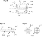
- Figure 6 shows a shaft 209 according to an embodiment, which is part of the plunger 4.
- the shaft 209 extends elongated along the longitudinal axis 205. In the operational state, the shaft 209 forms the first end 201 of the plunger 4.
- the shaft 209 is designed in particular to be coupled to the drive of the valve 100.
- the shaft 209 can be connected to the sleeve 208.
- the shaft 209 has a connecting element 210.
- the connecting element 210 is connected to a shaft body 225 in particular by means of a welded connection 222.
- Figure 7 shows views of the connecting element 210 according to an embodiment.
- the connecting element 210 has inclined projections 226.
- the projections are inclined and, for example, elastic, that they allow insertion along the longitudinal axis 205 against the opening direction 220 into the sleeve 208. Movement of the connecting element 210 relative to the sleeve 208 in the opening direction 220 is subsequently prevented by hooking the projections 226 behind in the material of the sleeve 208.
- the projections 226 penetrate slightly into the material of the sleeve 208, for example, and thus fix the connecting element 210 and thus the shaft 209 axially relative to the sleeve 208.
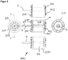
- FIG 8 shows further views of the valve 100.
- the tappet 4 which is formed from the individual parts of the shaft 209 and the sleeve 208, is held axially and radially relative to the housing body 200 by means of the spring elements 203 and 219. This reduces the number of parts of the valve 100 compared to conventional valves. An extra bearing for the second end 202 of the plunger 4 can be dispensed with. The length of the plunger 4 can thus also be reduced. This leads to lower tolerances, especially in the radial direction.
- the closing bodies 10, 218 are, for example, pressed onto the sleeve 208 and welded.
- the annular spring elements 203, 219 are welded to the closing bodies 10, 218.
- the spring elements 203, 219 are welded to the outer side 207 of the housing body 2.
- the shaft 209 is pressed into the sleeve 208 with the connecting element 210 and a self-locking mechanism is formed.
- the connecting element 210 is pressed onto the shaft body 225 and held by means of the welded connection 222.
- the illustrated double linear valve which can also be referred to as a valve module, can then be coupled to the drive.
- the closing bodies 10, 218 are floatingly mounted by means of the respective spring elements 203, 219, so that centering is always possible. In addition, the closing bodies 10, 218 are pretensioned against the opening direction 220.
- the spring elements 203, 219 make it possible to dispense with a return spring in the drive. An additional holder for the plunger 4 at the second end 202 can be dispensed with.
- the valve 100 enables a simple, compact, reliable and inexpensive construction of a valve for opening and closing exhaust lines.
Landscapes
- Engineering & Computer Science (AREA)
- General Engineering & Computer Science (AREA)
- Mechanical Engineering (AREA)
- Chemical & Material Sciences (AREA)
- Combustion & Propulsion (AREA)
- Lift Valve (AREA)
Description
- Es wird ein Ventil zum Öffnen und Schließen einer Abgasleitung angegeben.
- In Kraftfahrzeugen werden Ventile zum Öffnen und Schließen einer Abgasleitung eingesetzt. Wichtig für die Funktion solcher Ventile ist die Dichtheit, mit der das Ventil die Leitung verschließen kann. Gerade bei Gasen ist das Erreichen einer geringen Leckrate mit hohem Aufwand verbunden. Der Antrieb eines Stößels des Ventils wird typischerweise von einem Elektromotor und einem Getriebe gebildet. Das Getriebe dient dazu, die Drehbewegung des Elektromotors in eine translatorische Bewegung umzuwandeln, damit der mit dem Getriebe verbundene Stößel linear bewegt werden kann. Der Stößel ist hierzu axial geführt.
-
US 2003/0098074 A1 betrifft ein Ventil mit einer Ventilkammer, die zwischen einem Fluideinlass und einem Fluidauslass ausgebildet ist, und einem in der Ventilkammer angeordneten Ventilelement aus einem elastischen Element und einem unelastischen Element. -
GB 1 027 773 -
DE 10 2015 122 379 A1 betrifft ein Ventil, bei dem in einer ersten Stellung einer Ventilstange die Durchgangsöffnungen durch das Anliegen der festen Ventilschließglieder an den festen Ventilsitzen geschlossen sind, in einem ersten definierten Bewegungsabschnitt der Ventilstange die Durchgangsöffnung durch das flexible Element geschlossen ist und die festen Ventilschließglieder von den festen Ventilsitzen abgehoben sind und in einem an den ersten Bewegungsabschnitt anschließenden zweiten Bewegungsabschnitt der Ventilstange die Durchgangsöffnungen regelbar sind. -
DE 195 39 921 C1 betrifft ein Ventil mit einem Gehäuse, einem Einlass, einem Auslass, zwei Ventilsitzen und zwei Ventiltellern. - Es ist wünschenswert, ein Ventil anzugeben, das einfach und zuverlässig ist.
- Die Erfindung bezieht sich auf ein Ventil mit den Merkmalen des Anspruchs 1.
- Das Ventil zum Öffnen und Schließen einer Abgasleitung eines Kraftfahrzeugs weist einen Gehäusekörper auf. Das Ventil weist einen in dem Gehäusekörper angeordneten Stößel auf. Der Stößel ist an einem ersten Ende mit einem Antrieb koppelbar. Der Stößel ist ausgebildet, entlang einer Längsachse des Stößels bewegt zu werden. Das Ventil weist einen im Gehäusekörper angeordneten Ventilsitz auf. Der Ventilsitz begrenzt eine Öffnung. Das Ventil weist einen Schließkörper auf, der mit dem Stößel verbunden ist. Der Schließkörper ist mittels einer Bewegung des Stößels zwischen einer Offenstellung und einer Schließstellung verstellbar. In der Offenstellung ist die Öffnung freigegeben. In der Schließstellung liegt der Schließkörper an dem Ventilsitz an und dichtet die Öffnung ab. Das Ventil weist ein Federelement auf. Das Federelement ist an dem Gehäusekörper fixiert. Das Federelement ist zudem an dem Schließkörper fixiert. Das Federelement ist ausgebildet, eine axiale Federkraft und eine radiale Federkraft auf den Schließkörper auszuwirken.
- Das Federelement ist mit dem Gehäusekörper und dem Schließkörper verbunden, um den Schließkörper in Richtung der Schließposition vorzuspannen. Das Federelement zieht oder drückt den Schließkörper in Richtung hin zum Dichtsitz. Das Federelement ist elastisch genug, um ein Abheben des Schließkörpers vom Dichtsitz zum Öffnen des Ventils zu ermöglichen.
- Beispielsweise wird der Schließkörper mittels des Antriebs und einer Stößelbewegung in die Offenstellung bewegt.
- Zusätzlich wirkt das Federelement auch Kräfte in radialer Richtung aus. Das Federelement zieht oder drückt den Schließkörper in radialer Richtung. Insbesondere ist das Federelement ausgebildet, in mehreren Richtungen radiale Kräfte auszuwirken. Somit wird der Schließkörper beispielsweise zentriert. Der Schließkörper ist mittels des Federelements flexibel am Gehäusekörper abgestützt. Die Bewegung des Schließkörpers im Betrieb wird von dem Federelement axial und radial geführt. Dadurch wird auch die Bewegung des Stößels von dem Federelement radial und axial geführt. Somit ist es möglich, auf eine separate Lagerung des Stößels an einem dem ersten Ende abgewandten zweiten Ende zu verzichten. Im Vergleich zu herkömmlichen Ventilen für Abgasleitungen ist es dadurch möglich, die Anzahl der Bauteile zu reduzieren. Dadurch wird auch die Herstellung vereinfacht und dadurch günstiger. Zudem kann insgesamt ein kürzerer Stößel verwendet werden, was wiederum zu einem kompakteren und damit weniger fehleranfälligen Ventil führt.
- Das Federelement ist an einer Außenseite des Gehäusekörpers fixiert. Somit ist eine einfache Herstellung möglich.
- Gemäß einer Ausführungsform weist der Stößel eine Hülse auf. Der Schließkörper ist mit der Hülse verbunden. Der Stößel weist einen Schaft auf, der mit dem Antrieb koppelbar ist. Der Schaft ist teilweise in der Hülse angeordnet. Somit ist der Stößel aus zwei Einzelteilen zusammengesetzt, der Hülse und dem Schaft. Dies ermöglicht eine einfache Montage. Zunächst ist es möglich, den Schließkörper, das Federelement und den Gehäusekörper mit der Hülse zu montieren. Nachträglich kann diese Unterbaueinheit mit dem Schaft verbunden werden.
- Gemäß zumindest einer Ausführungsform weist der Schaft ein Verbindungselement auf. Das Verbindungselement ermöglicht ein Einschieben des Schafts in die Hülse zur Montage. Das Verbindungselement hinterhakt die Hülse, um den Schaft mit der Hülse zu verbinden. Das Verbindungselement ist so ausgebildet, dass nach der Montage eine Selbsthemmung auftritt. Das Verbindungselement blockiert eine relative Bewegung entlang der Längsachse zwischen dem Schaft und der Hülse nach der Montage. Das Verbindungselement ist beispielsweise flexibel genug, um ein Einstecken des Schafts in eine erste Richtung in die Hülse zu ermöglichen. Ein Herausziehen des Schafts in eine der ersten Richtung entgegengesetzte zweite Richtung wird durch ein Verhaken und ein teilweises Eindringen des Verbindungselements in die Hülse verhindert.
- Gemäß einer Ausführungsform ist das Federelement als Tellerfeder ausgebildet. Insbesondere ist das Federelement achsensymmetrisch oder punktsymmetrisch ausgebildet. Das Federelement ist insbesondere ausgebildet, dass in jede radiale Richtung in etwa die gleiche Kraft ausgewirkt wird.
- Gemäß einer Ausführungsform weist das Federelement einen ersten Ring und einen zweiten Ring auf. Der erste Ring ist an dem Gehäusekörper fixiert und der zweite Ring ist an dem Schließkörper fixiert. Dadurch ist eine verlässliche und einfache Verbindung zwischen dem Federelement und dem Gehäusekörper sowie dem Schließkörper möglich.
- Gemäß einer Ausführungsform ist das Federelement an dem Gehäusekörper und an dem Schließkörper jeweils mittels einer Schweißverbindung fixiert. Dies ermöglicht eine einfache und zuverlässige Verbindung.
- Gemäß einer Ausführungsform endet der Stößel in der Schließposition an einem dem ersten Ende gegenüberliegenden zweiten Ende in der Öffnung. Der Stößel steht insbesondere an dem zweiten Ende nicht über den Gehäusekörper über. Somit ist im Vergleich zu herkömmlichen Ventilen ein verkürzter Stößel möglich. Die Führung des Stößels mittels des Federelements und des Schließkörpers ermöglicht, dass der Stößel an dem zweiten Ende nicht in einem separaten Lager geführt ist, das außerhalb des Gehäusekörpers angeordnet ist.
- Gemäß einer Ausführungsform ist der Schließkörper an dem zweiten Ende mit dem Stößel verbunden. Der Stößel steht nicht oder nur unwesentlich über den Schließkörper vor in eine Richtung weg vom Antrieb.
- Das Ventil weist einen im Gehäusekörper angeordneten zweiten Ventilsitz auf. Der zweite Ventilsitz begrenzt eine zweite Öffnung. Das Ventil weist einen zweiten Schließkörper auf. Der zweite Schließkörper ist zwischen dem ersten Ende und dem zweiten Ende mit dem Stößel verbunden. Der zweite Schließkörper ist mittels einer Bewegung des Stößels zwischen der Offenstellung und der Schließstellung verstellbar. In der Offenstellung gibt der Schließkörper die zweite Öffnung frei. In der Schließstellung dichtet der zweite Schließkörper die zweite Öffnung ab, indem er an dem zweiten Ventilsitz anliegt. Das Ventil weist ein zweites Federelement auf, das an dem Gehäusekörper fixiert ist. Das zweite Federelement ist an dem zweiten Schließkörper fixiert, um eine axiale Federkraft und eine radiale Federkraft auf den zweiten Schließkörper auszuwirken. Das zweite Federelement ist korrespondierend zum ersten Federelement ausgebildet, sodass die im Zusammenhang mit dem ersten Federelement beschriebenen Merkmale und Vorteile auch für das zweite Federelement gelten.
- Das beschriebene Ventil eignet sich insbesondere für Linearventile, bei denen der Stößel entlang einer Richtung, insbesondere seiner Längsachse linear bewegt wird. Das Ventil kann als Doppellinearventil ausgebildet sein oder mit nur einem einzigen Schließkörper als Einfachlinearventil. Beim Doppellinearventil wird die zweite Öffnung gleichzeitig zur ersten Öffnung durch die Stößelbewegung verschlossen oder freigegeben.
- Beispielsweise ist das Ventil in einem Abgasrückführsystem eines Kraftfahrzeugs einsetzbar, um die Abgasleitung des Kraftfahrzeugs zu öffnen und zu schließen. Beispielsweise weist ein Abgasrückführsystem eines Kraftfahrzeugs das Ventil auf.
- Weitere Vorteile, Merkmale und Weiterbildungen ergeben sich aus den nachfolgenden, in Verbindung mit den Figuren erläuterten Ausführungsbeispielen. Gleiche, gleichartige oder gleich wirkende Elemente können figurenübergreifend mit den gleichen Bezugszeichen versehen sein.
- Es zeigen:
- Figur 1
- eine schematische Schnittansicht eines bekannten Ventils, welches zumindest nicht die Merkmale des kennzeichnenden Teils von Anspruch zeigt,
- Figur 2
- eine schematische Schnittansicht eines Ventils gemäß einem Ausführungsbeispiel der Erfindung,
- Figur 3
- eine schematische Darstellung eines Teils des Ventils gemäß
Figur 2 , - Figur 4
- eine schematische Darstellung eines Federelements gemäß
Figur 2 , - Figur 5
- eine schematische Darstellung eines Teils des Ventils gemäß
Figur 2 , - Figur 6
- eine schematische Darstellung eines Schafts des Ventils gemäß
Figur 2 , - Figur 7
- schematische Darstellungen eines Verbindungselements des Ventils gemäß
Figur 2 , und - Figur 8
- verschiedene Ansichten des Ventils gemäß
Figur 2 . -
Figur 1 zeigt ein Ventil 100 zum Öffnen und Schließen einer Abgasleitung, welches zumindest nicht die Merkmale des kennzeichnenden Teils von Anspruch 1 zeigt. Das Ventil 100 inFigur 1 weist ein Gehäuse 1 auf, in dem ein Elektromotor 2 angeordnet ist. Mittels eines Getriebes 3 wird die Drehbewegung des Elektromotors 2 in eine lineare Bewegung eines Stößels 4 umgewandelt. Am Getriebe 3 ist ein Sensor 5 angeordnet, der mit einem am Stößel 4 befestigten Magneten zusammenwirkt. Der Stößel 4 erstreckt sich von der Getriebekammer 6 bis in eine Ventilkammer 7, wobei der Stößel 4 an zwei Stellen 8 gelagert ist. Die Ventilkammer 7 besteht aus drei hintereinander liegenden Teilkammern 7a, 7b, 7c, die jeweils durch einen Ventilsitz 9 voneinander getrennt sind. Zwei Schließkörper 10 sind so auf dem Stößel 4 angeordnet, dass sie sich bei einer Bewegung des Stößels 4 entlang einer Längsachse 205 des Stößels 4 an den jeweiligen Ventilsitz 9 anlegen und eine Öffnung 11 abdichten oder vom Ventilsitz 9 wegbewegen und die Öffnung 11 somit freigeben, dass ein Gas von einer Ventilkammer 7 in die andere strömen kann. - Im Folgenden wird ein Ventil 100 gemäß einem Ausführungsbeispiel der Erfindung beschrieben, das eine veränderte Lagerung und Führung für den Stößel 4, gemäß der Ansprüche 1-8, aufweist. Im Übrigen kann das Ventil 100 die Merkmale der anhand von
Figur 1 beschriebenen Ausgestaltung aufweisen. -
Figur 2 zeigt eine Schnittansicht eines Teils des Ventils 100. Der Stößel 4 erstreckt sich entlang der Längsachse 205 von einem ersten Ende 201 zu einem zweiten Ende 202. Am ersten Ende 201 ist der Stößel 4 mit dem Antrieb koppelbar, also beispielsweise mit dem Getriebe 3. An dem zweiten Ende 202 ist der Schließkörper 10 angeordnet. Zwischen dem ersten Ende 201 und dem zweiten Ende 202 ist ein zweiter Schließkörper 218 angeordnet und an dem Stößel 4 fixiert. Beispielsweise weist der Schließkörper 10 einen ersten Durchmesser 223 auf. Der zweite Schließkörper 218 weist einen zweiten Durchmesser 224 auf. Der zweite Durchmesser 224 ist insbesondere größer als der erste Durchmesser 223. Somit sind die beiden Schließkörper 10, 218 unterschiedlich groß. - Der Schließkörper 10 ist dem Ventilsitz 9 zugeordnet, der in einem Gehäusekörper 200 ausgebildet ist. Der Gehäusekörper 200 umgibt insbesondere die Teilkammer 7b. Auf die Teilkammer 7c (
Figur 1 ) kann in dem erfindungsgemäßen Ventil 100 verzichtet werden. Der Ventilsitz 9 umgibt die Öffnung 11. Der Gehäusekörper 200 weist einen zweiten Ventilsitz 216 auf. Der zweite Schließkörper 218 ist im zweiten Ventilsitz 216 zugeordnet. Der zweite Ventilsitz 216 umgibt eine zweite Öffnung 217. Zum Öffnen des Ventils werden die Schließkörper 10, 218 von den jeweiligen Ventilsitzen 9, 216 in eine Öffnungsrichtung 220 bewegt. - Der Gehäusekörper 200 ist beispielsweise in dem Gehäuse 1 angeordnet und an dem Gehäuse 1 befestigt. Alternativ ersetzt der Gehäusekörper 200 beispielsweise das Gehäuse 1. Der Antrieb ist beispielsweise an dem Gehäusekörper 200 befestigt.
- Den Schließkörpern 10, 218 ist ein jeweiliges Federelement 203, 219 zugeordnet, das eine Kraft auf den jeweils zugeordneten Schließkörper 10, 218 entgegen der Öffnungsrichtung 220 auswirkt. Die Federelemente 203, 219 sind somit ausgebildet, eine axiale Federkraft 204 auf die Schließkörper 10, 218 auszuwirken, um das Ventil in der Schließstellung zu halten.
- Das Federelement 203 ist an dem Gehäusekörper 200 fixiert, beispielsweise mittels einer Schweißverbindung 214 (
Figur 5 ). Das Federelement 203 ist zudem an dem Schließkörper 10 fixiert, beispielsweise mittels einer Schweißverbindung 215 (Figur 5 ). Korrespondierend ist das zweite Federelement 219 mittels einer Schweißverbindung 214 mit dem Gehäusekörper 200 verbunden. Das zweite Federelement 219 ist mittels einer Schweißverbindung 215 mit dem zweiten Schließkörper 218 verbunden (Figur 5 ). Somit ist es möglich, dass die Federelemente 203, 219 Zug- und Druckkräfte zwischen dem Gehäusekörper 200 und den Schließkörpern 10, 218 auswirken. - Zusätzlich zu der axialen Federkraft 204 sind die Federelemente 203, 219 jeweils dazu ausgebildet, eine radiale Federkraft 206 auszuwirken. Somit sind die Schließkörper 10, 218 mittels des jeweiligen Federelements 203, 219 auch radial geführt. Die Schließkörper 10, 218 sind wiederum mit dem Stößel 4 verbunden. Somit ist auch der Stößel 4 mittels der Federelemente 203, 219 relativ zum Gehäusekörper 200 radial geführt. Auf eine zusätzliche Lagerung insbesondere am zweiten Ende 202 kann dadurch verzichtet werden.
- Zur Montage des Ventils 100 wird zunächst der Gehäusekörper 200 bereitgestellt. Der Schließkörper 10 wird mittels einer Schweißverbindung 221 an einer Hülse 208 des Stößels 4 befestigt, wie insbesondere in
Figur 3 dargestellt ist. Der zweite Schließkörper 218 wird mittels einer Schweißverbindung 221 an der Hülse 208 befestigt. Die Hülse 208 wird mit den Schließkörpern 10, 218 am Gehäusekörper 200 angeordnet. Aufgrund des geringeren Durchmessers 223 des Schließkörpers 10 ist dieser durch die zweite Öffnung 217 hindurch in die Teilkammer 7b einbringbar, die von dem Gehäusekörper 200 umgeben ist. -
Figur 4 zeigt eine exemplarische Darstellung der Federelemente 203, 219. Die Federelemente 203, 219 weisen jeweils einen ersten Ring 211 auf. Die Federelemente 203, 219 weisen jeweils einen zweiten Ring 212 auf. Der erste Ring 211 hat einen größeren Durchmesser als der zweite Ring 212. Die beiden Ringe 211, 212 sind koaxial angeordnet. Die beiden Ringe 211, 212 sind mittels Federverbindungen 213 miteinander verbunden. Die Federverbindungen 213 ermöglichen eine Relativbewegung der beiden Ringe 211, 212 relativ zueinander. Zudem ermöglichen die Federverbindungen 213 das Auswirken der axialen Federkraft 204 sowie der radialen Federkraft 206. Der erste Ring 211 ist dazu ausgebildet, mit dem Gehäusekörper 200 verbunden zu werden. Der zweite Ring 212 ist dazu ausgebildet, mit einem der Schließkörper 10, 218 verbunden zu werden. -
Figur 5 zeigt die Anordnung derFigur 3 mit zusätzlich montierten Federelementen 203, 219. Die Federelemente 203 sind jeweils an einer Außenseite 207 des Gehäusekörpers 200 mit den jeweiligen ersten Ringen 211 und den Schweißverbindungen 214 verbunden. Die zweiten Ringe 212 sind jeweils mittels der Schweißverbindung 215 mit den jeweiligen zugeordneten Schließkörpern 10, 218 verbunden. -
Figur 6 zeigt einen Schaft 209 gemäß einem Ausführungsbeispiel, der Teil des Stößels 4 ist. Der Schaft 209 erstreckt sich länglich ausgedehnt entlang der Längsachse 205. Im betriebsfertigen Zustand bildet der Schaft 209 das erste Ende 201 des Stößels 4 aus. Der Schaft 209 ist insbesondere dazu ausgebildet, mit dem Antrieb des Ventils 100 gekoppelt zu werden. Zudem ist der Schaft 209 mit der Hülse 208 verbindbar. Zum Verbinden mit der Hülse 208 weist der Schaft 209 ein Verbindungselement 210 auf. Das Verbindungselement 210 ist insbesondere mittels einer Schweißverbindung 222 mit einem Schaftkörper 225 verbunden. -
Figur 7 zeigt Ansichten des Verbindungselements 210 gemäß einem Ausführungsbeispiel. Das Verbindungselement 210 weist geneigte Vorsprünge 226 auf. Die Vorsprünge sind so geneigt und beispielsweise elastisch ausgebildet, dass sie ein Einschieben entlang der Längsachse 205 entgegen der Öffnungsrichtung 220 in die Hülse 208 ermöglichen. Eine Bewegung des Verbindungselements 210 relativ zu der Hülse 208 in die Öffnungsrichtung 220 wird nachfolgend durch ein Hinterhaken der Vorsprünge 226 in dem Material der Hülse 208 verhindert. Die Vorsprünge 226 dringen beispielsweise leicht in das Material der Hülse 208 ein und fixieren so das Verbindungselement 210 und damit den Schaft 209 axial relativ zu der Hülse 208. -
Figur 8 zeigt weitere Ansichten des Ventils 100. Der Stößel 4, der aus den Einzelteilen Schaft 209 und Hülse 208 ausgebildet ist, ist mittels der Federelemente 203 und 219 axial und radial relativ zum Gehäusekörper 200 gehalten. Dadurch ist die Anzahl der Teile des Ventils 100 im Vergleich zu herkömmlichen Ventilen reduziert. Auf eine Extralagerung für das zweite Ende 202 des Stößels 4 kann verzichtet werden. Somit ist auch die Länge des Stößels 4 verringerbar. Dies führt zu geringeren Toleranzen, insbesondere in radialer Richtung. - Die Schließkörper 10, 218 sind beispielsweise auf die Hülse 208 aufgepresst und verschweißt. Die ringförmigen Federelemente 203, 219 sind mit den Schließkörpern 10, 218 verschweißt. Zudem sind die Federelemente 203, 219 mit der Au-βenseite 207 des Gehäusekörpers 2 verschweißt. Der Schaft 209 ist mit dem Verbindungselement 210 in die Hülse 208 eingepresst und eine Selbstverriegelung ausgebildet. Das Verbindungselement 210 ist auf den Schaftkörper 225 aufgepresst und mittels der Schweißverbindung 222 gehalten. Das dargestellte Doppellinearventil, das auch als Ventilmodul bezeichnet werden kann, ist dann mit dem Antrieb koppelbar.
- Die Schließkörper 10, 218 sind mittels der jeweiligen Federelemente 203, 219 schwimmend gelagert, sodass stets eine Zentrierung ermöglicht ist. Zudem sind die Schließkörper 10, 218 entgegen der Öffnungsrichtung 220 vorgespannt. Die Federelemente 203, 219 ermöglichen, auf eine Rückstellfeder im Antrieb zu verzichten. Auf eine zusätzliche Halterung für den Stößel 4 am zweiten Ende 202 kann verzichtet werden.
- Das Ventil 100 ermöglicht einen einfachen, kompakten, zuverlässigen und kostengünstigen Aufbau eines Ventils zum Öffnen und Schließen von Abgasleitungen.
Claims (8)
- Ventil zum Öffnen und Schließen einer Abgasleitung, aufweisend:- ein Gehäusekörper (200),- einen in dem Gehäusekörper (200) angeordneten Stößel (4), der an einem ersten Ende (201) mit einem Antrieb koppelbar ist und ausgebildet ist, entlang einer Längsachse (205) des Stößels (4) bewegt zu werden,- einen im Gehäusekörper (200) angeordneten Ventilsitz (9) der eine Öffnung (11) begrenzt, und- einen Schließkörper (10), der mit dem Stößel (4) verbunden ist, so dass der Schließkörper (10) mittels einer Bewegung des Stößels (4) zwischen einer Offenstellung, in der die Öffnung (11) freigegeben ist, und einer Schließstellung verstellbar ist, in der der Schließkörper (10) an dem Ventilsitz (9) anliegt und die Öffnung (11) abdichtet,- ein Federelement (203), das an dem Gehäusekörper (200) fixiert ist und das an dem Schließkörper (10) fixiert ist, um eine axiale Federkraft (204) und eine radiale Federkraft (206) auf den Schließkörper (10) auszuwirken,- einen im Gehäusekörper (200) angeordneten zweiten Ventilsitz (216), der eine zweite Öffnung (217) begrenzt, und- einen zweiten Schließkörper (218), der zwischen dem ersten Ende (201) und dem zweiten Ende (202) mit dem Stößel (4) verbunden ist, so dass der zweite Schließkörper (218) mittels einer Bewegung des Stößels (4) zwischen der Offenstellung, in der die zweite Öffnung (217) freigegeben ist, und der Schließstellung verstellbar ist, in der der zweite Schließkörper (218) an dem zweiten Ventilsitz (216) anliegt und die zweite Öffnung (217) abdichtet, dadurch gekennzeichnet, dass- ein zweites Federelement (219), an dem Gehäusekörper (200) fixiert ist und an dem zweiten Schließkörper (218) fixiert ist, um eine axiale Federkraft (204) und eine radiale Federkraft (206) auf den zweiten Schließkörper (218) auszuwirken und,
dass das Federelement (203) und das zweites Federelement (219) jeweils an einer Außenseite (207) des Gehäusekörpers (200) fixiert sind. - Ventil nach Anspruch 1, bei dem der Stößel (4) eine Hülse (208) aufweist, mit der der Schließkörper (1 0) verbunden ist, und bei der der Stößel (4) einen Schaft (209) aufweist, der mit dem Antrieb koppelbar ist und der teilweise in der Hülse (208) angeordnet ist.
- Ventil nach Anspruch 2, bei dem der Schaft (209) ein Verbindungselement (210) aufweist, das ein Einschieben des Schafts (209) in die Hülse (208) zur Montage ermöglicht und das die Hülse (208) hinterhakt, um den Schaft (209) mit der Hülse (208) zu verbinden.
- Ventil nach einem der Ansprüche 1 bis 3, beim dem die Federelemente (203, 219) als Tellerfedern ausgebildet sind.
- Ventil nach einem der Ansprüche 1 bis 4, bei dem die Federelemente (203, 219) jeweils einen ersten Ring (211) und einen zweiten Ring (212) aufweisen, wobei jeweils der erste Ring (211) an dem Gehäusekörper (200) fixiert ist und der zweite Ring (212) an einem der Schließkörper (10, 218) fixiert ist.
- Ventil nach einem der Ansprüche 1 bis 5, bei die Federelemente (203, 219) an dem Gehäusekörper (200) und an einem der Schließkörper (10, 218) jeweils mittels einer Schweißverbindung (214, 215) fixiert sind
- Ventil nach einem der Ansprüche 1 bis 6, bei dem der Stößel (4) in der Schließposition an einem dem ersten Ende (201) gegenüberliegenden zweiten Ende (202) in der Öffnung (11) endet.
- Ventil nach einem der Ansprüche 1 bis 7, bei dem der Schließkörper (10) an dem zweiten Ende (202) mit dem Stößel (4) verbunden ist.
Priority Applications (1)
| Application Number | Priority Date | Filing Date | Title |
|---|---|---|---|
| EP18465580.1A EP3628853B1 (de) | 2018-09-28 | 2018-09-28 | Ventil |
Applications Claiming Priority (1)
| Application Number | Priority Date | Filing Date | Title |
|---|---|---|---|
| EP18465580.1A EP3628853B1 (de) | 2018-09-28 | 2018-09-28 | Ventil |
Publications (2)
| Publication Number | Publication Date |
|---|---|
| EP3628853A1 EP3628853A1 (de) | 2020-04-01 |
| EP3628853B1 true EP3628853B1 (de) | 2021-12-29 |
Family
ID=63965593
Family Applications (1)
| Application Number | Title | Priority Date | Filing Date |
|---|---|---|---|
| EP18465580.1A Active EP3628853B1 (de) | 2018-09-28 | 2018-09-28 | Ventil |
Country Status (1)
| Country | Link |
|---|---|
| EP (1) | EP3628853B1 (de) |
Cited By (1)
| Publication number | Priority date | Publication date | Assignee | Title |
|---|---|---|---|---|
| EP3864326B1 (de) * | 2018-10-11 | 2024-08-21 | Vitesco Technologies GmbH | Ventil |
Families Citing this family (1)
| Publication number | Priority date | Publication date | Assignee | Title |
|---|---|---|---|---|
| FR3122225A1 (fr) * | 2021-04-21 | 2022-10-28 | Bontaz Centre R & D | Dispositif de liaison par clipsage presentant une tenue a la traction amelioree |
Family Cites Families (10)
| Publication number | Priority date | Publication date | Assignee | Title |
|---|---|---|---|---|
| GB1027773A (en) * | 1962-11-27 | 1966-04-27 | Westinghouse Brake & Signal | Guides |
| DE1675575A1 (de) * | 1967-07-29 | 1970-12-23 | Samson Appbau Ag | Ventilkegelbefestigung |
| DE19539921C1 (de) * | 1995-10-26 | 1997-02-27 | Ranco Inc | Ventil |
| JPH11324823A (ja) * | 1998-05-19 | 1999-11-26 | Nippon Soken Inc | 排気ガス再循環装置 |
| ATE352737T1 (de) * | 2000-04-03 | 2007-02-15 | Siemens Schweiz Ag | Absperrventil |
| JP3846287B2 (ja) * | 2001-11-27 | 2006-11-15 | 三浦工業株式会社 | バルブ |
| CN101960133B (zh) * | 2008-04-08 | 2013-04-17 | 三菱电机株式会社 | 排气气体再循环气门和排气气体再循环气门的制造方法 |
| DE102008037019B4 (de) * | 2008-08-08 | 2017-12-14 | Continental Automotive Gmbh | Leitungsanordnung für ein Fluid und Verfahren zum Koppeln von Leitungselementen |
| JP2012026270A (ja) * | 2008-11-25 | 2012-02-09 | Mitsubishi Electric Corp | Egrバルブ装置および弁軸組み付け方法 |
| DE102015122379B4 (de) * | 2015-12-21 | 2018-10-11 | Pierburg Gmbh | Ventilvorrichtung für eine Verbrennungskraftmaschine |
-
2018
- 2018-09-28 EP EP18465580.1A patent/EP3628853B1/de active Active
Cited By (1)
| Publication number | Priority date | Publication date | Assignee | Title |
|---|---|---|---|---|
| EP3864326B1 (de) * | 2018-10-11 | 2024-08-21 | Vitesco Technologies GmbH | Ventil |
Also Published As
| Publication number | Publication date |
|---|---|
| EP3628853A1 (de) | 2020-04-01 |
Similar Documents
| Publication | Publication Date | Title |
|---|---|---|
| EP2411645B1 (de) | Klappenanordnung, insbesondere abgasklappenanordnung | |
| DE102010035622B4 (de) | Abgasrückführventil für eine Verbrennungskraftmaschine | |
| EP1210165B1 (de) | Filter mit ventil-kombinationsbauteil | |
| DE102016105840A1 (de) | Membranventil | |
| EP3628853B1 (de) | Ventil | |
| EP3280904A1 (de) | Gasventil | |
| DE102009056251B4 (de) | Ventilvorrichtung für eine Verbrennungskraftmaschine | |
| DE102007003213A1 (de) | Gas-Einblasventil | |
| DE102019120225A1 (de) | Ventil und Vorrichtung zur Regelung von Drücken eines Strömungsmittels mit dem Ventil sowie Vorrichtung zur Sicherung des Ventils in dem Getriebebauteil | |
| DE102011050263B4 (de) | Ventilvorrichtung für eine Verbrennungskraftmaschine | |
| DE102007004870A1 (de) | Ventil zum Steuern von Fluiden, insbesondere Brennstoffeinspritzventil | |
| DE102016103549B3 (de) | Ventilvorrichtung für eine Verbrennungskraftmaschine | |
| EP3628852B1 (de) | Ventil und verfahren zum herstellen eines ventils | |
| EP3626950B1 (de) | Ventil sowie verfahren zum herstellen eines ventils | |
| EP3626949B1 (de) | Ventil | |
| DE102008027242B4 (de) | Verfahren zum Montieren einer Klappe in einem Gehäuse | |
| EP2772625A2 (de) | Antriebsanordnung für ein Aggregat eines Verbrennungsmotors | |
| DE102014102524A1 (de) | Anordnung zur Befestigung eines Regelventils an einem Strömungskanalgehäuse eines Verbrennungsmotors | |
| DE10029297A1 (de) | Ventil zum Steuern von Flüssigkeiten | |
| EP3626948B1 (de) | Ventil sowie verfahren zum herstellen eines ventils | |
| EP3620636B1 (de) | Druckluftentnahmeventil | |
| DE102019120221A1 (de) | Ventil zur Regelung von Drücken eines Strömungsmittels | |
| DE102012110763A1 (de) | Klappenvorrichtung für eine Verbrennungskraftmaschine oder ein Elektrofahrzeug | |
| DE102023125160A1 (de) | Ventil | |
| EP4310375A1 (de) | Ventileinheit und verfahren zur herstellung der ventileinheit |
Legal Events
| Date | Code | Title | Description |
|---|---|---|---|
| PUAI | Public reference made under article 153(3) epc to a published international application that has entered the european phase |
Free format text: ORIGINAL CODE: 0009012 |
|
| STAA | Information on the status of an ep patent application or granted ep patent |
Free format text: STATUS: THE APPLICATION HAS BEEN PUBLISHED |
|
| AK | Designated contracting states |
Kind code of ref document: A1 Designated state(s): AL AT BE BG CH CY CZ DE DK EE ES FI FR GB GR HR HU IE IS IT LI LT LU LV MC MK MT NL NO PL PT RO RS SE SI SK SM TR |
|
| AX | Request for extension of the european patent |
Extension state: BA ME |
|
| RAP1 | Party data changed (applicant data changed or rights of an application transferred) |
Owner name: VITESCO TECHNOLOGIES GMBH |
|
| STAA | Information on the status of an ep patent application or granted ep patent |
Free format text: STATUS: REQUEST FOR EXAMINATION WAS MADE |
|
| 17P | Request for examination filed |
Effective date: 20201001 |
|
| RBV | Designated contracting states (corrected) |
Designated state(s): AL AT BE BG CH CY CZ DE DK EE ES FI FR GB GR HR HU IE IS IT LI LT LU LV MC MK MT NL NO PL PT RO RS SE SI SK SM TR |
|
| STAA | Information on the status of an ep patent application or granted ep patent |
Free format text: STATUS: EXAMINATION IS IN PROGRESS |
|
| 17Q | First examination report despatched |
Effective date: 20210208 |
|
| GRAP | Despatch of communication of intention to grant a patent |
Free format text: ORIGINAL CODE: EPIDOSNIGR1 |
|
| STAA | Information on the status of an ep patent application or granted ep patent |
Free format text: STATUS: GRANT OF PATENT IS INTENDED |
|
| INTG | Intention to grant announced |
Effective date: 20210811 |
|
| GRAS | Grant fee paid |
Free format text: ORIGINAL CODE: EPIDOSNIGR3 |
|
| GRAA | (expected) grant |
Free format text: ORIGINAL CODE: 0009210 |
|
| STAA | Information on the status of an ep patent application or granted ep patent |
Free format text: STATUS: THE PATENT HAS BEEN GRANTED |
|
| RAP3 | Party data changed (applicant data changed or rights of an application transferred) |
Owner name: VITESCO TECHNOLOGIES GMBH |
|
| AK | Designated contracting states |
Kind code of ref document: B1 Designated state(s): AL AT BE BG CH CY CZ DE DK EE ES FI FR GB GR HR HU IE IS IT LI LT LU LV MC MK MT NL NO PL PT RO RS SE SI SK SM TR |
|
| REG | Reference to a national code |
Ref country code: GB Ref legal event code: FG4D Free format text: NOT ENGLISH |
|
| REG | Reference to a national code |
Ref country code: CH Ref legal event code: EP |
|
| REG | Reference to a national code |
Ref country code: AT Ref legal event code: REF Ref document number: 1458854 Country of ref document: AT Kind code of ref document: T Effective date: 20220115 |
|
| REG | Reference to a national code |
Ref country code: IE Ref legal event code: FG4D Free format text: LANGUAGE OF EP DOCUMENT: GERMAN |
|
| REG | Reference to a national code |
Ref country code: DE Ref legal event code: R096 Ref document number: 502018008319 Country of ref document: DE |
|
| REG | Reference to a national code |
Ref country code: LT Ref legal event code: MG9D |
|
| PG25 | Lapsed in a contracting state [announced via postgrant information from national office to epo] |
Ref country code: RS Free format text: LAPSE BECAUSE OF FAILURE TO SUBMIT A TRANSLATION OF THE DESCRIPTION OR TO PAY THE FEE WITHIN THE PRESCRIBED TIME-LIMIT Effective date: 20211229 Ref country code: LT Free format text: LAPSE BECAUSE OF FAILURE TO SUBMIT A TRANSLATION OF THE DESCRIPTION OR TO PAY THE FEE WITHIN THE PRESCRIBED TIME-LIMIT Effective date: 20211229 Ref country code: FI Free format text: LAPSE BECAUSE OF FAILURE TO SUBMIT A TRANSLATION OF THE DESCRIPTION OR TO PAY THE FEE WITHIN THE PRESCRIBED TIME-LIMIT Effective date: 20211229 Ref country code: BG Free format text: LAPSE BECAUSE OF FAILURE TO SUBMIT A TRANSLATION OF THE DESCRIPTION OR TO PAY THE FEE WITHIN THE PRESCRIBED TIME-LIMIT Effective date: 20220329 |
|
| REG | Reference to a national code |
Ref country code: NL Ref legal event code: MP Effective date: 20211229 |
|
| PG25 | Lapsed in a contracting state [announced via postgrant information from national office to epo] |
Ref country code: SE Free format text: LAPSE BECAUSE OF FAILURE TO SUBMIT A TRANSLATION OF THE DESCRIPTION OR TO PAY THE FEE WITHIN THE PRESCRIBED TIME-LIMIT Effective date: 20211229 Ref country code: NO Free format text: LAPSE BECAUSE OF FAILURE TO SUBMIT A TRANSLATION OF THE DESCRIPTION OR TO PAY THE FEE WITHIN THE PRESCRIBED TIME-LIMIT Effective date: 20220329 Ref country code: LV Free format text: LAPSE BECAUSE OF FAILURE TO SUBMIT A TRANSLATION OF THE DESCRIPTION OR TO PAY THE FEE WITHIN THE PRESCRIBED TIME-LIMIT Effective date: 20211229 Ref country code: HR Free format text: LAPSE BECAUSE OF FAILURE TO SUBMIT A TRANSLATION OF THE DESCRIPTION OR TO PAY THE FEE WITHIN THE PRESCRIBED TIME-LIMIT Effective date: 20211229 Ref country code: GR Free format text: LAPSE BECAUSE OF FAILURE TO SUBMIT A TRANSLATION OF THE DESCRIPTION OR TO PAY THE FEE WITHIN THE PRESCRIBED TIME-LIMIT Effective date: 20220330 |
|
| PG25 | Lapsed in a contracting state [announced via postgrant information from national office to epo] |
Ref country code: NL Free format text: LAPSE BECAUSE OF FAILURE TO SUBMIT A TRANSLATION OF THE DESCRIPTION OR TO PAY THE FEE WITHIN THE PRESCRIBED TIME-LIMIT Effective date: 20211229 |
|
| PG25 | Lapsed in a contracting state [announced via postgrant information from national office to epo] |
Ref country code: SM Free format text: LAPSE BECAUSE OF FAILURE TO SUBMIT A TRANSLATION OF THE DESCRIPTION OR TO PAY THE FEE WITHIN THE PRESCRIBED TIME-LIMIT Effective date: 20211229 Ref country code: SK Free format text: LAPSE BECAUSE OF FAILURE TO SUBMIT A TRANSLATION OF THE DESCRIPTION OR TO PAY THE FEE WITHIN THE PRESCRIBED TIME-LIMIT Effective date: 20211229 Ref country code: RO Free format text: LAPSE BECAUSE OF FAILURE TO SUBMIT A TRANSLATION OF THE DESCRIPTION OR TO PAY THE FEE WITHIN THE PRESCRIBED TIME-LIMIT Effective date: 20211229 Ref country code: PT Free format text: LAPSE BECAUSE OF FAILURE TO SUBMIT A TRANSLATION OF THE DESCRIPTION OR TO PAY THE FEE WITHIN THE PRESCRIBED TIME-LIMIT Effective date: 20220429 Ref country code: ES Free format text: LAPSE BECAUSE OF FAILURE TO SUBMIT A TRANSLATION OF THE DESCRIPTION OR TO PAY THE FEE WITHIN THE PRESCRIBED TIME-LIMIT Effective date: 20211229 Ref country code: EE Free format text: LAPSE BECAUSE OF FAILURE TO SUBMIT A TRANSLATION OF THE DESCRIPTION OR TO PAY THE FEE WITHIN THE PRESCRIBED TIME-LIMIT Effective date: 20211229 Ref country code: CZ Free format text: LAPSE BECAUSE OF FAILURE TO SUBMIT A TRANSLATION OF THE DESCRIPTION OR TO PAY THE FEE WITHIN THE PRESCRIBED TIME-LIMIT Effective date: 20211229 |
|
| PG25 | Lapsed in a contracting state [announced via postgrant information from national office to epo] |
Ref country code: PL Free format text: LAPSE BECAUSE OF FAILURE TO SUBMIT A TRANSLATION OF THE DESCRIPTION OR TO PAY THE FEE WITHIN THE PRESCRIBED TIME-LIMIT Effective date: 20211229 |
|
| PG25 | Lapsed in a contracting state [announced via postgrant information from national office to epo] |
Ref country code: IS Free format text: LAPSE BECAUSE OF FAILURE TO SUBMIT A TRANSLATION OF THE DESCRIPTION OR TO PAY THE FEE WITHIN THE PRESCRIBED TIME-LIMIT Effective date: 20220429 |
|
| REG | Reference to a national code |
Ref country code: DE Ref legal event code: R097 Ref document number: 502018008319 Country of ref document: DE |
|
| PG25 | Lapsed in a contracting state [announced via postgrant information from national office to epo] |
Ref country code: DK Free format text: LAPSE BECAUSE OF FAILURE TO SUBMIT A TRANSLATION OF THE DESCRIPTION OR TO PAY THE FEE WITHIN THE PRESCRIBED TIME-LIMIT Effective date: 20211229 Ref country code: AL Free format text: LAPSE BECAUSE OF FAILURE TO SUBMIT A TRANSLATION OF THE DESCRIPTION OR TO PAY THE FEE WITHIN THE PRESCRIBED TIME-LIMIT Effective date: 20211229 |
|
| PLBE | No opposition filed within time limit |
Free format text: ORIGINAL CODE: 0009261 |
|
| STAA | Information on the status of an ep patent application or granted ep patent |
Free format text: STATUS: NO OPPOSITION FILED WITHIN TIME LIMIT |
|
| 26N | No opposition filed |
Effective date: 20220930 |
|
| PG25 | Lapsed in a contracting state [announced via postgrant information from national office to epo] |
Ref country code: SI Free format text: LAPSE BECAUSE OF FAILURE TO SUBMIT A TRANSLATION OF THE DESCRIPTION OR TO PAY THE FEE WITHIN THE PRESCRIBED TIME-LIMIT Effective date: 20211229 |
|
| PG25 | Lapsed in a contracting state [announced via postgrant information from national office to epo] |
Ref country code: MC Free format text: LAPSE BECAUSE OF FAILURE TO SUBMIT A TRANSLATION OF THE DESCRIPTION OR TO PAY THE FEE WITHIN THE PRESCRIBED TIME-LIMIT Effective date: 20211229 |
|
| REG | Reference to a national code |
Ref country code: CH Ref legal event code: PL |
|
| GBPC | Gb: european patent ceased through non-payment of renewal fee |
Effective date: 20220928 |
|
| REG | Reference to a national code |
Ref country code: BE Ref legal event code: MM Effective date: 20220930 |
|
| PG25 | Lapsed in a contracting state [announced via postgrant information from national office to epo] |
Ref country code: IT Free format text: LAPSE BECAUSE OF FAILURE TO SUBMIT A TRANSLATION OF THE DESCRIPTION OR TO PAY THE FEE WITHIN THE PRESCRIBED TIME-LIMIT Effective date: 20211229 |
|
| PG25 | Lapsed in a contracting state [announced via postgrant information from national office to epo] |
Ref country code: LU Free format text: LAPSE BECAUSE OF NON-PAYMENT OF DUE FEES Effective date: 20220928 |
|
| P01 | Opt-out of the competence of the unified patent court (upc) registered |
Effective date: 20230530 |
|
| PG25 | Lapsed in a contracting state [announced via postgrant information from national office to epo] |
Ref country code: LI Free format text: LAPSE BECAUSE OF NON-PAYMENT OF DUE FEES Effective date: 20220930 Ref country code: IE Free format text: LAPSE BECAUSE OF NON-PAYMENT OF DUE FEES Effective date: 20220928 Ref country code: CH Free format text: LAPSE BECAUSE OF NON-PAYMENT OF DUE FEES Effective date: 20220930 |
|
| PG25 | Lapsed in a contracting state [announced via postgrant information from national office to epo] |
Ref country code: BE Free format text: LAPSE BECAUSE OF NON-PAYMENT OF DUE FEES Effective date: 20220930 |
|
| PG25 | Lapsed in a contracting state [announced via postgrant information from national office to epo] |
Ref country code: GB Free format text: LAPSE BECAUSE OF NON-PAYMENT OF DUE FEES Effective date: 20220928 |
|
| PG25 | Lapsed in a contracting state [announced via postgrant information from national office to epo] |
Ref country code: HU Free format text: LAPSE BECAUSE OF FAILURE TO SUBMIT A TRANSLATION OF THE DESCRIPTION OR TO PAY THE FEE WITHIN THE PRESCRIBED TIME-LIMIT; INVALID AB INITIO Effective date: 20180928 |
|
| PG25 | Lapsed in a contracting state [announced via postgrant information from national office to epo] |
Ref country code: CY Free format text: LAPSE BECAUSE OF FAILURE TO SUBMIT A TRANSLATION OF THE DESCRIPTION OR TO PAY THE FEE WITHIN THE PRESCRIBED TIME-LIMIT Effective date: 20211229 |
|
| PG25 | Lapsed in a contracting state [announced via postgrant information from national office to epo] |
Ref country code: MK Free format text: LAPSE BECAUSE OF FAILURE TO SUBMIT A TRANSLATION OF THE DESCRIPTION OR TO PAY THE FEE WITHIN THE PRESCRIBED TIME-LIMIT Effective date: 20211229 |
|
| PG25 | Lapsed in a contracting state [announced via postgrant information from national office to epo] |
Ref country code: TR Free format text: LAPSE BECAUSE OF FAILURE TO SUBMIT A TRANSLATION OF THE DESCRIPTION OR TO PAY THE FEE WITHIN THE PRESCRIBED TIME-LIMIT Effective date: 20211229 |
|
| PG25 | Lapsed in a contracting state [announced via postgrant information from national office to epo] |
Ref country code: MT Free format text: LAPSE BECAUSE OF FAILURE TO SUBMIT A TRANSLATION OF THE DESCRIPTION OR TO PAY THE FEE WITHIN THE PRESCRIBED TIME-LIMIT Effective date: 20211229 |
|
| REG | Reference to a national code |
Ref country code: AT Ref legal event code: MM01 Ref document number: 1458854 Country of ref document: AT Kind code of ref document: T Effective date: 20230928 |
|
| PG25 | Lapsed in a contracting state [announced via postgrant information from national office to epo] |
Ref country code: AT Free format text: LAPSE BECAUSE OF NON-PAYMENT OF DUE FEES Effective date: 20230928 |
|
| PG25 | Lapsed in a contracting state [announced via postgrant information from national office to epo] |
Ref country code: AT Free format text: LAPSE BECAUSE OF NON-PAYMENT OF DUE FEES Effective date: 20230928 |
|
| REG | Reference to a national code |
Ref country code: DE Ref legal event code: R081 Ref document number: 502018008319 Country of ref document: DE Owner name: SCHAEFFLER TECHNOLOGIES AG & CO. KG, DE Free format text: FORMER OWNER: VITESCO TECHNOLOGIES GMBH, 93055 REGENSBURG, DE |
|
| PGFP | Annual fee paid to national office [announced via postgrant information from national office to epo] |
Ref country code: DE Payment date: 20250930 Year of fee payment: 8 |
|
| PGFP | Annual fee paid to national office [announced via postgrant information from national office to epo] |
Ref country code: FR Payment date: 20250922 Year of fee payment: 8 |
|
| PGFP | Annual fee paid to national office [announced via postgrant information from national office to epo] |
Ref country code: AT Payment date: 20260410 Year of fee payment: 5 |